

Mattel 2609 Service Manual
SUBASSEMBL
V
SERVICE
MANUAL
I
NtElliViSiON"
Intelligent
MODEL 2609
MATTEL ELECTRONICS
5150 Rosecrans Avenue
Hawthorne,
Television
California
90250
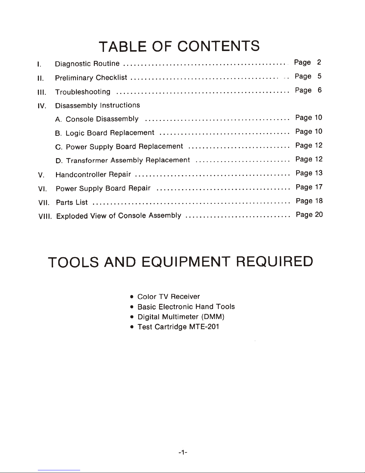
I.
Diagnostic Routine
TABLE OF
..............................................
CONTENTS
. Page 2
II. Preliminary Checklist
III. Troubleshooti ng
IV. Disassembly Instructions
A. Console Disassembly
B.
Logic Board Replacement
C.
Power Supply Board Replacement
D.
Transformer Assembly Replacement
V.
Handcontroller Repai r
VI. Power Supply Board Repair
VII. Parts List
VIII. Exploded View
........................................................
of
.........................................
.................................................
..................................
Console Assem bly
.....................................
.............................
.........
......................................
..............................
.
.................
.
.........
. Page 5
Page 6
Page 10
Page 10
Page 12
Page
Page 13
Page 17
Page 18
Page
12
20
TOOLS AND
•
• Basic Electronic Hand Tools
• Digital
• Test Cartridge MTE-201
EQUIPMENT
Color
TV Receiver
Multimeter
(DMM)
REQUIRED
-1-

DIAGNOSTIC
ROUTINE
SECTION
Follow
malfunction.
CHECKLIST
TROUBLESHOOTING
TURN
1.
Connect
plug
in
to
TV and
I.
this
power
determine
procedure
Then
refer
(Section
ALL
the
AUTOMATIC
Master
cord, set
until
to
the
II, page 5 )
(Section
Component
the
Antenna
that
the
rectly on broadcast stations.
problem,
refer
to
the
CHECKLIST.
2.
Set
the
Antenna
the
Channel
Select
deSignated channel
Switch
switch
for
the
Box
of
Master
you
find
PRELIMINARY
and
III,
page
6 )
COLOR CIRCUITS
to
TV,
Switch
set
works
If
there is any
PRELIMINARY
to
GAME. Set
the TV
Component.
to
Box
cor-
the
a
and
locate
instructions
assembling
this
DIAGNOSTIC
TO
(b.) Press
Hand
the
Hand
letters
Controllers
pair
of
Fs
(c.) Press each
Controllers
Land R change
(d.) Depress
Hand
in
rotated,
the
Controller
the
black
the
arrow
pOints in 16
the
problem
to
correct
the
Master
ROUTINE
MANUAL
the
top
one
change
lower
one
at a
the
and a
circle. As
arrow
wi
II
or
condition.
the
fault.
Component,
Follow
Before
go
through
again.
POSITION.
side
buttons
at a time. Make sure
from
yellow
side
button
time
and see
from
yellow
directional
white
rotate.
different
arrow
the
directional
Check
directions.
on
to
white.
on
that
to
white.
disc
on
will appear
disc
to
see
re-
the
that
the
the
each
is
that
CARTRIDGE
3.
I nsert
the
ON/OFF
depress
ponent.
of
checks.
4.
At
the
the
Reset
The
unit
the
completion
sequence, the
appear
as
shown
MTE-201
Switch
Button
will
Hand
Controller
in
Figure
Test
to
the
on
proceed
of
1.
Cartridge.
ON
position
the
Master
through
the
above test
test
display
Slide
and
Com-
a series
will
(e.)
Check
similarity
as listed in Figure
Next, depress
neously
sequence
I F
I
on
1
L
either
will
l:r
1
4 5
7
c 0 E
812345678
•
the
the
Hand
proceed
9
TO
2 3
6
FI
8 9
RI
row
of
digit
keys 1 and 9
Controller
to
the
CONTINUE
1 2 3
4 5 6
I
F
7 8 9
I L
c o E
colored
1.
and
sound
boxes
simulta-
the
checks.
FI
RI
for
test
(a.) Press each key
trollers,
one
at a
corresponding
white
NOTE:
when the
The
right
time
test image
appropriate
Hand
on
the
and
verify
turns
key is depressed.
Controller
from
left test image and vice versa.
Hand
that
Coneach
yellow
will affect
to
the
-2-
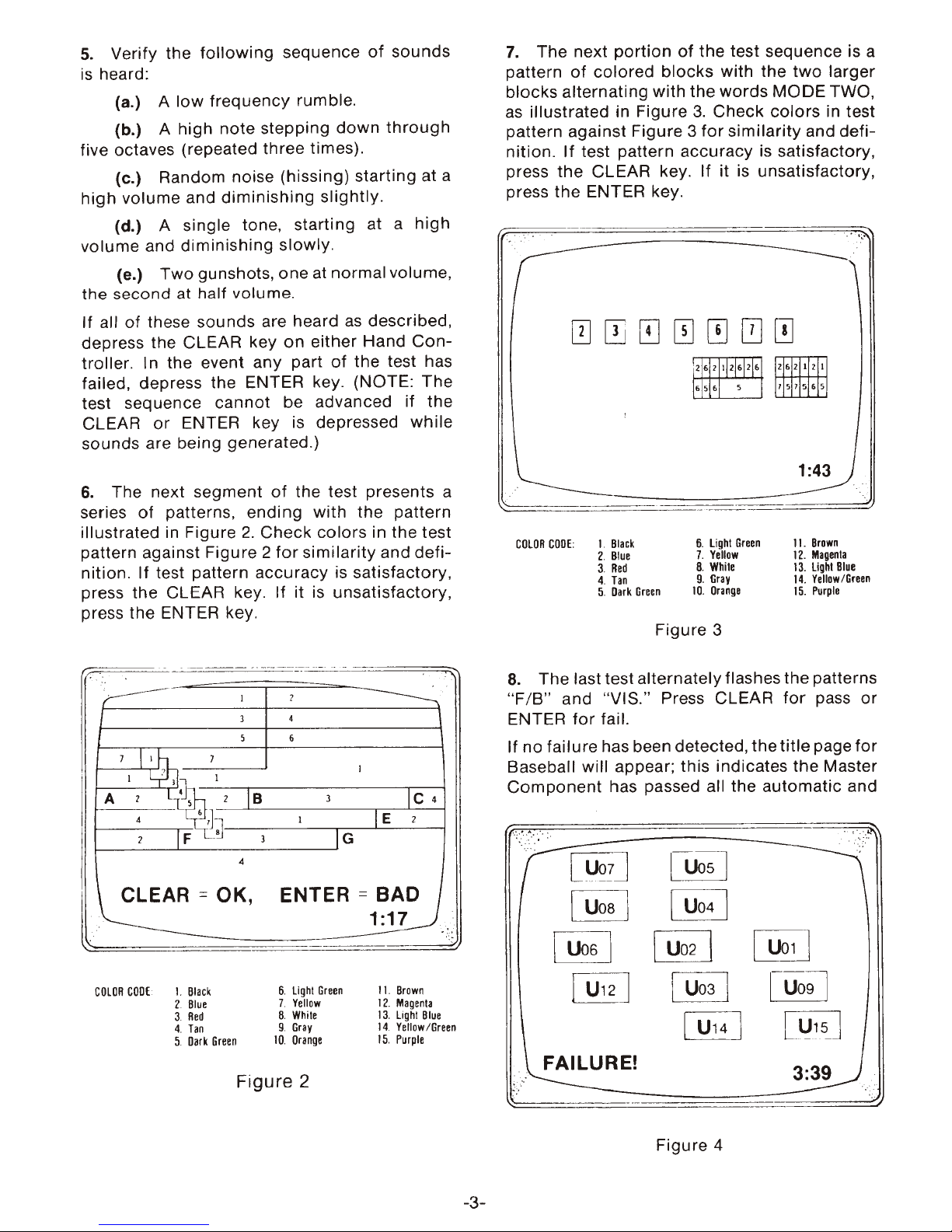
COLOR
CODE:
Figure
1
I.
2.
3.
4.
5.
Blick
Blue
Red
Tin
Dirk
Hand
Green
6.
light
Gr
Yellow
White
GrlY
Orlngl
•• n
7.
8.
9.
10.
Controller
II.
BrDwn
12.
Mlgenll
13.
LIght
Blul
14.
YIIIDw/Bnen
15.
Purple
Test Pattern
5.
Verify the
is
heard:
(a.) A
(b.) A high
following
low
frequency
note
sequence
rumble
stepping
.
down
five octaves (repeated three times).
(c.) Random noise (hissing)
high
volume and
diminishing
starting
slightly.
of
sounds
through
at a
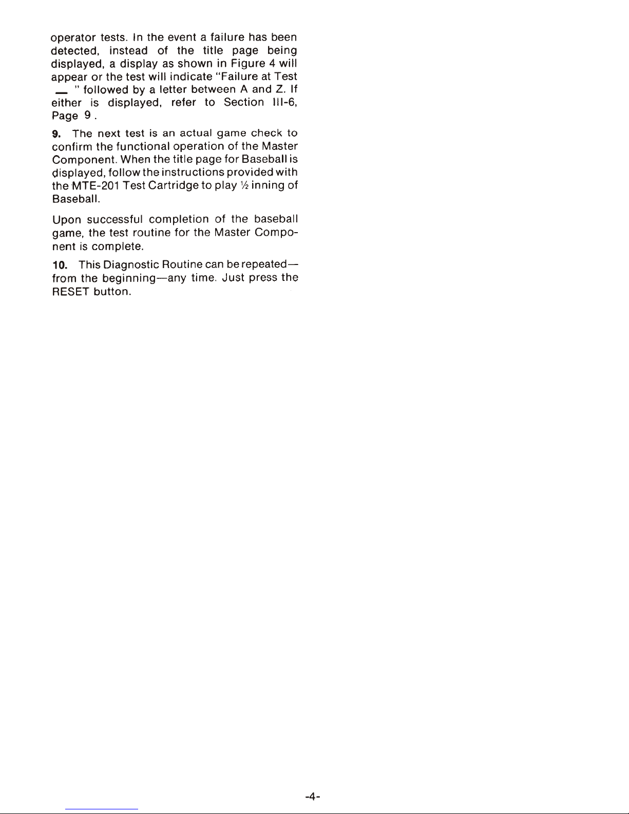
7.
The next
pattern
of
colored
portion
blocks
of
blocks alternating with
as
illustrated in Figure
pattern against Figure 3
nit
ion.
If
press
test pattern
the
CLEAR key. If it is unsatisfactory,
accuracy
press the ENTER key.
the test sequence is a
the
3.
for
Check
with the
words
similarity
two
MODE
colors
and
larger
TWO,
in test
defi-
is satisfactory,
(d.) A single tone, starting at a
volume
the
If all
depress the CLEAR key
and
diminishing
(e.)
Two
gunshots, one at normal volume,
second
of
at
half
volume.
these sounds are heard
slowly
on
either Hand
.
as
described,
high
Controller. I n the event any part of the test has
failed, depress the ENTER key. (NOTE: The
test sequence
CLEAR
or
cannot
be advanced if the
ENTER key is depressed
while
sounds are being generated .)
6.
The next segment
series of patterns,
illustrated in Figure 2.
pattern against Figure 2
nition
. If test pattern
press the CLEAR key. If it is
of
the test presents a
ending
Check
for
accuracy
with the pattern
colors
similarity
in the test
and defi-
is satisfactory,
unsatisfactory
press the ENTER key.
..
r .
. - -
>---
7~
I ' 1
A '
.
~OK,
.
L'~'
4 6
IF
2
--
7
rJ~
8
.- ..
--
.-
I ?
J
5 6
1B
3
4
. -
4
I
ENTER
...
3
-
IG
_ .
~
I
IE
=
BAD
1:17
Ie
2
4
'.
'
.~
1:43
~
.
__
_ _ .-_
-=-=-=
= =
==::::J
6.
Light
10.
7.
B.
9.
Yellow
While
Gray
Orange
Green
title
automatic
~
11.
12.
13
14
15.
for
.
.
Brown
Magenla
Lighl
Blue
Yellow/Green
Purple
pass
or
page
for
and
I.
COLOR
CODE
,
Black
:
2. Bl
ue
3.
Red
4.
Tan
5.
Dark
Green
Figure 3
8.
The last test alternately flashes the patterns
"FIB"
ENTER
If
and "VIS." Press CLEAR
for
fail.
no
failure has been detected , the
Baseball will appear; this indicates the Master
Component
".-
~
has passed all the
[
l.J<J!
J
~
~
LUosl
~
6.
Light
COLOR
CODE
I.
2.
3.
4.
5.
Black
Blue
Red
Tan
Dark
Green
7.
Yettow
8.
White
9.
Gray
10. Orange
Green
Figure 2
II.
Brown
12.
Magenta
13
.
Light
14
.
Yettow/Green
15. Purple
Blue
-3-
~
~
~
Figure 4
1-
Uo
[lJ1S
9]
J
operator
detected. instead
displayed. a
appear
_
tests . In the event a
display
or
the test will
"followed
by a letter between A and
of
the
as
shown
indicate
either is displayed . refer
Page
9.
failure
title
page being
in Figure 4
"Failure
to
Section
has been
will
at Test
Z.
If
111-6.
9. The
confirm
Component. When the
displayed.
the
next
test is an actual game
the
functional
follow
MTE-201 Test
operation
title
the
instructions
Cartridge
page
to
play
of
for
provided
Baseball.
Upon
game. the test
nent
10. This Diagnostic Routine can be
from the
RESET
successful
is
complete.
beginning-any
button
completion
routine
.
for
the Master
time. Just
of
the
check
to
the Master
Baseball is
with
112
inning
of
baseball
Compo-
repeated-
press
the
-4-

PRELIMINARY CHECKLIST
SECTION II:
Before you refer
Section
Turn
the
which
ON/OFF
DIAGNOSTIC
BUZZING
follows,
Switch
to
the
TROUBLESHOOTING
look
to
ROUTINE
SCREEN IS
NO
OR
DISTORTED
at
this
list
ON
and press RESET.
and
check
PROBLEM POSSIBLE
BLANK
TV
PROGRAMS
SOUND
of
pos-
With
for
these problems:
sible
persists, you
TROUBLESHOOTING.
the
quick
Test
solutions. Then,
should
Cartridge
be able
still inserted,
SOLUTION
- Press
key pad
-
Check
Switch
TV.
- Make sure
TV.
- Make sure that coax cable is attached.
-
Adjust
- If there is broadcast interference
strong
from
reconnected
any
key on
to
recover picture.
connection
Box
to
Antenna
TV
fine
signal,
Antenna
for
either
of
antenna
tuning
disconnect
Switch
broadcast viewing.)
Hand
cable
Switch
controls.
Box. (This
if
any problem
to
find
go
Controller
from
Antenna
connector
Box is set at
antenna coax
from
must
on
be
it
through
a
in
NO
GAME
OR SCREEN
SNOWY SCREEN (NO
TEST
IMAGE
AS IF FROM WEAK
TEST
WOBBLY, OR
SOUND
WHITE-GRAY
IS
NOT
IMAGE
EFFECTS -
SCREEN
ONE
COLOR
RF
CARRIER) - Make sure:
DISTINCT
SIGNAL
BLURRED ,
NO
COLOR
Turn
-
Adjust
- Make sure
-
TV
Antenna
Game
Antenna
- Power
- Check all
plug
,
-
Adjust
trast
Check
-
Box,
output
-
Adjust
and color.
up TV
fine
tuning
cartridge
tuner
is set
Switch
coax cable is
Switch
switch
connections, including
.
fine
tuning
controls
connections
TV
antenna
connector.
fine
volume
is ON.
.
tuning,
control.
.
is
properly
on
the
proper
Box is set at GAME.
properly
Box
.
, brightness, and con-
at
Antenna
connector,
brightness, contrast,
inserted.
channel.
plugged
power
Switch
and game
into
If
there
strong
from
reconnected
-5-
is
broadcast interference
signal, di
Antenna
sconnect
Switch
for
broadcast viewing.)
antenna cable
Box
. (This
from
must
a
be
TROUBLESHOOTING
SECTION
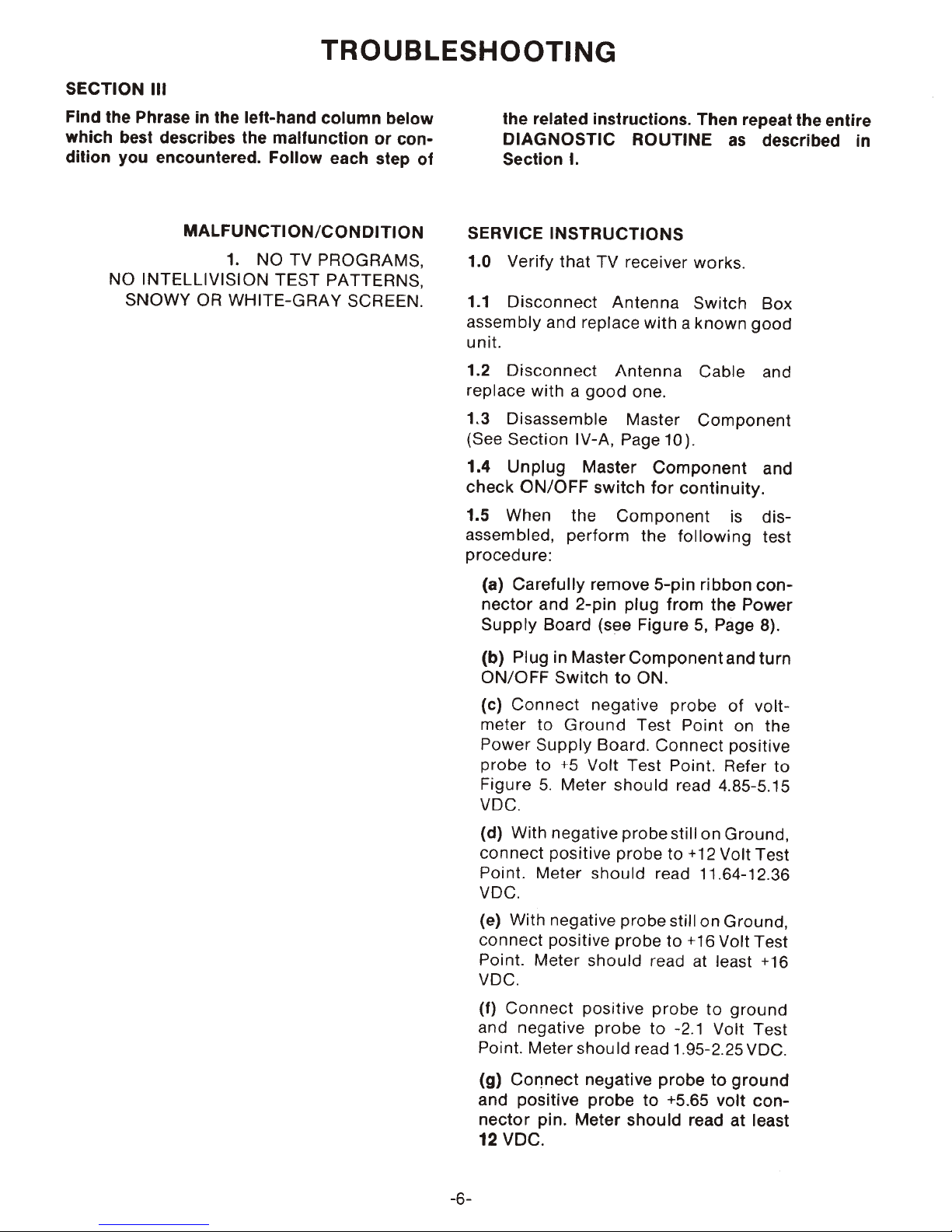
Find
the
which
dition
best describes the
you
NO
SNOWY
III
Phrase
INTELLIVISION
in
the
left-hand
encountered.
MALFUNCTION/CONDITION
1.
OR
WHITE-GRAY
column
malfunction
Follow
NO
TV
PROGRAMS,
TEST
PATTERNS,
or
each
step
SCREEN .
below
con-
of
the related
DIAGNOSTIC
Section
SERVICE
1.0
Verify
1.1
Disconnect
assembly
unit.
1.2
Disconnect
replace
1.3
(See
1.4
check
with a good
Disassemble Master
Section
Unplug
ON/OFF
instructions.
I.
INSTRUCTIONS
that
and replace
IV-A,
Master
1.5 When the
assembled,
procedure:
perform
ROUTINE
TV
receiver works.
Antenna
with a known
Antenna
one.
Page10).
Component
switch
for
Component
the
Then
repeat
as
Switch
Cable and
Component
continuity.
is
following
the
described
Box
good
and
distest
entire
in
(a)
Carefully
nector
Supply
(b)
ON/OFF
(e)
meter
Power
probe
Figure
VDC.
(d)
connect
Point.
VDC.
(e) With negative
connect
Point.
VDC.
(f)
and negative
Point. Meter
and
Plug in
Connect
to
Supply
to
5.
With negative
Meter
Meter
Connect
remove
2-pin
Board
Master
Switch
Ground
+5 Volt
Meter
positive
positive
should
positive
should
(see
negative
Board.
should
probe
5-pin
ribbon
plug
from
the
Figure
Component
to
ON.
Test
Test
should
probe
probe
probe
probe
read 1.95-2.25 VDC.
5, Page 8).
and
probe
Connect
Point. Refer
read 4.85-5.15
still
to
read 11.64-12.36
still on Ground,
to
read at least +16
probe
to -2.1 Volt Test
of
Point
positive
on
Ground,
+12 Volt Test
+16 Volt Test
to
ground
con-
Power
turn
volt-
on
the
to
(g)
and
nector
12 VDC.
-6-
Connect
positive
pin.
neyative
probe
Meter
probe
to
+5.65
should
to
read
ground
volt
at
conleast
 Loading...