

Page 1
User’s Guide:
Fluidized Filling System
45490 Ruritan Circle
Sterling, Virginia 20164
703.964.0400
info@matsys.com
www.matsys.com
Page 2

Table of Contents
• Introduction 2
• Fluidized Fill Shoe 2
• Control Cabinet 3
• Fluidization Principle 4
• System Set-up and Installation 5
• Gas Supply 5
• Fluidizer Control 6
• Mounting the Shoe 7
• Connection to Control Cabinet 8
• Initial Set-up 8
• Check-out Procedure 9
• Operation 10
• Fluidizer Care 10
• Calibration Chart A 12
• Appendix A – Quick Reference 13
• Appendix B – Operation 14
• Electrical Wiring Diagram 16
1
Page 3
INTRODUCTION
The MATSYS Fluidized Fill Shoe System (FFS) is a powder delivery system
designed for consistent, fast and uniform filling of small die cavities. It can be used on a
wide variety of particulate materials. The FFS system includes a fluidized fill shoe and a
control cabinet. The fluidized fill shoe design incorporates two main components: a
transport tube and a delivery chute. Fluidization of the transport tube and delivery
chute is controlled separately using gas pressure control and individual adjustable flow
meters.
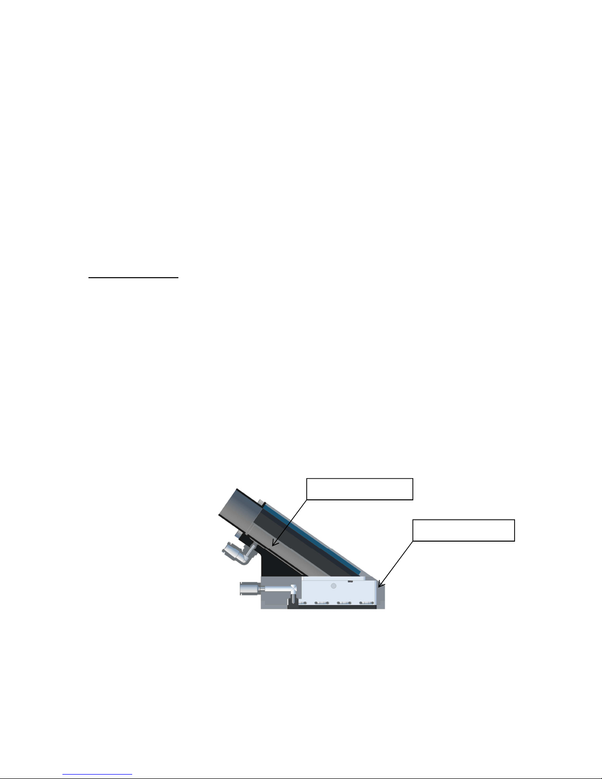
Fluidized Fill Shoe
The fluidized fill shoe design consists of two main components: a transport tube
and a delivery chute. These are independent gas chambers used to fluidize the
particulate material prior to delivery and fill of the die cavities. These chambers are
illustrated in Figure 1. Powder is supplied to the fluidized fill shoe by connecting a 2”
I.D. hose to the connection on the top of the fluidized fill shoe transport tube. The
fluidizing process begins in the transport tube and conveys the particulate material to
the delivery chute. When the particulate material reaches the delivery chute, two multi-
loop fluidizers, a top loop and a bottom loop, located inside the delivery chute keep the
particulate material in a fluidized or loose state until it reaches the die opening. These
two loop fluidizers inside the delivery chute are controlled independently.
Transport Tube
Delivery Chute
Figure 1. Illustration of the fluidized fill shoe components.
The following is a brief description of each of the fluidized fill shoe components:
2
Page 4

1. Transport tube. The transport tube provides the connection between the
particulate material supply hose and the delivery chute. It begins the process
of conditioning the particulate material to a fluidized or loose state and
conveys the particulate material to the delivery chute.
2. Delivery chute. The delivery chute functions as the powder discharge unit
directly above the die cavity. It has two multi-loop fluidizers, a top loop and
a bottom loop, to loosen and fluidize the particulate material before it
reaches the die opening.
Control Cabinet
The control cabinet houses the gas controls for the FFS system. These controls
regulate powder fluidization in relation to the movement of the fluidized fill shoe on the
press. An optional combination in-line moisture separator, filtration system and gas
dryer to remove moisture and solid contaminants from the gas supply. Three
independent pressure regulators (0-5 psi) and pneumatic solenoids are used to regulate
the flow of gas to each of the three FFS independent fluidizers, namely, the transport
and the two fluidizer loops inside the delivery chute. The solenoids are timed to control
fluidization of the powder when the fill shoe is over the die cavity. Three flow meters
(up to 30 SCFH) are used to independently monitor the gas flow to each of the three
fluidizers independently.
3
Page 5

FFS BASIC PRINCIPLE
Powder flows like a fluid when supported by a column of gas. The result is a
reduction in the effects of head pressure, clumping and surge, both of which are
common in gravity fed systems. The fluidized fill shoe creates a low pressure gas
bearing below the powder inside the shoe to reduce the friction along the powder path
to the fill point.
The FFS was developed to improve powder flow consistency, powder flow
uniformity, increase powder flow rates, and improve the speed of filling die cavities. By
flowing gas through a bed of solid particles from the bottom to the top, the bed is
loosened and fluidized, and particles are easier to move. The FFS uses a dry gas, such as
air, nitrogen, or argon to “coat” particles and separate them, thereby greatly reducing
inter-particle friction, improving powder flow consistency, and increasing powder flow
rates. The gas provides a transport mechanism reducing inter-particle friction and
thereby reducing the need for bulk lubricants in the powder blend.
4
Page 6

SYSTEM SETUP AND INSTALLATION
1. Gas Supply
The most optimal method of fluidizing is to use an inert gas such as Argon,
alternatively compressed air can be used when properly treated, dried and filtered.
When a compressed air source is used to supply air pressure to the fluidized fill shoe,
the gas control supply pressure should be between 30 and 60 psi. The FFS control
cabinet will provide instrument quality air to the fluidized fill shoe as long as care is
taken to maintain a quality air supply, i.e. air that is free of oil, dirt, and moisture. To
prevent moisture build up in the gas lines it is common practice to install an
appropriately sized after-cooler and moisture separator system on a shop air
compressor. As an extra precaution, it is recommended that a secondary liquid
separator and trap be installed ahead of the FFS control cabinet as shown in Figure 2.
During normal use, and especially during initial setup of a new system, the
quality of the air supply should be closely monitored for any oil, moisture, or solid
contamination.
For systems equipped with a desiccant dryer
The functionality of a desiccant gas dryer can be readily checked by observing
the dew-point indicator particles which are mixed into the desiccant located inside the
dryer:
♦ When the indicator particles color is blue, the dryer function is normal and it
is O.K. to operate the system.
♦ When the indicator particles color is pink, the outlet air is humid. It is time to
replace the desiccant before you operate the system.
For systems equipped with a membrane dryer (optional)
The desiccant dryer can be upgraded to a very low maintenance membrane
dryer. With a membrane dryer you can readily check outlet moisture condition by
observing the dew-point indicator which is located on the top of the membrane dryer:
♦ When the dew-point indicator is blue, the operation is normal.
♦ When the dew-point indicator is pink, the outlet air is humid.
Note: It takes approximately 1 hour to change the color of the dew-point
indicator from the start-up of supply air.
5
Page 7

Figure 2. It is recommended that the customer air supply line be plumbed as
shown with a vertical inlet pipe to separator, trap, and drain valve.
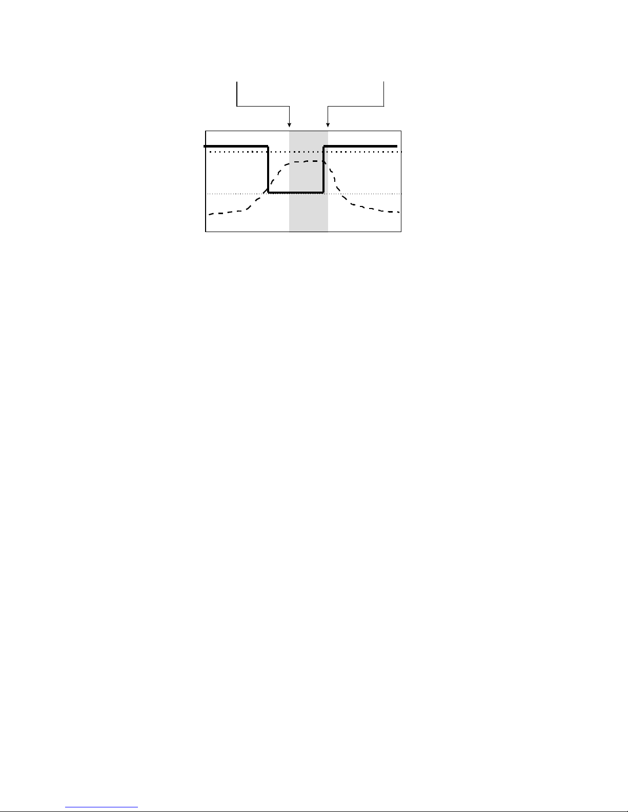
2. Fluidizer Control
Fluidization ‘ON’ / ‘OFF’ control is used to optimize the filling process. To use
fluidization ‘ON’ / ‘OFF’ control you will need to connect a dry contact closure control
from your press to the remote control signal connection terminals fluidizer control box.
When the 24-volt DC control signal is present gas is supplied to the fluidizers. The
optimum timing used in most applications is called “continuous off.” This timing
configuration refers to the fluidization being off for the entire stroke except when the fill
shoe is extended toward the die cavity, as shown in Figure 3. In other words, the gas is
turned on just before the fill shoe is pushed forward and remains on during the dwell
time over the die cavity. The gas is then turned off just before the shoe is pulled back.
6
Page 8
fill shoe centered over die cavity
“dwell time”
OFF
ON
relative
degree
0
90
180
270
solenoid
fill shoe
movement rate
360
Figure 3. Typical fluidized fill shoe solenoid timing chart, “continuous off.”
3. Mounting the Shoe on the Press
Mounting the fluidized fill shoe on the press is a simple procedure. However, it
is important to strictly observe the following mounting requirements:
1. Center the delivery chute over the die cavity. Because the fluidized fill shoe
delivery chute is typically smaller than a conventional gravity fill shoe, the
accurate centering of the delivery chute over the die cavity is very important.
The alignment tolerance of side-to-side and front-to-back positioning of the
chute should be kept to within approximately +/- 1/16”. Alignment can be
performed by using a marking pen and square to draw the die centerline
crosshairs directly on the press table. These cross hairs can then be aligned
with scribe marks located on the front and sides of the delivery chute.
2. Check the action of the seal between the delivery chute and the die. Before
applying a hold down force to the fluidized fill shoe, check for clean wipe or
scrape of the powder during retraction.
3. Apply pressure to hold down the fluidized fill shoe. After centering the
delivery chute over the die cavity and inspecting the seal, apply down arm
pressure to the fluidized fill shoe. The down arm force should be minimized.
Use just enough downward force to maintain a good seal around the die
cavity during the dwell portion of the stroke. It is recommended at this time
to manually cycle the fill shoe in and out over the die cavity and observe the
action of the fill shoe. Note that hold down force is adjusted by rotating the
four ½” threaded spring plungers located on each corner of the filler.
While manually cycling the fill shoe watch for the following:
7
Page 9

The fluidized fill shoe should follow a reproducible path for
each stroke. This can be observed by sprinkling some excess
powder around the die opening and observing the powder
wipe trail during each stroke of the shoe. If there is excessive
lateral or axial play in the fluidized fill shoe retraction
mechanism, the shoe will wander as it moves in and out. This
will sometimes show up as a series of powder streaks left by
the seal on the delivery chute. The streaks typically show up
on each side of the delivery chute seal rather than a single
continuous line of excess powder. If there is too much play in
the fluidized fill shoe retraction mechanism use washers or
shims to remove this play before beginning a production run.
A loose fluidized fill shoe retraction mechanism can cause
large variations in part weight consistency.
4. Connecting the Fluidized Fill Shoe to the Control Panel
Two (or three, depending on the model) tubes are provided to connect the
fluidized fill shoe to the control cabinet. Each tube is 10 ft (3 m) long. The control
cabinet should be mounted vertically. The hoses connect to the fittings on the side of
the control cabinet to the fittings on the fluidized fill shoe.
5. Initial Setup
The following steps should be followed for initial setup of the FFS:
1. The control box must be mounted vertically so that the flow meters, gas
dryer and filter work properly.
2. Connect clean, DRY, oil free gas (30-60 psi) to the inlet on the box
3. Bolt or clamp the tubing strain relief connector block to a rigid point on the
press to avoid undue mechanical forces acting on the fluidized fill shoe from
the1/4” tubing during use. Connect the white or blue tubing to the delivery
chute and the green tubing to the transport tube.
8
Page 10

6. Checkout Procedure
If you are using the system for the first time you must complete the initial setup
outlined above before performing the following checkout procedure. You should also
perform this checkout procedure if the system has been out-of-service for an extended
period of time or if you suspect a performance problem.
This checkout procedure will verify proper operation of the gas control system as
well as the condition of the transport tube and delivery chute fluidizers.
1. With gas supply off, read pressure gauges and adjust reading to “0” as
necessary.
2. With gas supply on and no output tubing connected to the control box, set all
of the regulators to 1 psi and fully open all of the flow control valves.
3. Test correct operation of the solenoid valves by turning on the manual pilot
switch on the primary relay. This should turn on all of the solenoids and as a
result an increase in gas flow should be seen in the flowmeters. If included,
the lights in the solenoid electrical connectors as well as the blue indicator
light should also illuminate. With correct operation of the control box
confirmed, turn off the manual pilot switch on the primary relay.
4. Make sure that all tubing is connected properly (refer to Figure 2).
5. With no material in the fill shoe, adjust the gas pressure regulator to the
values shown in the “Fluidizer Gas Calibration Chart” supplied with your
system and read the gas flow values on each of the flow meters. Compare
readings with the values in the calibration chart.
6. Verify that you get approximately the same flow values as those printed in
the “Fluidizer Gas Calibration Chart”.
If you experience problems obtaining similar values to those given in the chart,
contact MATSYS before proceeding. Otherwise you are ready to operate the fluidized
fill shoe.
9
Page 11

7. Operation
For first time use you should adjust the gas pressure regulator and flow meters
as follows:
1. Connect powder hose from hopper to transport tube.
2. With particulate material in the fluidized fill shoe, set the gas pressure
regulator to a minimum of 0.25 psi.
3. Run press and check the fill quality.
4. Increase the gas pressure in 0.25 psi increments as needed to achieve the
flow rate you want. The lowest possible gas pressure which yield full fill is
normally the optimum operational set point.
5. Once you have set the pressure, no further adjustment is necessary. It is
recommended that you periodically perform the initial checkout to verify
that the system is functioning properly. Under continuous production
operation the initial checkout procedure should be performed on a weekly
basis.
Factors that can affect the flow set point are:
• Powder type – density, and general flow characteristics.
• Flow rate - production speed and fill volume.
• Punch, die geometry and number of die cavities.
8. Transport Tube and Delivery Chute Fluidizer Care
Care should be taken not to contaminate the fluidizer porous plates with foreign
matter that might cause flow restriction. Avoid contacting the porous plates with the
following material types: ultra fine particulate (particles smaller than the porous
fluidizer plate 0.5 micron rating), adhesives, gelatins, pastes or hardening resins, and
non-evaporative liquids.
If contamination of the fluidizer porous plates is suspected, you may be able to
clean the plate with isopropyl alcohol to revive it. To clean the porous plate, adjust the
gas pressure to approximately 3 psi with the flow meters fully open (counterclockwise).
This will allow the gas to flow through the porous plate while you swab the plate with an
alcohol soaked Q-tip.
10
Page 12

If cleaning the fluidizer porous plates in this manner does not remove the
contamination, the plate will need to be cleaned with an ultrasound cleaner. In this
case, you need to remove the fluidizer loop, and follow the basic process steps:
1. Presoak the fill shoe in 70 % isopropyl alcohol* for approximately 5 minutes.
2. With no gas flow, ultrasound for 5 minutes.
3. With 2-3 psi gas pressure, ultrasound for another 5 minutes.
4. (This step is required only when substituting # 222 cleaning solution or
similar for isopropyl alcohol, refer to note below). Post soak in 70 %
isopropyl alcohol* for approximately 5 minutes. This post soak should be at
room temperature for 2 minutes with no gas flow, and then with gas flow
pressure set at 2-3 psi.
5. Air dry at room temperature with 2-3 psi gas pressure for 1 hour.
6. Test the flow again referring to the flow calibration sheet and return the fill
shoe to service if flows are within 1 SCFH of the original values on the flow
calibration sheet.
* Important Note:
Isopropyl alcohol is considered a flammable liquid
To be safe avoid heat, sparks, and open flame. The typical rated
flashpoint for isopropyl alcohol is 72o F. Ultrasonic cleaners generate heat and
therefore must be appropriately cooled or purged when containing alcohol. A
recommended substitute for alcohol is L&R Manufacturing # 222 ultrasonic
cleaning solution. If # 222 or similar cleaner is used you must use Step
# 4
above after ultrasound to flush residual cleaner from the filler.
If cleaning the fluidizer porous plate in the described manner does not remove
the contamination, the plate may need to be repaired or replaced. In this case it is
recommended that the fill shoe be returned to MATSYS for service.
11
Page 13

Fluidizer Gas Calibration Chart A
Gas
Pressure
(psi)
Transport
Tube
(SCFH)
Delivery
Loop
(SCFH)
0.25
0.5
0.75
1.0
Gas Type: Air
Length of Tubing: 6 feet
Delivery Chute Type: PTFE Loop
Transport Rating: 5 micron
12
Page 14

APPENDIX A
QUICK REFERENCE
FOR
PROPER OPERATION OF THE FLUIDIZED FILL SHOE
Before connecting the hose from the hopper to the fill shoe (with no material in the
fill shoe)
1. Check desiccant:
• Desiccant dryer color should be blue. If color is pink replace desiccant.
2. Check tubing:
• White/Blue tubing is connected to the Delivery Chute.
• Green tubing is connected to the Transport Tube.
3. Check pressure gage:
• Gage should read “0” with supply air disconnected. If not “0” readjust prior to
connecting the air supply.
4. Check for leaks or clogs in Transport Tube and Delivery Chute:
• Set regulator to 1 psi and read flow rates.
• Flow rates should be within +/- 2 SCFH of those listed on the calibration chart.
Flow outside of the range of the flowmeter indicates a leak. Very low flow may
indicate a clog.
After connecting the hose from the hopper to the fill shoe (with material in the fill
shoe)
1. Set pressure:
• Set pressure to 1 psi (or known optimum pressure for the part and material).
2. Start press.
During Press Downtime, Maintenance, Service, Lunch Break, etc. (with material in the
Fill Shoe)
Always turn off the airflow supply to the Transport Tube and Delivery Chute.
13
Page 15

APPENDIX B
FFS OPERATION
Once the fluidized fill shoe is mounted on the press and proper operation is
verified, it is important to periodically check the fluidized fill shoe performance during
extended production runs. The following chart summarizes the fluidized fill shoe
operational readiness checks along with the recommended time periods between
checks.
CHECK
GAS SUPPLY
GAS SUPPLY
FLUIDIZER CONTROL
FLUIDIZER GAS
PRESSURE
DETAIL
MOISTURE - If a gas dryer is used,
inspect desiccant site gauge for
moisture contamination:
blue = GOOD
pink = REPLACE
CONTAMINATION - Sub-micron
porous plate should be monitored
for excess pressure drop.
TIMING - Check that the
“ON”/”OFF” timing of the fluidizer
solenoid valves is correctly set by
observing solenoid indicator lights
and gas flow meters in
relationship to the fill shoe
position over the die.
SET POINT – The fluidizer gas
pressure settings should be
checked to verify that they are at
the correct values (about 1.25 psi
average).
WHEN
Before / after each
run
Before / after each
run
Before each run
Before each run
14
Page 16

FLUIDIZER GAS FLOW
WEAR PLATE
SHOE ALIGNMENT
SHOE TRACKING
SET POINT – The fluidizer gas flow
settings should be checked to
verify that they are at the correct
values. See factory calibration
values below.
The wear plate around the chute
opening should lay flat along the
press table with no gaps.
Be sure that the chute opening is
centered over the die cavity at the
peak of the press fill stroke.
Scribe lines on the front and both
sides of the shoe can be used to
locate left to right center and
front to back center.
Be sure the shoe is tracking
perpendicular to the front edge of
the press table as it moves in and
out.
Before each run
Before each run
Before each run
Before each run
15
Page 17

16
 Loading...