

Matsushita MPE-33R User Manual
INSTALLATION AND
OPERATING INSTRUCTIONS
®
MERIT PLUS SERIES
LENNOX HEARTH PRODUCTS
33" Electric Fireplace
P/N 850,032M REV. A 02/2006
MODEL:
This manual will enable you to obtain a safe, effi cient and dependable
installation and operation of your electric fi replace. Please read and
understand these instructions before beginning your installation.
Do not alter or modify this fi replace or its components under any circumstances. Any modifi cation or alteration of the fi replace system, including
but not limited to the fi replace and accessories, may void the warranty,
listings and approvals of this system and could result in an unsafe and
potentially dangerous installation.
IMPORTANT! IF OPTIONAL GLASS DOORS ARE PURCHASED, TO
ASSURE PROPER ALIGNMENT, INSTALL THIS FIREPLACE IN A
SQUARE AND PLUMB CONDITION, USING SHIMS AS NECESSARY
AT SIDES. THIS APPLIANCE IS MOUNTED ON RUBBER FEET TO
ENSURE ADEQUATE AIR CIRCULATION BENEATH FIREPLACE.
DO NOT BLOCK AIRFLOW AT THE BOTTOM AIR INTAKES.
MPE-33R
SAVE THESE INSTRUCTIONS
FOR FUTURE REFERENCE
INSTALLER: DO NOT DISCARD THIS MANUAL
PLEASE LEAVE FOR THE HOMEOWNER
DO NOT STORE OR USE GASOLINE OR OTHER FLAMMABLE
VAPORS AND LIQUIDS IN THE VICINITY OF THIS OR ANY OTHER
APPLIANCE.
A French manual is available upon request. Order P/N 850,032CF
Ce manuel d’installation est disponible en francais, simplement en
faire la demande. Numéro de la pièce 850,032CF.
C
NOTE: DIAGRAMS & ILLUSTRATIONS NOT TO SCALE.
FOR YOUR SAFETY
®
Report # C1482763
US
1
CONGRATULATIONS!
In selecting this DAVE LENNOX Merit Plus electric fi replace, you have chosen the fi nest
and most dependable fi replace found anywhere. A beautiful and prestigious addition to
the fi nest homes. Welcome to a Family of hundreds of thousands of satisfi ed LENNOX
Fireplace Owners.
Please read and carefully follow all of the instructions found in this manual. Please
pay special attention to the safety instructions provided in this manual. The instructions included here will assure that you have many years of dependable and enjoyable
service from your LENNOX product.
TABLE OF CONTENTS
Packaging List ...................................Page
2
Introduction ......................................Page
2
General Information ..........................Page
3
Locating Fireplace .............................Page
3
Tools/Supplies Required .................. Page 3
Framing Specifi cations ..................... Page 4
Fireplace Specifi cations .................... Page 4
Clearances ....................................... Page 5
Pre-installation ................................. Page 5
Installation Steps ............................. Page 5
Electrical Connections ...................... Page 5
Final Finishing .................................. Page 6
Break-In Period ................................ Page 6
Control Panel Operation ................... Page 6
Remote Control Operation ............... Page 7
Maintenance ..................................... Page 8
PACKAGING LIST
This assembled Electric Room Heater is
packaged with:
• One accessory package located in the
fi rebox, containing;
1. One Installation and Operation Manual.
2. One Warranty Certifi cate.
3. One Remote Control.
• Two spare Light Bulbs are located in a
recess on the back of the log assembly.
INTRODUCTION
This Electric Fireplace is designed for
residential applications to be framed in
as a fi replace.
This appliance has been tested in accordance with UL 2021 and CSA C22.2 No.
46-M198 standards for fi xed and location
dedicated electric room heaters.
Installation must conform to local codes.
In the absence of local codes, electrical
wiring and grounding must comply with
the National Electrical Code ANSI/ NFPA
70 - latest edition. In Canada, the current CSA C22-1 Canadian Electrical Code
- latest edition.
WARNING
If the information in this manual
is not followed exactly, an electrical shock or fi re may result
causing property damage, personal injury or loss of life.
IMPORTANT
Please read and understand
these instructions before beginning your installation.
IMPORTANT
Before starting your fi replace
installation, read this installation and operation manual
very carefully to ensure you
understand it completely and in
entirety. Failure to follow these
instructions may result in a possible electric shock, fi re hazard
and/or injury or property damage
and will void the warranty.
CAUTION
This appliance is mounted on
rubber feet. The purpose of these
feet is to ensure adequate air
circulation beneath the fi replace.
Do not remove these feet. Do not
install the fi replace directly onto
a carpet, rug, furniture or similar
surfaces, which could hinder or
block the airfl ow.
CAUTION
Extreme caution is necessary
when any heater is used by or
near children or invalids and
whenever the heater is left operating and unattended.
TO PREVENT A POSSIBLE FIRE, DO NOT
BLOCK AIR INTAKES OR EXHAUSTS IN
ANY WAY. DO NOT USE NEAR SOFT
SURFACES, LIKE A PILLOW, WHERE
OPENINGS MAY BECOME BLOCKED.
THIS APPLIANCE MAY BECOME HOT
WHEN IN USE. TO AVOID BURNS, DO NOT
LET BARE SKIN TOUCH HOT SURFACES.
KEEP COMBUSTIBLE MATERIALS, SUCH
AS FURNITURE, PILLOWS, BEDDING,
PAPERS, CLOTHES AND CURTAINS AT
LEAST 3 FEET (1 METER) FROM THE
FRONT OF THIS APPLIANCE.
DO NOT OPERATE ANY HEATER WITH
DAMAGED WIRING OR CONNECTORS,
OR AFTER THE APPLIANCE MALFUNCTIONS, OR IF IT HAS BEEN DROPPED OR
DAMAGED IN ANY WAY.
ANY REPAIRS TO THIS FIREPLACE
SHOULD BE PERFORMED BY A QUALIFIED
SERVICE TECHNICIAN.
UNDER NO CIRCUMSTANCES SHOULD
THIS FIREPLACE BE MODIFIED. PARTS
HAVING TO BE REMOVED FOR SERVICING
MUST BE REPLACED PRIOR TO OPERATING THE FIREPLACE AGAIN.
2
NOTE: DIAGRAMS & ILLUSTRATIONS NOT TO SCALE.
DO NOT USE THIS APPLIANCE OUTDOORS. DO NOT EXPOSE FIREPLACE TO
THE ELEMENTS (SUCH AS RAIN, ETC.).
THIS APPLIANCE IS NOT INTENDED FOR
USE IN BATHROOMS, LAUNDRY AREAS
OR SIMILAR INDOOR LOCATIONS. NEVER
LOCATE THIS APPLIANCE WHERE IT
COULD FALL INTO A BATHTUB OR OTHER
WATER CONTAINER.
DO NOT RUN ELECTRICAL WIRING OR
POWER CORD (OPTIONAL) UNDER CARPETING. OR COVER WITH THROW RUGS,
RUNNERS OR SIMILAR MATERIALS.
(FOR 120 V W/OPTIONAL POWER CORD)
AVOID THE USE OF AN EXTENSION CORD
BECAUSE THE EXTENSION CORD MAY
OVERHEAT AND CAUSE A RISK OF FIRE.
HOWEVER, IF YOU HAVE TO USE AN
EXTENSION CORD, THE CORD SHALL BE
NO. 14 AWG MINIMUM SIZE AND RATED
NOT LESS THAN 1800 WATTS, 15 AMPS.
THE EXTENSION CORD MUST BE A THREE
WIRE CORD WITH GROUNDING TYPE
PLUG AND CORD CONNECTION.
THIS APPLIANCE HAS HOT AND ARCING
OR SPARKING PARTS INSIDE. DO NOT
USE IT IN AREAS WHERE GASOLINE,
PAINT OR FLAMMABLE LIQUIDS ARE
USED OR STORED.
THIS FIREPLACE SHOULD NOT BE USED
AS A DRYING RACK FOR CLOTHING,
NOR SHOULD CHRISTMAS STOCKINGS
OR OTHER DECORATIONS BE HUNG
NEAR IT.
USE THIS APPLIANCE ONLY AS DESCRIBED
IN THIS MANUAL. ANY OTHER USE IS NOT
RECOMMENDED BY THE MANUFACTURER
AND MAY CAUSE A FIRE, ELECTRIC SHOCK
OR INJURY TO PERSONS.
IF APPLIANCE IS TO BE DISCONNECTED,
TURN OFF CONTROLS FIRST.
DO NOT INSERT OR ALLOW FOREIGN
OBJECTS TO ENTER ANY VENTILATION
OR EXHAUST OPENING, AS THIS MAY
CAUSE AN ELECTRIC SHOCK, FIRE, OR
DAMAGE TO THE APPLIANCE.
SAVE THESE INSTRUCTIONS.
GENERAL INFORMATION
Power Supply Wire Specifi cations
120 Volt, 60 Hz, 1600 Watts:
(ref. Page 10)
Use two conductor, non-metallic sheath cable
with ground wire for the incoming power
supply. The wire used must conform to local
and national electrical codes for the specifi ed
power consumption rating. See Table 1.
240 Volt, 60 Hz, 3000 Watt:
(ref. Page 11)
Use three conductor, non-metallic sheath
cable with ground wire for the incoming power
supply. The wire used must conform to local
and national electrical codes for the specifi ed
power consumption rating. See Table 1.
Wall Switch or Wall Thermostat Kits
(optional kits, see Page 17)
Low voltage wire is provided for the wall switch
connection. The wires gage requirements are
shown on Table 1.
WARNING
Do not install or operate this fi replace through a switch wired in the
120 V AC or 240 V AC circuits. The
only approved wiring for a switch
is through the low voltage circuit
(24 V AC) as shown on Page 14.
Power Supply Wire Gage
Voltage Wire Gage Fuse
Rating
120 V 14 GA. 15 AMP
240 V 14 GA. 20 AMP
Wall Switch / Thermostat Wire Gage
Voltage Wire Gage
5 VOLTS 18 GAGE
Table 1
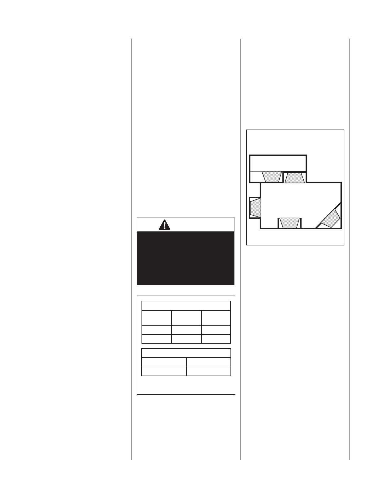
LOCATING YOUR MERIT PLUS ELECTRIC
FIREPLACE
Your new fi replace may be installed into existing
framing or built into a wall (see Figure 1), or
set in a freestanding mantel cabinet available
from your dealer (see Page 17).
When choosing a location for your new fi replace, ensure that the general instructions are
followed. Also, for the best effect, install the
fi replace out of direct sunlight and away from
overhead lighting. See Figure 1.
Top View Showing Approved
Room Locations of Fireplace
fi replace shown in gray.
Figure 1
TOOLS AND BUILDING SUPPLIES
NORMALLY REQUIRED
Tools:
Phillips Screwdriver
7/16" Socket Drive
Hammer
Saw And/or Saber Saw
Level
Measuring Tape
Plumb Line
Electric Drill And Bits
Pliers
Square
Gloves
Building Supplies:
Framing Materials
Wall Finishing Materials
Caulking Materials
(noncombustible)
IMPORTANT NOTE: This fi replace system
is not diffi cult to install. However, in the
interest of safety, it is recommended that
the installer be a qualifi ed or certifi ed
“tradesman” familiar with commonly
accepted fi replace installation and safety
techniques as well as prevailing local
codes.
NOTE: DIAGRAMS & ILLUSTRATIONS NOT TO SCALE.
3
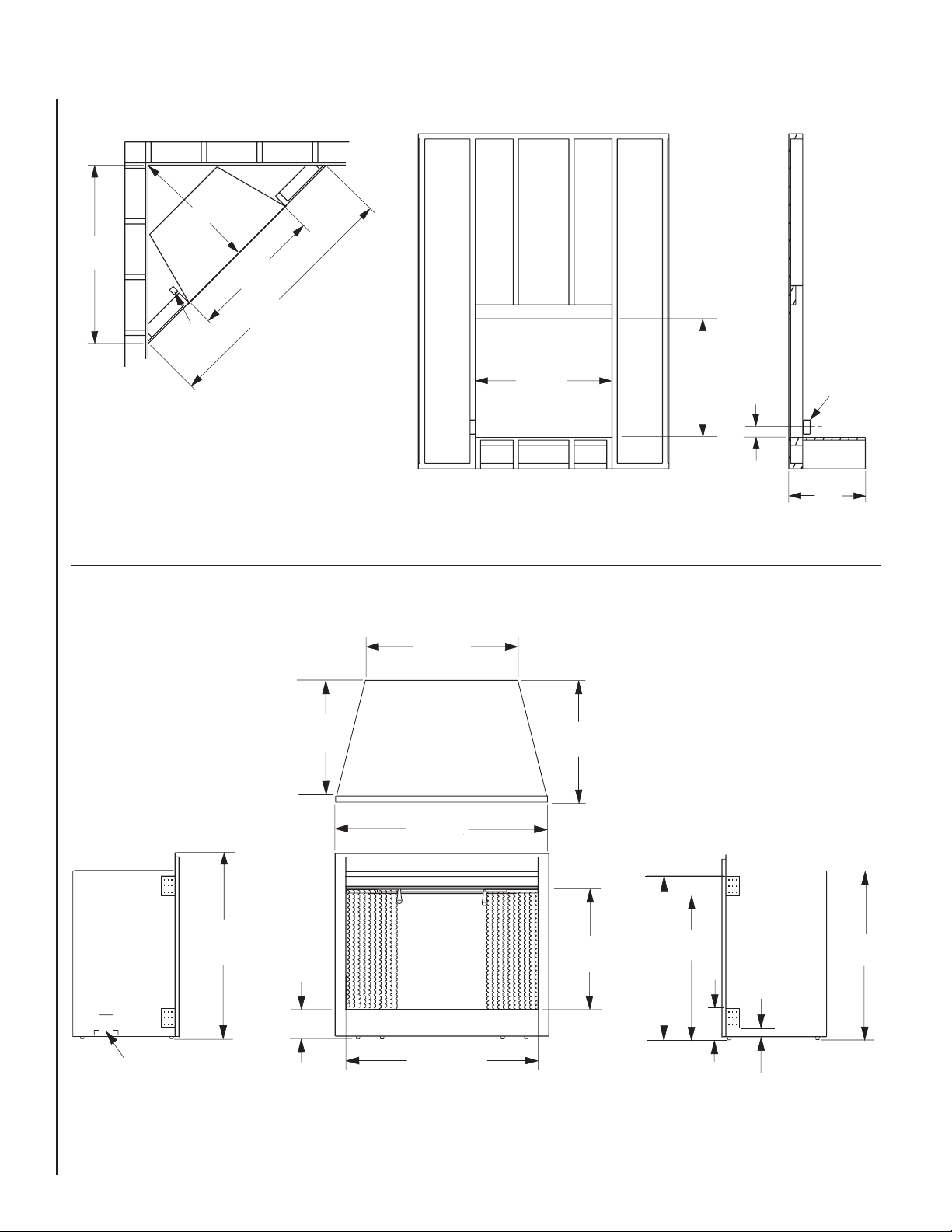
FRAMING SPECIFICATIONS
25 5/8 "
(651 mm)
36 1/4 "
(921 mm)
Electrical
Junction
Box
Corner View
Note: Framing dimensions are calculated for a nailing fl ange depth of 1/2"
Figure 2
35 1/4 "
(895 mm)
51 1/4 "
(1302 mm)
35 1/4 "
(895 mm)
Front View
32 "
(812 mm)
4 "
(102 mm)
Electrical
Junction
Box
(left side)
15 1/8 "
(384 mm)
Side View
FIREPLACE SPECIFICATIONS
32 "
Left Side
Electrical Access
(812 mm)
13 3/4"
(350 mm)
5 1/8 "
(130 mm)
21 1/8 "
(537 mm)
Top View
34 1/2"
(876 mm)
Front View
33 "
(838 mm)
14 7/8"
(32 mm)
21 1/8 "
(537 mm)
27 1/2 "
(
700 mm
24 1/2"
(
622 mm
)
(134 mm)
)
5 1/4 "
Right Side
2 1/4 "
(55 mm)
29 3/4 "
(754 mm)
4
Figure 3
NOTE: DIAGRAMS & ILLUSTRATIONS NOT TO SCALE.
FIREPLACE SPECIFICATIONS
Cat. No. H3427
Model: MPE-33R
Description: Merit Plus Electric Fireplace,
33” Radiant
Shipping Weight: 81 lb.'s (36.75 KG)
Packaging:
41” x 17 3/4” x 33 1/2”
(1040 mm x 451 mm x 850 mm)
14.1 cu. ft.
Power Requirements:
(120 Volt, 60 Hz.)
Rated Wattage - 1600 Watts
Amperage - 13.33 Amps
(240 Volt, 60 Hz.)
Rated Wattage - 3000 Watts
Amperage - 12.5 Amps
Blower CFM: 83 CFM
(120 V): 5,461 BTU/HR
(240 V): 10,239 BTU/HR
MINIMUM CLEARANCES TO COMBUSTIBLES
IMPORTANT
Cold climate installation recommendation: when installing this
fi replace against a non-insulated
exterior wall or chase, it is
mandatory that the outer walls
be insulated to conform to applicable insulation codes.
WARNING
To prevent contact with sagging or loose insulation, the
appliance must not be installed
against vapor barriers or exposed
insulation. Localized overheating could occur and a fi re coudld
result. Insulation and a vapor
barrier should be placed a
minimum of 2 inches from the
appliance.
6. Wire a dedicated, properly fused circuit with
an Amp rating for the appropriate voltage
(120 V - 15 Amps or 240 V - 20 Amps). A
dedicated circuit is required to prevent overloading a house circuit in cases of having
multiple appliances on the same circuit.
Use an outlet that is protected by a ground
fault circuit interrupter where required by
electrical code.
7. (If applicable) Make wall mount wall switch
or wall thermostat connections as outlined
on Pages 11 & 12.
8. Place all connectors inside the fi replace and
replace the junction box cover, ensuring
that the cable clamp grips only the jacket
of service, and if applicable, wall switch or
thermostat lines.
9. Perform a function test. See Manual Control
Panel Operation on Page 6 and Remote
Control Operation on Page 7.
ELECTRICAL CONNECTIONS
Refer to the electrical diagrams on Pages 10
to 14.
This appliance is an electric fi replace designed
to be framed in with combustible materials (up
to the edge of the appliance). A drywall lip at
the top of the fi replace and 4 nailing fl anges
on the sides of the appliance is provided to
facilitate installation.
Sides: 0 mm - 0 inches
Floor: 0 mm - 0 inches
Top: 0 mm - 0 inches
Table 2
Mantel Clearance: Combustible and Non-combustible mantels may be installed at any height
above the top of the face of fi replace.
Hearth Protection: A hearth is not mandatory,
but it is recommended for aesthetic purposes.
Secure the hearth extension to the fl oor to
prevent possible shifting. Do no block the airfl ow beneath the appliance (read the following
WARNING).
WARNING
PRE-INSTALLATION
Before You Start
Check appliance for any concealed damage.
DETAILED INSTALLATION STEPS
1. Complete the framing opening to the dimen-
sions specifi ed in Figure 2.
2. Ensure that there is a minimum of 8" of
service cable for connection to the junction
box on the fi replace. Remove the outer jacket
and strip the individual wires 1/2" from the
end.
3. Loosen the screw securing the junction box
cover and remove the cover.
4. Position the fi replace into the framed-in
opening. Attach fi replace to frame using
nailing fl anges provided.
5. Complete the wiring to the fi replace for the
appropriate voltage (120 V or 240 V), as
shown on Pages 10 & 11. Wires L1, L2, N
& G are attached to the rear of the junction
box cable clamp for easy access.
WARNING
Electrical wiring must comply
with local building codes and
other applicable regulations to
reduce the risk of fi re, electrical
shock and injury to individuals.
IMPORTANT
Any electrical re-wiring of this
appliance must be done by a
qualifi ed electrician.
WARNING
Do not use this fi replace if any
part of it has been underwater.
Immediately call a qualified
service technician to inspect the
fi replace and replace any part of
the electrical system which has
been under water.
This appliance is mounted on
rubber feet to ensure adequate
air circulation beneath fi replace.
Do not block airfl ow at the bottom
air intakes.
NOTE: DIAGRAMS & ILLUSTRATIONS NOT TO SCALE.
5

FINAL FINISHING
Materials such as brick and tile can be extended
down to the top of the fi replace. Do not extend
down, covering the outlet or glass enclosure
panel (optional kit).
There are a wide variety of “fi nished looks” for
these fi replaces, from formal wall decor with
elaborate mantels to rustic wood paneling or
warm brick facings.
Mantel Cabinet or Accent Trim Installations
Note: Ensure the circuit breakers for the power
supply are turned on.
This appliance can be operated either from the
manual control panel (see Figures 4 & 5) or
by using the remote control, wall switch or wall
thermostat (optional kits).
The manual controls are located on the fi rebox
fl oor on the front left (see Figure 5). If an
optional glass enclosure is installed, it must
be removed to access.
Main Power ON/OFF Switch
When the main power switch is turned on, power
is supplied to the fi replace. This switch must be
on for all other switches to operate.
Heater ON/OFF Switch
When this switch is turned on, the heater will
emit heat in the temperature range selected (see
Figure 6; G, H & I). The fi replace can operate
with or without heat.
Flame / Ember On/Off Switch:
Turns lights on inside ember bed and fl ame
cylinder.
An optional mantel cabinet kit or an accent trim
kit is available from your dealer (see Page 18).
These options give the appliance an attractive
fi nished look.
Hearth
An aesthetically pleasing fi replace hearth can
be installed, if desired (see hearth protection
on Page 5).
BREAK-IN PERIOD:
During the fi rst few initial uses of this heater,
there may be a release of a slight, harmless odor.
This odor is a normal occurrence caused by the
initial heating of the internal heating elements
and should not reoccur.
MANUAL CONTROL PANEL OPERATION
(refer to Figures 5 & 6)
Once this appliance has been properly installed
and connected to the power supply as defi ned
in this manual, it is ready to operate.
MANUAL CONTROL PANEL
Main Power On/Off (rear most switch)
On
Off
Heater On/Off (center switch)
On
Off
Flame / Ember On/Off (front most switch)
On
Figure 4
Off
• When using the main power on/off
switch inside the body, the power on/off
switch outside the body (optional wall
switch kit) must be in the OFF position.
• When using power on/off switch outside
the body (optional wall switch), the
power on/off switch inside the body
must be in the OFF position.
• When using the remote control, the
power on/off switch inside the body
and the wall switch (optional kit) must
be on the OFF position.
Manual Control Switches
are located behind pull
screen on inside fl oor
Figure 5
6
NOTE: DIAGRAMS & ILLUSTRATIONS NOT TO SCALE.
 Loading...