

Matsushita CF-T5LWETZ1 2 User Manual
ORDER NO.
CPD0610202C1
Personal Computer
CF-T5
This is the Service Manual for
the following areas.
M …for U.S.A. and Canada
Model No. CF-T5LWETZ1 2
1
B: Microsoft
2
: Operation System
: Area
M: Refer to above area table
®
Windows® XP Professional
© 2006 Matsushita Electric Industrial Co., Ltd. All rights reserved.
Unauthorized copying and distribution is a violation of law.
234

CONTENTS
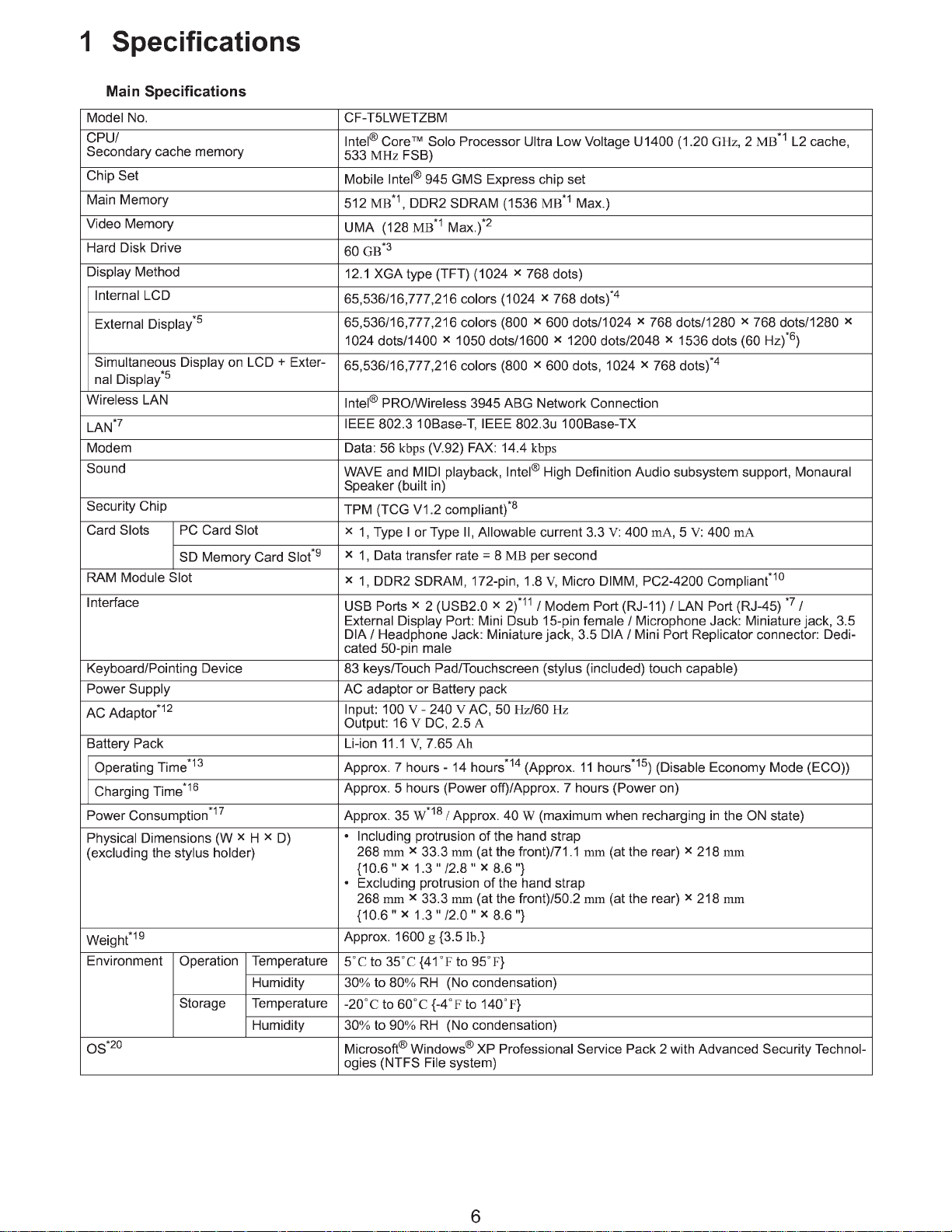
1. Specifications 6
2. Names and Functions of Parts 8
3. Block Diagram 10
4. Diagnosis Procedure 11
5. Power-On Self Test (Boot Check) 13
6. List of Error Codes <Only when the port replicator is connected> 14
7. Self Diagnosis Test 16
8. Wiring Connection Diagram 21
9. Disassembly/Reassembly 22
10. Exploded View 74
11. Replacement Parts List 78
2 Names and Functions of Parts
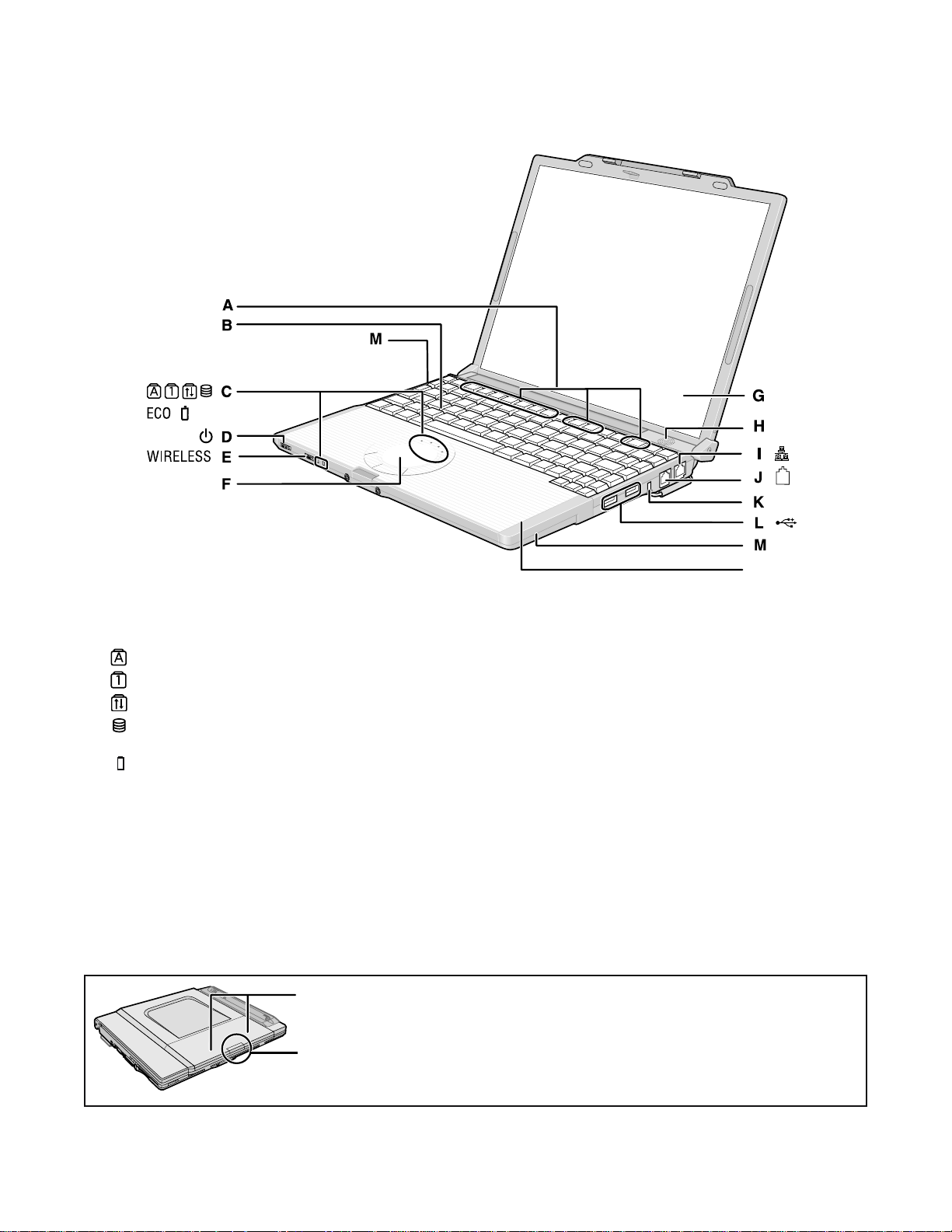
A :Function Key
B :Keyboard
C :LED Indicator
: Caps lock
: Numeric key (NumLk)
: Scroll lock (ScrLk)
: Hard disk drive status
ECO
: Economy Mode (ECO) status
: Battery status
D :Power Switch
page 13
Power Indicator
Off: Power off/Hibernation
Green: Power on
Blinking green: Standby
E : Wireless Switch
<Only for model with wireless LAN/wireless WAN/
Bluetooth>
F : Touch Pad
Wireless WAN Antenna
N
G :LCD/Touchscreen
H :Speaker
I : LAN Port
If the Mini Port Replicator is connected to the computer,
connect the LAN cable to the LAN port on the Mini Port
Replicator. You cannot use the LAN port on the computer.
J : Modem Port
Be sure to use the included modem telephone cable,
and insert the end of the cable with the phyllite core
into the modem port on the computer.
K :Security Lock
You can connect a Kensington cable. Refer to the instruction manual of the cable. The security lock and cable is a
theft prevention device. Matsushita Electric Industrial Co.,
Ltd. will bear no responsibility in the event of theft.
L : USB Ports
M :Wireless LAN Antenna
<Only for model with wireless LAN>
N :Bluetooth Antenna
<Only for model with Bluetooth>
For model with EVDO or without wireless WAN:
The SIM card slot under this cover is not used for this model. Do not open the cover.
For other models:
Refer to the additional instructions.
8
EXT.
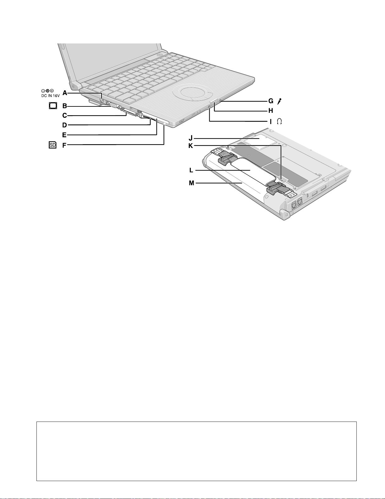
A :DC-IN Jack
B :External Display Port
If the Mini Port Replicator is connected to the computer, connect the external display to the external display port on the Mini Port Replicator. You cannot use
the external display port on the computer.
C :Mini Port Replicator Connector
Connect the Mini Port Replicator (optional).
D :SD Memory Card Slot
E : PC Card Slot
F : SD Memory Card Indicator
Blinking: During access
G :Microphone Jack
A condenser microphone can be used. If other types
of microphones are used, audio input may not be possible, or malfunctions may occur as a result.
When recording in stereo using a stereo microphone:
Double-click in the notification area, click
[Options] - [Properties], and add a check mark for
[Recording], click [OK] - [Options] - [Advanced Controls] - [Advanced], remove a check mark for [Mono
Microphone], and then click [Close].
When using a monaural microphone with a 2-terminal plug:
With the settings outlined above, only audio on the
left track will be recorded.
When monitoring the microphone audio using headphones, sounds on the left track cannot be heard,
regardless of the above settings. This is a result of the
computer s specifications, and is not a malfunction.
H :Latch
I : Headphone Jack
You can connect headphones or amplified speakers.
When they are connected, audio from the internal
speakers is not heard.
J : RAM Module Slot
K :Battery Latches
L : Hand Strap
M :Battery Pack
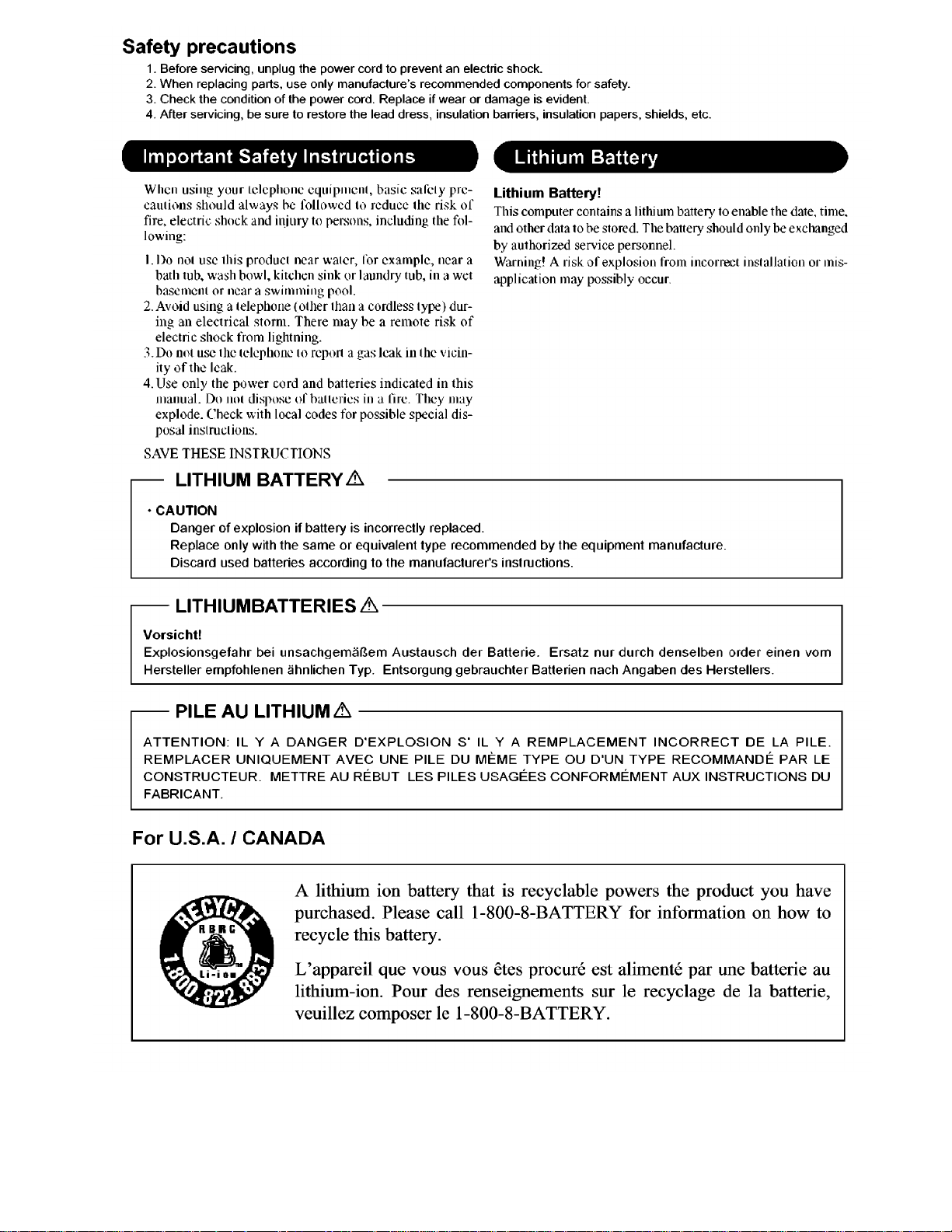
A lithium ion battery that is recyclable powers the product you have purchased.
Please call 1-800-8-BATTERY for information on how to recycle this battery.
L appareil que vous vous Œtes procurØ est alimentØ par une batterie au lithium-ion.
Pour des renseignements sur le recyclage de la batterie, veuillez composer le
1-800-8-BATTERY.
9
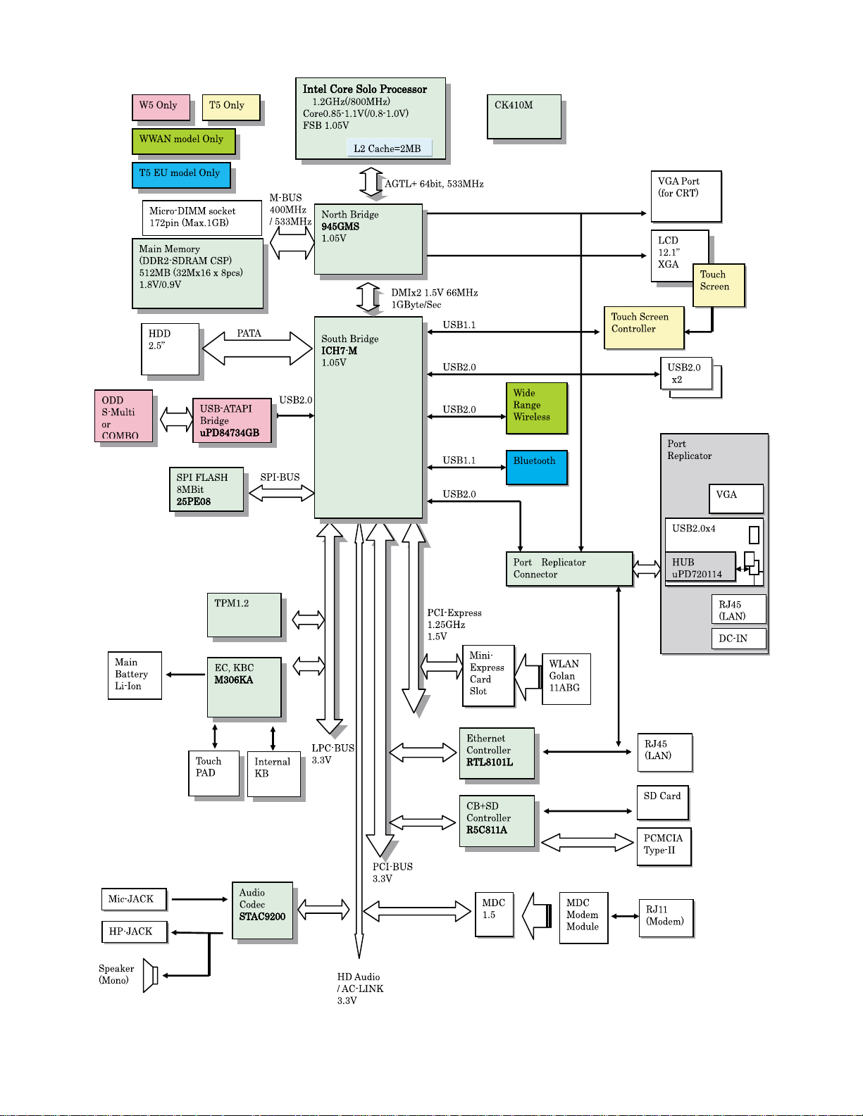
3 Block Diagram
10

4 Diagnosis Procedure
4.1. Basic Procedures
11
4.2. Troubleshooting
f
k
Please take note of the following two points with regard to troubleshooting:
1. Know-how of diagnosis upon occurrence of heavy troubles, e.g. Set cannot be turned ON , Set fails to start , No display on
screen , etc.
2. Explanation of each trouble, mainly symptom of trouble in operation.
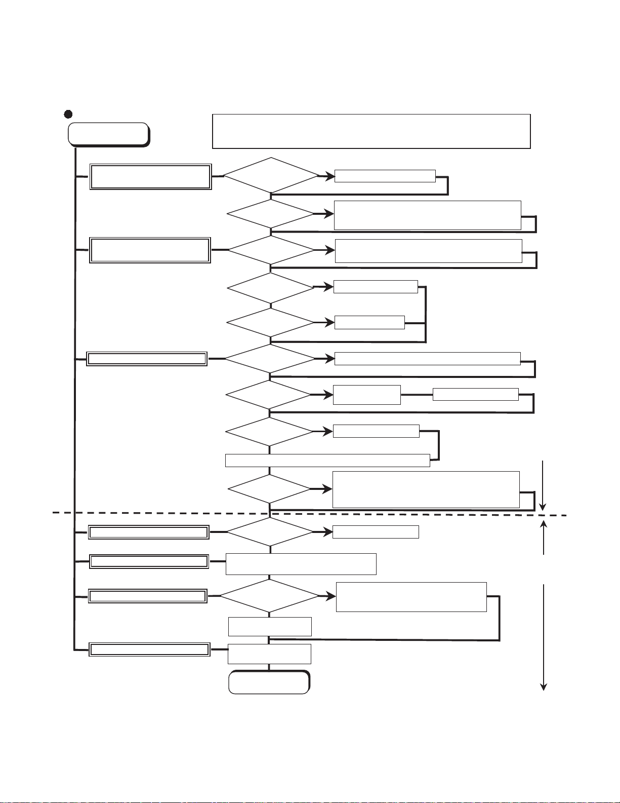
Flow Chart
START
START
Pay attention to the following points when in pursuit of the cause of a troubleshooting.
1. Peripheral apparatus connected with the set should all be removed before operation check.
2. Make sure that cables, boards, etc. are not coming off, and recheck the contact condition.
Set cannot be supplied with current.
Power lamp fails to light up.
Dark display on screen.
Screen fails to display.
Failure in starting
Return set-up utility setpoint to the state of delivery from factory .
Not displayed properly on screen.
Some or all keys cannot be input.
Make sure of contact of K/B connector in use.
Replace keyboard or main board.
CD CALL not practicable.
Starts but operates unstably.
Reinstall HDD.
Replace main board.
AC
Adaptor/Battery
Output voltage
Power lamp
check
Inverter board
LCD back
light lighting
YES
LCD unit
check
OK
BIOS operation
chec
Result of
POST
Set-up utility
starting
OK
HDD access
YES
Main board
check
OK
Trouble
symptoms on some
of CD
YES
Replace main board.
OK
YES
OK
YES
OK
NO
NG
NO
NG
NO
NG
NG
NO
NG
NG
Replace AC Adaptor/Battery
Check contact condition of power input terminal. Replace i
defective.
Check Power SW. Replace if defective.
Replace inverter board.
Check inverter cable continuity. Replace if defective
Replace LCD back light.
Replace LCD unit.
Replace main board (Check fuse at power source).
Refer to POST
error code table.
Replace main board.
Check HDD cable connection and continuity.
Replace if defective.
Replace HDD & Reinstall.
Replace main board.
Replace main board
Check if there are any flaws on CD media. Since
NO
flaws may appear on specific media, CD media
can be defective.
Replace main board.
Heavy trouble e.g.,
Set cannot be turned
ON , Set fails to start ,
No display on
screen , etc.
Each kind of
trouble in
operation.
START
END
12
5 Power-On Self Test (Boot Check)
Outline of POST
The set has a boot check function called POST (Power-On Self Test) in it.
The condition of the main body is diagnosed by checking
Start .............Test begins automatically when power switch is set to ON.
Normal finish .....After memory checking, a beep sound is issued once and the set is placed into automatic stop.
Note: If no error occurs, nothing is displayed. (No display of OK, etc.)
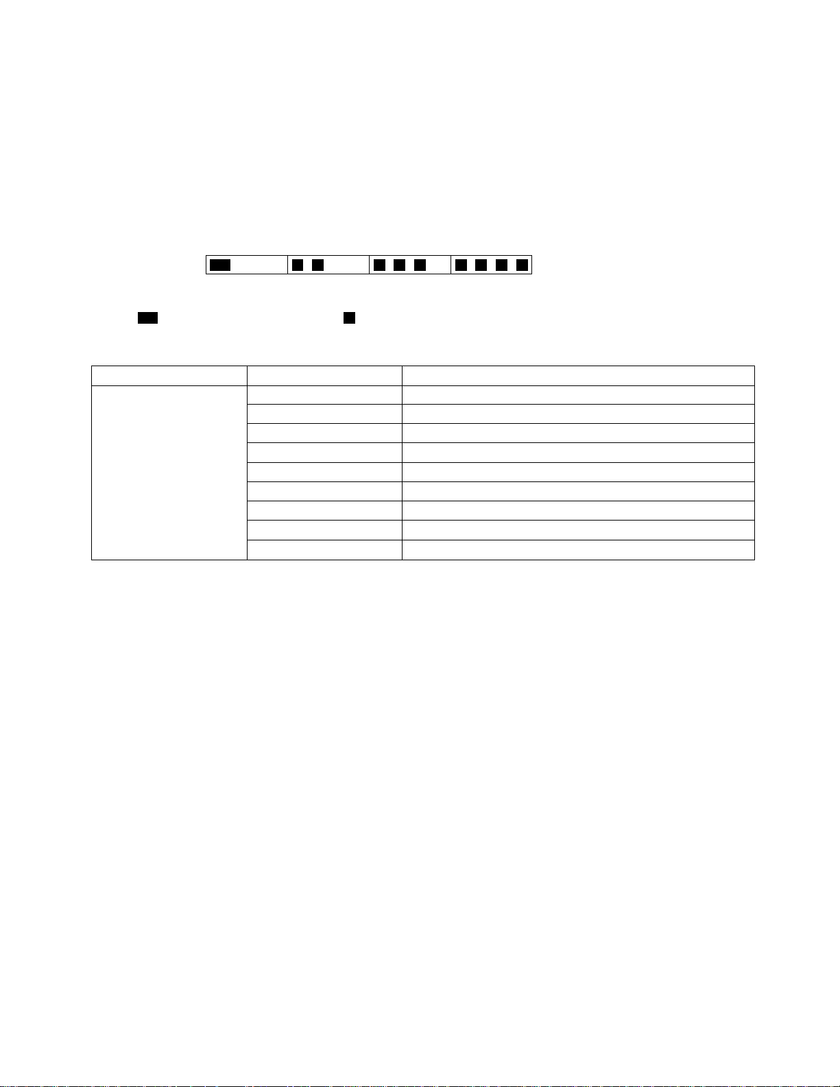
Error Diagnosis by Checking Beep Signal Sound
The beep sound is as follows:
(Length of bar shows length of sound.)
beep sound or error code.
(1 (long sound) -2-3-4)
= long sound (about 0.4 sec.),
Table of errors classified by beep sounds
Diagnosis Beep signal sound Error message
Main board
(Note) A beep sound is also issued in case of other I/O trouble.
1(long sound)-2 BIOS ROM error
1-2-2-3
1-3-1-1
1-3-1-3
1-3-4-1
1-3-4-3
1-4-1-1
= short sound (about 0.2 sec.), Length between sounds is about 0.1 sec.
BIOS ROM error
RAM error
Keyboard controller error
RAM error
RAM error
RAM error
BIOS ROM error2-1-2-3
Occurrence of unexpected offering2-2-3-1
13

6 List of Error Codes <Only when the port replicator is connected>
The following is a list of the messages that BIOS can display. Most of them occur during
POST. Some of them display information about a hardware device, e.g., the amount of memory
installed. Others may indicate a problem with a device, such as the way it has been configured.
Following the list are explanations of the messages and remedies for reported problems.
If your system displays one of except the messages marked below with an asterisk (*), write
down the message and contact Panasonic Technical Support. If your system fails after you
make changes in the Setup menus, reset the computer, enter Setup and install Setup defaults
or correct the error.
0200 Failure Fixed Disk
Fixed disk in not working or not configured properly. Check to see if fixed disk is attached
properly. Run Setup. Find out if the fixed-disk type is correctly identified.
0210 Stuck key
Stuck key on keyboard.
0211 Keyboard error
Keyboard not working.
0212 Keyboard Controller Failed
Keyboard controller failed test. May require replacing keyboard controller.
0213 Keyboard locked - Unlock key switch
Unlock the system to proceed.
0230 System RAM Failed at offset : nnnn
System RAM failed at offset nnnn of in the 64k block at which the error was detected.
0231 Shadow RAM Failed at offset : nnnn
Shadow RAM failed at offset nnnn of the 64k block at which the error was detected.
0232 Extended RAM Failed at offset : nnnn
Extended memory not working or not configured properly at offset nnnn.
0250 System battery is dead - Replace and run SETUP
The CMOS clock battery indicator shows the battery is dead. Replace the battery and run Setup
to reconfigure the system.
*0251 System CMOS checksum bad - Default configuration used
System CMOS has been corrupted or modified incorrectly, perhaps by an application program
that changes data stored in CMOS. The BIOS installed Default SETUP Values. If you do not
want these values, enter Setup and enter your own values. If the error persists, check the system
battery or contact Panasonic Technical Support.
0260 System timer error
The timer test failed. Requires repair of system board.
0270 Real time clock error
Real-time clock fails BIOS test. May require board repair.
*0280 Previous boot incomplete - Default configuration used
Previous POST did not complete successfully. POST loads default values and offers to run
Setup. If the failure was caused by incorrect values and they are not corrected, the next boot
will likely fail. On systems with control of wait states, improper Setup settings can also terminate POST and cause this error on the next boot. Run Setup and verify that the wait-state
configuration is correct. This error is cleared the next time the system is booted.
0281 Memory Size found by POST differed from EISA CMOS
Memory size found by POST differed from EISA CMOS.
14

02D0 System cache error - Cache disabled
Contact Panasonic Technical Support.
02F0: CPU ID:
CPU socket number for Multi-Processor error.
02F4: EISA CMOS not writable
ServerBIOS2 test error: Cannot write to EISA CMOS.
02F5: DMA Test Failed
ServerBIOS2 test error: Cannot write to extended DMA (Direct Memory Access) registers.
02F6: Software NMI Failed
ServerBIOS2 test error: Cannot generate software NMI (Non-Maskable Interrupt).
02F7: Fail - Safe Timer NMI Failed
ServerBIOS2 test error: Fail-Safe Timer takes too long.
device address Conflict
Address conflict for specified device.
Allocation Error for: device
Run ISA or EISA Configuration Utility to resolve resource conflict for the specified device.
Failing Bits : nnnn
The hex number nnnn is a map of the bits at the RAM address which failed the memory test.
Each 1 (one) in the map indicates a failed bit. See error 230,231 or 232 for offset address of the
failure in System, Extended or Shadow memory.
Invalid System Configuration Data
Problem with NVRAM (CMOS) data.
I/O device IRQ conflict
I/O device IRQ conflict error.
Operating System not found
Operating system cannot be located on either drive A: or drive C:. Enter Setup and see if fixed
disk and drive A: are properly identified.
Parity Check 1 nnnn
Parity error found in the system bus. BIOS attempts to locate the address and display it on the
screen. If it cannot locate the address, it displays ????. Parity is a method for checking errors
in binary data. A parity error indicates that some data has been corrupted.
Parity Check 2 nnnn
Parity error found in the I/O bus. BIOS attempts to locate the address and display it on the
screen. If it cannot locate the address, it displays ????.
Press <F1> to resume, <F2> to Setup
Displayed after any recoverable error message. Press <F1> to start the boot process or <F2> to
enter a Setup and change the settings. Write down and follow the information shown on the
screen.
Troubleshooting
15
7 Self Diagnosis Test
As for the self-diagnosis test(PC-Diagnostic utility) to use this model, a standard test and the
enhancing test by the module of the main body building in are possible.
Notes
1. Beginning of self-diagnosis test
1-1. Setting of content of setup
The power supply of the computer is turned on.
1.
" F2 " is pushed on the screen of "Panasonic" while " press <F2 to enter Setup> " is displayed.
2.
The setup utility starts and then takes notes of the content of the BIOS setup of present set.
3.
" F9 " is pushed, " Yes" is selected on the screen of " Is the default value loaded? ", and " Enter"
4.
is pushed.
" F10 " is pushed.
5.
" Yes" is selected on the screen of the setup confirmation, and " Enter" is pushed.
6.
The computer starts automatically.
7.
Attention
If the device which can be set is set to "Invalidity" by "Advanced" or "Security" menu, becomes an
error by "PC-Diagnostic utility".
(It is judged that the device which can be set to "Invalidity" by "Main" menu such as "Flat pad" is
normal if the controller operates normally though sets to "Invalidity" by the setup. )
In the model with built-in DVD of the USB connection, even if DVD is normal, becomes an error if
legacy USB is set to "Invalidity"
To skip BIOS password
Use <Ctrl>+<F10> key to skip BIOS password or authentication of fingerprint.
This key is only for entering DIAG mode. Not available to boot the computer.
If customer set "HDD Lock", the DIAG program cannot perform HDD test.
*This key is for service purpose only. Do not disclose this information to unrelated others.
1-2. When you execute an automatic test
1.
"Ctrl" + "F7" is pushed while the "Panasonic" start screen is displayed after the computer is started.
2.
The test of all devices begins automatically by "PC-Diagnostic utility"’s starting.
Attention
It is a test which the customer who bought PC can execute. (As for HDD, the enhancing test is also
possible.)
A flat pad does not work for a while after starting "PC-Diagnostic utility".
The movement of a flat pad might become abnormal If after RAM begins from the CPU/System
test, a flat pad will be operated in about 30 seconds. In that case,restarts pushing"Alt" + "Ctrl" +
"Del" key. Or, please start "PC-Diagnostic utility" again after doing the power supply switch in the
slide, and turning off the power supply.
1-3. When you execute the enhancing test
Please let me discontinue diagnosing clicking to end an automatic test.
1.
Please click on the character of "D" "PC-Diagnostic utility" on the screen while pushing both of right
2.
"Shift" and left "Shift" keys.
D
All devices which can select the enhancing test make the setting of the enhancing test possible.
3.
The district device is made"FULL" display (enhancing test).
4.
The test begins clicking .
5.
*Please refer to item 4 for the error result of each test and the division of the breakdown part.
16
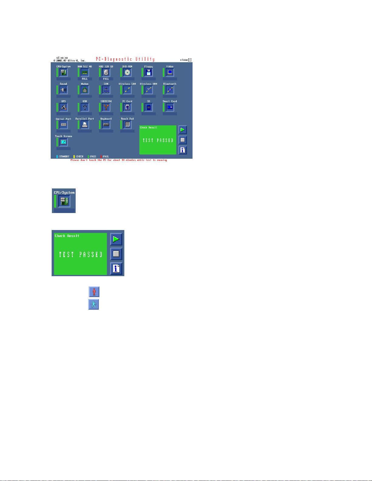
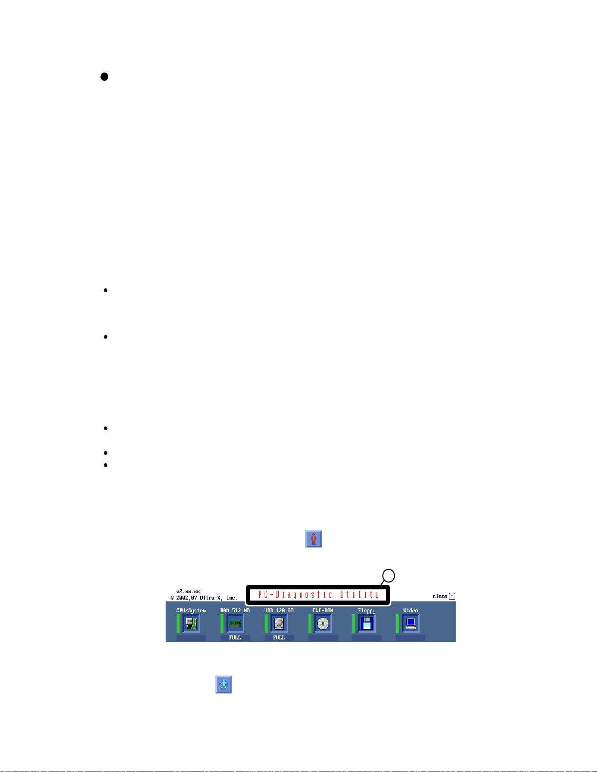
2. Operation of PC-Diagnostic Utility
-Only the device which can be inspected on the entire screen is displayed.
-The item does not appear when the device of wireless LAN etc. is not physically connected.
-The movement of the item must use an arrow key or a flat pad.
-As for the device under the diagnosis, blue and yellow are alternately displayed at the left of the icon.
- The diagnosis result of the device greens at the left of the icon when it is normal, and becomes red when
abnormal.
-When the test of all devices ends, the test result is displayed under the right of the screen.
-Please click while diagnosing when being stop on the way by the time the test of all devices ends.
-Please click when you restart "PC-Diagnostic utility".
*Each device is tested from the beginning, and it is not possible to restart on the way.
17
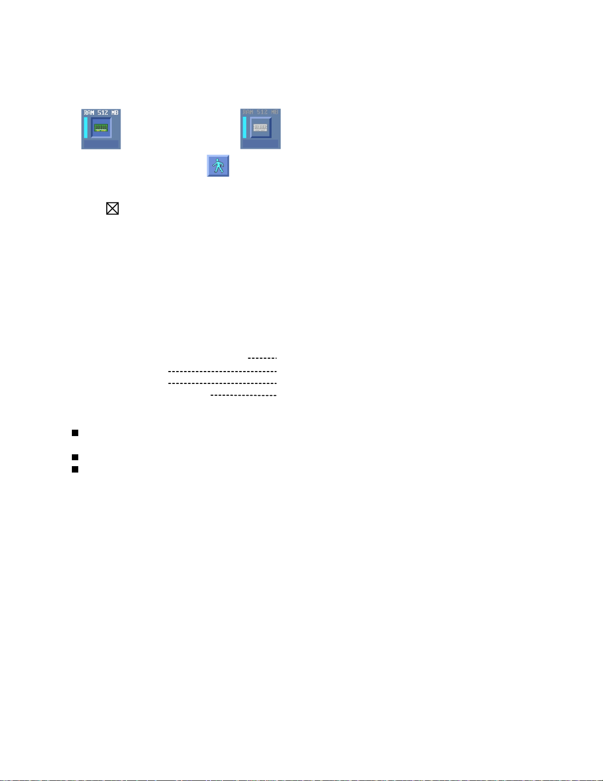
2-1. Selection of tested device
-To test only a specific device, "Test" and "Do not test" of each device can be selected.
-The device which can select the enhancing test changes in order of "The standard is tested" and "Do not
test" whenever the device icon is clicked.
Start the standard test
Please begin testing clicking if the selection of the tested device ends.
Do not test
2-2. "PC-Diagnostic utility" End method
When of "Close" on the right of the screen is clicked, the computer reactivates automatically. Or, the
power supply switch is done in the slide and the power supply is turned off.
2-3. The content of the setup is returned to the setting of the user
Turned on the computer.
1.
"F2" is pushed on the screen while "Press<F2>to enter Setup" is displayed of "Panasonic".
2.
Push "F10", and on the screen of "Is the change in the setting preserved and do end?"and then "Yes"
3.
is selected, and "Enter" is pushed.
The computer reactivates automatically.
4.
The end option is chosen by the start menu, and the power supply of the computer is turned off.
5.
Standard at test time
All devices other than RAM and HDD
RAM standard test
HDD standard test
HDD enhancing test (60GB)
about 1 minute
1 - 2 minutes
2 - 3 minutes
about 40 minutes
Ex.The standard when the standard <all device> is tested becomes 1+2+3=6 minutes.
There is greatly a difference from RAM test when the memory is increased according to the performance of the memory occasionally.
Moreover, when the main body of PC under the test is a high temperature, it occasionally takes time.
There is greatly a difference from HDD according to the performance of the drive occasionally.
18
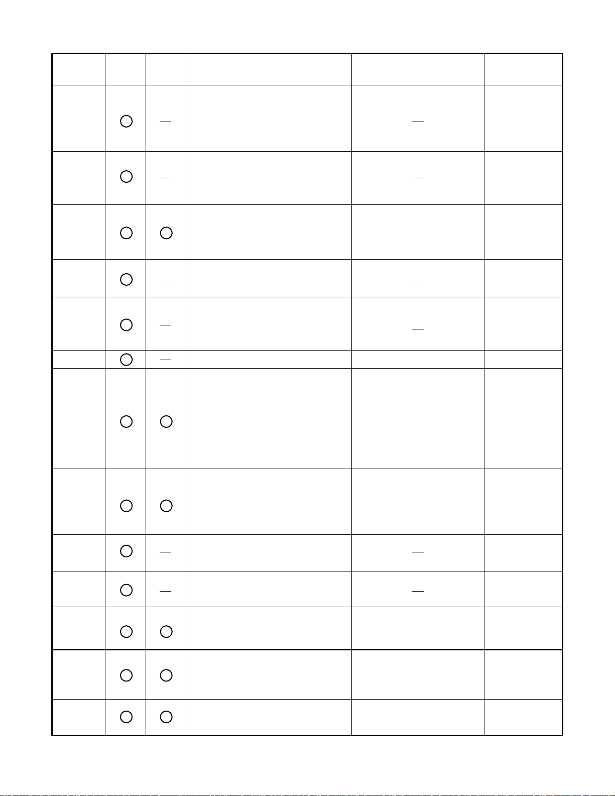
7.1. Test Item and Division of trouble
Test item Stanard
CPU /
SYSTEM
RAM All memory space is tested in a spe-
HDD The record area frequently accessed
MODEM It is confirmed not to find abnormality
Wireless
LAN
Enhancing
Content of standard test Content of enhancing test
CPU is shifted to protected mode, and
"Violation of the paging", "Operation of
the violation of a privileged instruction", and DMA, INT, TIMER, and the
RTC operation are confirmed.
cial memory access pattern based on
"R.S.T . technology".
with Microsoft Windows XP to test in
about two minutes regardless of
points of HDD is emphatically tested.
in the AC97 modem controller.
It is confirmed not to find abnormality
in the Wireless LAN modem controller.
Place with possibili-
ty of breakdown
CPU /
Main board
Memory / Mainboard
All record area is tested. HDD /
Mainboard /
Cable /
Connector
MODEM/ Mainboard
Wireless LAN
board /
Connector /
Mainboard
Sound
USB It is confirmed not to find abnormality
LAN It is confirmed not to find abnormality
PC Card It is confirmed not to find abnormality
SD It is confirmed not to find abnormality
Keyboard It is confirmed not to find abnormality
*5
in the USB controller.
*1
in the LAN controller.
*2
in the CardBus controller.
in the SD controller.
*3
in keyboard controller’s keyboard interface.
It is confirmed not to find abnormality in the wiring between the USB controller and
the connector by confirming
the connection of the USB
equipment connected with the
USB connector.
It is confirmed not to find abnormality in the wiring between the controller and the
connector by connecting to
HUB with LAN cable.
The key is actually input, and
the operation is displayed on
the screen.
Mainboard /
Connector
Mainboard /
Connector
Mainboard
Mainboard
Mainboard /
Keyboard
Touch Pad
DVD-ROM
Whether keyboard controller’s mouse
*4
interface operates normally is confirmed.
*6
The drive is normally reset, and it is
accessible is confirmed.
19
The operation is actually displayed on the screen by operating the touch pad.
It is confirmed to be able to
read media normally.
Mainboard /
Touch Pad
Mainboard /
Touch Pad
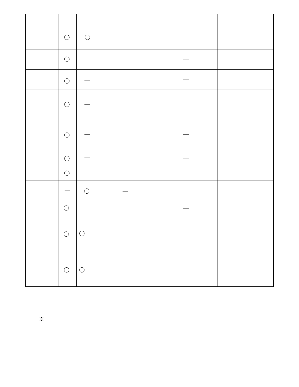
Test Item
Touch Screen
Bluetooth
Wireless WAN
Floppy
Video
GPS
IEEE1394
Express Card
Smart Card
Serial Port *7
Parallel Port *8
*1
Please connect the USB device with the port (USB connector) which wants to test before the tests.
*2
Please connect LAN port with LAN HUB with LAN cable before the tests.
The operator actually inputs the key, and the operator judges PASS/FAIL of the test.
*3
The operator actually operates the mouse, and the operator judges PASS/FAIL of the test.
*4
It is not abnormal though the sound is emitted from the speaker while testing.
*5
*6
Please set DVD/CD media in the drive before the tests.
*7 Please set a Special Loop Back Connector Tool at serial connector for Enhanced Test.
(This Connector Tool is same as the one used before.)
*8 Please set a Special Loop Back Connector Tool at parallel connector for Enhanced Test.
(This Connector Tools is same as the one used before.)
Standard Enhanced
When the test result is PASS, trouble is thought by not hearing of the sound under the test from
the speaker and the headphone by the wiring of the audio output system.
Content of Standard Test Content of Extend Test
It is confirmed not to find
abnormality in the USB
connection of Touch Screen.
This test cannot find
abnormality of Touch Screen.
It is confirmed not to find
abnormality in the connection
of Main board and Bluetooth
module.
It is confirmed not to find
abnormality in the connection
of Main board and Wireless
WAN module.
It is confirmed not to find
abnormality in the legacy FD
drive.
This test cannot find
abnormality of mechanical
breakdown. (e.g.. Head, Motor)
It is confirmed not to find
abnormality in access to
VRAM with VESA.
The PC which uses main
memory as VRAM may fail with
main memory failure.
It is confirmed not to find
abnormality in the connection
of Main board and GPS
It is confirmed not to find
abnormality in the IEEE1394
controller.
It is confirmed not to find
abnormality in the Smart Card
controller.
It is confirmed not to find
abnormality of Super I/O
UART function.
This test cannot find lack of
wiring between Super I/O and
Serial Connector.
It is confirmed not to find
abnormality of Super I/O
parallel function.
This test cannot find lack of
wiring between Super I/O and
Parallel Connector.
Perform Touch Screen
functionality practically.
Operator has to judge
PASS/FAIL with test result.
It is confirmed not to find
abnormality in the wiring
between Chipset and Express
Card.
It is confirmed not to find
abnormality in the wiring
between Super I/O and Serial
Connector.
This test cannot find failure of
cable characteristic and device
problems.
It is confirmed not to find
abnormality in the wiring
between Super I/O and
Parallel Connector.
This test cannot find failure of
cable characteristic and device
problems.
The place with possibility of
breakdown
Main board/
Touch Screen
Bluetooth cable
WWAN cable
FD Drive/
Main board (Super I/O)/
FDD cable
FDD connector
Main board
(Chipset, Graphic
Controller)/
Memory
GPS cable
Main board
(IEEE#394 Controller)
Main board (Chipset)/
Express Card Connector
Main board
(Smart Card Controller)
Main board (Super I/O)/
Serial Connector
Main board (Super I/O)/
Parallel Connector
20

8 Wiring Connection Diagram
LCD Unit
and
Touch Screen
TS Board
Inverter Board
Battery Pack
CN601
Connection by Cable
Direct connection Connectors
Parts on Bottom Side
Antenna Board
(R)
Wireless LAN
Module
Antenna Board
(L)
Connection Cable
1 LCD Cable DFJS1050ZA
2 SP Cable DFJS962ZA
3 Antenna PCB-L N1ZYYY000002
4 Antenna PCB-R N1ZYYY000003
5 MODEM Cable DFJS973ZB
6 LAN Cable DFJS958ZB
7 PAD FFC DFJK12U112BB
8 FPC Unit,HDD DL3UP1443AAA
9 DC-IN Cable DFJS1020YA
10 USB Cable DFJS980ZA
WWAN Antenna Board
CN1501
WWAN Antenna Board
CN26
(R)
WWAN
(L)
SIMM
Card
Speaker
Keyboard
DC IN
MODEM
JACK
SD Card
PCMCIA
SLOT
VGA
MDC
MODEM
CN12
CN10
CN600
CN18
CN13
POWER SW
CN603
CN11
SW6
DIM memory
CF-BAW0512U
(PC2-4200)
Main Board
CN2
W-LAN SW
(Option)
SW7
CN19
CN14
LAN
CN28
CN16
JK1
Headphone
CN23
CN3
CN21
CN15
CN4
JK2
Mic
Lithium Battery
HDD
2-Port Board
CN1051
CN1053
CN1052
Touch Pad
USB
USB
21
9 Disassembly instructions
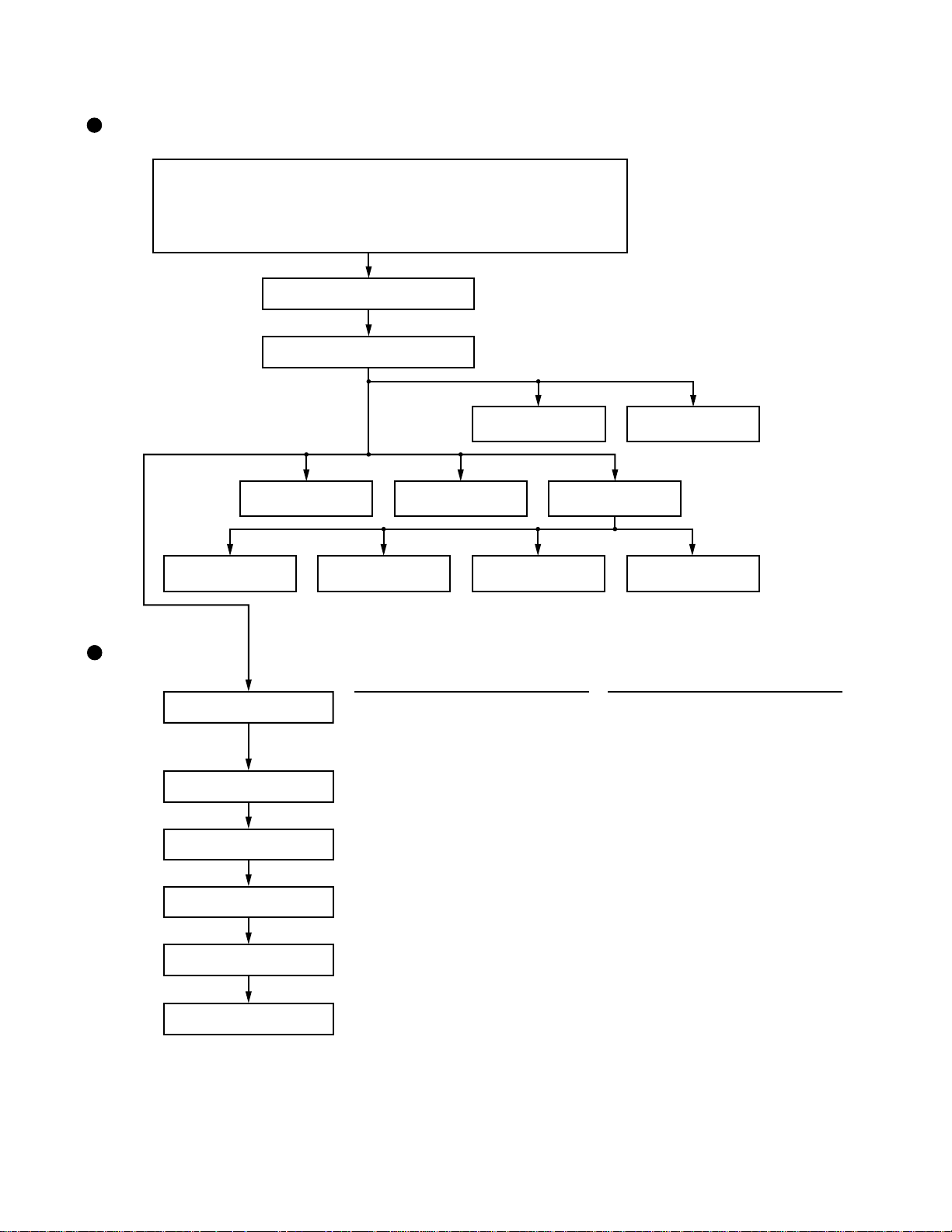
9.1. Disassembly Flow Chart
Main Unit
9.2.1.
Preparation
1. End the Windows.
2. Turn off the Power, and then remove the AC Adaptor or Battery Pack.
3. Remove any optional DIMM Memory Cards or PCMCIA Cards.
4. Remove any other peripherals or Connected Devices.
9.2.2.
Keyboard
9.2.3.
Top Case
9.2.4. 9.2.5.
Touch Pad
LCD Open Knob
/Speaker
9.2.9 . 9.2.10.
Antenna Board
(L, R) / DC-IN
Display Unit
9.2.13.
9.2.14.
9.2.15.
LCD Unit / LCD Rear
9.2.16.
9.2.17.
9.2.18.
9.2.6.
USB Board
LCD Unit
Hinge Cover
Inverter Board
WWAN Antenna
(MAIN), (SUB)
WWAN Board
9.2.7. 9.2.8.
HDD Main Board
9.2.11. 9.2.12.
W-LAN Board
Main replaceable parts
9.2.1.
9.2.2.
9.2.3.
9.2.4.
9.2.5.
9.2.6.
9.2.7.
- Battery Pac
- DIMM Cover
- AC Adaptor
- Kyeboard
- Top Case
- Antenna Cover (R)
- Touch Pad
- Pad Cover
- PAD Button
- PAD FPC
- LCD Knob
- Spealer
- USB Board
- USB Cable
- HDD
- HDD Case
- FPC Unit, HDD
MDC MODEM
Card Bas ejector
9.2.8.
9.2.9.
9.2.10.
9.2.11.
9.2.12.
9.2.13.
9.2.14.
9.2.15.
9.2.16.
9.2.17.
9.2.18.
- Main Board
- Antenna Board (L, R)
- DC-IN
- W-LAN Unit
- MDC MODEM
- Card Bas ejector
- LCD Unit
- Hinge Cover
- Hinge (L, R)
- LCD Unit
- LCD Rear
- LCD Front TP
- Inverter Board
- LCD Cable
-WWAN Antenna (MAIN), (SUB)
-WWAN Antenna Cover
-WWAN Board
22
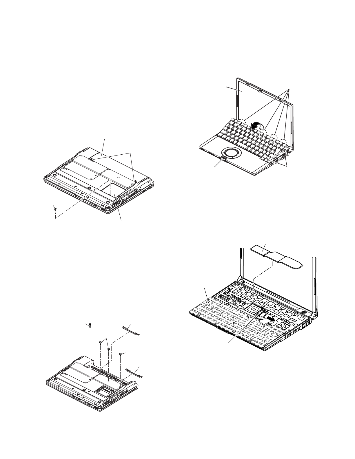
9.1. Disassembly lnstructions
9.2.1. Preparation
Attention:
Before disassembly, be sure to perform the
following steps.
1. End the Windows.
2. Turn off the power and then remove the AC adap-
tor.
3. Slide the hooks (A) and then remove the battery
pack.
4. Remove the screw (A) and then remove the DIMM
cover.
(Remove if the DIMM memory is equipped with)
Screw (A) : XSB2+4FNL (N16)
Baattrey Pack
Hook (A)
4. Remove the 6 hooks (B).
5. Open the keyboard from LCD side and then turn it
inside out on the top case.
Note:
It can remove with the keyboard hook plate.
LCD Unit
Hook(B)
Screw (A)
DIMM Cover
9.2.2. Removing the Keyboard
Preparation : perform the section 9.2.1.first.
1. Remove the 4 screws (B).
Screw (B) : DXQT2+E12FNL (N11)
2. Remove the 2 keyboard hook plates,and then
remove the hook of back side of keyboard with
screw driver.
Screw (B)
Keyboard Hook Plate
Screw (B)
LCD Knob
Hook(B)
6. Remove the heat spreader from buttom of the
keyboard.
7. Remove the keyboard FFC from the connector
(CN15) and then remove the keyboard.
Heat Spreader
KeyBoard
Screw (B)
Keyboard Hook Plate
3. The LCD unit is opened up to about 90 °by operat-
ing the LCD knob.
CN15
23
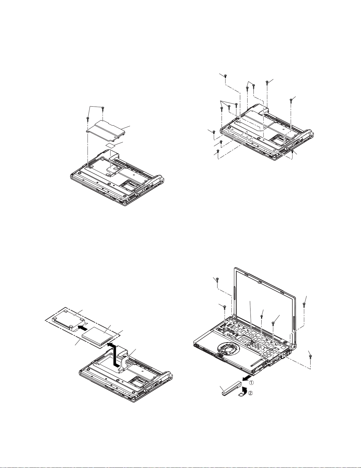
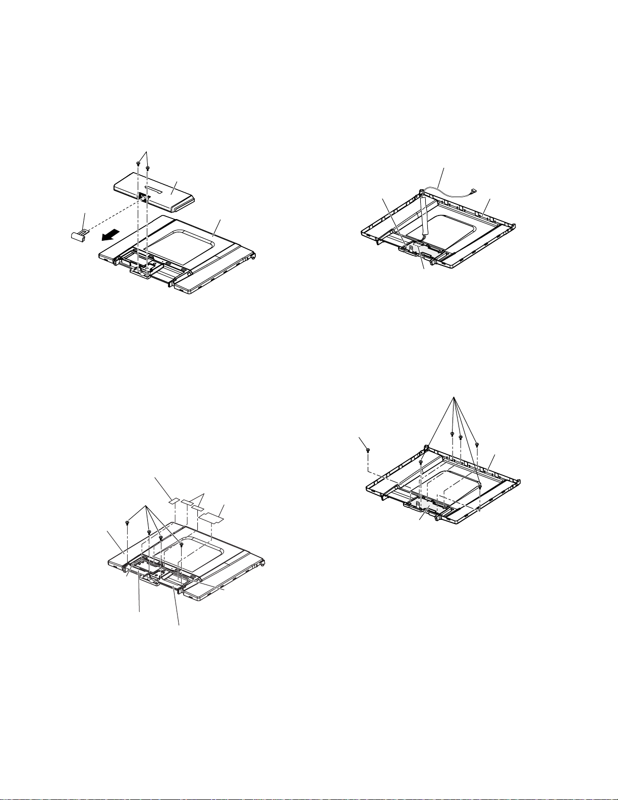
9.2.3. Removing the HDD
Preparation : perform the section 9.2.1., 9.2.2.
first.
1. Remove the 2 screws (C) and then remove the
HDD cover.
Screw (C) : DFHE5025XA (N1)
2. Peel off the tape from HDD FPC.
Tape : TPD-X0033A (S1001)
9.2.4. Removing the Top Case
Preparation : perform the section 9.2.1.,9.2.2.
first.
1. Remove the 7 screws (D) and screws (E).
Screw (D) : DXHM0039ZA (N5)
Screw (E) : DXHM0057ZA (N7)
Screw (E)
Screw (D)
Screw (D)
Screw (C)
HDD Cover
Tape
3. Lift up the HDD unit and remove FFCconnector
and then remove the HDD unit.
4. HDD is taken out of the HDD case.
Screw (D)
Screw (E)
Screw (E)
Screw (E)
Screw (D)
Screw (E)
2. Remove the speaker cable from the connector
(CN26).
3. Remove the side cover (R) as slide it to this side.
4. Remove the 1 screw (F), 3 screws (G) and 2
screws (H) from top case and then remove the top
case.
Screw (F) : DXHM0056ZA (N6)
Screw (G) : DXQT2+E6FNL (N12)
Screw (H) : DXQT26+D8FCL (N14)
Note :
Please don't bend pins of HDD FPC connector
when the HDD is removed.
HDD Case
HDD
FFC Connector
HDD Unit
HDD FFC
Screw(L)
Screw(K)
Side Cover(R)
CN26
Speaker Cable
Screw(J)
Screw(L)
Screw(K)
Screw(K)
24
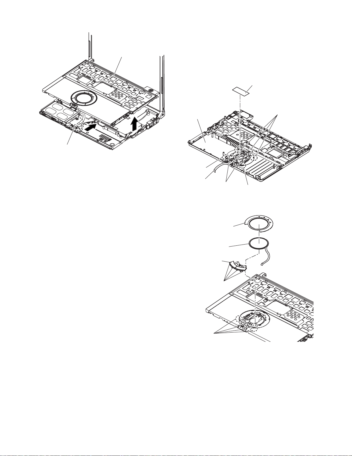
5. Lift up the top case and remove the pad FFC and
then remove the top case.
Top Case
9.2.5. Removing the Touch Pad
Preparation : perform the section 9.2.1., 9.2.2.
and 9.2.4. first.
1. Peel off the tape.
Tape : DFHP7140ZA (K37)
2. Depress to center the 6 hooks of the pad cover, (C)
(D) (E) as order.
Tape
Pad FFC
Top Case
Hook(F)
PAD FFC
Hook(E)
Hook(F)
Hook(D)
3. Remove the hook (F) and remove the touch pad.
Pad Cover
Touch Pad
Pad Button
Hook(F)
Hook(F)
25
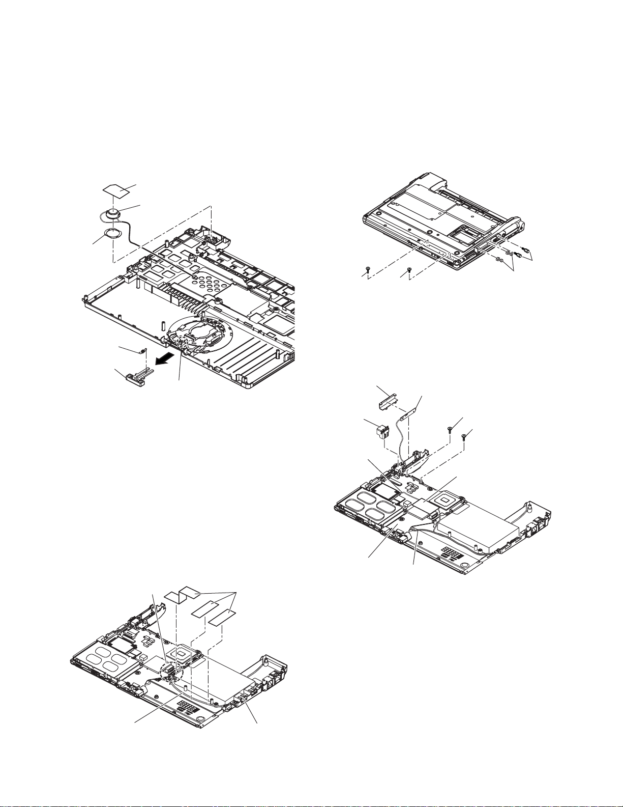
9.2.6. Removing the LCD Knob and the
Speaker
Preparation : perform the section 9.2.1., 9.2.2.
and 9.2.4. first.
1. Remove the latch spring from the top case.
2. Remove the hook of the LCD knob from stopper rib
of the top case.
3. Peel off the4.Peel off the tape on the speaker and
speaker ring and then remove the speaker.
Speaker Box
Speaker
Speaker
Ring
Latch
Spring
LCD Knob
Location of the Spring
9.2.8. Removing the Main Board
Preparation : perform the section 9.2.1., 9.2.2.
and 9.2.4. first.
1. Remove the 1 screw (I ), 1 screw (J), 2 screws (K)
and 2 screws (L ).
Screw (I ) : DXQT2+E10FNL (N10)
Screw (J) : DXQT2+D4FNL (N9)
Screw (K) : DFHE5035ZB (N2)
Screw (L) : K1YE50000022 (N1003)
Screw (K)
Screw ( I )
Screw (J)
2. Remove the 2 screws (M).
Screw (M) : DXQT2+E6FNL (N12)
3. Remove the modem cable from the MDC modem.
4. Remove the side cover (L) from the bottom case.
5. Remove the DC jack holder on the DC-IN jack.
Side Cover (L)
Antenna Board (L)
Screw (L)
9.2.7. Removing the USB Board
Preparation : perform the section 9.2.1., 9.2.2.
and 9.2.4. first.
1. Peel off the tapes and RJ cable sheet for clamp the
USB cable.
Tape : TPD-X0033A (S1001)
RJ Cable Sheet : DFHR3C13ZA (K53)
2. Remove the connector (CN23) on the main board.
3. Remove the USB board from the bottom case.
CN23
Tape
DC Jack
Holder
Modem Cable
Main Board
Screw (N)
Screw (N)
Tape
LAN Cable
USB Cable
2-Port USB Board
26
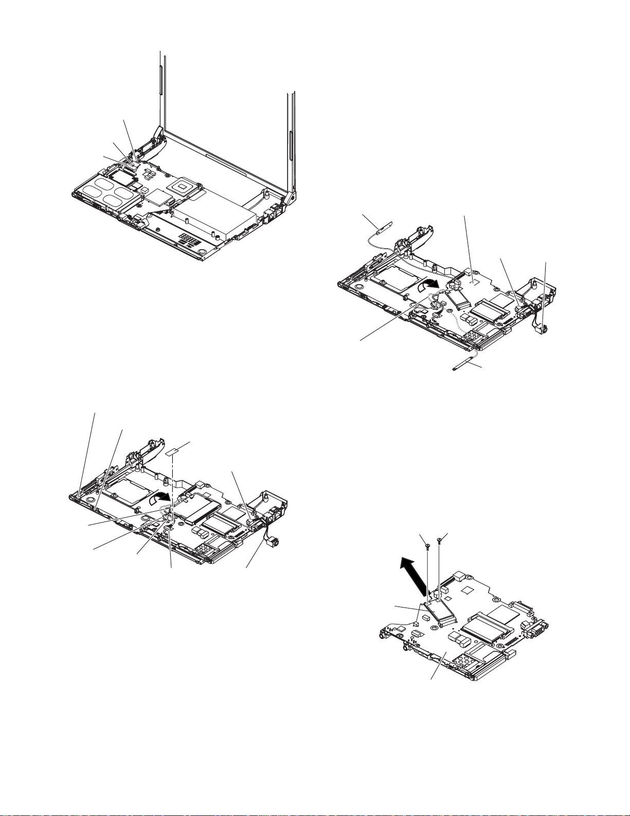
6.Remove the LCD cable connectors (CN10,CN11).
LCD Cable
CN10
CN11
9.2.9. Removing the Antenna
Board (L,R) and the DC-IN Cable
Preparation : perform the section 9.2.1., 9.2.2.,
9.2.4. and 9.2.8. first.
1. Remove the antenna cable (L) from the main
terminal and the antenna cable (R) from the AUX
terminal and then remove the antenna board (L, R)
from the bottom case.
2. Remove the DC-IN cable (CN600) from the main
board.
7. Turn it to arrow and remove the lithium battery
connector (CN3) and HDD FPC connector (CN4).
8. Peel off the tape from LAN cable and then remove
the LAN cable connector (CN16).
Tape : TPD-X0033A (S1001)
9. Remove the main board.
Power Knob
LAN SW Knob
Tape
CN600
Antenna Board(L)
Antenna Cable(R)
Antenna Cable(L)
CN600
Antenna Board(R)
DC-IN
Cable
9.2.10. Removing the Wireless LAN
Module
reparation : perform the section 9.2.1., 9.2.2.,
9.2.4. and 9.2.8. first.
1. Remove the 2 screws (N) and then remove the
Wireless LAN module.
Screw (N) : DXQT2+D25FNL (N8)
LAN
Cable
Lithium Battery
Cable
CN3
CN16
DC-IN Cable
27
Screw (L)
Wireless LAN
Module
Screw (L)
Main Board
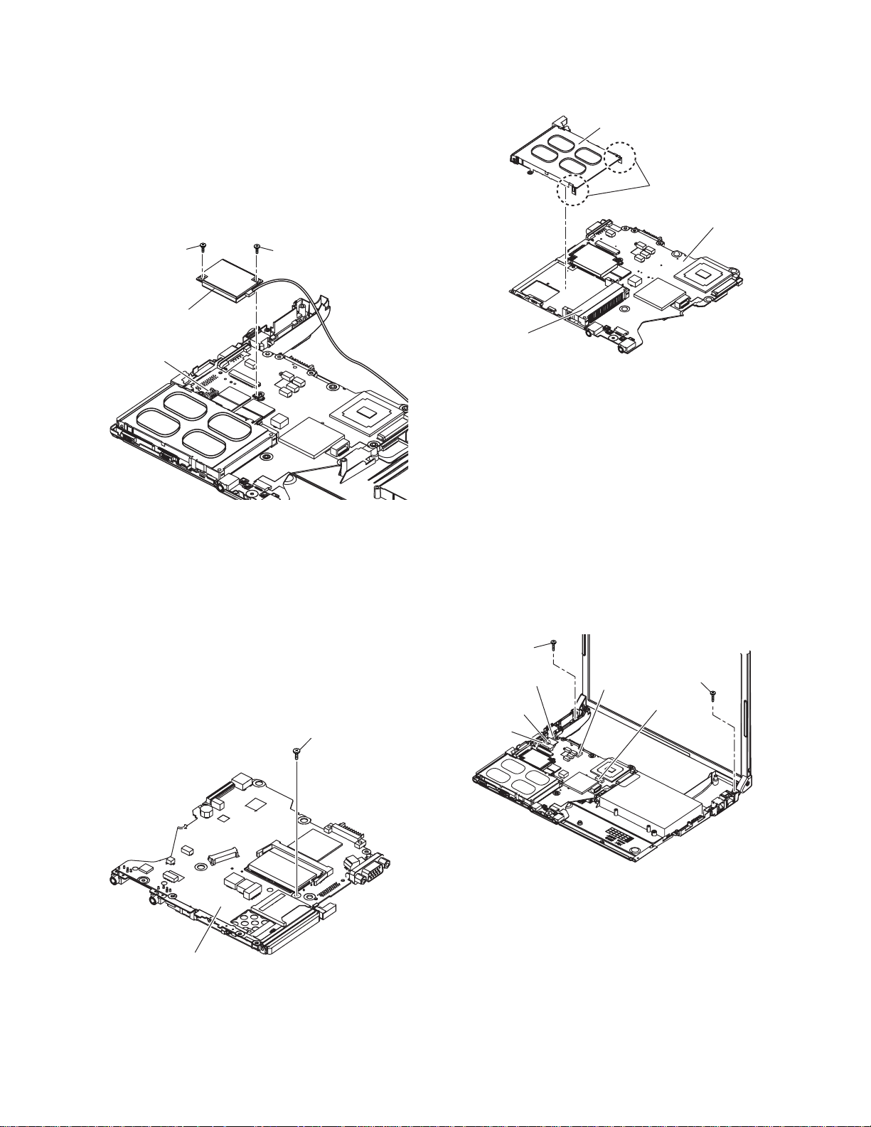
9.2.11. Removing the MODEM
Preparation : perform the section 9.2.1., 9.2.2.,
9.2.4. and 9.2.8. first.
1. Remove the 2 screws (O).
Screw (O) : DXQT2+D25FNL (N8)
2. Remove the MODEM from main board connector
(CN18) as vertical.
Screw (O)Screw (O)
Modem
CN18
9.2.12. Removing the Card Bus Ejector
Preparation : perform the section 9.2.1., 9.2.2.,
9.2.4. and 9.2.8. first.
1. Remove the 1 screw (P) from connection side of
wireless LAN.
Screw (P) : DFHE5025XA (N1)
Screw (Q)
2.Turn to the card bus ejector side.
3. Remove the 2 hooks (G) from the connector
(CN14).
Card Bus Ejector
Hook (G)
Main Board
CN14
9.2.13. Removing the LCD Unit
Preparation : perform the section 9.2.1., 9.2.2.
and 9.2.4. first.
1. Remove the 2 screws (Q).
Screw (Q) : DXQT26+D5FNL (N13)
2. Remove the LCD cable from the connector (CN11)
of the main board.
3. Remove the inverter cable from the connector
(CN10).
4. Disconnect the connectors (CN603, CN28) of the
main board.
Screw (Q)
LCD Cable
CN11
CN603
CN10
Screw (Q)
CN28
Main Board
28
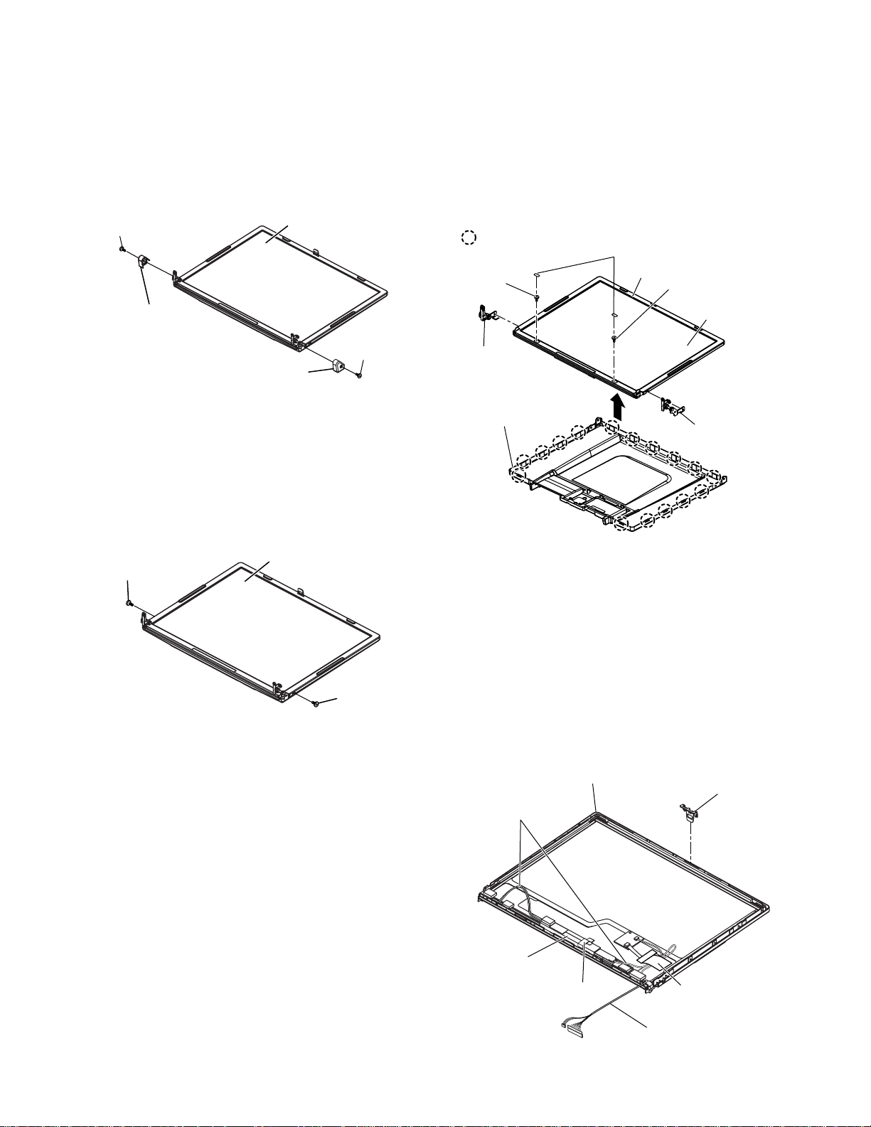
9.2.14. Removing the Hinge Cover
Preparation : perform the section 9.2.1., 9.2.2.,
9.2.4. and 9.2.13. first.
1. Remove the 2 screws (R) and then remove the
hinge cover (L, R).
Screw (R) : DRHM0108ZA (N1002)
Screw (R)
LCD Unit
9.2.15. Removing the LCD Unit and the
LCD Rear
Preparation : perform the section 9.2.1., 9.2.2.,
9.2.4. and 9.2.13. to 9.2.14. first.
1. Remove the 2 LCD Ruber and then remove the 2
screws (T).
Screw (T) : DXHM0039ZA (N5)
2. Separate the LCD front and the LCD rear.
3. Remove the hinge (L), (R).
Hook Position
Screw (T)
LCD Ruber
LCD Front
Screw (T)
Hinge Cover (L)
Hinge Cover (R)
2. Remove the 2 screws (S).
Screw (S) : DRHM0076ZA (N1001)
LCD Unit
Screw (S)
Screw (R)
Screw (S)
LCD Unit
HInge (L)
LCD Rear
Hinge (R)
9.2.16. Removing the Inverter
Preparation : perform the section 9.2.1., 9.2.2.,
9.2.4. and 9.2.13. to 9.2.15. first.
1. Remove the LCD cable from the inverter.
2. Peel off the conductive cloth (LCD cable) from the
inverter.
3. Peel off the inverter tape from the inverter.
Inverter tape : DFHR3A95ZA (K49)
3. Remove the inverter with inverter box.
29
LCD High voltage
2pin Wire Rod
Inverter Box
LCD Front
Inverter Tape
LCD Hook
Conductive Cloth
(LCD Cable)
LCD Cable
9.2.17. Removing the WWAN Antenna
Board (MAIN), (SUB)
Preparation : perform the section 9.2.1., 9.2.2.,
9.2.4. and 9.2.13. to 9.2.15. first.
1. Open the SIMM cover and then remove the 2
screws (U).
Screw (U) : DXHM0057ZA (N7)
2. Remove the antenna cover.
Screw (U)
Antenna Cover
SIMM Cover
LCD Rear
9.2.18. Removing the WWAN Board / LCD
Hook WAN
Preparation : perform the section 9.2.1., 9.2.2.,
9.2.4. and 9.2.13. to 9.2.15., 9.2.17. first.
1. Disconnect the WM cable from the connector
(CN1501).
WM Cable
WWAN Board
CN1501
LCD Rear
3. Peel off the LCD hold sheet.
LCD Hold Sheet : DFHR3E92ZA (K1028)
4. Peel off the 2 cable fixed sheets and cable blind
sheet.
Cable Fixed Sheet : DFHR8526ZA (K1030)
Cable Blind Sheet : DFGX0475ZA (K1003)
5. Remove the each 2 screws (V) and then remove
the antenna board (MAIN), (SUB).
Screw (V) : DFHE5025XA (N1)
LCD Hold Sheet
Screw (V)
LCD Rear
Antenna
Cable
WWAN Antenna
Board (MAIN)
Cable Fixed Sheet
Cable Blind Sheet
Antenna
Cable
WWAN Antenna
Board (SUB)
2. Remove the 6 screws (W) and then remove the
WWAN board.
Screw (W) : DFHE5025XA (N1)
Screw (W)
Screw (W)
LCD Rear
WWAN Board
30
 Loading...