

Page 1
JET LOADER
JL4-V・VC-3~6 MODELS
(U version)
OPERATION MANUAL
Thank you for choosing our product.
Before operating this equipment, please read this manual thoroughly.
Keep this manual in a location near the equipment so that it may be readily
referred to whenever a question arises during equipment operation.
WARNING
Issued March 2005
Page 2

Introduction
Thank you for purchasing of our JL4 JET LOADER. Please read this manual carefully for proper and
safe operation. This instruction manual contains warranty information. Please carefully store this
manual after you have read it.
1. Warranty Period
If any defect is found in our equipment under normal operating conditions, and we determine it to be a
defective, we will repair it or replace the parts free of charge within the following period and terms:
1) This warranty shall remain valid for twelve (12) months fro m the date when the new product s you
purchased leave our fa cility.
2. Scope
This warranty shall be limited to repair of our equipment or replacement of its parts, and shall not
cover any products manufactured by means of our equipment or defects in manufacturing such
products.
3. Exceptions
This warranty shall not apply to the following defects:
1) Defects caused by modifications or repairs made by any party other than our company;
2) Defects resulting from natural disasters such as earthquakes, hurricanes, typhoons and floods,
accidents and fires;
3) Defects resulting from use exceeding limitations in the specifications set forth in the instruction
manuals or catalogs;
4) Defects resulting from non-performance of maintenance and inspection by not observing manual
instructions.
5) Defects in the equipment caused by outside factors such as peeling of coating caused by generated
gas and malfunction due to electrical noise;
6) Defects resulting from non use of genuine parts (oil, medium, filters, etc.)
7) Consumables (hoses, filters, gaskets, O-rings, etc.).
4. After the warranty period expires
We will make repairs for a charge, if the performance of our equipment can be maintained by such
repairs.
5. Period during which parts can be supplied
As an approximate standard, service parts for our equipment can be supplied for eight (8) years after
the equipment is discontinued. However, some parts may be supplied even after the period elapses. So,
please make an inquiry at our service department about the availability of service parts.
[WO-4841;JL4-V・VC-3~6]
Page 3
Contents
The following marked chapters are very
important. Please read them in advance and pay
attention to them.
Introduction
Contents ································································································································· I - II
Chapter 1 Configuration of Equipment
1. Product model ·················································································· 1
2.
Flow diagrams ·················································································· 2
3.
Packing list ······················································································· 4
Chapter 2 For Safe Operation
1. Label and meaning of each indication ············································· 7
2. Items to be observed for safety ······················································· 8
3. Labels ····························································································· 9
Chapter 3 Installation
1. Mounting the collection hopper························································· 10
2. Installation ························································································ 14
3. Connecting the power······································································· 17
Chapter 4 Preparations for Operation
1. Checking the status of each component··········································· 19
2. Control panel description ·································································· 21
Chapter 5
Operating Procedures
1. Starting procedure ··········································································· 22
2. Stopping procedure ·········································································· 23
3. Cleaning procedure ·········································································· 24
[WO-4841;JL4-V・VC-3~6-Ⅰ]
- Ⅰ -
Page 4
Chapter 6 Operational Descriptions and Timing Charts
1. Jet Clone types- limit or level switch control collection hopper ······· 25
2. Vacuum hopper types, E2K control collection hopper ····················· 27
3. Jet Clone types- cylinder control or suction hopper type ASD control
collection hopper ············································································· 29
Chapter 7 Respective Parameter Setup
1. Setting guide ··················································································· 31
2. Setting procedures ··········································································· 36
Chapter 8 Inspection and Maintenance
1. Daily inspection ················································································ 38
2. Monthly inspection············································································ 41
3. Component adjustment procedure ··················································· 44
Contents
4. Operation check procedure of 3-6 way selector valve ······················47
5. Operation check procedure of automatic slide gate ························ 48
Chapter 9 Troubleshooting ························································ 49
Chapter 10 List of Consumables······················································ 59
Chapter 11 Specifications········································································60
Chapter 12 Options ························································································ 61
[WO-4841;JL4-V・VC-3~6-Ⅱ]
- Ⅱ -
Page 5

Chapter 1 Configuration of Equipment
The following marked chapters are very
important. Please read them in advance and pay
attention to them.
1. Product model
1) Collection Hopper and Control Procedure
Collection Hopper Control Procedure
Jet Clone
Vacuum hopper
2) Loader Unit
3) Flow Diagrams
Limit control
Level switch control
Cylinder control
E2K control
ASD control
Model
JL4-4V-3~6
JL4-5V-3~6
JL4-6V-3~6
JL4-4VC-3~6
JL4-5VC-3~6
JL4-6VC-3~6
[WO-4841;JL4-V・VC-3~6-1]
Flow Diagrams No.
Flow diagram type1
Flow diagram type2
Flow diagram type3
Flow diagram type4
Flow diagram type5
Flow diagram type6
Flow diagram type7
Flow diagram type8
Flow diagram type9
Flow diagram type10
- 1 -
Page 6

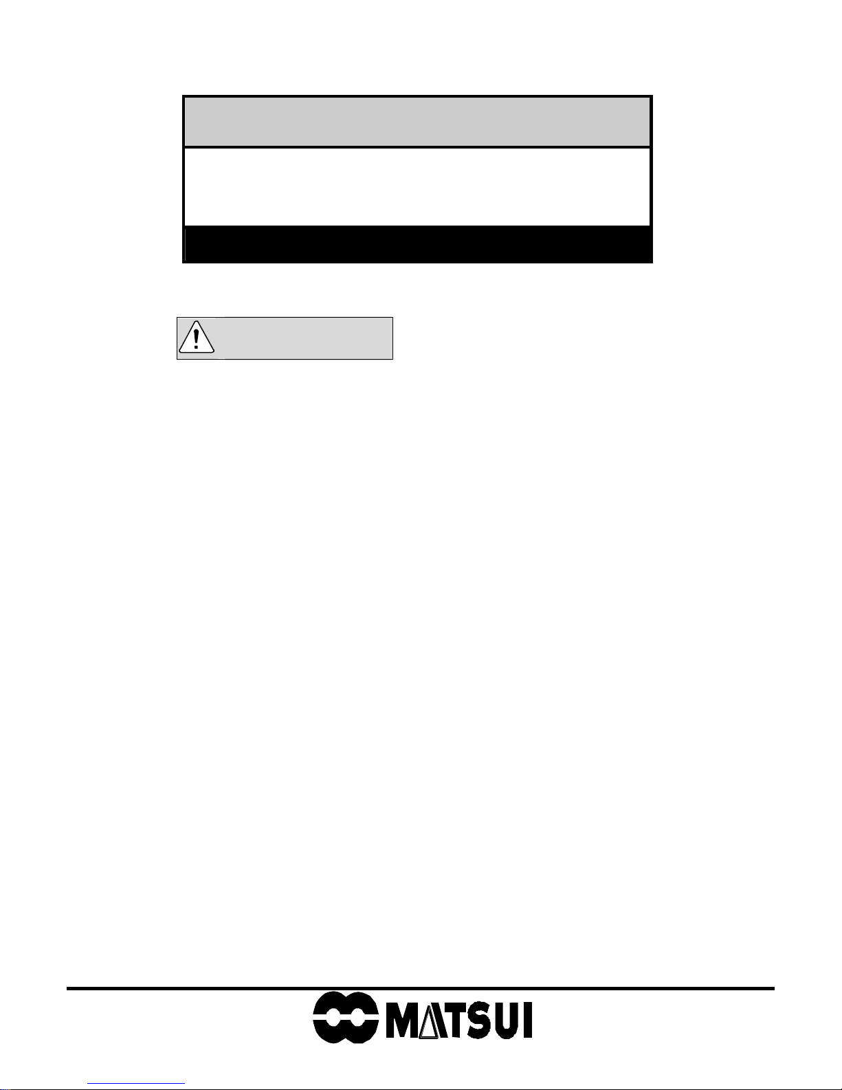
2. Flow diagrams (V type)
Flow diagram type 1
Suction hose
GL-1V Hose
Jet Clone type
limit control
Connector
PVC hose
Conveying hose
Signal cord
d
r
o
c
Suction nozzle
r
e
w
o
P
Suction unit
Flow diagram type 2
Jet Clone type
limit control
Chapter 1 Configuration of Equipment
2-way valves are shown in the following diagrams, however, in actuality,
3-6-directional valves can additionally be installed.
Flow diagram type 4
Jet Clone type
cylinder control
Connector
Suction unit
Flow diagram type 5
Suction hopper type
SD control
Connector
Suction unit
Flow diagram type 3
Suction hoppertype
E2K control
Connector
Connector
Suction unit
Suction unit
[WO-4841;JL4-V・VC-3~6-2]
- 2 -
Page 7
Flow diagrams (VC type)
Flow diagram type 6
GL-1V Hose
Jet Clone type
limit control
Connector
PVC hose
Conveying hose
Signal cord
d
Suction nozzle
Flow diagram type 7
r
o
c
r
e
w
o
P
Chapter 1 Configuration of Equipment
2-way valves are shown in the following diagrams, however, in actuality,
the valve is additionally installed in 3 to 6 directions, similarly.
Flow diagram type 9
Jet Clone type
cylinder control
Connector
Suction unit
Flow diagram type 10
Jet Clone type
limit control
Connector
Power cord
Flow diagram type 8
Suction unit
E2K control
Connector
Suction hopper type
SD control
Connector
Suction unit
Suction unit
[WO-4841;JL4-V・VC-3~6-3]
- 3 -
Page 8
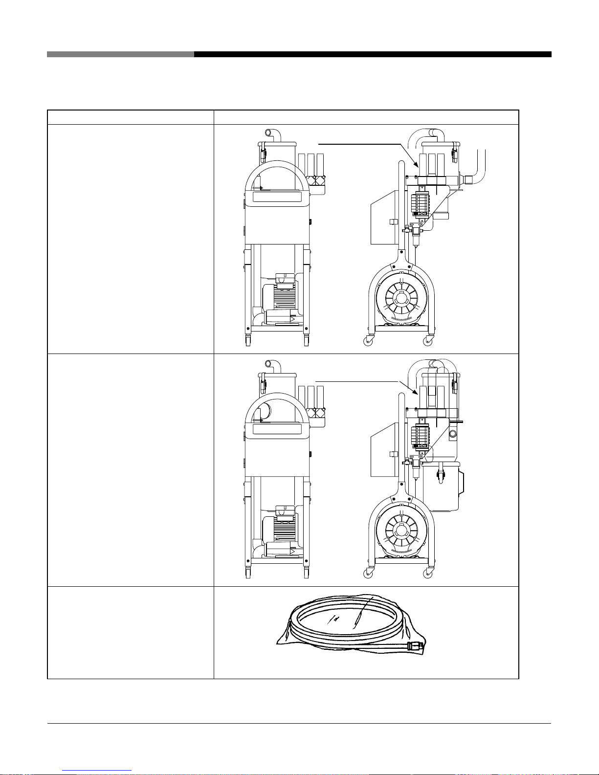
3. Packing list
Please confirm that all purchased devices are included.
Component Name Style of Packing
●Vacuum unit
JL4-(4,5,6)V-3~6 type
Chapter 1 Configuration of Equipment
3~6 way selector valve
●Vacuum unit
JL4-(4,5,6)VC-3~6 type
●Nylon hose
Aperture φ6, Length 5m
(Standard)
With one touch joint (1 pc.)
※1/4B equivalent product should be
used for coupler connection.
3~6 way selector valve
* The hose is contained in shrink wrap.
[WO-4841;JL4-V・VC-3~6-4]
- 4 -
Page 9
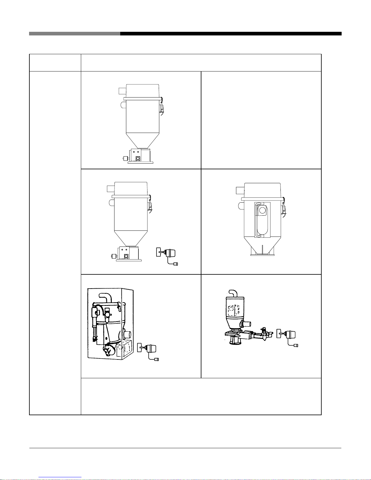
Component
Name
Collection hopper
● Jet Clone type limit control
● Jet Clone type level switch control
Style of Packing
●
Chapter 1 Configuration of Equipment
Suction hopper type E2K control
*
● Jet Clone type cylinder control
This unit is supplied with an injection
molding machine match base or chute.
● Suction hopper type ASD control
This unit is contained in a corrugated
*
cardboard case.
<NOTES> The elbow is contained for the Jet Clone type cylinder control and Vacuum
hopper type ASD control. The conditions are as follows.
1. For collection hoppers with an SUS lid, the elbow is attached to the lid.
2. For collection hoppers with an aluminum lid, the elbow is contained in
the corrugated cardboard case or the hopper in the collection hopper.
[WO-4841;JL4-V・VC-3~6-5]
- 5 -
Page 10
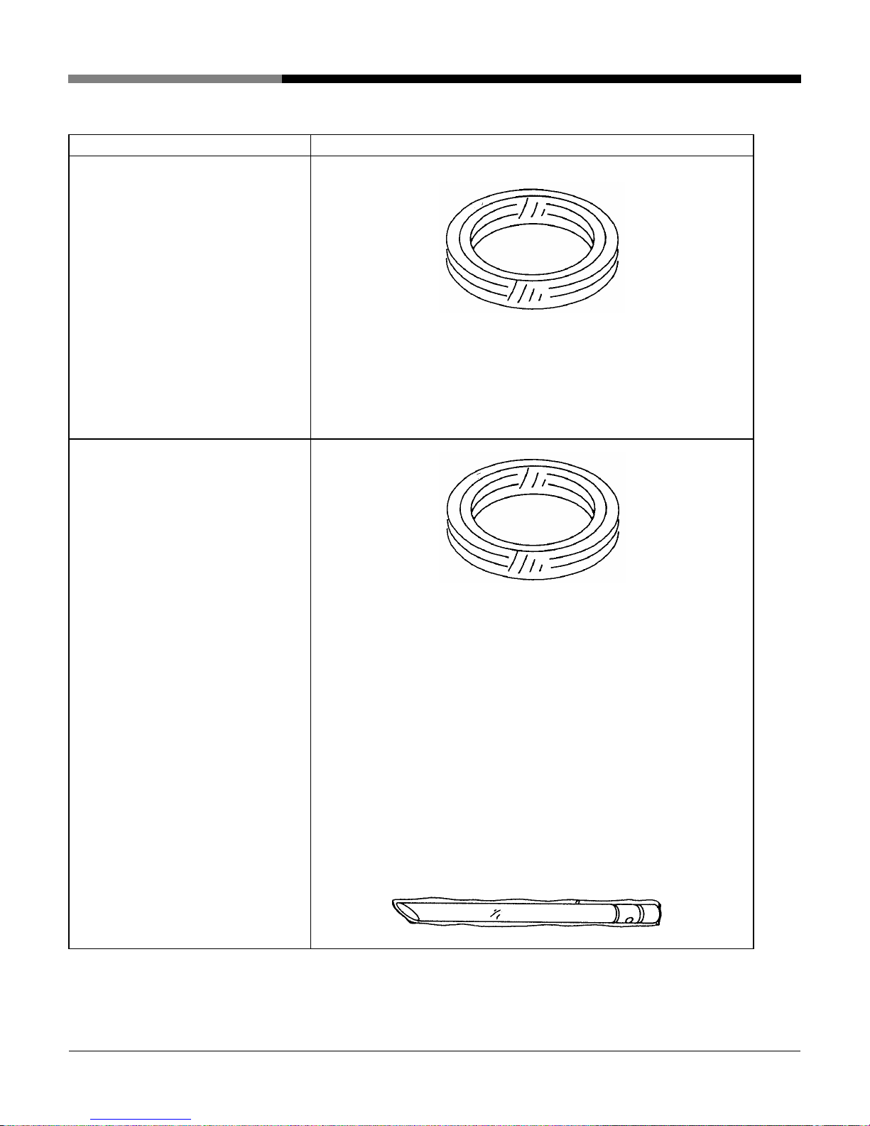
JL4-4V(VC)
JL4-5V(VC)
● Conveying hose (φ38 PVC hose)
JL4-4V(VC): Length 15 ft.
JL4-5V(VC): Length 15 ft.
● Vacuum hose (φ38 GTG hose)
Length 15 ft.
● Hose band (One set is 4 pcs.)
● Suction nozzle (φ38)
JL4-6V(VC)
Chapter 1 Configuration of Equipment
Style of Packing
Material & Vacuum hoses are wound with shrink wrap.
● Material hose (φ50 PVC hose)
Length 15 ft.
● Vacuum hose (φ65 GTG hose)
Length 15 ft.
(One set including 2 pcs.)
● Hose band (One set including 4
pcs.)
● Suction nozzle (φ50)
Material & Vacuum hoses are wound with shrink wrap.
*
The suction nozzle is wrapped in shrink wrap.
[WO-4841;JL4-V・VC-3~6-6]
- 6 -
Page 11

Chapter 2 For Safe Operation
This chapter contains instructions for operation, maintenance, and repair to operate
this equipment properly and safely. Also, this chapter explains the labels and
meaning of each indication on the product.
Indications for safety described in this manual should be observed when
operating or inspecting this product.
We shall not be responsible for any injury or accidents caused by failure to
observe these indications and we make no warranty against such injury or
accidents.
WARNING
1. Label and meaning of each indication
This instruction manual uses different indications depending on the extent of
danger as follows:
Label Meaning
WARNING
DANGER
This indication is used when failure to observe this may cause
user death. Instructions with this indication explain how to
prevent it.
This indication is used when failure to observe this may cause
users to be seriously injured. Instructions with this indication
explain how to prevent the injury.
CAUTION
NOTE
*
[WO-4841;JL4-V・VC-3~6-7]
This indication is used when failure to observe this may cause
users to be injured slightly or products to be damaged.
Instructions with this indication explain how to prevent them.
This indication is used when special care must be taken in
operation procedure or descriptions, and when the information
should be emphasized.
This mark is used when special care must be taken in handling.
This mark is used when exceptional conditions or cautions are
described in Tables and Figures.
- 7 -
Page 12

2. Items to be observed for safety
To operate this product safely, general instructions which should be
observed are described below.
Chapter 2 For Safe Operation
WARNING
1) Using environment
・ This equipment should be used indoors only.
・ This equipment should be used at ambient temperatures from 32°F / 0°C
to 104°F / 40°C and an ambient humidity of 25-85%.
2) Knowledge of electricity
Inspection or replacement by persons without sufficient knowledge of
electricity may cause defects or danger. Therefore, inspection and
replacement should be performed by a person at your company who has
sufficient knowledge about electricity.
3) Prohibition against operation in gases
Do not operate this equipment in flammable or explosive gases or vapors.
Operating this equipment in such an environment is very dangerous.
4) Prohibition against Modifications
This equipment must not be modified or altered by users without
obtaining our approval. We shall not be responsible for any accidents
caused by modifications or alterations.
5) Inspection
6) Maintenance
Before maintenance and inspection, be sure to stop operation and turn
“OFF” the power of the primary power supply of your equipment and
power switch of the control panel.
Also stop the compressed air fed to the air kit, press the drain valve of the
filter regulator to release residual pressure in air pipe.
Inspection and replacement of parts must be performed by persons who
have sufficient knowledge about this product. Inspection and replacement
by persons without sufficient knowledge about the product may cause
defects or danger.
When maintenance or repair advice is necessary, contact the Matsui
service department, or your local sales representative.
[WO-4841;JL4-V・VC-3~6-8]
- 8 -
Page 13

Chapter 2 For Safe Operation
1) Disposal of the product and parts
This product and parts are handled as industrial waste and are regulated
by the “Waste Disposal and Public Cleaning Law.” Request subcontractors
who have received an “industrial waste collecting and transporting
permit” or “industrial waste disposal permit” to dispose of products and
parts. For details, contact your local or state environmental development
office.
2) Power supply
This equipment should be operated with a line voltage and frequency
conforming to local or state specifications.
* Be sure to connect the ground wire (to earth).
3) Use of the equipment
This product is a conveying unit for resin pellets. This is not suitable for
other materials, and conveying materials other than resin pellets may
cause defects.
We make no warranty against any problems caused by using materials
other than resin pellets.
CAUTION
3. Labels
1) Handling of label
1) Wiping
Labels are pasted where special care must be taken to prevent danger.
Warnings or cautions must be thoroughly understood before starting an
operation.
● Keep the labels legible until scrapping the equipment.
● When a label becomes dirty, wipe it with a soft cloth soaked in warm
water and well wrung out.
NOTE
Do not wipe the equipment using petroleum solvents. Cleaning with
benzene, thinner, and polishing powder will scratch the surface.
When equipment is blemished badly, wipe it with a soft cloth soaked in
warm water.
[WO-4841;JL4-V・VC-3~6-9]
- 9 -
Page 14
Chapter 3 Installation
This Chapter describes installation work of the product for each piece of
equipment according to the procedure.
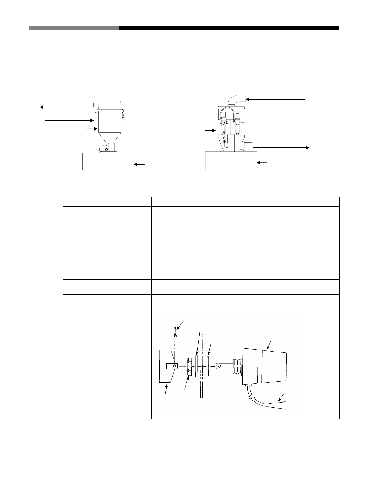
1. Mounting collection hopper
1) Jet Clone type limit, level, cylinder control
Material port hose
Vacuum port hose
Material port
hose
Jet Clone
Hopper
Jet Clone- limit switch control Jet Clone- pneumatic cylinder control (not common)
Jet Clone
Step Task Description
Drilling mounting holes Drill holes in the hopper to be mounted so that they match the
1
mounting holes in the Jet Clone.
* It is recommended to tap the hopper holes so that the collection
hopper can be secured with bolts alone. When the holes are not
tapped, the collection hopper should be secured with bolts and
nuts. In this case, an adequate measure should be taken to
prevent the bolts and nuts from falling into the hopper if they
loosen and fall off.
Mounting Jet Clone
2
Mounting level switch
3
* Only when the
collection hopper is
controlled by the
level switch
(not common)
Mount the Jet Clone on the hopper on which mounting holes are
drilled.
Drill holes at the specified positions in the hopper on which the
suction hopper is mounted, and install the level switch.
Pneumatic
Split pin
Flat washer
Packing
Vacuum port hose
Hopper
Level switch main body
[WO-4841;JL4-V・VC-3~6-10]
Nut
Connector
Blade
- 10 -
Page 15

The hopper on which the Jet Clone is mounted should be sized so that the damper of the Jet Clone
○
does not contact the inner wall of the hopper.
○ Install the Jet Clone horizontally. Otherwise, it may not accurately detect the hopper is full of
material.
○ The damper of the Jet Clone has been adjusted at the factory, therefore do not adjust, or knock it.
Otherwise, it may not accurately detect the hopper is full of material.
NOTE
Chapter 3 Installation
[WO-4841;JL4-V・VC-3~6-11]
- 11 -
Page 16
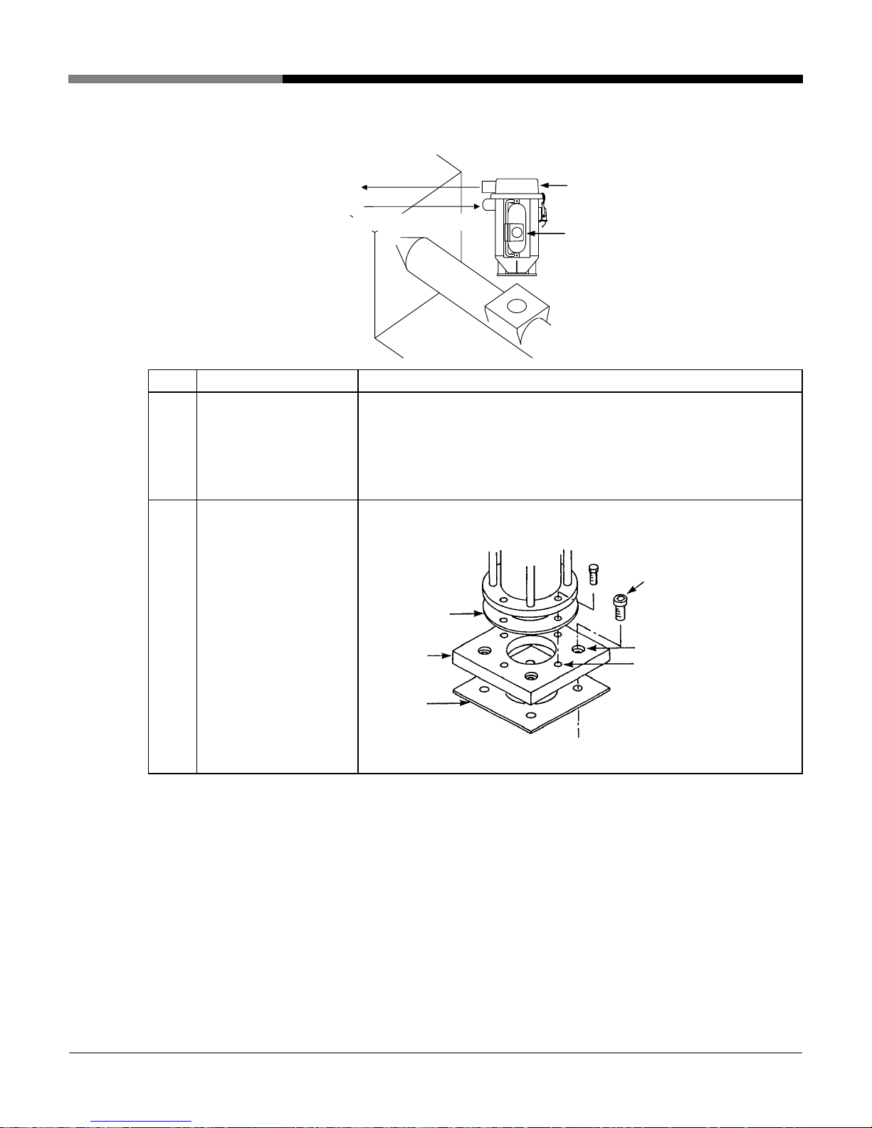
2) Vacuum hopper type- E2K control
Step Task Description
Mounting the base Attach the base to the molding machine.
1
2
Vacuum hopper
mounting
Chapter 3 Installation
Inlet Vac. hose
Material port hose
Molding
machine
Vacuum hopper
Proximity switch (E2K)
(Fix with hexagon socket head cap screws.)
* Be sure to install a gasket between the hopper base and the
molding machine mounting plate.
Mount the vacuum hopper flange (sight glass section) on the base.
Use hexagon socket head
socket screws.
Packing
Matching
base
Countersunk hole (for
molding machine
mounting)
Tap hole (for suction hopper
mounting)
Packing
[WO-4841;JL4-V・VC-3~6-12]
- 12 -
Page 17
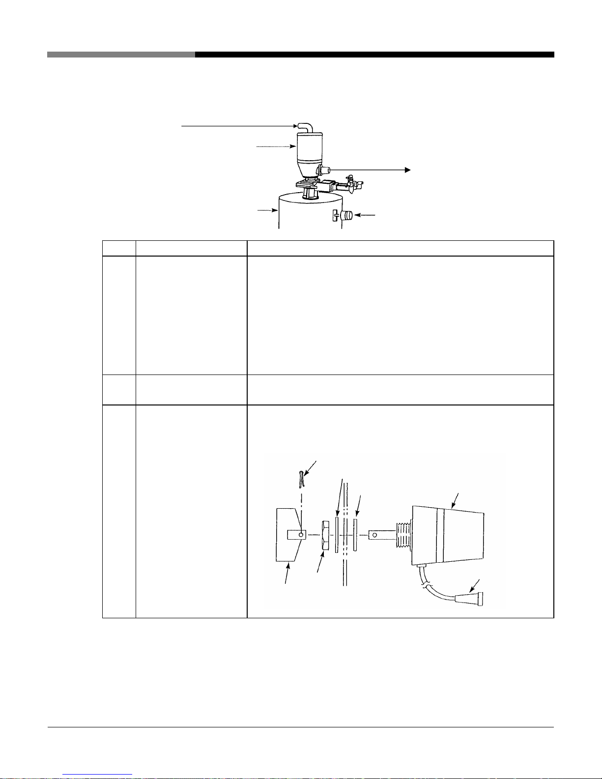
3) Vacuum hopper type ASD control (not common)
Material port hose
Vacuum hopper
Step
Drilling the mounting
1
Task Description
holes
Mounting suction hopper Mount the suction hopper to the hopper on which the mounting holes
2
Hopper
Drill holes in the hopper to be mounted so that they match the
mounting holes in the Jet Clone.
* It is recommended to tap the hopper holes so that the collection
hopper can be secured with bolts alone. When the holes are not
tapped, the collection hopper should be secured with bolts and
nuts. In this case, an adequate measure should be taken to
prevent the bolts and nuts from falling into the hopper if they
loosen and fall off.
are drilled.
Vacuum port hose
Level switch
Chapter 3 Installation
3 Mounting level switch Drill holes at the specified positions in the hopper on which the
suction hopper is mounted, and install the level switch.
Split pin
Flat washer
Packing
Level switch (main body)
Blade
Nut
Connector
[WO-4841;JL4-V・VC-3~6-13]
- 13 -
Page 18
2. Installation
Install the equipment as shown in 2. Flow diagrams in Chapter 1.
Step Task Description
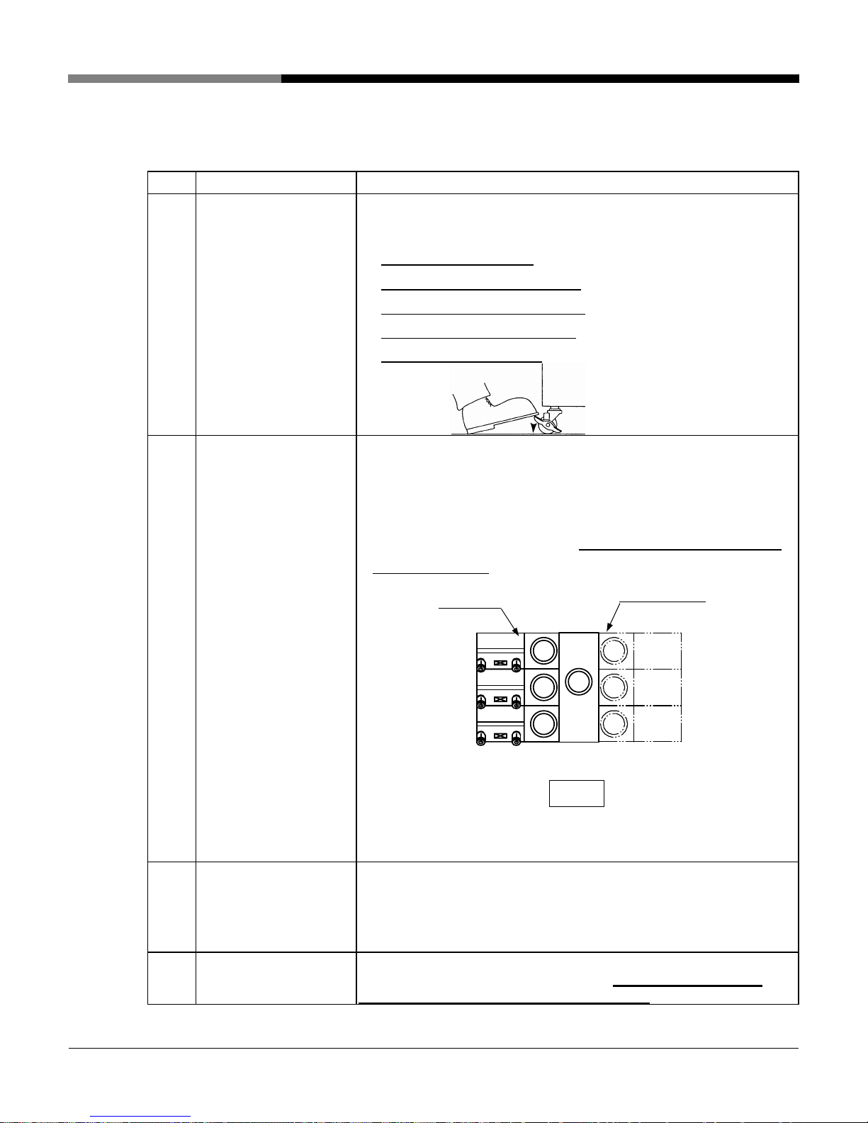
1
Installing the Loader Install the loader near each collection hopper (within the reach of the
2
Mounting the vacuum
hoses (Grey GTG Hose)
Chapter 3 Installation
5m-long air suction hose) in the vicinity of respective collectors.
* When the installing location is
determined, be sure to apply the caster
brakes (4 locations) to secure. As shown
in the diagram, the brake is applied by
stepping down on the ON side.
Connect the vacuum hoses to the suction ports of each collection
hopper and the 3 ~ 6 way selector valve of the loader.
* Be sure to secure with a hose clamp.
Connecting the material
3
hose (White PVC Hose)
Connecting the signal
4
cords
* A direction label (No1.~ No.6) is attached to respective hose
openings on the selector valves. Please make sure to connect to
each proper valve.
For 3 way
For 4 – 6 way
(3 ~ 6 way selector valve viewed from above)
NOTE
Securely tighten the hose clamps to avoid leaks at the intake ports of
the material & vacuum hoses.
Connect the material hose to the material port of each collection
hopper.
Install the suction nozzle to the end (conveying source side) of the
conveying hose.
* Firmly secure with a hose clamp.
Connect the signal cords (with connector) of the loader to the signal
cord, or socket, of the collection hopper. Make sure each cable
matches the corresponding hose direction!
[WO-4841;JL4-V・VC-3~6-14]
- 14 -
Page 19
Step Task Description
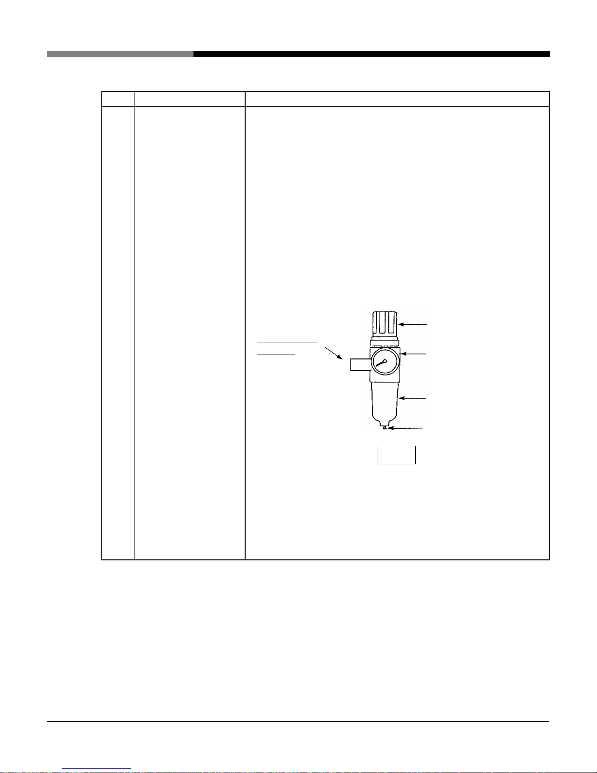
5
Supplying compressed
air to the (3 ~ 6 way)
selector valve
Chapter 3 Installation
Connect an air hose of compressed air source from your facility
to the air supply valve (1/4”) of the 3~6 way valve.
Fully open the valve of the air kit to supply dry compressed air
of 0.5 MPa or higher from the compressed air source.
↓
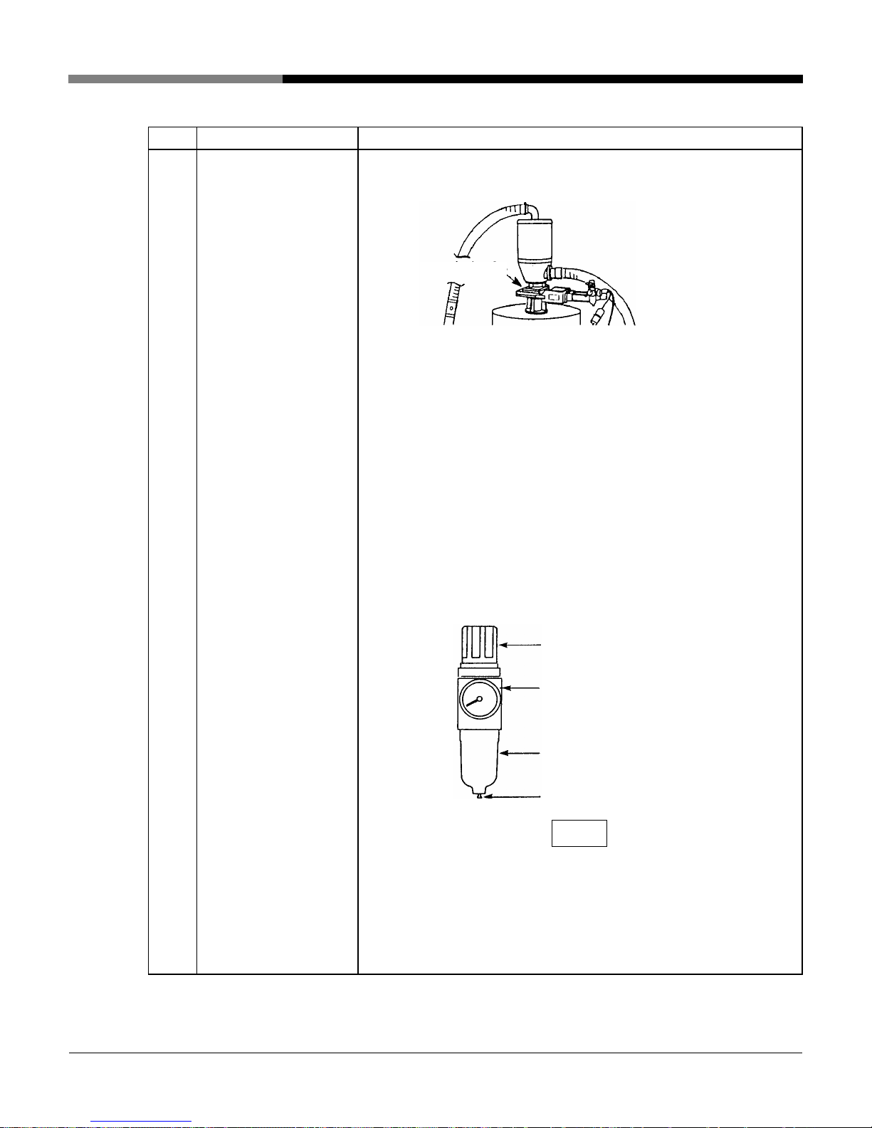
Set the filter regulator outlet pressure of the air kit within a range of 0.4 to 0.5 MPa.
① Pull up the filter regulator adjustment knob to unlock it.
② Adjust the indication of the pressure gauge to 0.4 to 0.5
MPa by turning the adjustment knob clockwise or
counterclockwise. Turning the knob clockwise causes the
indicated value to rise, and vice versa.
③ After setting the pressure, push down the adjustment
knob to lock it.
Adjustment
knob
Supply valve
(1/4”)
(Your valve may
Pressure
gauge
differ).
Bowl
Drain valve
NOTE
○ Set the pressure to
0.5 MPa or higher for dry compressed air
from a compressed air source.
Use an air dryer or air filter to obtain clean, dry compressed
air. Periodically drain to prevent freezing of the drain water,
especially in cold climates.
[WO-4841;JL4-V・VC-3~6-15]
- 15 -
Page 20
Step
Supplying compressed
6
Task
air to collection hopper
air kit
* Only when the
collection hopper is Jet
Clone pneumatic
cylinder control type or
suction hopper type has
ASD control.
(not common)
Chapter 3 Installation
Description
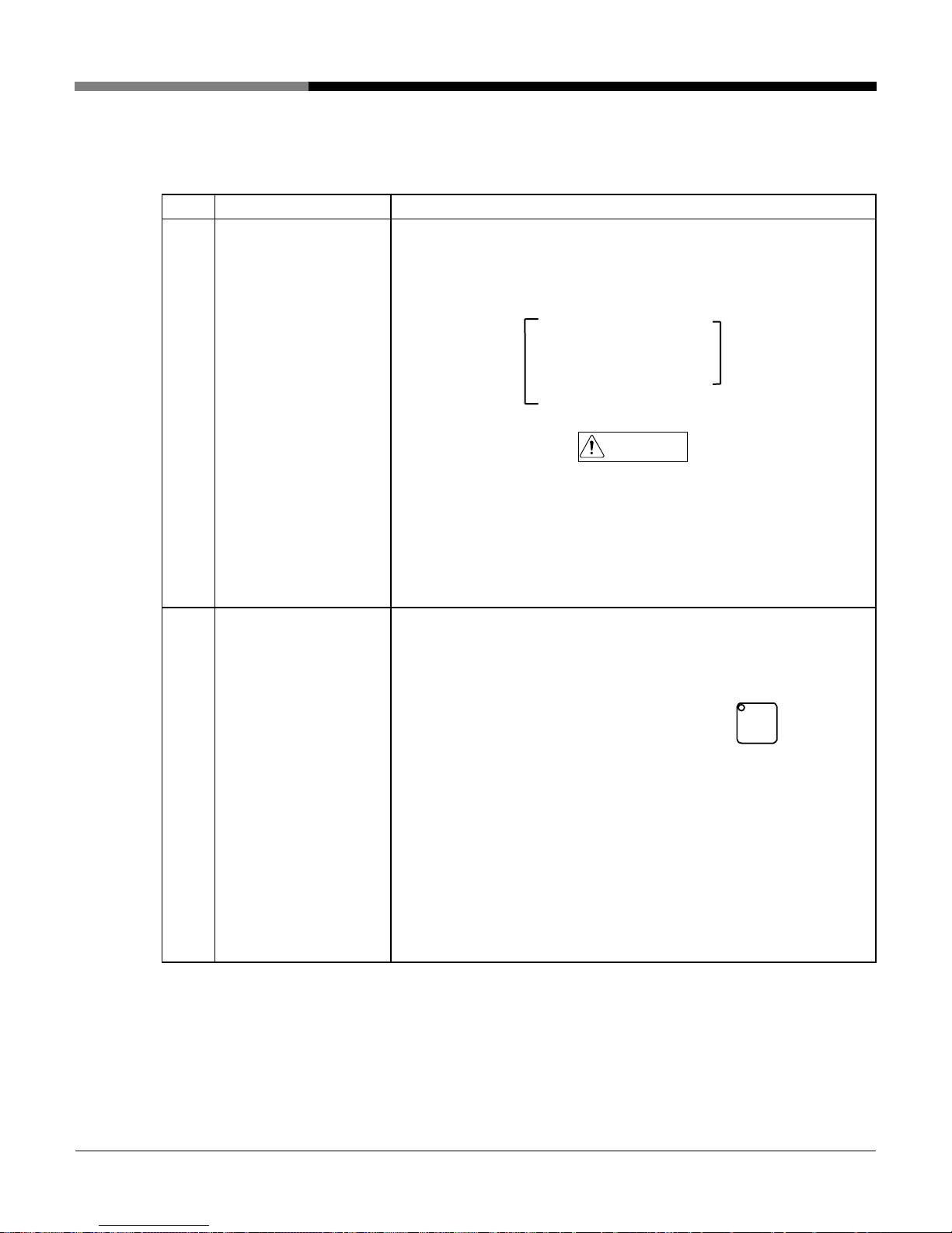
Connect an air hose for a compressed air source to the air supply
port valve of the automatic slide gate air kit from your existing source.
Fully open the valve of the air kit to supply dry compressed air of 0.5
MPa or higher from the compressed air source.
Set the filter regulator outlet pressure of the air kit within a range of
0.4 to 0.5 MPa.
AutoSlide gate
↓
↓
① Pull up the filter regulator adjustment knob to unlock it.
② Adjust the indication of the pressure gauge to 0.4 to 0.5 MPa
by turning the adjustment knob clockwise or counterclockwise.
Turning the knob clockwise causes the indicated value to rise,
and vice versa.
③ After setting the pressure, push down the adjustment knob to
lock it.
Adjustment knob
Pressure gauge
Bowl
Drain valve
NOTE
○ Secure pressure of 0.5 MPa or higher for dry compressed air from
the compressed air source.
Properly process with an air dryer or air filter to use clean dry
compressed air. Sufficiently drain to prevent freezing of drain
water especially in cold climates.
[WO-4841;JL4-V・VC-3~6-16]
- 16 -
Page 21
3. Power cord Information
WARNING! Only qualified personnel should attempt any electrical connections!
Step Task Description
1
Connecting / Checking
the power cord
2
Checking forward and
reverse phase
After checking that the power breaker in the control panel is OFF, check
the 15ft. long power cord to the primary power of your existing source.
R phase …Red
Power cord … S phase …White …For the primary
T phase …Black
E phase …Green …………For grounding
○ Before any power cord connection, be sure to set the power circuit
○ The power cord should be securely connected to the power source. A
○ Be sure to connect the ground.
Turn OFF the primary power of your existing source.
↓
CAUTION
breaker in the control panel to OFF.
loose power cord connection may cause abnormal equipment
operation, single-phase operation and heat generation, or danger.
Turn ON the primary power of your existing source.
↓
Turn on the power breaker in the control panel.
↓
Chapter 3 Installation
1
Press the operation panel No. 1 start/stop switch
blower for the suction unit starts after the predetermined time.
↓
Apply your hand to the blower exhaust port to check that air is
blowing out from the exhaust port. If so, the blower rotates in the
forward direction (forward phase). Connection of the power cord is
completed.
↓
Continued on the next page.
No.
and the
- 17 -
[WO-4841;JL4-V・VC-3~6-17]
Page 22
Step Task Description
3
Checking forward and
reverse phase
Chapter 3 Installation
↓
If no air is blowing out from the exhaust port, it means that the blower
rotates in the reverse direction (reverse phase). In this case, turn OFF
the primary power and reverse the R phase and T phase of the three
wires of the power cord.
↓
Again, turn ON the primary power and check that air is blowing out
from the exhaust port.
Exhaust port
[WO-4841;JL4-V・VC-3~6-18]
- 18 -
Page 23
Chapter 4 Preparations for Operation
This chapter describes checks before starting operation.
1. Check status of each component
Unit to be checked Check
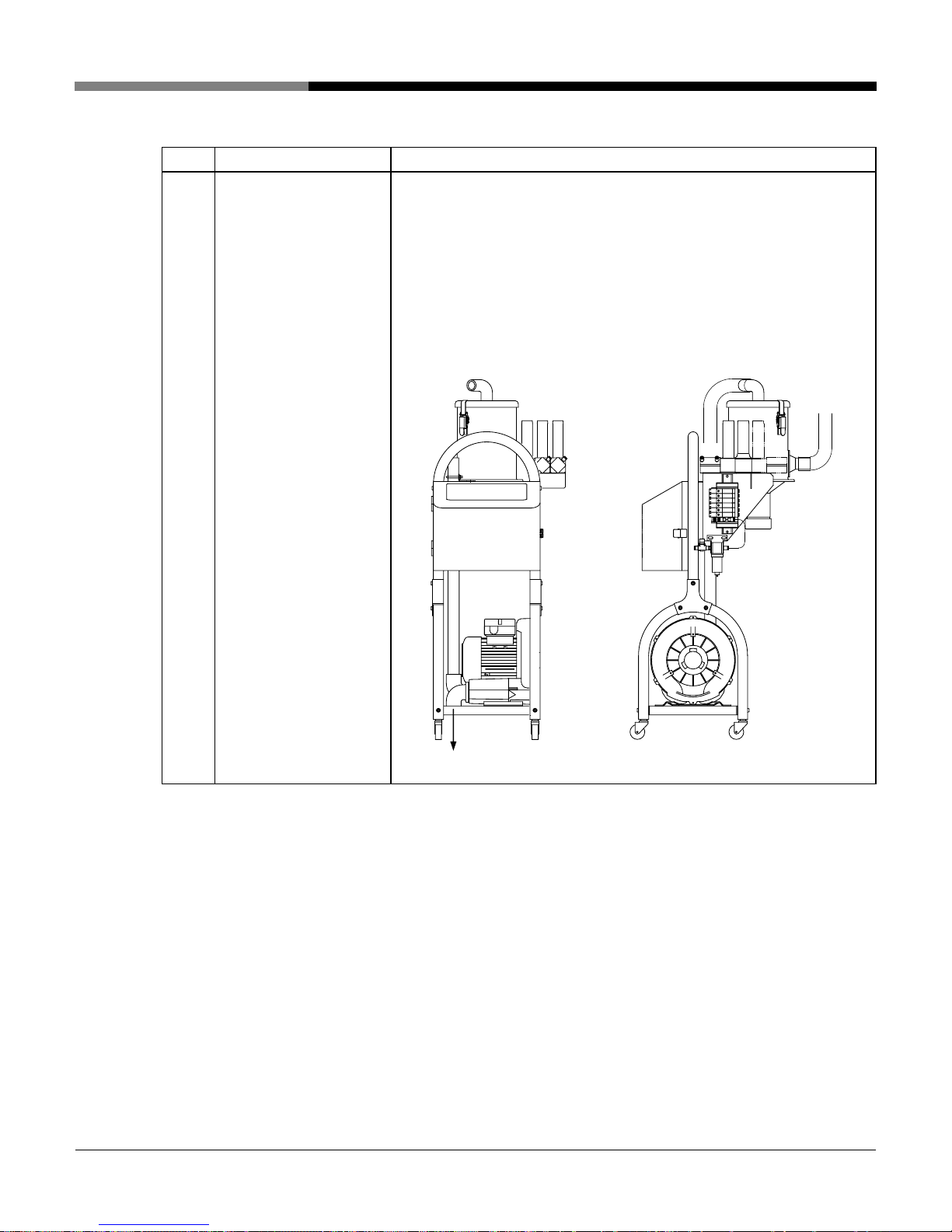
Filter case for suction unit Check that the cartridge and cap are set to the filter case.
Filter case
Filter case
Separator
Dust box for suction unit
* Only for VC type
Cap
V type VC type
Check that the dust box is installed on the lower part of the separator.
(Refer to the above diagram.)
Dust box
[WO-4841;JL4-V・VC-3~6-19]
- 19 –
Page 24

A
p
Unit to be checked Check
Each collection hopper
Chapter 4 Preparations for Operation
Check that no foreign matter intrudes inside, and further check that the
packing and metal mesh filter are properly set.
fter checking, firmly fix the lid of the collection hopper with the catch clips
(3 pieces).
Lid
Packing
Filter
Catch cli
[WO-4841;JL4-V・VC-3~6-20]
- 20 –
Page 25

2. Control panel description
・Discharging display/Engineering setting mode display (green)
・Conveying display/User setting mode display (green)
・Digital displayer (red)
PV value/Function
・Digital displayer (green)
SV value/Parameter
Chapter 4 Preparations for Operation
・Reset switch
Jet Loader
PV SV
Conveyance
/User Setting
Discharge
/Engineering Setting
Feed to
Run
Stop
Setting
・SV switch
・Down switch
/Function /Parameter
21
No.No.
3456
No. No. No. No.
SV
Reset
・ Confirmation
switch
・Up switch
・No. 1 start/stop
Switch/display (green)
~
・No. 6 start/stop
Switch/display (green)
[WO-4841;JL4-V・VC-3~6-21]
- 21 –
Page 26

Chapter 5 Operating Procedures
This Chapter describes starting, stopping and cleaning procedures according
to the steps.
1. Starting procedure
Step Operation Description Display
Turning on power Turn ON the power breaker in the control panel.
1
2
Starting operation Press a desired switch from the No. 1 start/stop
1
switch
No.
The equipment starts conveyance in response to
a request signal.
However, when the collection hopper is full, the
equipment does not start conveyance.
* For details on operation, refer to Chapter 6.
Operational Descriptions and Timing Chart.
No.
to the No. 6 start/stop switch
6
on the operation panel.
↓
↓
The display
corresponding to
operation of
1
No.
through
No.
6
is turned on during
start.
Conveying set time
(green) and conveying
time (red) appear on the
digital displayer during
conveyance.
Discharge set time
(green) and discharge
time (red) appear on the
digital displayer during
discharge.
[Adjusting the amount of secondary air suctioned by
the suction nozzle]
Put the suction nozzle into the material and adjust the
secondary air regulator to achieve smooth material
conveyance.
Secondary air regulator
NOTE
Throttling secondary air flow excessively may cause the hose to be clogged with material.
[WO-4841;JL4-V・VC-3~6-22]
- 22 –
Page 27

2. Stopping procedure
Step Operation Description Display
Chapter 5 Operating Procedures
1
Operation is continued for operation performance during cycle stop.
Stopping
operation
Press a desired switch from the No. 1 start/stop
1
No.
switch
No.
6
on the operation panel.
The equipment stops operation.
If operation is stopped during conveyance
operation, the device is stopped after
conveyance operation. (Cycle stop)
to the No. 6 start/stop switches
↓
NOTE
The display
corresponding to
operation of
1
No.
through
No.
6
is turned on during
start.
[WO-4841;JL4-V・VC-3~6-23]
- 23 –
Page 28

3. Cleaning procedure
This section describes the procedure for cleaning the conveying hoses and
collection hoppers after stopping equipment operation.
Step Operation Description Display
1 Preparation work Remove the suction nozzle at the end of the
conveying hose from the material supply
section.
2 Starting operation Perform the operation to start conveyance to the
collection hopper. (Refer to the previous page.)
3
Cleaning inside
of conveying
hose
Play up the suction nozzle opening with your
hand at intervals of several seconds during
conveyance to completely feed the material
remaining in the conveying hose to the
collection hopper.
Chapter 5 Operating Procedures
(Refer to the previous
page.)
Stopping
4
operation
Cleaning inside
5
of collection
hopper
Perform the stopping operation to stop the
conveyance to the collection hopper. (Refer to
the previous page.)
Remove the lid of the collection hopper to clean
the inside.
(Refer to the previous
page.)
[WO-4841;JL4-V・VC-3~6-24]
- 24 –
Page 29

Chapter 6 Operational Descriptions and Timing Charts
r
This Chapter describes the operation for the collection hopper.
1. Jet Clone type limit or level switch control collection hopper
1) Description of operations
Set the control panel power circuit breaker to ON.
↓
When the equipment starts conveyance by the start of
operation, the blower starts rotating in response to the
request signal from the limit switch. At the same time, the
collection hopper gate closes.
↓
Material is conveyed to the collection hopper of the period
of time set by the conveyance timer.
↓
Gate operations
ダンパー動作説明図
(1) Normal condition
(1)自然状態
Limit switch
リミットスイッチ
Cam
カム ダンパー
Dampe
When the conveyance timer has run out, the blower stops.
As the suction pressure decreases the collection hopper
gate opens to discharge material into the lower receiver
hopper for the period of time set on the discharge timer.
↓
The above operations are repeated.
In a case where respective request signals from multiple
conveyance directions are simultaneously sent, the
material is conveyed in the order of No. 1 → No. 2 → No. n
→ No.2, alternatively.
When the receiver hopper has become full, the collection
hopper limit switch (in the case of limit control) or the
receiver hopper level switch (in the case of level switch
control) senses the condition to stop conveyance.
When a request signal is sensed again, conveyance is
started.
(2) Closed
(during conveyance)
(3) Full condition
condition
(2)閉(輸送中)状態
(Limit switch actuation
(3)材料満杯状態
Æ Material conveyance stop)
(リミットスイッチ作動
→輸送停止)
材料
Material
[WO-4841;JL4-V・VC-3~6-25]
- 25 -
Page 30

2) Timing chart
The following is the time chart for No.1 and No. 2 directions, however, operation for No. 3 direction or
more is similarly carried out.
Start/stop switch
1
No.
No.
2
Request
No. 1 Request signal
Request
No. 2 Request signal
No. 1 Discharge timer
ON
Chapter 6 Operational Descriptions and Time Charts
Full
Request
Full
Operating
UP
Operating
No. 1 Discharge timer
Ring blower
No. 1 collection hopper gate
No. 2 collection hopper gate
No. 1 Conveyance timer
No. 2 Conveyance timer
3~6 way selector valve
UP
Start
Stop
Stop
Start
Stop
Open
Close
Close
Open
Close
Close
Operating
UP
Operating
UP
No. 1direction
No. 2 direction
Close Close
Start
Open
Operating
No. 1direction
[WO-4841;JL4-V・VC-3~6-26]
- 26 -
Page 31

Chapter 6 Operational Descriptions and Time Charts
2. Suction hopper type E2K control collection hopper
1) Description of operations
Set the control panel power circuit breaker to ON.
↓
When the equipment starts conveyance by the start of operation, the blower starts rotating in response
to the request signal from the E2K.
↓
Material is conveyed to the collection hopper for the period of time set by the conveyance timer.
↓
When the conveyance timer has run out, the blower stops.
↓
The above operations are repeated.
In a case where respective request signals from multiple conveyance directions are simultaneously
sent, the material is conveyed in the order of No. 1 → No. 2 → No. n → No.2, alternatively.
When the collection hopper has become full, the E2K installed on the collection hopper senses the
conditions to stop conveyance.
When a request signal is sensed again, conveyance is started.
[WO-4841;JL4-V・VC-3~6-27]
- 27 -
Page 32

2) Timing chart
The following is the time chart for No.1 and No.2 directions, however, operation for No.3 direction or
more is similarly carried out.
Start/stop switch
1
No.
No.1 Request signal
No.2 Request signal
No.1 Discharge timer
No.2 Discharge timer
No.
2
ON
Request
Request
Chapter 6 Operational Descriptions and Time Charts
Full
Request
Full
Operating
UP
Operating
UP
Ring blower
No.1 Conveyance timer
No.2 Conveyance timer
3 - 6-way selector valve
Start
Stop
Operating
Stop
Start
Stop
Operating
UP
UP
No.1 direction
Close Close
No.2 direction
Start
Operating
No.1 direction
[WO-4841;JL4-V・VC-3~6-28]
- 28 -
Page 33

Chapter 6 Operational Descriptions and Timing Charts
3. Jet Clone cylinder control or suction hopper type SD control
collection hopper
1) Description of operation
Set the control panel power circuit breaker to ON.
↓
When the equipment starts conveyance by the start of operation, the discharge timer starts and after
the lapse of the preset time, the blower starts rotating in response to the request signal from the level
switch.
↓
Material is conveyed to the collection hopper for the period of time set by the conveyance timer.
↓
When the conveyance timer has run out, the blower stops. The collection hopper gate opens to
discharge material for the period of time set on the discharge timer.
↓
The above operations are repeated.
In a case where respective request signals from multiple conveyance directions are simultaneously
sent, the material is conveyed in the order of No. 1 → No. 2 → No. n → No. 2, alternatively.
When the receiver hopper has become full, the level switch installed on the receiver hopper senses the
conditions to stop conveyance.
When a request signal is sensed again, conveyance is started.
[WO-4841;JL4-V・VC-3~6-29]
- 29 -
Page 34

2) Timing chart
The following is the time chart for No.1 and No.2 directions, however, operation for No.3 direction or
more is similarly carried out.
Start/stop switch
1
No.
No.1 Request signal
No.2 Request signal
No.1 Discharge timer
No.
2
ON
Request
Request
Operating
UP
Chapter 6 Operational Descriptions and Timing Charts
Full
Request
Full
Operating
UP
No.2 Discharge timer
Ring blower
No. 1 collection hopper gate
No. 2 collection hopper gate
No.1 Conveyance timer
No.2 Conveyance timer
3~6-way selector valve
Operating
Start
Stop
Open
Close
Close
Close
Operating
Open
Close
Open
UP
No.1 direction
Close Close
UP
Start
Close
Operating
No.2 direction
Operating
UP
Start
Stop
Open
Close
Operating
UP
No.1 direction
[WO-4841;JL4-V・VC-3~6-30]
- 30 -
Page 35

Chapter 7 Respective Parameter Setup
This chapter describes respective parameter setup carried out on the operation
panel.
Respective parameter setup is classified into user setting mode and engineering
setting mode.
NOTE
The parameters of the engineering setting mode have been set according to the
specification at shipment or at installation. In general, there is no need to change
the setting. When changing the setting, sufficiently understand the functions.
When in doubt, contact our responsible personnel.
1. Setting guide
User setting mode
No. Code Setting item
1 Fd1 No. 1
Conveyance
timer
2 Fd2 No.2
Conveyance
timer
3 Fd3 No.3
Conveyance
timer
4 Fd4 No.4
Conveyance
timer
5 Fd5 No.5
Conveyance
timer
6 Fd6 No.6
Conveyance
timer
The timer should be set for No.1 conveyance
time.
The time for conveyance varies with the
conveying distance, the type of material, and
the type of collection hopper.
The conveyance timer should be set so that
conveyance ends before the collection hopper
becomes full of material.
The timer should be set for No.2 conveyance
time. Hereinafter, same as above.
The timer should be set for No.3 conveyance
time. Hereinafter, same as above.
The timer should be set for No.4 conveyance
time. Hereinafter, same as above.
The timer should be set for No.5 conveyance
time. Hereinafter, same as above.
The timer should be set for No.6 conveyance
time. Hereinafter, same as above.
Function
Setting
range
0 - 999 sec 5 sec
Same as
above
Same as
above
Same as
above
Same as
above
Same as
above
Initial
value
Same
as
above
Same
as
above
Same
as
above
Same
as
above
Same
as
above
[WO-4841;JL4-V・VC-3~6-31]
- 31 -
Page 36

No. Code Setting item
7 dC1
Conveyance
8 dC2
Conveyance
9 dC3
Conveyance
10 dC4
Conveyance
11 dC5
Conveyance
12 dC6
Conveyance
13 dUC Dust cleaning
14 dUP Dust cleaning
No. 1
timer
No.2
timer
No.3
timer
No.4
timer
No.5
timer
No.6
timer
counter
count
Chapter 7 Respective Parameter Setup
Function
The timer should be set for No.1 conveyance
time.
The time for conveyance varies with the
conveying distance, the type of material, and
the type of collection hopper.
The conveyance timer should be set so that
conveyance ends before the collection hopper
becomes full of material.
The timer should be set for No.2 conveyance
time.
The timer should be set for No.3 conveyance
time.
The timer should be set for No.4 conveyance
time.
The timer should be set for No.5 conveyance
time.
The timer should be set for No.6 conveyance
time.
The counter should be set for conveyance
times to inform filter cleaning interval.
If this counter is set to OFF, this does not
function. When the conveyance times reach
the set value, E15 appears on the digital
displayer on the operation panel, informing of
the cleaning interval.
The set times vary with properties of the
conveying material and operating status.
This displays the count number of the dust
cleaning counter.
When this is set to 0, the count number is
reset.
Setting
range
0 - 999 sec 20
Same as
above
Same as
above
Same as
above
Same as
above
Same as
above
oFF,
1 – 999
times
0 – 999
times
Initial
value
sec
Same
as
above
Same
as
above
Same
as
above
Same
as
above
Same
as
above
oFF
0
[WO-4841;JL4-V・VC-3~6-32]
- 32 -
Page 37

No. Code Setting item
1 L1d No. 1
Request signal
delay timer
2 L2d No.2 Request
signal delay
3 L3d No.3 Request
signal delay
4 L4d No.4 Request
signal delay
5 L5d No.5 Request
signal delay
6 L6d No.6 Request
signal delay
7 1Ed No. 1
Conveyance
error timer
8 2Ed No. 2
Conveyance
error timer
9 3Ed No. 3
Conveyance
error timer
10 4Ed No. 4
Conveyance
error timer
11 5Ed No. 5
Conveyance
error timer
12 6Ed No. 6
Conveyance
error timer
13 1rL No. 1
Request signal
input select
timer
timer
timer
timer
timer
Chapter 7 Respective Parameter Setup
Engineering setting mode
Function
The timer should be set for the time to judge
No.1 request signal.
The timer should be set so as to disregard a
false request signal in short time due to flowing
of material.
The timer should be set for the time to judge
No.2 request signal. Hereinafter same as
above.
The timer should be set for the time to judge
No.3 request signal. Hereinafter same as
above.
The timer should be set for the time to judge
No.4 request signal. Hereinafter same as
above.
The timer should be set for the time to judge
No.5 request signal. Hereinafter same as
above.
The timer should be set for the time to judge
No.6 request signal. Hereinafter same as
above.
The timer should be set for level switch
request status monitoring time during No. 1
conveying operation.
The timer should be set for level switch
request status monitoring time during No. 2
conveying operation.
The timer should be set for level switch
request status monitoring time during No. 3
conveying operation.
The timer should be set for level switch
request status monitoring time during No. 4
conveying operation.
The timer should be set for level switch
request status monitoring time during No. 5
conveying operation.
The timer should be set for level switch
request status monitoring time during No. 6
conveying operation.
This should be set for the type of No.1 request
signal.
no: State where input circuit is open should be
a request signal.
nC: State where input circuit is close should be
a request signal.
Setting
range
0 - 99 sec
Same as
above
Same as
above
Same as
above
Same as
above
Same as
above
oFF,
1 - 999 sec
oFF,
1 - 999 sec
oFF,
1 - 999 sec
oFF,
1 - 999 sec
oFF,
1 - 999 sec
oFF,
1~999
sec
nC/no
Initial
value
5 sec
Same
as
above
Same
as
above
Same
as
above
Same
as
above
Same
as
above
oFF
oFF
oFF
oFF
oFF
oFF
no
[WO-4841;JL4-V・VC-3~6-33]
- 33 -
Page 38

No. Code Setting item
14 2rL No. 2
Request signal
input select
15 3rL No.3 Request
signal input
16 4rL No.4 Request
signal input
17 5rL No.5 Request
signal input
18 6rL No.6 Request
signal input
19 bt1 No. 1
Batch gate timer
20 bt2 No.2 Batch gate
21 bt3 No.3 Batch gate
22 bt4 No.4 Batch gate
23 bt5 No.5 Batch gate
24 bt6 No.6 Batch gate
select
select
select
select
timer
timer
timer
timer
timer
Chapter 7 Respective Parameter Setup
Function
This should be set for the type of No. 2
request signal.
Hereinafter same as above.
This should be set for the type of No. 3
request signal.
Hereinafter same as above.
This should be set for the type of No. 4
request signal.
Hereinafter same as above.
This should be set for the type of No. 5
request signal.
Hereinafter same as above.
This should be set for the type of No. 6
request signal.
Hereinafter same as above.
No.1 Batch gate timer should be set for
opening time of automatic slide gate when the
batch conveyance option is performed.
This should be set so that any desired amount
is conveyed.
No.2 Batch gate timer should be set for
opening time of automatic slide gate when the
batch conveyance option is performed.
Hereinafter same as above.
No.3 Batch gate timer should be set for
opening time of automatic slide gate when the
batch conveyance option is performed.
Hereinafter same as above.
No.4 Batch gate timer should be set for
opening time of automatic slide gate when the
batch conveyance option is performed.
Hereinafter same as above.
No.5 Batch gate timer should be set for
opening time of automatic slide gate when the
batch conveyance option is performed.
Hereinafter same as above.
No.6 Batch gate timer should be set for
opening time of automatic slide gate when the
batch conveyance option is performed.
Hereinafter same as above.
Setting
range
Same as
above
Same as
above
Same as
above
Same as
above
Same as
above
0.0 - 99.9
sec
Same as
above
Same as
above
Same as
above
Same as
above
Same as
above
Initial
value
Same
as
above
Same
as
above
Same
as
above
Same
as
above
Same
as
above
1.0
Same
as
above
Same
as
above
Same
as
above
Same
as
above
Same
as
above
[WO-4841;JL4-V・VC-3~6-34]
- 34 -
Page 39

No. Code Setting item
25 bn_ Batch gate
interlocking
direction
26 bS_ Batch gate When batch conveyance option is performed,
27 Jd_
28 JAt
29 Jbt
30 JC_
31 Ab_
32 JS_
-
-
-
-
-
-
Chapter 7 Respective Parameter Setup
Function
This should be set for interlocking conveying
direction when the batch conveyance option is
performed.
oFF: No batch conveyance
1: Interlocking in No. 1 direction
2: Interlocking in No. 2 direction
3: Interlocking in No. 3 direction
4: Interlocking in No. 4 direction
5: Interlocking in No. 5 direction
6: Interlocking in No. 6 direction
ALL: Interlocking in all directions
this should be set to select the type.
0: Automatic slide gate
1-2: These cannot be set for standard
specifications and options This should be set
for special specification.
(Remark) 1: Idling valve
2: MSD
This should be set in case of special
specifications. Keep the initial value.
Same as above
Same as above
Same as above
Same as above
Same as above
Setting
range
oFF,
1,2,3,4,5,6
ALL
0 0
-
-
-
-
-
-
Initial
value
oFF
oFF
0
3
3
1
A
[WO-4841;JL4-V・VC-3~6-35]
- 35 -
Page 40

2. Setting procedure
The codes for each setting item are displayed on the left digital display (red).
The set values are displayed on the right digital display (green).
NOTE
Carry out the respective setting procedures after stopping operation. The setting mode cannot
be turned on during operation
Step
1
Press the SV switch
The User Setting Mode display flashes.
2
3
Codes for setting items and set values are displayed on the digital display.
With this state, respective setting items are sequentially displayed each time when the SV
switch
Display code for any desired setting item.
Press the ENTER switch with the code for any desired setting item displayed.
The set value can now be changed.
SV
.
SV
.
is depressed.
Chapter 7 Respective Parameter Setup
User setting mode
or DOWN switch .
is depressed. It is
SV
is depressed while the
4
Set the set value to any desired value with the UP switch
The set value is written when the ENTER switch
[Remark]
1 setting unit is added every time the UP switch is depressed. It is continuously
added when the switch is kept depressed.
1 setting unit is subtracted every time the UP switch
continuously subtracted when the switch is kept depressed.
The mode returns to the normal mode when the SV switch
last setting item (dUP) is displayed.
NOTE
is depressed.
Unless operation is performed for ten seconds or longer, the mode automatically exits the setting mode
and returns to the normal mode.
[WO-4841;JL4-V・VC-3~6-36]
- 36 -
Page 41

1
Keep pressing the SV switch
The Engineering Setting Mode display blinks.
2 Codes for setting items and set values are displayed on the digital display.
Operate in the same way as the User Setting Mode from now on.
After the setting procedure is completed, the mode returns to the normal mode when the SV
3
SV
switch
Unless operation is performed for ten seconds or longer, the mode automatically exits the setting mode
and returns to the normal mode.
Chapter 7 Respective Parameter Setup
Engineering setting mode
SV
for five seconds or longer.
is kept depressed for five seconds or longer.
NOTE
[WO-4841;JL4-V・VC-3~6-37]
- 37 -
Page 42

Chapter 8 Inspection and Maintenance
This chapter describes inspection and maintenance items and the procedures
in order of inspecting frequency in order to always keep the product in a
favorable state.
1. Daily inspection
Maintenance and
inspection item
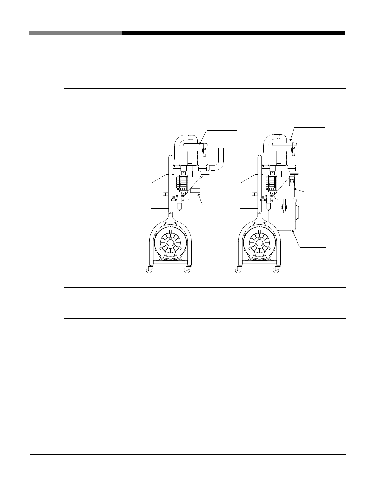
Cartridge filter within filter
case of the suction unit
V type
Filter case
Cap
Filte
Descriptions
1. After removing a catch clip on the filter case, remove the filter
case lid.[①→②]
2. After removing a filter clip,take out the cartridge filter from the
filter case lid to clean.[③→④→⑤]
3. Remove the fine particles that adhere to the filter with a vacuum
cleaner.
4. Be sure to recover after cleaning.
Elbow pipe
②
Filter case lid
Filter hook
④④
①①
⑤
③
Cartridge filter
Filter clip
Catch clip
Filter case
Dust box
VC type
[WO-4841;JL4-V・VC-3~6-38]
1. Install the cartridge filter so that the opening having the packing is
directed toward the filter case lid.
2. If the equipment is used in a state where packing of the cartridge filter
does not closely contact the filter case lid, the fine particles will mix into
the blower and cause blower trouble.
3. Replace with a new cartridge filter, in the case where a damaged
cartridge filter, a cartridge filter that is severely deteriorated, deformed or
is adhered with deposits cannot be removed. Replace when the blower
has trouble and cannot carry out material conveyance, the filter mesh is
clogged, or fine particles result of a damaged part.
- 38 -
CAUTION
Page 43

Maintenance and
inspection item
Discharging dust in suction
unit
Air kit for 3-6 way selector
valve
Chapter 8 Inspection and Maintenance
Descriptions
V type
Remove the cap below the filter case and discharge the accumulated
dust. Be sure to recover after discharging.
VC type
Remove the catch clip on the upper part of the dust box and discharge
the accumulated dust. Be sure to recover after discharging.
* Replace with new packing if the U type packing for the dust box is
severely deteriorated, deformed, discolored or hardened.
Discharge drainage accumulated in the bowl of the air filter by pressing the
drain valve on the lower part of the bowl. Catch drainage with an empty
can.
Stop valve
Air supply port
Air filter
Drain valve
[WO-4841;JL4-V・VC-3~6-39]
- 39 -
Page 44

Maintenance and
inspection item
Air kit for slide gate of
collection hopper
* Only for a suction hopper
type SD control collection
hopper
Chapter 8 Inspection and Maintenance
Descriptions
Pull up the adjusting knob of the filter regulator to unlock, turn the adjusting
knob the to left, and check that the indicated pressure on the pressure
gauge has reached “0 (zero)” and then discharge the drainage
accumulated in the bowl. Drainage can be discharged by pushing the drain
valve of the bowl lower part.
Drainage should be received by an empty can.
Adjustment knob
Pressure gauge
Bowl
Drain valve
[WO-4841;JL4-V・VC-3~6-40]
- 40 -
Page 45

2. Monthly Inspection
Maintenance and
inspection item
Metal screen filter inside the
collection hopper
Open the lid of the collection hopper to take out the filter, and check that it
is not clogged.
If clogged, blow clean dry air to remove the deposits.
* If the deposits cannot be removed even by blowing dry air, use sharp
metal wire.
* Replace with new packing if the packing is severely deteriorated,
deformed, discolored or hardened.
Chapter 8 Inspection and Maintenance
Descriptions
Lid
Packing
Filter
Catch clip
Conveying hose (PVC hose)
Air hose (GL-IV hose)
CAUTION
Exercise sufficient care when handling the filter.
A deformed metal screen filter may cause air leakage, resulting in
conveyance failure.
If the filter is deformed, fix it by tapping it with a soft object such as a
wooden or rubber hammer. If the filter still cannot be fixed, replace it with a
new one.
Inspect each hose connection for suction leakage, and additionally tighten
the hose bands.
* Replace with a new hose if the hose is severely deteriorated, hardened
or damaged.
[WO-4841;JL4-V・VC-3~6-41]
- 41 -
Page 46

Chapter 8 Inspection and Maintenance
- 42 -
[WO-4841;JL4-V・VC-3~6-42]
Maintenance and
inspection item
Descriptions
Check each component of jet
clone
A: Please check that the stopper (M6) on the upper and lower two
points are not loosened, respectively.
※Please retighten the stopper according to the “Stopper adjusting
diagram” on the following page, if loosened.
B: Remove the cover and check that the hexagon socket head locking
screw of the removable cam is not loosened. Simultaneously, open
and close the damper to check that no abnormality for the limit
switch exists.
※Please retighten according to the “Stopper adjusting diagram” on
the following page, if loosened.
C: Please check that the hexagon socket head locking screw fixing
the balance weight is not loosened.
※Tighten the screw for fixing if loosened.
D: Please check that no abnormality for the spring, bolt, nut and
split pin exists.
※If any abnormality is found, please replace it with a new one.
C
D
B
A
A
Page 47

Chapter 8 Inspection and Maintenance
- 43 -
[WO-4841;JL4-V・VC-3~6-43]
Maintenance and
inspection item
Descriptions
Check each component of
jet clone
6mm
A
p
p
r
o
x
i
m
a
t
e
l
y
8
5゚
A
p
p
r
o
x
i
m
a
t
e
l
y
7
0
゚
Stopper adjustment diagram
Upper stopper adjustment
position
Lower stopper
adjustment position
(Clearance 6mm)
Limit switch ON
p
osition
Page 48

Chapter 8 Inspection and Maintenance
- 44 -
[WO-4841;JL4-V・VC-3~6-44]
3. Component adjustment procedure
This section describes the adjustment procedure of the full detecting
device attached to each collection hopper.
1) Jet Clone gate cam
Adjust the gate cam when full is not detected
regardless of whether the material is full.
Step Details of operation
1 Loosen the set-screw with a hexagon rod spanner (2.5mm).
2 Adjust the gate cam position so that the limit switch is ON with the gate
lowering from the horizon by 45-50°.
3 After adjusting the cam, secure it by tightening the set-screw.
2) Balance weight for Jet clone
In a case where material is attached to the damper
due to static electricity, the state shown on the right
is brought about in rare cases. In such a case, adjust
the damper by loosening two locking screws for
the balance weight rearward by 5mm, respectively,
so as to be horizontally positioned. Retighten screws
for fixing after adjustment.
Limit switch
Gate
Set-screw
Page 49

Chapter 8 Inspection and Maintenance
- 45 -
[WO-4841;JL4-V・VC-3~6-45]
3) Suction hopper level switch
If the level switch does not accurately detect the full level for the material used, make a
sensitivity adjustment of the level switch. Adjust the sensitivity according to the specific
gravity of the material.
Step Details of operation
1 Set the control panel power circuit breaker to ON.
2 Remove the lid of the level switch.
3 Change the spring hook position.
Moving the spring toward the HIGH
position causes the sensitivity to increase,
and vice versa.
[Confirmation method]
(1) The spring of the level switch is set up
in the strongest direction.
(2) The material is fed slowly until the blade
of the level switch is filled up with the material.
(3) The adjustment confirmation performs under this condition from the
HIGH to LOW direction step by step. Then, the adjustment is completed
in the position where the blade rotation stops securely.
Page 50

Chapter 8 Inspection and Maintenance
- 46 -
[WO-4841;JL4-V・VC-3~6-46]
4) Suction hopper proximity switch (E2K)
If the proximity switch does not detect the full level, make a sensitivity adjustment of the
proximity switch by the following steps.
Step Details of operation
1 Remove the materials in the collection hopper.
Turn ON the power circuit breaker on the control panel.
2 Confirm that there is no gap of 1mm or more between the end of the proximity
switch and the hopper sight glass.
If there is a gap between them, loosen the fastening screws (2 pieces) of the
proximity switch fitting bracket and adjust the distance between the end of
the proximity switch and the hopper sight glass to approximately 1mm, and
then fix them.
3 Remove the rubber cap at the back of the proximity switch.
4 Perform the following ①, ② and ③ operations while adjusting the
sensitivity adjustment screw with the attached screwdriver.
① Adjust the sensitivity to a point where the sensor switches from ON to OFF
without material (Detection indication lamp turns OFF).
② Adjust the sensitivity to a point where the sensor switches from OFF to ON
with material (Detection indication lamp turns ON).
③ Set the sensitivity adjustment screw at the middle point between the ON to
OFF point ① without material and the OFF to ON point ② with material.
NOTE:
Perform the sensitivity setting with the actually used material. And, when there are
various materials, the ①, ② and ③ operations should be performed with a light
material of appearance specific gravity.
5 Install the rubber cap removed in step 3.
Perform the material conveyance and confirm that the detection indicator
turns on.
Sensitivity
adjustment
Rubber cap
(-side) ←―――②―――――――③―――――――①――→ (+side)
With material Without material
ON (turns ON) ▲ OFF (turns OFF)
Setting point
Detection indication lamp
Page 51

Chapter 8 Inspection and Maintenance
4. Operation check procedure of 3 – 6 way selector valve
Manually operate the 3 – 6 way selector valve and describe the Operation check
the Operation check procedure according to the steps.
Step Details of operation
Turn OFF the power breaker on the rear face of the control panel.
1
2
Supply dry compressed air of –0.3 MPa - 0.9 MPa to the air kit of the 3-6 way selector
valve.
3
Press the manual button of the solenoid valve.
Manual button
When the manual button of the solenoid valve is pressed, the air cylinder operates.
[WO-4841;JL4-V・VC-3~6-47]
- 47 -
Page 52

Chapter 8 Inspection and Maintenance
5. Operation check procedure of automatic slide gate
In the case of the suction hopper type SD control collection hopper, manually operate the
automatic slide gate. The methods for checking the operation are described according to the
steps.
Step Details of operation
Turn “OFF” the control panel power circuit breaker.
1
Supply dry compressed air of 0.4 MPa to 0.5 MPa to the air kit of the automatic slide
2
gate.
3
Press the manual button on the solenoid valve. The air cylinder starts to operate.
Stop valve
ストップバルブ
Movable part
可動部
Filter regulator
フィルター
レギュレーター
Main body of automatic slide gate
自動スライドダンパー本体
Cylinder
シリンダー
Safety cover
安全カバー
CAUTION
注 意
WATCH YOUR FINGERS
指 づ め 注 意
1. 運転中は指や手を可動部に入
1.Do not place fingers or hands in movable
sections during operations.
れるな。
2.Take care to avoid lacerations to fingers or
2. 裂傷や骨折するおそれがあ
hands and danger of them being broken.
る。
3.When performing cleanup of or inspection
3. 清掃・点検作業は電源を OFF
turn power OFF and shut off air supply.
DO NOT SOIL OR PEEL THIS LABEL
このラベルをはがしたり、よごしたりしないこと。 6-21-1
にしてエアー供給源を遮断して
WARNING
Do not place fingers or hands into the movable parts (slide part) during operation.
○
Tears or bone fractures may result.
○ Never operate with the cover of the movable part removed.
○ Never operate with material caught in the slide damper. Failure may result.
[WO-4841;JL4-V・VC-3~6-48]
- 48 -
Page 53

Chapter 9 Troubleshooting
This chapter describes troubleshooting of the product. Check before requesting
repair.
Before inspection, be sure to stop the operation and set the control panel power
circuit breaker and the primary power supply to “OFF.”
Error by digital display on control panel
Code
“E 0”
Memory error
“E 3”
Conveying
blower overload
error
Location to be
checked
Check the control
board.
Check that
material is not
clogged in the
conveying hose.
Check that the
thermal relay in
the control panel
is set to the rated
value.
Action Precaution
・ Restart.
・ Turn “OFF” the power
circuit breaker once, and
turn it “ON” again.
・ Remove the material in the
conveying hose.
・ Adjust the secondary air
intake amount with the
secondary air adjustment
ring on the suction nozzle
at the end of the conveying
hose.
・ Set the thermal relay to the
rated value.
・ Press the reset button for
the thermal relay to reset
the alarm.
WARNING
・ Be sure to turn “OFF” the power
supply of your facility before
carrying out work.
・ If the “E0” is displayed even after
restarting, the control board has
failed.
・ Contact your local Matsui SDI
dealer.
・ When the suction part (metal
mesh) on the secondary air
adjustment ring is clogged, blow
clean dry air to remove the
deposits.
・ Be sure to turn “OFF” the power
supply of your facility, and then set
to the rated value of the thermal
relay and reset the alarm with the
reset button.
“E 14”
Control board
error
Check the control
board.
[WO-4841;JL4-V・VC-49]
・ Restart.
・ Turn “OFF” the power
circuit breaker once, and
turn it “ON” again.
- 49 -
・ Be sure to turn “OFF” the power
supply of your facility before
carrying out work.
・ If the “E14” is displayed even after
restarting, the control board has
failed.
・ Contact your local Matsui SDI
dealer.
Page 54

A
Code
“E 15”
larm for filter
cleaning
“E 21”
No. 1 Conveying
error
“E 22”
No. 2 Conveying
error
Location to be
checked
Clean the cartridge
filter and check
powder dust in the
dust box.
Check that material is
not clogged in the
conveying hose in the
No. 1 direction.
Check the limit switch
for the level switch in
the No. 1 direction (Jet
Clone type), E2K for
the suction hopper
type, and level switch
for level switch type.
Check that material is
not clogged in the
conveying hose in the
No. 2 direction.
Check the limit switch
for the level switch in
the No. 2 direction (Jet
Clone type), E2K for
the suction hopper
type, and level switch
for level switch type.
Action Precaution
・ Clean the filter, and
dispose powder dust
in the dust box. (see
Chapter 8 Inspection
and Maintenance).
・ Set the dust cleaning
count (dUP) to “0” to
reset.
・ Remove the material
in the conveying hose.
・ Adjust the secondary
air intake amount with
the secondary air
adjustment ring on the
suction nozzle at the
end of the conveying
hose.
・ See “Blower does not
rotate” in the next
item.
・ Remove the material
in the conveying hose.
・ Adjust the secondary
air intake amount with
the secondary air
adjustment ring on the
suction nozzle at the
end of the conveying
hose.
・ See “Blower does not
rotate” in the next
item.
Chapter 9 Troubleshooting
・ If the cartridge filter is damaged or
deposits cannot be removed,
replace the filter.
・ Contact your local Matsui SDI
dealer for a new filter.
・ When the suction part (metal
mesh) on the secondary air
adjustment ring is clogged, blow
clean dry air to remove the
deposits.
・ See “Blower does not rotate” in
the next item.
・ When the suction part (metal
mesh) on the secondary air
adjustment ring is clogged, blow
clean dry air to remove the
deposits.
・ See “Blower does not rotate” in
the next item.
[WO-4841;JL4-V・VC-50]
- 50 -
Page 55

Code
“E 23”
No. 3 Conveying
error
“E 24”
No. 4 Conveying
error
Location to be
checked
Check that material is
not clogged in the
conveying hose in the
No. 3 direction.
Check the limit switch
for the level switch in
the No. 3 direction (Jet
Clone type), E2K for
the suction hopper
type, and level switch
for level switch type.
Check that material is
not clogged in the
conveying hose in the
No. 4 direction.
Check the limit switch
for the level switch in
the No. 4 direction (Jet
Clone type), E2K for
the suction hopper
type, and level switch
for level switch type.
Action Precaution
・ Remove the material
in the conveying hose.
・ Adjust the secondary
air intake amount with
the secondary air
adjustment ring on the
suction nozzle at the
end of the conveying
hose.
・ See “Blower does not
rotate” in the next
item.
・ Remove the material
in the conveying hose.
・ Adjust the secondary
air intake amount with
the secondary air
adjustment ring on the
suction nozzle at the
end of the conveying
hose.
・ See “Blower does not
rotate” in the next
item.
Chapter 9 Troubleshooting
・ When the suction part (metal
mesh) on the secondary air
adjustment ring is clogged, blow
clean dry air to remove the
deposits.
・ See “Blower does not rotate” in
the next item.
・ When the suction part (metal
mesh) on the secondary air
adjustment ring is clogged, blow
clean dry air to remove the
deposits.
・ See “Blower does not rotate” in
the next item.
[WO-4841;JL4-V・VC-51]
- 51 -
Page 56

Code
“E 25”
No. 5 Conveying
error
“E 24”
No. 6 Conveying
error
Location to be
checked
Check that material is
not clogged in the
conveying hose in the
No. 5 direction.
Check the limit switch
for the level switch in
the No. 5 direction (Jet
Clone type), E2K for
the suction hopper
type, and level switch
for level switch type.
Check that material is
not clogged in the
conveying hose in the
No. 6 direction.
Check the limit switch
for the level switch in
the No. 6 direction (Jet
Clone type), E2K for
the suction hopper
type, and level switch
for level switch type.
Action Precaution
・ Remove the material
in the conveying hose.
・ Adjust the secondary
air intake amount with
the secondary air
adjustment ring on the
suction nozzle at the
end of the conveying
hose.
・ See “Blower does not
rotate” in the next
item.
・ Remove the material
in the conveying hose.
・ Adjust the secondary
air intake amount with
the secondary air
adjustment ring on the
suction nozzle at the
end of the conveying
hose.
・ See “Blower does not
rotate” in the next
item.
Chapter 9 Troubleshooting
・ When the suction part (metal
mesh) on the secondary air
adjustment ring is clogged, blow
clean dry air to remove the
deposits.
・ See “Blower does not rotate” in
the next item.
・ When the suction part (metal
mesh) on the secondary air
adjustment ring is clogged, blow
clean dry air to remove the
deposits.
・ See “Blower does not rotate” in
the next item.
[WO-4841;JL4-V・VC-52]
- 52 -
Page 57

Power circuit breaker trips.
Location to be checked Action Precaution
Check that foreign matter is not
caught in the blower fan.
Check that the magnetic switch
(MS-1) in the control panel
operates normally.
Check that the power circuit is
not short-circuited.
Remove the fan cover to
remove foreign matter.
Replace the magnetic switch
(MS-1).
Eliminate the short-circuit. Entrust Matsui SDI or your employee who
Turn “OFF” the primary power supply and
power circuit breaker before carrying out
work.
Tolerance: 1,000,000 times
Even if it is normal, replace by the time
the above times are reached or within 2
years after starting use.
Entrust Matsui SDI or your employee who
has sufficient working knowledge of
electricity to carry out inspection or
exchange, since the operation includes
the potential for failure or danger.
has sufficient working knowledge of
electricity to carry out inspection or
exchange, since the operation includes
the potential for failure or danger.
Chapter 9 Troubleshooting
[WO-4841;JL4-V・VC-53]
- 53 -
Page 58

Chapter 9 Troubleshooting
Operation panel does not turn on.
NOTE
When not in operation, a decimal point at the bottom of the digital display on
the operation panel turns on, indicating that power is “ON.”
Location to be checked Action Precaution
Check that the power circuit
breaker on the control panel is
“ON.”
Check that the glass-tube fuse
(F-1) in the control panel has
not burned out.
Turn “ON” the power breaker. If switching does not function properly,
replace the power breaker.
Entrust Matsui SDI or your employee who
has sufficient working knowledge of
electricity to carry out inspection or
exchange, since the operation includes
the potential for failure or danger.
Replace the glass-tube fuse
(F-1).
Check that the power circuit is
not short-circuited.
Turn “OFF” the primary power supply and
power circuit breaker before carrying out
work.
Entrust Matsui SDI or your employee who
has sufficient working knowledge of
electricity to carry out inspection or
exchange, since the operation includes
the potential for failure or danger.
Blower does not rotate.
Location to be checked Action Precaution
Check that the connecting
terminal of the power cord is
securely tightened.
Check that the magnetic switch
(MS-1) in the control panel
operates normally.
Securely tighten the connecting
terminal.
Replace the magnetic switch
(MS-1).
Turn “OFF” the primary power supply
before carrying out work.
Tolerance: 1,000,000 times
Even if it is normal, replace by the time
the above times are reached or within 2
years after starting use.
Entrust Matsui SDI or your employee who
has sufficient working knowledge of
electricity to carry out inspection or
exchange, since the operation includes
the potential for failure or danger.
[WO-4841;JL4-V・VC-54]
- 54 -
Page 59

Blower does not rotate.
Location to be checked Action Precaution
Check that foreign matter is not
caught in the blower fan.
Check that the Jet Clone limit
switch operates normally.
* Only when the Jet Clone
type limit type collection
hopper is used.
Check that the Jet Clone gate
can is properly adjusted.
* Only when the Jet Clone
type limit type collection
Material
hopper is used.
Check that the suction hopper
proximity switch detects
normally.
* Only when the suction
hopper type E2K control is
used.
Check that the suction hopper
level switch detects normally.
* Only when the suction
hopper type level switch
control or SD control
collection hopper is used.
Remove the fan cover to
remove foreign matter.
Turn “OFF” the primary power supply and
power circuit breaker before carrying out
work.
Replace the limit switch. For purchase of the limit switch and type,
contact Matsui SDI.
Refer to Chapter 8 Inspection
A condition when the limit switch is “ON.”
and Maintenance to adjust the
gate cam.
Refer to Chapter 8 Inspection
and Maintenance to adjust the
For purchase of the proximity switch and
type, contact Matsui SDI.
sensitivity of the proximity
switch.
If the proximity switch does not
operate normally even after the
sensitivity adjustment, replace
it.
Refer to Chapter 8 Inspection
and Maintenance to adjust the
For purchase of the level switch and
type, contact Matsui SDI.
sensitivity of the level switch.
If the level switch does not
operate normally even after the
sensitivity adjustment, replace
it.
Chapter 9 Troubleshooting
材料
Material
[WO-4841;JL4-V・VC-55]
- 55 -
Page 60

The blower rotates but does not suction air.
Location to be checked Action Precaution
Check the blower for reverse
rotation.
* The blower rotates in
reverse if air is suctioned
from the exhaust port of the
blower.
Check that the suction hopper
damper is securely closed.
* Only when the suction
hopper type SD control
collection hopper is used.
Check that external air is
suctioned from the connection
end of the conveying hose or
suction hose.
Check that the conveying hose
is not clogged with material.
Refer to Chapter 3 Installation
to rotate the blower forward.
Securely connect the power
connector for the
electromagnetic valve.
If the damper still does not
close, replace the
electromagnetic valve.
Securely tighten the hose
clamps.
Remove the material from the
conveying hose.
Increase the amount of
secondary intake air by
adjusting the secondary air
adjustment ring of the suction
nozzle at the end of the
conveying hose.
Turn “OFF” the primary power supply and
power circuit breaker before carrying out
work.
For purchase of the electromagnetic
valve and type, contact Matsui SDI.
Entrust Matsui SDI or your employee who
has sufficient working knowledge of
electricity to carry out inspection or
exchange, since the operation includes
the potential for failure or danger.
If any of the hoses are broken, replace
them with new ones.
For purchase of the hose and type,
contact Matsui SDI.
If the suction part (metal mesh part) of
the secondary air adjustment ring is
clogged, blow clean dry air to remove
deposits.
Chapter 9 Troubleshooting
[WO-4841;JL4-V・VC-56]
- 56 -
Page 61

The blower rotates but does not suction air.
Location to be checked Action Precaution
Check that the lid of the
collection hopper is securely
fitted.
Check that the metal mesh filter
inside the collection hopper is
not clogged.
Check that the cartridge filter
inside the filter case is not
clogged.
Check that the 2-way selector
valve is properly selected.
Fit the packing and fix the lid
with catch clips.
Blow clean dry air to the metal
mesh filter to remove deposits.
After removing powder dust
remaining inside of the
cartridge filter, blow clean dry
air to remove deposits.
Refer to Chapter 8 Inspection
and Maintenance to check the
operation of the
electromagnetic valve.
If the electromagnetic valve
does not properly operate,
dismantle and clean it or
replace it.
If the packing is significantly deteriorated,
deformed, discolored or hardens, replace
it with a new one.
For purchase of the packing and type,
contact Matsui SDI.
If the deposits cannot be removed by the
procedure described at the left, use a
wire with a sharp edge.
Do not deform the metal mesh filter.
If the deposits cannot be removed due to
severe deterioration of the cartridge filter,
replace it with a new one.
In addition, if the packing is significantly
deteriorated, deformed, discolored or
hardens, replace it with a new one.
For purchase of the packing and
cartridge filter and type, contact Matsui
SDI.
For purchase of the electromagnetic
valve and type, contact Matsui SDI.
Chapter 9 Troubleshooting
[WO-4841;JL4-V・VC-57]
- 57 -
Page 62

No full level signal of the collector appears.
Location to be checked Action Precaution
Check that the Jet Clone limit
switch operates normally.
* Only when the Jet Clone
type limit type collection
hopper is used.
Check that the Jet Clone gate
cam is properly adjusted.
* Only when the Jet Clone
type limit type collection
Material
hopper is used.
Check that the Jet Clone gate is
completely opened.
* Only when the Jet Clone
type limit type collection
hopper is used.
Check that the suction hopper
proximity switch detects
normally.
* Only when the suction
hopper type E2K control is
used.
Check that the suction hopper
level switch detects normally.
* Only when the suction
hopper type level switch
control or SD control
collection hopper is used.
Replace the limit switch. For purchase of the limit switch and type,
contact Matsui SDI.
Refer to Chapter 8 Inspection
A condition when the limit switch is “ON.”
and Maintenance to adjust the
gate cam.
Check the end of the damper
solenoid and repair any
Contact Matsui SDI for replacement of
the end.
abnormality.
Refer to Chapter 8 Inspection
and Maintenance to adjust the
For purchase of the proximity switch and
type, contact Matsui SDI.
sensitivity of the proximity
switch.
If the proximity switch does not
operate normally even after the
sensitivity adjustment, replace
it.
Refer to Chapter 8 Inspection
and Maintenance to adjust the
For purchase of the level switch and
type, contact Matsui SDI.
sensitivity of the level switch.
If the level switch does not
operate normally even after the
sensitivity adjustment, replace
it.
Chapter 9 Troubleshooting
材料
Material
[WO-4841;JL4-V・VC-58]
- 58 -
Page 63

Chapter 10 List of Consumables
Code
No.
00427 #38
00427 #38
00428
12735 #38
12736
-
-
- Cartridge filter Matsui Mfg Co. MXF-16SP-G4 1 Every year
-
Part name Maker Model/Material Qty
5m
/one
direction
Conveying hose
(PVC hose)
Suction hose
(GL-IV hose)
Packing
(for filter case lid)
Packing
(for dust hopper lid)
Glass-tube fuse
(inside control panel)
Tigers Polymer
Co.
#50
Tigers Polymer
Co.
Matsui Mfg Co. NBR U-packing 1 Every year
Matsui Mfg Co. NBR U-packing 1 Every year
Commercially
available
#65
250V-1A 1 Every six months
10m
/one
direction
10m
/one
direction
5m
/one
direction
NOTE
1. The replacement interval varies with the conditions of operation.
2. The hoses shown above are of the standard type.
Recommended
Replacement
interval
Every year
Every year
[WO-4841;JL4-V・VC-3~6-59]
- 59 -
Page 64

Chapter 12 Option
This chapter describes physical properties which customers should understand
when operating the product.
Model JL4- 4 (V, VC) 5 (V, VC) 6 (V, VC)
Blower type
Maximum static pressure
-kPa
Maximum air flow rate
3
m
/min
Maximum output
kW
* Conveying
capacity
kg/h
Conveying hose (PVC hose) inner
diameter mm
Suction hose (GL-IV hose) inner
diameter mm
Standard combined Jet Clone
J, A version RB40-520 RB40-620 RB50-620
U version RB40-53U RB40-63U RB50-63U
50Hz 17 18 22
60Hz 18 21 24
50Hz 2.4 2.4 3.5
60Hz 2.8 2.8 3.8
50Hz 0.9 1.1 2.2
60Hz 1.15 1.5 2.55
5m 50Hz 200 390 850
60Hz 250 440 910
10m 50Hz 170 300 740
60Hz 220 360 820
20m 50Hz 120 230 590
60Hz 170 300 700
30m 50Hz 100 180 520
60Hz 150 250 630
38 38 50
38 38 65
JC-6 JC-9 JC-18
200V AC 3-phase 50/60Hz, 220V AC 3-phase 60Hz J version
(A)
15 15 20
380/400/415V AC 3-phase 50/60Hz
10
10
10
10
10
15
230V AC 3-phase 60Hz, 460V AC 3-phase 60Hz
15
10
15
10
20
10
Power (V) (Hz)
Capacity (A)
A version
(A)/50Hz
(A)/60Hz
U version
(A)/230V
(A)/460V
1. The above conveying capacity shall be obtained under the following conditions.
1) Resin used: ABS virgin pellets with an apparent specific gravity of 0.63.
2) Suction distance: 5m. The conveying distance (5 to 30m) includes a vertical distance of 3m.
3) Hose used: PVC hose, Nozzle used: made by Matsui
4) Standard combined Jet Clone
2. The conveying capacity of the equipment varies with the shape and specific gravity of the virgin material,
the temperature, the material and bend of the conveying pipe, the types of suction nozzle and collection box,
and the control procedures for the collection hopper.
- 60 -
[WO-4841;JL4-V・VC-3~6-60]
Page 65

Chapter 12 Option
The following options are available for this equipment.
Please make sure that correct options are installed
2A
2B
5
2B
1
ELB-1
2C
* The unit shown above is a suction unit of the type JL4-VC
CR-1
4
Tr-0
Inside of control panel
[WO-4841;JL4-V・VC-3~6-61]
- 61 -
Page 66

Chapter 12 Option
①: Leakage circuit breaker
The leakage circuit breaker, if attached to the power circuit breaker, will protect the equipment against
a ground fault, an overload or short-circuit, thus preventing electric shock hazards.
(E) (R) (S) (T)
Symbol Name
JL4-4V/VC NV30-KC 3P 15A 30mA
ELB-1
・ The leakage circuit breaker is for supplied voltage of 200V AC to 220V AC. The breaker cannot be
attached for other voltages.
・ When the leakage breaker is attached, a no-fuse breaker (NFB-1) is not attached.
Leakage circuit
breaker for motor
protection
Mitsubishi
Electric Corp.
JL4-6V/VC
三相交流電源 50/60Hz
AC 3-phase power supply 50/60Hz
ELB-1
Maker
JL4-5V/VC NV30-KC 3P 15A 30mA
NOTE
Model
NV30-KC 3P 20A 30mA
②: Alarm
The alarm can be chosen for only one of the following, 2A revolving alarm lamp, 2B buzzer lamp, 2A+2B
revolving alarm lamp with buzzer and 2C alarm output.
2A: Alarm lamp
At the time of dusting operation, the alarm lamp turns on, alerting operators in a wide working area.
Alarm
Symbol Name Maker Model
PTL-1 Revolving warning light
* The color of revolving alarm lamp can be chosen from red or yellow.
PTL-1
Arrow Electronics
Co.
Revolving
warning light
AP-200 (R, Y)
[WO-4841;JL4-V・VC-3~6-62]
- 62 -
Page 67

A
A
2B: Alarm buzzer
At the time of dusting operation, the buzzer sounds, alerting operators in a wide working area.
The buzzer sound can be stopped by a pushbutton.
1
Symbol Name Maker Model
BZ Buzzer Fuji electric DR22B5-MB
PB-R1 Pushbutton Fuji electric AR22F0R-10B
2A+2B: Alarm display with buzzer
At the time of dusting operation, the buzzer sounds and alarm display lamp turns on, alerting
operators in a wide working area.
The buzzer sound can be stopped by a pushbutton.
1
Symbol Name Maker Model
21
21
22
22
PB-R1
CR-1
PB-R1
CR-1
PTL-1
22A
22B
22A
22B
CR
BZ
CR
BZ
1
Chapter 12 Option
Buzzer reset
ブザーリセット
2
1
Alarm
警 報
Buzzer reset
ブザーリセット
2
Alarm
警 報
PTL-1 Revolving alarm lamp Arrow Electronics Co. AP-200 (R, Y)
BZ Buzzer Fuji electric DR22B5-MB
PB-R1 Pushbutton Fuji electric AR22F0R-10B
* The color of the revolving alarm lamp can be chosen from red or yellow.
2C: Alarm output
The alarm signal is delivered to the metal connector (CN-1) on the lower part of the control panel.
(Non-voltage relay output: load resistance, 250V AC, 1A Max.)
Symbol Name Maker Model
Metal connector
[WO-4841;JL4-V・VC-3~6-63]
larm
- 63 -
Nanaboshi Electric Mfg. Co.
larm output
NJC-202-PF/AdM
Page 68

③: Batch conveyance
If the automatic slide gate is installed below the receiver tank, material can be stopped during conveyance.
The blower stops after blowing air into the conveying pipe.
Symbol Name
Automatic slide gate MATSUI ASD φ70 automatic gate
Chute MATSUI SUS-304
Suction box MATSUI SUS-304
④: Operating voltage 100V AC
The supplied voltage 200V AC is transformed down to an operating voltage of 100V AC by the internal
transformer.
Symbol Name Maker Model
Tr-0 Transformer
Maker
Urakawa
Transformer Mfg.
Co.
Chapter 12 Option
Model
ZTN35 × 50-36358
NOTE
For operating voltage of 100V AC, coils of 200V AC for the magnetic switch, solenoid coil, level switch and
buzzer are replaced by those of 100V AC.
⑤: Large dust hopper (JL4-VC TYPE ONLY)
When loading the material containing a large amount of powder, we recommend a large dust hopper.
[WO-4841;JL4-V・VC-3~6-64]
- 64 -
Page 69

A
B
C
D
REFERENCEREQ.D MATERIALDESCRIPTIONITEM NO.
125
3.53.5
118
Standard dwg.
標準図
543
189754
DWG.
NO.
G2842-JLD2
NAME
Reset
/Function /Parameter
PV SV
Conveyance
Discharge
/User Setting
Jet Loader
/Engineering Setting
2
No.
1
No.
Stop
Run
Feed to
Setting
SV
JUN/9/2004
PLANE
TRIGONOMETRY
700203
290
CODE NO.
1:1
SCALE
FORM
DATE
KIMURA
--
APPROVED BY
DSGND(CHKD)BY
UNIT mm
T.OONO
DRAWN BY
2
APPD
CHKD
23 130 130 7
I
O
N
CONTENTSMARK
元図 DWG. NO. A301138
1
DATE
R
E
V
I
S
Page 70

A
B
C
D
543
TRIGONOMETRY
APPD
2
CHKD
SCALE
APPROVED BY
DRAWN BY
DSGND(CHKD)BY
1
CONTENTSMARK
R
E
V
I
S
I
O
N
DATE
FORM
DATE
UNIT mm
NAME
REFERENCEREQ.D MATERIALDESCRIPTIONITEM NO.
CODE NO.
PLANE
NO.
DWG.
1:6
JL4
700203
--
元図 DWG. NO. A301097
Standard dwg.
標準図
275
75 80
1
240 235
475
360
270
200
TR-1
130
180 195
405
1515
295
310
3
4
2
5
1
CR
MC-1
MP-1
FF
01
02
1
F
Tr-0
T05013
M.TAKANO
NISHI
SEP/22/2005
1
TR-1
2
3
4
5
SW-1
PB-1
BZ
CB-1
MP-1
MC-1
Tr-0
F-01,02
F-1
Contoroler(1,2WAY Type)
Contoroler(3-6WAY Type)
1
Matsui
G2842-JLD2
1
Matsui
1
1
1
1
Matsui
1
1
1
1
G2842-JLD6
Operation ON-OFF
EATON
8006K23NIV2
Alarm Silence
Alarm
Circuit board
Motor Protectors
Allen-Bradley
Contactors
Allen-Bradley
Transformer
Signal
241-8-2554
2
Bussman
Fuses
Fuses
2A
TB-1
Model
Voltage
Motor Protectors
JL4-4
JL4-5
Fuses
AC460V
AC230V
AC460V
FNQ-R-2
FNQ-R-1
FNQ-R-2
FNQ-R-1
AC230V
AC460V
FNQ-R-2
FNQ-R-1
AC230V
JL4-6
1
CR-1
Omron
MY-2
Relay
140-C2E-B63(4.8A)
140-C2E-B25(2.5A)
140-C2E-B63(5.8A)
140-C2E-B40(2.9A)
140-C2E-C10(9.2A)
140-C2E-B63(4.6A)
100-C09D10
GE
Mallory
P9XPNN & P9B10VN
SC110
Page 71

A
B
C
D
54321
PLANE
TRIGONOMETRY
CODE NO.
APPDCHKD
SCALE
APPROVED BY
DRAWN BY
DSGND(CHKD)BY
CONTENTSMARK
REVISION
DATE
FORM
DATE
UNIT mm
DWG.
NO.
NAME
JL4
CIRCUIT DIAGRAM 1
1
2
操作電源
PE L1 L2 L3
THREE PHASE ALTERNATIN CURRENT
OPETATION POWER SUPPLY
Tr-1
1
2
3
4
5
6
CN-0 CN-1
CN-2
TR-1
BLACK/黒
BROWN/茶
RED/赤
YELLOW/黄
GREEN/緑
0V
100V
110V
200V
220V
E
WHITE/白
BLUE/青
ORANGE/橙
M1
U1
V1
W1
R1
S1
T1
ブロワー
BLOWER
M1TYPE/型式
--
元図 DWG. NO. A301108
JL4-4V,VC-U
JL4-5V,VC-U
Standard dwg.
標準図
F-01
F-02
R2
S2
三相交流電源 AC460/230V 60Hz
1.15kW
1.50kW
2.55kW
AC230V
2&5/4&1 4&2
AC460V
F-1
1B
1A
150VA
SW-1
JL4-6V,VC-U
MP-1
MC-1
T05014
M.TAKANO
NISHI
SEP/23/2005
Tr-0
Tr-0 JUMPER
Page 72

MC-1
A
B
C
D
54321
PLANE
TRIGONOMETRY
CODE NO.
APPDCHKD
SCALE
APPROVED BY
DRAWN BY
DSGND(CHKD)BY
CONTENTSMARK
REVISION
DATE
FORM
DATE
UNIT mm
DWG.
NO.
NAME
JL4
CIRCUIT DIAGRAM 2
OPTION
--
元図 DWG. NO. A301110
700203
Standard dwg.
標準図
T05015
M.TAKANO
NISHI
SEP/23/2005
TB2
1
2
3
4
5
6
7
8
9
+12V
INPUT
+12V
0V
INPUT
0V
+12V
INPUT
0V
TB1
1
2
D14
D15
D17
D18
警報入力
ALARM INPUT
NO. 2 LEVEL SIGNAL
NO. 1 LEVEL SIGNAL
NO. 1 レベル計
NO. 2 レベル計
D12
D13
D16
D19
CN1
CONTROL BOARD
TR-1
I/O-BOARD
MP-1
22
21
1
BZ
CR
1
CR-1
PB-1
22A
22B
警報
ALARM
ブザーリセット
BUZZER RESET
3
23
23A
ブロワー
MP-1
1
MC
BLOWER
オプション
4
5
6
SOL-1
SOL-2
24
26
7
8
9
27
28
29
SOL-3
SOL-4
SOL-5
SOL-6
10
1 2
NO.1 排出弁
NO.2 排出弁
NO.1 DISCHARGE VALVE
NO.2 DISCHARGE VALVE
NO.2 BRANCH VALVE
NO.2 方向切替弁
バッチダンパー
BATCH DAMPER
原料切替弁
MATERIAL CHANGE VALVE
NO.1 BRANCH VALVE
NO.1 方向切替弁
JSV
26A
No.2ジェットセレクタ
No.2 JET SELECTOR
JSV
29A
No.1 JET SELECTOR
No.1ジェットセレクタ
MC-1
Page 73

TB1
1
2
A
B
C
D
54321
PLANE
TRIGONOMETRY
CODE NO.
APPDCHKD
SCALE
APPROVED BY
DRAWN BY
DSGND(CHKD)BY
CONTENTSMARK
REVISION
DATE
FORM
DATE
UNIT mm
DWG.
NO.
NAME
JL4
TB2
1
2
3
4
5
6
7
8
9
+12V
INPUT
+12V
0V
INPUT
0V
+12V
INPUT
0V
CONTROL BOARD
TR-1 I/O-BOARD
CN1
+12V
INPUT
0V
10
11
12
NO. 3 LEVEL SIGNAL
NO. 3 レベル計
NO. 4 LEVEL SIGNAL
NO. 4 レベル計
NO. 5 LEVEL SIGNAL
NO. 5 レベル計
NO. 6 LEVEL SIGNAL
NO. 6 レベル計
D23
D21
D22
D24
D25
D26
D27
D28
D29
D30
D31
D32
NO.3 DISCHARGE VALVE
NO.3 排出弁
NO.3 BRANCH VALVE
NO.3 方向切替弁
41
42
SOL-7
SOL-8
--
元図 DWG. NO. A301140
700203
Standard dwg.
標準図
JSV
JSV
JSV
JSV
NO.6 方向切替弁
NO.6 BRANCH VALVE
NO.6 排出弁
NO.6 DISCHARGE VALVE
NO.5 方向切替弁
NO.5 BRANCH VALVE
NO.5 排出弁
NO.5 DISCHARGE VALVE
NO.4 DISCHARGE VALVE
NO.4 BRANCH VALVE
NO.4 方向切替弁
NO.4 排出弁
SOL-14
SOL-13
48
47
8
7
SOL-12
SOL-11
46
45
6
5
SOL-9
43
3
SOL-10
44
4
9
TB1
1
2
3
1 2
42A
44A
No.3 JET SELECTOR
No.3ジェットセレクタ
No.4 JET SELECTOR
No.4ジェットセレクタ
No.5 JET SELECTOR
No.5ジェットセレクタ
No.6 JET SELECTOR
No.6ジェットセレクタ
MC-1
MC-1
MC-1
MC-1
T05016
CIRCUIT DIAGRAM 3
M.TAKANO
NISHI
OCT/19/2005
46A
48A
Page 74

A
B
C
D
543
PLANE
TRIGONOMETRY
APPD
2
CHKD
SCALE
APPROVED BY
DRAWN BY
DSGND(CHKD)BY
1
CONTENTSMARK
R
E
V
I
S
I
O
N
DATE
FORM
DATE
UNIT mm
DWG.
NO.
NAME
JL4
D32
D29
D26
D23
D19
D16
D31
D28
D25
D22
D18
D15
No.6 レベル計
No.6 LEVEL SWITCH
No.5 レベル計
No.5 LEVEL SWITCH
No.4 レベル計
No.4 LEVEL SWITCH
No.3 レベル計
No.3 LEVEL SWITCH
No.2 レベル計
No.2 LEVEL SWITCH
No.1 レベル計
No.1 LEVEL SWITCH
LV-6(H)
LV-5(H)
LV-4(H)
LV-3(H)
LV-2(H)
LV-1(H)
21
IN CASE OF LEVEL SWITCH CONTROL
レベル計制御の場合
2
1
IN CASE OF LIMIT SWITCH CONTROL
リミットスイッチ制御の場合
D16D15
D19D18
D23D22
D26D25
D29D28
D32D31
LS-1
LS-2
LS-3
LS-4
LS-5
LS-6
E2K-1
E2K-2
E2K-3
E2K-4
E2K-5
E2K-6
-+
D14
D17
D21
D24
D27
D30
D15
D18
D22
D16
D19
D23
D25
D26
D28
D29
D32
-+
-+
-+
-+
-+
No.2 PROXIMITY SWITCH
No.2 近接スイッチ
No.3 PROXIMITY SWITCH
No.3 近接スイッチ
No.4 PROXIMITY SWITCH
No.4 近接スイッチ
No.1 PROXIMITY SWITCH
No.1 近接スイッチ
No.5 PROXIMITY SWITCH
No.5 近接スイッチ
No.6 PROXIMITY SWITCH
No.6 近接スイッチ
No.1 LEVEL SIGNAL
No.1 レベル信号
No.2 レベル信号
No.2 LEVEL SIGNAL
No.3 レベル信号
No.3 LEVEL SIGNAL
No.4 レベル信号
No.4 LEVEL SIGNAL
No.5 レベル信号
No.5 LEVEL SIGNAL
No.6 レベル信号
No.6 LEVEL SIGNAL
静電容量形近接センサー(DC)制御の場合
IN CASE OF CAPACITIVE PROXIMITY SENSOR(DC) CONTROL
IN CASE OF PHOTOELECTRIC SENSOR CONTROL
光電スイッチ制御の場合
PHF-1
PHR-1
D16
D15
D14
+-
+-
D17 D19
D18
PHF-2
PHR-2
+-
+-
+-
+-
PHF-3
PHR-3
PHF-4
PHR-4
PHF-5
PHR-5
PHF-6
PHR-6
D21 D23
D22
D24
D25
D26
D27
D28
D29
D30
D31
D32
No.6 レベル計
No.6 LEVEL SWITCH
No.5 レベル計
No.5 LEVEL SWITCH
No.4 レベル計
No.4 LEVEL SWITCH
No.3 レベル計
No.3 LEVEL SWITCH
No.2 レベル計
No.2 LEVEL SWITCH
No.1 レベル計
No.1 LEVEL SWITCH
--
元図 DWG. NO. A301141
700203
Standard dwg.
標準図
E2K-2
CR-S2
E2K-3
CR-S3
E2K-4
CR-S4
E2K-5
CR-S5
No.1 近接スイッチ
No.1 PROXIMITY SWITCH
E2K-6
No.2 PROXIMITY SWITCH
No.2 近接スイッチ
No.3 PROXIMITY SWITCH
No.3 近接スイッチ
No.4 PROXIMITY SWITCH
No.4 近接スイッチ
No.5 PROXIMITY SWITCH
No.5 近接スイッチ
No.6 PROXIMITY SWITCH
No.6 近接スイッチ
E2K-1
CR-S1
CR-S6
2S1
2S2
2S3
2S4
2S5
2S6
D31
1
1
2
2
D15
D18
D22
D25
D28
D31
CR
S2
CR
S3
CR
S4
CR
S5
CR
S1
CR
S6
D16
D19
D23
D26
D29
D32
静電容量形近接センサー(AC)制御の場合
IN CASE OF CAPACITIVE PROXIMITY SENSOR(AC) CONTROL
MAI STYLE
T05017
OCT/19/2005
M.TAKANO
CODE NO.
NISHI
Page 75

GLASS TUBE VACUUM HOPPER
ピン番号
PIN NO.
FEED TO
NO.1 NO.2 NO.3 NO.4
1
2
3
4
NO.5 NO.6
D15
D16
D18
D19
D22
D23
D25
D26
D28
D29
D31
D32
CN-L1~L6
222222
111111
CN-L1~L6
CN-S1~S6
LGVH-5,10,15,20
ピン番号
PIN NO.
FEED TO
NO.1 NO.2 NO.3 NO.4
1
2
3
4
NO.5 NO.6
24
222222
25 41 43 45 47
D15
D16
D18
D19
D22
D23
D25
D26
D28
D29
D31
D32
CN-S1~S6
JC
EGVH/MVH/APH
ピン番号
PIN NO.
FEED TO
NO.1 NO.2 NO.3 NO.4
1
2
3
NO.5 NO.6
D14 D17 D21 D24 D27 D30
CN-L1~L6
D15 D18 D22 D25 D28 D314
D16 D32D29D26D23D19
------
JET-CLONE
ジェットクロン
パドル式レベルスイッチ付吸引ホッパー
吸引ホッパー
(WITH CAPACITIVE PROXIMITY LEVEL SWITCH OR PHOTOELECTRIC LEVEL SWITCH)
GLASS TUBE VACUUM HOPPER
(WITH PADDLE-TYPE LEVEL SWITCH)
CN-1
A
B
C
D
543
TRIGONOMETRY
CODE NO.
APPD
2
CHKD
SCALE
APPROVED BY
DRAWN BY
DSGND(CHKD)BY
1
CONTENTSMARK
R
E
V
I
S
I
O
N
DATE
FORM
DATE
UNIT mm
DWG.
NO.
NAME
JL4
JET LOADER
ジェットローダー
JL4-4/5/6V(C)
--
700203
1
OCT/15,
2004
-
T.Oono
CN-L1~L6
JC/SJC/CJC
CN-S1~S6
ピン番号
PIN NO.
FEED TO
NO.1 NO.2 NO.3 NO.4
1
2
NO.5 NO.6
CN-S1~S6
222222
24 25 41 43 45 47
ピン番号
PIN NO.
FEED TO
NO.1 NO.2 NO.3 NO.4
1
2
3
NO.5 NO.6
D14 D17 D21 D24 D27 D30
D15 D18 D22 D25 D28 D314
D16 D32D29D26D23D19
------
(静電容量式近接スイッチ制御)
ピン番号
PIN NO.
FEED TO
NO.1 NO.2 NO.3 NO.4
1
2
3
NO.5 NO.6
CN-L1~L6
CN-S1~S6
JC/SJC/CJC
111111
222222
CN-L1~L6
D32
D31
D29
D28
D26
D25
D23
D22
D19
D18
D16
D15
NO.6NO.5
4
3
2
1
NO.4NO.3NO.2NO.1
FEED TO
PIN NO.
ピン番号
474543412524
111111
222222
5
CN-S1~S6
D32
D31
D29
D28
D26
D25
D23
D22
D19
D18
D16
D15
NO.6NO.5
4
3
2
1
NO.4NO.3NO.2NO.1
FEED TO
PIN NO.
ピン番号
(パドル式レベルスイッチ制御)
(WITH PADDLE-TYPE LEVEL SWITCH)
CN-L1~L6 (DC TYPE LEVEL SWITCH)
CN-L1~L6 (DC TYPE LEVEL SWITCH)
CN-L1~L6 (AC TYPE LEVEL SWITCH)
1
1
1
EEEEEE
JET-CLONE/SLIDE DAMPER VACUUM HOPPER/CYLINDER VACUUM HOPPER
ジェットクロン/排出弁付吸引ホッパー
JET-CLONE/SLIDE DAMPER VACUUM HOPPER/CYLINDER VACUUM HOPPER
(WITH CAPACITIVE PROXIMITY LEVEL SWITCH)
ジェットクロン/排出弁付吸引ホッパー
2S112S2 2S3 2S4 2S5 2S6
11111
The connector pin arrangement change and
the addition /
コネクタピン配置変更および追加
Standard dwg.
標準図
ピン番号
PIN NO.
1
2
21
22
CN-1
ALARM OUTPUT
ピン番号
PIN NO.
FEED TO
NO.1 NO.2 NO.3 NO.4
1
2
3
NO.5 NO.6
CN-L1~L6 (AC TYPE LEVEL SWITCH)
1
111111
MAI STYLE
MAI STYLE
2S1 2S2 2S3 2S4 2S5 2S6
EEEEEE
T05018
PLANE
OCT/19/2005
M.TAKANO
NISHI
Page 76

 Loading...