

Page 1
SERVICE MANUAL
MAINTENANCE AND TROUBLESHOOTING
GUIDE
FOR MATSUI DMZ DRYERS
Phone (847)290-9680 Fax (847) 290-9685 www.matsuiamerica.com
INTRODUCTION 2
NOMENCLATURE 2-3
DAILY MAINTENANCE SCHEDULE 4
MONTHLY MAINTENANCE SCHEDULE 4
6 MONTH MAINTENANCE SCHEDULE 4
MAINTENANCE DESCRIPTIONS AND DIRECTIONS 5-12
ALARMS 13-18
TROUBLESHOOTING 19-22
FREQUENTLY ASKED SERVICE QUESTIONS 23-25
COMMON SPARE PARTS 26
ITEM: PAGE:
Page 2

INTRODUCTION
Matsui’s DMZ Desiccant Dryer is a high-performance machine designed for fast,
low dew point drying of plastic pellets, easy maintenance and long life. As with
any machine, some basic maintenance steps must be completed regularly to
ensure proper operation and the quick, complete drying the DMZ is capable of.
This guide contains the recommended maintenance intervals and procedures for
trouble-free operation. Also included is a section on basic troubleshooting. In the
event that a dryer’s performance falters, use this guide to help find the possible
cause, as well as the remedy to keep your DMZ running properly and at peak
performance.
NOMENCLATURE
Desiccant Rotor: The desiccant rotor is the heart of the DMZ dryer. This
revolutionary design allows for constant and steady absorption and regeneration
cycles. The result is a steady, constant low dew point of -40°F or lower. The
desiccant rotor is turned through the various cycles at the rate of 3 revolutions
per hour. If, for whatever reason, this rotor is not turning, absorption and
regeneration will not occur, preventing moisture removal from the material.
Regeneration: Regeneration, as it is referred to in this guide, is the process of
drying the moisture absorbed by the desiccant rotor. This involves the use of a
blower with an intake filter, a heater and heater tank, hoses and an exhaust port.
Ambient air is drawn in through the regeneration filter by the regeneration blower
and blown over the regeneration heater where it is heated to 446°F (230° C). The
heated air is then blown over the saturated desiccant rotor to burn off the
moisture. Heat and airflow are the most important aspects of regeneration. If
either is not correct, proper drying will not occur. A clean regeneration filter and
properly working electrical components are mandatory.
Process: Process, as referred to in this guide, is the heated air that flows over
the plastic pellets inside the drying hopper. This involves a process filter, process
blower and process heater, to produce hot air to blow over the resin in the
hopper. Because hot air gathers and holds more moisture then cold air, it is
important to have the process side of the dryer working correctly. Heat and
airflow are the most important aspects of removing moisture from the plastic
pellets. If there is proper heat, but not enough airflow to carry the moist air out of
the hopper to the desiccant rotor, poor drying will occur. Likewise, if there is
proper airflow, but the air is not hot enough to gather the moisture, inadequate
drying will occur. A clean process filter and properly working electrical
components are mandatory.
2
Page 3

Aftercooler: Inside each DMZ there is an aftercooler for the process air. The
aftercooler serves several purposes. First and foremost, it protects the desiccant
rotor by catching any small fines that may get past the process filter and build up
in the rotor. It also condenses any gases that may be given off during the heating
of the plastic pellets. The Aftercooler begins to cool the moist process air before
it goes through the desiccant rotor, to help the air “give up” the moisture to the
desiccant. Inadequate water flow to the aftercooler may result in a higher dew
point and poor drying conditions. In addition, it cools down the hot air moving
through the process blower, which will help increase the life-span of bearings,
motor, etc.
Thermocouple: The thermocouple, simply stated acts like a thermometer and
senses the temperature of the air flowing through either the regeneration heater,
or the process heater. The thermocouple reports the temperature to the unit
controller. If the Process temp is set for 200° F, and the thermocouple is either
misadjusted or broken, two results can occur: First, if the temperature in the
hopper is too low, moisture will not be removed from the plastic pellets. Likewise,
if the temperature is too high, a melt down inside the hopper can occur. A
properly adjusted thermocouple is important to insure proper drying.
Magnetic Contactors: magnetic contactors are the “switches” that turn the
heaters and blowers on and off, following the commands of the temperature
controller. These contactors are generally good for 1 million on / off cycles. This
means if a dryer is running 24 hours 7 days a week, the heater contactors will
last about 9 months. The blower contactors last considerably longer, as once the
blower is on, the contactor is not cycling on and off. The constant on / off action
is what wears out a contactor. Watching the heater contactors is especially
important because if one or more legs of the contactors burn out, eventually, the
corresponding heater will burn out. Contactors are cheaper than heaters.
3
Page 4

DAILY MAINTENANCE
MAINTENANCE ITEM: PROCEDURE:
Regeneration filter Blow out with compressed air
Process filter Blow out with compressed air
Regeneration Temperature Confirm set point being reached
Process Temperature Confirm set point being reached
Thermocouple on Drying Hopper Check for damage, replace if necessary
Drying Hoses Check for wear, replace if necessary
MONTHLY MAINTENANCE
MAINTENANCE ITEM: PROCEDURE:
Regeneration filter Blow out with compressed air
Process filter Blow out with compressed air
Regeneration Temperature Confirm set point being reached
Process Temperature Confirm set point being reached
Thermocouple on Drying Hopper Check for damage, replace if necessary
Drying Hoses Check for wear, replace if necessary
Aftercooler Water Supply Check that water valve is open
Magnetic Heater Contactors Check resistance
Regeneration Heater Ohms check
Process Heater Ohms check
Desiccant Rotor Turning or indexing properly
6 MONTH MAINTENANCE
MAINTENANCE ITEM: PROCEDURE:
Regeneration Filter Replace
Process Filter Replace
Regeneration Temperature Confirm set point being reached
Process Temperature Confirm set point being reached
Thermocouple on Drying Hopper Check for damage, replace if necessary
Drying Hoses Check for wear, replace if necessary
Aftercooler Water Supply Clean strainer
Magnetic Heater Contactors Check resistance, replace if necessary
Magnetic Blower Contactors Check resistance, replace if necessary
Regeneration Heater Ohms check
Process Heater Ohms check
Desiccant Rotor Turning or indexing properly
Cabinet interior Vacuum or blow out with compressed air
Nuts and bolts Check for loose nuts and bolts throughout
4
Page 5
MAINTENANCE DESCRIPTIONS AND DIRECTIONS
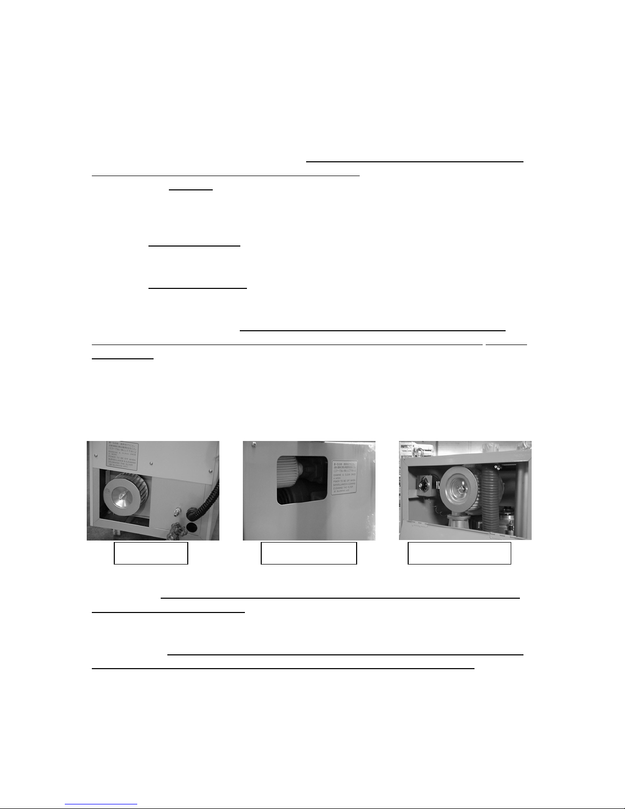
Regeneration Filter: In all models, the regeneration filter is mounted directly on
the regeneration blower. This filter cleans the air flowing over the regeneration
heater and through the desiccant rotor.
sure the dryer is shut off and the blowers stopped.
On the
hole at the bottom. This filter, since it is low to the ground, gets very dirty very
fast! Remove this filter by unscrewing the hold down wing nut and removing the
nut and washer.
On
square hole at the top of the rear panel. The filter simply unscrews from the
blower and removed through the hole.
On DMZ-170 and 240 models, the filter is accessed through a flip-down
panel at the top rear of the dryer, Remove the two wing screws holding the panel
shut. With the door panel open, remove the wing nut and washer holding the
regeneration filter in place.
inside out. The filter should be changed every 6 months or sooner under servere
conditions. The regeneration exhaust should blow as hard with a clean filter
as it does with no filter. If you blow out the filter and the airflow from the
regeneration exhaust diminishes considerable when you re-install the filter,
install a new filter! In all cases, installation is in reverse order of removal.
Process Filter: On DMZ 40-240, the process filter is located on the back middle
of the dryer.
both blowers have stopped. This is important to keep foreign matter out of the
desiccant rotor. Remove the knurled knob and washer holding the round cover in
place. With the cover off, remove the wing nut and rubber washer holding the
filter in place.
should be changed every 6 months or sooner under severe conditions. If the
filter has been blown out and the inside does not look white anymore,
install a new filter! Replace the filter in the reverse order of removal, being sure
to install the rubber washer rubber side against the filter.
DMZ-40 DMZ-80 / 120 DMZ-170 / 240
DMZ-40 model, this filter is accessed on the back panel, through a
DMZ-80 and 120 models, the regeneration filter is accessed through a
Using compressed air, blow out the filter from the
REGENERATION FILTER LOCATIONS
To clean or change this filter, first shut down the dryer and be sure
Using compressed air, blow out the filter from the inside. The filter
To clean or change this filter, first, make
5
Page 6
Regeneration Temperature: The regeneration temperature is factory set at
446°F (230°C). This is the optimum temperature for removing moisture from the
desiccant rotor during the regeneration cycle. This temperature can be checked
by pressing the “PV” button on the face of the controller until the L.E.D. indicator
is under the word “REGEN” and 446° reads in the “PV” window. A regeneration
temperature of less that 410°F (210°C) is indicative of a problem with the
regeneration system.
Process temperature: Simply stated, if the process, or drying temperature in the
“PV” window is more than a few degrees off from the temperature entered in the
“SV” window, after an hour of running, there is probably a problem on the drying
side of the DMZ. Remember though, the minimum guaranteed temperature for a
DMZ is 130°F (54°C), so it may not go lower than that.
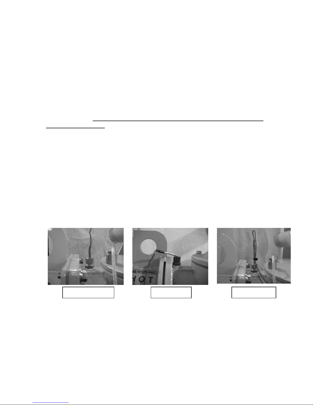
Thermocouple on Drying Hopper: The thermocouple on the drying hopper
should be checked for damage and proper adjustment regularly. The end tip
should be dead center in the middle of the heater box tube. This should be
factory set, however check to make sure the nut is tight and the thermocouple
can’t move up or down. If the thermocouple is severely bent or broken, replace it!
Inside the thermocouple there are two very small and fragile wires that can easily
be damaged if the thermocouple is smashed or bent. If these wires are damaged,
or the thermocouple is misadjusted, the temperature controller may inaccurately
sense the hopper temperature. This can cause poor drying, or in the worst case
a material meltdown in the hopper.
THERMOCOUPLE ADJUSTMENT
DAMAGED CORRECTMISADJUSTED
Drying Hoses: The drying hoses, or the orange Hoses, should be checked
regularly for cuts, abrasions, kinks or other damage that would impede maximum
air flow. If a hose is cut, outside air can be brought into the machine thus
reducing the ability of the dryer to create a dry material, Likewise, is a hose is
kinked or crushed, airflow over the resin pellets may be impeded, slowing the
time it takes to dry the material. Damaged hoses should be replaced
immediately.
6
Page 7
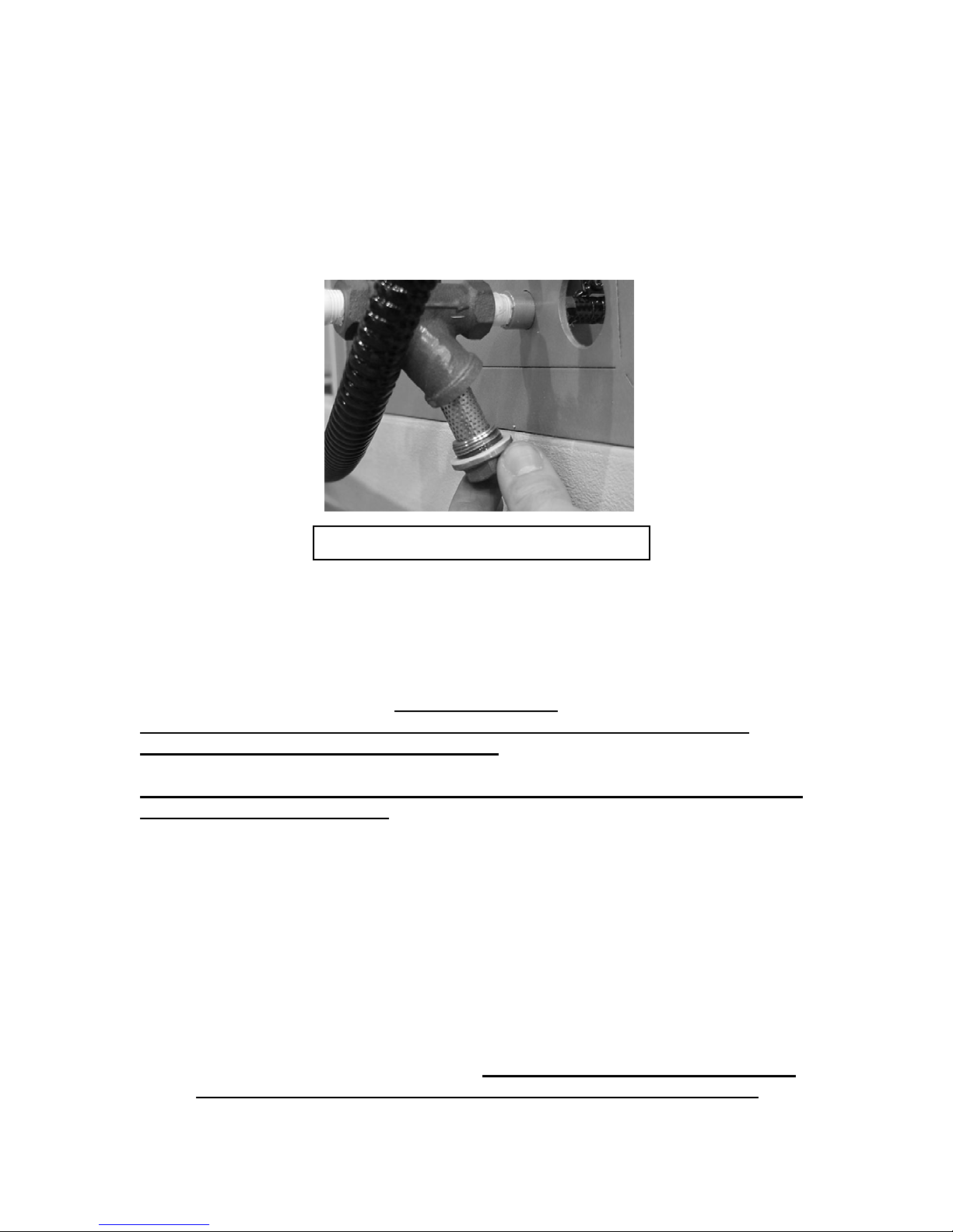
Aftercooler Water Supply: Check to make sure that water is flowing to the
aftercooler. Make sure the valve is open and clean the strainer at least twice a
year. To clean the strainer, shut off the water valve, and remove the strainer nut
at the bottom of the strainer. Remove the strainer and clean it of debris and any
corrosion. Replace the strainer and tighten the nut.
STRAINER MAINTENANCE
REMOVE AND CLEAN STRAINER
Magnetic Heater Contactors: The heater contactors should be checked on a
monthly basis to ensure proper operation. Typically there are two Heater
contactors, although some high heat models may have three or four. There are
two ways to check a contactor. In either case, you will need a Multi-Meter to
properly check operation.
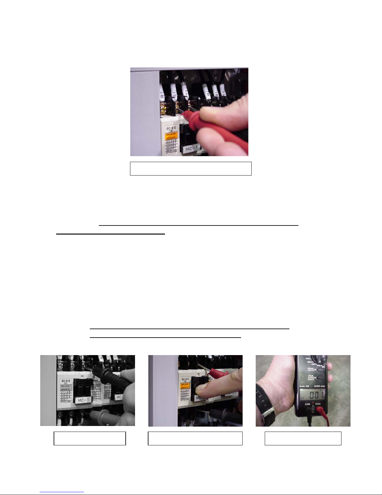
VOLTAGE CHECK:
Electrical maintenance should only be performed by individuals with
proper electrical knowledge and training
The first check, the voltage check, can be done with the machine running.
Always use extreme caution when working on and around the high voltage
inside the electrical cabinet.
1) Set the Multi-meter to the proper AC voltage setting that corresponds to
the voltage rating of your machine.
2) Confirm that the proper voltage is being supplied to the “line” side of the
contactor by checking the “line” side leads horizontally, between each pair
of “line “ leads, (L1&L2, L1&L3 and L2&L3). This voltage should be the
same as the plant voltage. (See fig. 1)
3) Next, repeat this process on the “load” side leads of the contactor. Keep
in mind you will only get a voltage reading when the contactor is active,
(contacts pulled in). The voltage should be the same across the “load”
side (T1&T2, T1&T3 and T2&T3) as it is on the “line” side. (See fig 2) If
one or more of the leads has substantially lower or no voltage, this is
indicative of a defective contactor. Be sure to shut off the power at the
breaker or buildings disconnect before replacing the contactor.
7
Page 8
Magnetic Heater Contactors Cont.
CHECKING INPUT VOLTAGE
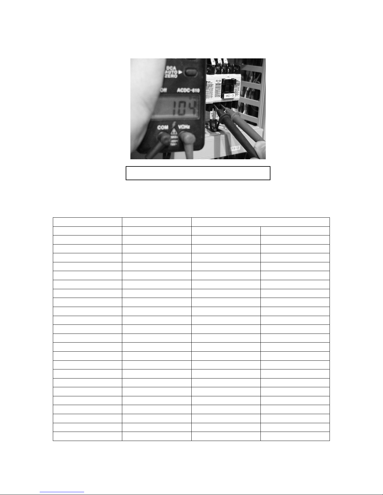
RESISTANCE CHECK:
The second check, the resistance check must be done with the power to the
machine off. Be sure to shut off the power at the breaker or buildings
disconnect before proceeding.
1) Set the Multi-meter to the Ohms setting. The Ohms setting may be
labeled Ω. Once again, be sure the power to the dryer if off.
2) Place one of the meter probes on a “line” side terminal and the other to
the corresponding “load” side terminal, for example L1&T1, L2&T2,
L3&T3. (See fig 1.)
3) With the probes in place, manually press the actuator on the center
face of the contactor until the contactor closes and a reading appears
on the meter. Repeat across all three phases. (See fig. 2.)
4) The measured value should be between 0.00-0.03 Ohms. A greater
value is indicative of a defective contactor, which should be replaced.
Be sure to shut off the power at the breaker or buildings
disconnect before replacing the contactor.
METER PROBES CONTACTOR CLOSED CORRECT RANGE
8
Page 9

Magnetic Blower Contactors: Follow the same directions as the magnetic
heater contactors.
Regeneration Heater: The regeneration heater should be checked for proper
resistance regularly to confirm it is working properly and ensure proper desiccant
rotor operation. Like any mechanical part, heaters wear over out over time. Worn
or defective magnetic contactors can also damage a heater. Checking heaters,
like checking contactor resistance, is done with the power off. You will need a
Multi-meter to complete this test. Be sure to shut off the power at the breaker
or buildings disconnect before proceeding.
1) Set the Multi-meter to the Ohms setting. The Ohms setting may be
labeled Ω. Once again, be sure the power to the dryer if off.
2) Measure Ohms at the load side of the contactor (heater wire terminals)
between all three leads in each combination (T1&T2, T1&T3 and
T2&T3). Every combination should have the same Ohm reading, give
or take 3 or 4 Ohms. If the heater is aging equally across all three
elements, the Ohms values should be similar.
3) To calculate exact values, Check the chart on page 10, or use the
following formula to calculate the exact values:
R = 2xVxV
W
R = Resistance
V = Voltage
W = Watts
Example: 2x230x230
1.5kw (1500)*
* Be sure to change Kilo value to its actual value. (2.4kw =2400 w)
In this example, resistance is 70.5 Ohms
So, in this case, you should have 70.5 Ohms across all three heater lines.
Process Heater: Follow the same directions as the regeneration heater.
9
Page 10
Heaters cont.
EXAMPLE OF HEATER RESISTANCE
HOPPER HEATER RESISTANCE CHART (ohms)
HOPPER HEATER
230V 460V
HD-15R 1.5 kW 70.5 Ω 282.1 Ω
HD-25R 2.4 kW 44.1 Ω 176.3 Ω
HD-50R 2.4 kW 44.1 Ω 176.3 Ω
HD-75R 3.3 kW 32.1 Ω 128.2 Ω
HD-100R 3.3 kW 32.1 Ω 128.2 Ω
HD-150R 4.0 kW 26.5 Ω 105.8 Ω
HD-200R 4.0 kW 26.5 Ω 105.8 Ω
HD-250R 3.0 kW 35.3 Ω 141.1 Ω
Dual Element 3.0 kW 35.3 Ω 141.1 Ω
HD-300R 3.0 kW 35.3 Ω 141.1 Ω
Dual Element 3.0 kW 35.3 Ω 141.1 Ω
HD-15RDH 2.1 kW 50.4 Ω 201.5 Ω
HD-25RDH 4.0 kW 26.5 Ω 105.8 Ω
HD-50RDH 4.0 kW 26.5 Ω 105.8 Ω
HD-75RDH 6.0 kW 17.6 Ω 70.5 Ω
HD-100RDH 6.0 kW 17.6 Ω 70.5 Ω
HD-150RDH 3.9 kW 26.6 Ω 108.5 Ω
Dual Element 3.9 kW 26.6 Ω 108.5 Ω
HD-200RDH 3.9 kW 26.6 Ω 108.5 Ω
Dual Element 3.9 kW 26.6 Ω 108.5 Ω
HD-250RDH 6.2 kW 17.1 Ω 68.3 Ω
Dual Element 6.2 kW 17.1 Ω 68.3 Ω
HD-300RDH 6.2 kW 17.1 Ω 68.3 Ω
Dual Element 6.2 kW 17.1 Ω 68.3 Ω
10
Page 11

A
Desiccant Rotor: The desiccant rotor should be checked for proper operation on
a regular basis.
DMZ-40 MODELS
The desiccant rotor indexes 1 ¼” every 60 seconds. This is controlled by a
circuit board located inside the electrical panel. Adjusting the two small
potentiometers, labeled VR-1 and VR-2 located on the circuit board
labeled MTR-5 can control the time and distance. VR-1 controls the off
time between indexes. VR-2 controls the on time the rotor moves at each
index. If necessary, each can be adjusted with a very small turn of the
appropriate switch. On VR-1, clockwise will increase the time between
indexes; counterclockwise will decrease the time between indexes.
On VR-2, clockwise will increase the distance of travel at each index;
counterclockwise will decrease the distance of travel at each index.
The index time and distance should only be set to the factory setting
of 1 ¼” every 60 seconds. Altering these settings will compromise
proper material drying, as well as cause un-necessary wear to the
desiccant rotor components.
VR-2 VR-1
DJUSTED TO 1 ¼”MTR-5 CIRCUIT BOARD
DMZ-80-240 MODELS
The desiccant rotor on the DMZ-80-240 models, unlike the DMZ-40, does
not index, but instead turns at three revolutions per hour by means of a
geared motor. This motor is geared at 1 to 32000 and is controlled by
either a magnetic contactor or relay located inside the electrical panel. No
adjusted is necessary or even possible with this motor. Simply, confirm
that the rotor is turning properly.
11
Page 12

Desiccant Rotor cont.
Check to make sure that the tension springs on the desiccant rotor top
cover are tensioned properly. Improperly tensioned springs can result in
premature rotor wear and can cause air leaks, which in turn can effect
dryer performance.
On DMZ-40 to 120 models, the distance between the washers should
be 27mm. On DMZ –170 and 240 models, the distance between the
washer should be 23mm.
Check this spacing and adjust as necessary by tightening or loosening the
nut on top of the spring. These springs are factory set and should not
need to be adjusted under normal circumstances, however is good to
check the occasionally.
ROTOR SPRING TENSION
27mm
23mm
DMZ-40-120
DMZ-170-240
Cabinet Interior: Keep the interior of the DMZ as well as the electrical panel
clean and free of dust. Remove a side panel and using compressed air, blow out
dust, fines, pellets and other foreign matter from inside of the DMZ
1) Pay particular attention to the blowers and around the desiccant rotor.
The backs of the blowers tend to gather lots of dirt, impeding the
cooling abilities of the cooling fan. This can result in higher amp draw
and shortened motor life.
2) Keep the exterior of the desiccant rotor as clean as possible. The
desiccant rotor rides on surfaces coated with Teflon®, which are
subject to wear. Keeping the inside of the cabinet clean will ensure
long life of interior components.
3) Blow out the electrical panel to remove dust and other contaminants
that could get inside the magnetic contactors and other components.
12
Page 13

ALARMS
The following is a list of alarms that may be encountered on the DMZ controller.
There are two types of controllers used on Matsui DMZ Dryers. The MR-1200
was used from introduction until about 1998 at which time it was replaced by the
more advanced MR-2200. Both controllers basically work the same way,
however the newer MR-2200 is a little more sophisticated in that it has more
alarm functions. We’ll cover the alarms common to both controllers first, and
those, which are specific to each Controller, last.
CONTROLLERS
MR-1200 CONTROLLER MR-2200 CONTROLLER
CONTROLLER ALARM PANELS
MR-1200 ALARMS MR-2200 ALARMS
13
Page 14

Reverse: This alarm, common to both controllers, indicates a problem with the
power supply coming into the dryer. All Matsui equipment is phased A-B-C. (RRed, S-White, T-Black). If this alarm lights, look for and correct the following:
Incoming power phase is reversed. Change incoming power to correct
¾
A-B-C phase
¾
Single Phase. This means that one of the three phases is out, either by
loose connection at the dryer, or at the disconnect feeding the DMZ.
Check all electrical connections.
¾ Occasionally, there is a problem with incoming plant voltage, supplied
by the Power Company. If you are certain the phases are correct,
contact your power supplier and have them check your plant voltage.
¾ If all of the above items check out, it is possible there is an internal
problem with the controller. Contact Matsui Service in the event all the
above checks out.
Overload: The overload alarm on the MR-1200, or the drying or regeneration
overload alarms on the MR-2200 are tripped by the thermal relay, which is
located on the bottom of each of the drying and regeneration blower magnetic
contactors. When the thermal relay or OCR as we’ll refer to it, sensing high
amperage draw from either blower, trips and shuts down the blower to prevent
the blower from being damaged. Coincidentally, the corresponding overload
alarm will light on the Controller.
On models equipped with MR-1200 controllers, if the OCR senses high
amperage, the OCR will trip, the alarm will sound, the blowers and heaters will
shut off, but power to the panel will stay on.
On models equipped with MR-2200 Controllers, the dryer is equipped with a
shunt type circuit breaker which, when an overload has been sensed, will not
only sound the alarm turn off the blowers and heaters, it will trip the circuit
breaker stopping power to the entire machine.
If this alarm lights, look for and correct the following:
¾ The OCR is not set to the correct amperage setting. Refer to the motor
nameplate for the correct maximum ampere setting for the voltage of
the blower. Remember to set the OCR about 10% higher then the
maximum ampere rating of the blower.
¾ Blower plugged or jammed. The blower may be jammed or plugged
with a foreign object sucked in from the outside. If the filter has not
been put on properly, or the filter removed with the blowers running,
material could have been sucked in.
Disconnect the power and
remove the back cover from the blower. Checks to make sure the
blower turns freely and remove any obstruction.
¾
Check wiring. Check to make sure there are no loose, shorted or
disconnected wires in the blower junction boxes.
Disconnect the
power and repair any evident wiring problems.
Contact Matsui Service in the event that all of the above checks out.
14
Page 15

Filter: The filter alarm is an optional alarm that works only if the optional filter
clog alarm has been installed. If the filter clog alarm has been installed, and the
alarm is sounding, check for the following:
Filters are dirty. In the event the filter Alarm sounds, the primary cause
¾
is that the alarm is just doing its job, and alerting of a clogged filter. If
the filter alarm sounds it usually means the filters are beyond cleaning
with compressed air. Change the filters with the appropriate filter
¾
Sensors misadjusted. Occasionally, even when new filters have been
installed, the filter alarm will still sound. In this case, it is possible to
adjust the sensitivity of the filter clog sensors. Open the electrical panel
door and look for the sensors on the left side wall. There is a small
adjustment screw located on each sensor. Turning the screw counterclockwise decreases sensitivity, turning the screw clockwise increases
sensitivity. With new filters installed, decrease the sensitivity until the
alarm just turns off. Now the sensors should be adjusted properly.
On MR-1200 models, the alarm will clear after the problem has been corrected.
On MR-2200 models, press the “Alarm Reset” button after the problem has been
corrected.
Sensor: This alarm will sound if one of the thermocouples becomes
disconnected or damaged. If this alarm sounds, machine operation will stop and
the letters “FFFF” will appear in the “PV” window on the controller.
¾ Check for thermocouple damage. Either the process thermocouple (on
the hopper heater tank) or the regeneration thermocouple has become
damaged and needs to be replaced.
¾ Check for loose wiring. Thermocouple wires inside the dryer’s electrical
panel may have come loose. Check the terminals at the bottom of the
controller and elsewhere in the panel.
Shut down the power to the dryer and correct the problem. Once the problem is
corrected the alarm will clear.
H’EST (Highest Alarm): This alarm sounds when the drying air temperature
goes higher than the set process temp plus the set Highest temp. For example, if
you have a process set temp of 200° F and a Highest setting of 40°F, if, for
whatever reason the actual process temp rises past 240°F, the highest alarm will
sound. As the temp drops back down below 240°F the alarm will turn itself off.
This alarm is to alert the operator of a potential problem before it becomes a
problem. The setting value for the highest Alarm is set using the “SV” button.
There are several reasons for the highest Alarm to sound, check for the
following:
Cont.
15
Page 16

H’EST (Highest Alarm) cont.
¾ Initial warm-up. Occasionally, and very rarely, this alarm will sound on
the initial start-up of the dryer, especially if the machine is cold and the
hopper is empty. This however is very rare and should not happen
under normal circumstances.
¾ Insufficient air flow. Filters have become dirty impeding airflow over the
process or regeneration Heaters. Clean or if needed, change the
filters. Check to make sure the blowers are turning properly and are
not plugged with foreign matter that would impede airflow.
¾ Wrong or to high incoming voltage. If a 230-volt machine is being run
on 460 volts, or the incoming plant voltage is to high, this may cause
the heaters to overshoot the set value and cause a highest Alarm. If
this happens, correcting the voltage problem will correct the alarm.
¾ Defective or inoperative blower contactor. Check to make sure that the
blower magnetic contactors inside the electrical panel are activated,
and that there is proper voltage going through them. (See pg. 9).
Replace if necessary.
¾ Defective Heater Contactor. Check to make sure that the heater
magnetic contactor is not stuck in the “on” position. The heater
contactor should only be activated when the appropriate “heater” lights,
either “Dry” or “Regen” are lit on the Controller. If neither the “DRY” or
“REGEN” heater lights are lit on the Controller, and one of the heater
contactors is pulled in, this may signal a defective contactor. Check to
make sure there is no voltage (100 V) at the coil of the pulled in
contactor. If no voltage is present, the Contactor is defective. If voltage
is present, contact the Matsui Service Dept. for help.
Once the problem is corrected, the ‘H’EST” alarm should clear itself. If the H’EST
alarm fails to clear itself, shut off the dryer and turn off the incoming power, either
at the plant disconnect, or the dryer circuit breaker, for 15 seconds. Restoring
power should then clear the alarm.
L’EST (Lowest Alarm): This alarm sounds when the drying air temperature goes
lower than the set process temp minus the set lowest temp. For example, if you
have a process set temp of 200° F and a lowest setting of 40°F, if, for whatever
reason the actual process temp drops below 160°F, the lowest alarm will sound.
As the temp rises back up to 200°F the alarm will turn itself off. This alarm is to
alert the operator of a potential problem before it becomes a problem. The setting
value for the lowest Alarm is set using the “SV” button. There are several
reasons for the lowest Alarm to sound, check for the following:
Cont.
16
Page 17

L’EST (Lowest Alarm) cont.
¾ Defective heater contactor. Check to make sure that the heater
magnetic contactor is not stuck in the “off” position. The Heater
contactor should be activated when the appropriate “HEATER” lights,
either “DRY” or “REGEN” are lit on the Controller. If either the “DRY” or
“REGEN” heater lights are lit on the controller, and the corresponding
heater contactor is not pulled in, this may signal a defective contactor.
Check to make sure there is voltage (100 V) at the coil of the suspect
contactor. If voltage is present, and the contactor will not pull in, the
contactor is defective. If voltage is not present, contact the Matsui
Service Dept. for help.
¾ Defective Heater. If a defective magnetic contactor is broken for two
long, eventually, the corresponding heater will burn out. In this case,
even if the magnetic contactor is replaced, the heater will still not come
up to temp. Replacing the heater is the only remedy in this case. See
pg. 9 or directions for checking a heater.
Once the problem is corrected, the ‘L’EST” alarm should clear itself. If the ‘L’EST
alarm fails to clear itself, shut off the dryer and turn off the incoming power, either
at the plant disconnect, or the dryer Circuit Breaker, for 15 seconds. Restoring
power should then clear the alarm.
Overheat: The overheat alarm on the MR-1200, or the drying or regeneration
overheat alarms on the MR-2200 are tripped by an overheat sensor, which are
located on the to of each of the drying and regeneration Heater Tanks. When the
overheat sensor senses heat higher than the set heat value, the overheat sensor
trips and shut down the dryer. There are two types of overheat sensors used on
DMZ Dryers: An earlier fixed version generally used with the MR-1200 equipped
dryers and a newer adjustable style generally used with the MR-2200 equipped
dryers. It is possible to have the older, non-adjustable style with an MR-2200
controller and vice-versa. The fixed style is designed to trip when the heater temp
reaches 491°F (255°C). The newer adjustable style is generally set at 40°F over
the process set point.
On models equipped with MR-1200 controllers, if the overheat sensor senses
high heat, the sensor will trip, the alarm will sound and the blowers and heaters
will shut off, but power to the panel will stay on.
On models equipped with MR-2200 Controllers, the dryer is equipped with a
shunt type circuit breaker which, when an overheat has been sensed, will not
only sound the alarm turn off the blowers and heaters, it will trip the circuit
breaker stopping power to the entire machine.
If this alarm lights, look for and correct the following:
Cont.
17
Page 18

Overheat cont.
¾ Insufficient air flow. Filters have become dirty impeding airflow over the
process or regeneration heaters. Clean or if needed, change the filters.
Check to make sure the blowers are turning properly and are not
plugged with foreign matter that would impede airflow.
¾ Defective or inoperative Blower Contactor. Check to make sure that
the blower magnetic contactors inside the electrical panel are
activated, and that there is proper voltage going through them. (See
pg. 9). Replace if necessary.
¾ Defective Heater Contactor. Check to make sure that the heater
magnetic contactor is not stuck in the “on” position. The heater
contactor should only be activated when the appropriate “HEATER”
lights, either “DRY” or “REGEN” are lit on the Controller. If neither the
“DRY” or “REGEN” heater lights are lit on the controller, and one of the
heater contactors is pulled in, this may signal a defective contactor.
Check to make sure there is no voltage (100 V) at the coil of the pulled
in contactor. If no voltage is present, the contactor is defective. If
voltage is present, contact the Matsui Service Dept. for help.
¾ Overheat Sensor adjustment. On models with adjustable overheat
sensors on the drying hopper, be sure the sensor is adjusted high
enough for the process temperature that is inputted in the controller.
For example, if the drying set point is 250°F and the overheat sensor is
adjusted to 240°F, the overheat alarm will trip. Adjust the overheat
sensor to about 20-30°F above the drying set temperature.
¾ Defective Overheat Sensor. Occasionally, an overheat sensor,
especially the non-adjustable type on the drying hopper, will go bad
with age. While this is rare, the only remedy is to replace the overheat
sensor. This sensor is located inside the top of the hopper heater tank.
To change the sensor, remove the 4 bolts attaching the hose manifold
to the top of the heater tank and remove the manifold. Inside you will
see the sensor, with two wires, held down by two small screws.
Once the problem is corrected, turn off the breaker, if it hasn’t already tripped,
then turn the breaker back on to clear the alarm.
Heater (MR-2200 only): This alarm activates if a defect is sensed in either the
process or regeneration heaters. If this alarm sounds, troubleshoot the heater
circuit and repair the problem. Once the repair is made, repower the dryer and
the alarm should be cleared.
Material Low: This is an optional alarm that will only work if the low level alarm
kit is installed. This will alarm if material in the hopper drops below the paddle of
the level switch.
Dew Point: This alarm is not used and will not light.
18
Page 19

TROUBLESHOOTING
Checkpoints and remedies are described on the following pages. Refer to this
point before seeking repair advice from the Matsui Service Department
WARNING:
Working around electricity can be extremely dangerous.
Electrical service and troubleshooting should only be performed
by those with knowledge of electrical circuits and proper
training in electrical repair. Anyone unfamiliar with electrical
repair should not attempt these repairs.
CAUTION
Before doing any inspections, set the “RUN-STOP” switch to the “STOP”
position and allow the dryer to complete it’s cool down cycle before
proceeding. Always turn off power at the DMZ circuit breaker or plant
disconnect before proceeding with repairs. As always use extreme caution
when working on or around live electrical components to avoid injury or
death.
TROUBLESHOOTING
ITEM: DESCRIPTION: PAGE
Blower Blower does not turn on 20
Blower Overload Relays Trip 20
Blower air flow is low 21
Drying Temperature Drying temperature changes rapidly 21
Drying temperature highest / lowest alarm 21
Drying temperature does not go up / down 22
Inadequate drying Moisture content of resin doesn’t go down 22
Temperature Controller PV or SV indicator does not display 22
19
Page 20

TROUBLESHOOTING
Blower does not turn on:
1) Is the plant disconnect and DMZ circuit breaker on?
Yes No –Turn on disconnect or breaker
▼
2) Do the temperature controller PV and SV indicators light?
Yes No –Check and replace fuse, check power connections
▼
3) When the “RUN” switch is pushed, do the blower indicator lights on the
temperature controller light?
Yes No –Check to make sure no value is entered in the “TIMER”
mode.
4) When the “RUN” switch is pushed, do the blower contactors activate?
Yes No –Check the contactor coil for 100v. If present, replace
magnetic contactor. If no voltage, contact Matsui Service
▼
5) Is the overload relay tripped?
No Yes –There should be an alarm sounding, but just in case
Its not, reset the overload
▼
6) Is there line voltage at the overload relay when the contactor is activated?
Yes No –Follow the Maintenance Instructions and check the
contactor. If contactor checks out, replace overload relay.
▼
7) Is there line voltage at the blower?
Yes No – Check for loose or shorted wires.
▼
Contact Matsui Service.
Blower overload relay trips:
1) Is the overload relay set to the proper amp setting?
Yes No – Check corresponding blower for proper amp setting
and reset.
▼
2) Do the blowers turn freely?
Yes No – Check for and clear any obstructions inside the blower.
▼
3) Is the magnetic contactor working properly?
Yes No – Replace contactor and reset overload relay
▼
Contact Matsui Service
20
Page 21

TROUBLESHOOTING
Blower airflow is low:
1) Have new filters been installed?
Yes No – Install new filters.
▼
2) Are the hoses, both inside and outside of the dryer in good condition and free
from kinks, holes and crushing?
Yes No – Replace hoses with the proper type hose.
▼
3) Are the blowers free from clogging?
Yes No – Remove intake and exhaust ports from blower and
clear any plug or clogging
Drying temperature changes rapidly:
1) Have new filters been installed?
Yes No – Install new filters
▼
2) Is the thermocouple in good condition and in the right position?
Yes No – Replace or adjust the thermocouple
▼
3) Is the polarity of the thermocouple correct?
Yes No – Correct thermocouple polarity
▼
Drying temperature highest or lowest alarm:
1) Is dryer through initial warm-up?
Yes No – Allow dryer to complete its warm-up cycle and allow
the temperature to stabilize.
▼
2) Have new filters been installed?
Yes No – Install new filters
▼
3) Is the incoming (plant) voltage correct for the unit?
Yes No – Correct the voltage problem
▼
4) Are the blowers and blower contactors working properly?
Yes No- Correct the problem with a new contactor or
Repair the blower problem.
▼
5) Is the thermocouple in good condition and in the right position?
Yes No – Replace or adjust the thermocouple
21
Page 22

TROUBLESHOOTING
Drying temperature does not go up or down:
1) Are the heater contactors activated when the controller is calling for heat, and
off when it’s not?
Yes No – Check voltage at the coil of the contactor as well as the
output of the controller for proper operation. Replace
contactor or service controller as necessary.
▼
2) Is the SENSOR alarm on the controller flashing?
No Yes – Check for proper thermocouple wiring or replace
defective thermocouple.
▼
3) Are the hoses, both inside and outside of the dryer in good condition and free
from kinks, holes or crushing?
Yes No – Replace hoses with proper type hoses.
Moisture content of resin does not go down:
1) Is the process temperature set to the correct setting?
Yes No – Change to minimum of 130°F (55° C)
▼
2) Have new filters been installed?
Yes No – Install new filters
▼
3) Is there water flowing to the aftercooler
Yes No – Make sure the strainer is clean and the water is on.
▼
4) Are the hoses, both inside and outside of the dryer in good condition and free
from kinks, holes and crushing?
Yes No – Replace hoses with proper type hoses.
▼
5) Are the heaters and magnetic contactors working properly?
Yes No- inspect and replace following directions in Maintenance
section.
▼
PV or SV indicator does not display?
1) Is the power disconnect and the DMZ circuit breaker on?
Yes No- Turn on the power supply
▼
2) Check the glass fuse (F-1) inside the control panel and replace if necessary.
22
Page 23

FREQUENTLY ASKED SERVICE QUESTIONS
Following are a few of the most common service problems encountered by our
Service Personnel, and checkpoints and remedies for each problem.
“ My Dew Point is high and I’ve got wet plastic. What’s wrong?”
Here are the usual culprits;
1) Is the process temperature set above 130°F (55°)?
Yes No –Change to at least 130° F (55° C).
▼
2) Is the regeneration temperature of 446°F (230° C)
Yes No –Follow Maintenance Description and check
regeneration heater and contactor, replace as needed.
▼
3) Is the regeneration exhaust strong? As strong as when the filter’s off?
Yes No – Change the regeneration filter.
▼
4) Is there water flowing to the aftercooler?
Yes No –Clean the strainer and turn the water on.
▼
5) Is the desiccant rotor turning or indexing correctly?
Yes No –Adjust timing Card (DMZ-40) or check gear motor
and contactor for proper operation and repair as needed.
▼
6) Are the drying hoses free from leaks, cuts, and wear or crush damage?
Yes No –Replace the damaged hoses. Patching with duct tape
doesn’t count! Check the hoses inside the dryer also.
▼
7) Is the drying hopper thermocouple in good shape and properly adjusted?
Yes No –If it’s bent or damaged replace it! If it’s out of adjustment
adjust it per the directions in the Maintenance section
▼
8) Has the process filter been changed recently?
Yes No – If it’s blown out and still seems dirty, when in doubt,
▼
9) Is the process temperature reaching set point?
Yes No –Follow Maintenance Description and check process
▼
10) Is the diffuser cone inside the hopper properly installed and in good order?
Yes No –Install or replace the diffuser cone
install a new filter!
heater and contactor, replace as needed.
23
Page 24

FREQUENTLY ASKED SERVICE QUESTIONS
“I just changed my Regeneration Contactor and filter. Why is there smoke
coming from the Regeneration exhaust port?”
Here’s why:
The main purpose of the regeneration system is to burn moisture and
contaminants, like gases and waxes given off from the drying plastic pellets, from
the desiccant rotor. To do this properly, high heat (446°F / 230°C), proper rotor
turning or indexing and good airflow are required. If either the heat, rotor turning
or airflow is compromised, like when a contactor goes bad, or a filter is clogged,
the result will be a build-up of contaminants inside the desiccant rotor. Once
correct heat, indexing and airflow are restored, the contaminants are heated and
blown from the rotor, occasionally resulting in smoke from the regeneration
exhaust. Generally, this smoking will last 1 to 3 hours, and other than being a
nuisance, poses no great problems.
“I’m trying to dry material at 100°F, but my dryer won’t go below 128°F.
Why?”
Here’s why:
The minimum guaranteed drying temperature of DMZ dryers is 130°F (55°C).
The reason for this is, the regeneration cycle heats the desiccant rotor with 446°F
(230°C) heat, to burn off moisture and contaminants. After the Desiccant Rotor
passes through the regeneration cycle, it turns through a cool down zone. This
zone cools down the desiccant rotor to a temperature that will optimize its
absorption of moisture in the process cycle. After going through the cool down
zone, the desiccant rotor is still very warm, hence any air passing through it as it
moves through the process air absorption zone, will pick up this surplus heat
and, even if the process heater isn’t on, the air will still get heated. Although
130°F is the minimum guaranteed drying temperature, occasionally a dryer will
be able to get lower than that temp, even as low as 120°F (48°C), but this is
unusual and depends on ambient temperature and the temperature of the air
returning from the drying hopper.
“Why is there black dust under the heater contactors inside the electrical
panel?”
Here’s why:
The magnetic contactors have carbon contacts that wear with each on / off cycle,
causing the dust. A lot of black dust is a sure sign that those contactors are
probably old and ready for a change. Follow the Maintenance Directions and
check the contactors. Blow the dust out of the cabinet with compressed air.
24
Page 25

FREQUENTLY ASKED SERVICE QUESTIONS
“The process filter on my DMZ looks just like the air cleaner in my wife’s
car. Why do I need to buy Matsui’s filters?”
Here’s why:
Although they may look the same, there’s a vast difference between a car’s air
cleaner and a Matsui filter. First off, the filter media in the Matsui filter is
considerably finer, designed to take out even the minutest particle of dust. This is
necessary to ensure long life of the desiccant rotor, as well as the Teflon®
coated rotor housing. Secondly, the gasket material is designed not only to help
seal dust from the rotor, but it is a non-porous material designed for easy,
complete cleaning to prevent cross-contamination during material changes.
Lastly, it is supplies with a rubber washer to completely seal the filter. That’s why
it’s important to use the correct Matsui filter and washer for each DMZ dryer.
“I’ve had my DMZ for about three years now, I’ll need to change my
desiccant soon, right?
Wrong. Here’s why:
Unlike bed type dryers, where the desiccant beads need to be changed
frequently, Matsui’s unique rotor design, under normal circumstances, and with
regular maintenance, will last for well over ten years without replacement. Due to
the constant regeneration cycle of the Matsui DMZ, the rotor absorbs and dries
uniformly, resulting in a lower, stable dew point and increased desiccant life.
“I’ve got a Matsui installed dew point meter on my DMZ. Why is it installed
on the supply air to the hopper, rather than the return?”
Here’s why:
A dew point meter is an excellent tool for monitoring the performance of a dryer.
If the DMZ is properly maintained and serviced, a dew point of -40° F or lower
can be maintained. Matsui installs their dew point meter on the supply side air, to
monitor the drying ability of the DMZ. If a dew point meter is installed in the return
air, each time new material is added, the dew point could fluctuated with the
influx of wet air, thus giving a false reading on the moisture in the material. By
checking the dew point on the supply side, it is easier to tell if there is a problem
with the dryer. If the air going to the hopper is as dry as possible, then drying of
the plastic resin pellets should be complete. If a dew point on the supply side
rises, it is evidence of a service problem with the dryer that needs to be
addressed.
25
Page 26

COMMON SPARE PARTS
PART: MODEL: PART NUMBER:
REGENERATION FILTER DMZ 40 MXF-267-75P A10978
REGENERATION FILTER DMZ 80-120 MXF-204P AA0516
REGENERATION FILTER DMZ 170-240 847-AS100 A04749
PROCESS FILTER DMZ 40-120 MXF-16-SP A40514
PROCESS FILTER DMZ 170 847-AS250P A16401
PROCESS FILTER DMZ 240 847-350A A30920
BLOWER CONTACTOR SC-03 AA0307
HEATER CONTACTOR SC-0Y AA0315
HEATER CONTACTOR SC-4-1 AA0313
HEATER CONTACTOR SC-1-N AA0311
THERMOCOUPLE-HOPPER K3.2X100X1000 AA1524
THERMOCOUPLE-REGENERATION K3.2X100X4000 AA1527
FILTER CAN GASKET DMZ 40~120 AA0593
FILTER CAN GASKET DMZ 170 / 240 AA0594
REGENERATION HEATER DMZ-40 1.5 kW 230 VOLT AA0816
REGENERATION HEATER DMZ-40 1.5 kW 460 VOLT AA0817
REGENERATION HEATER DMZ-80 2.4 kW 230 VOLT AA0826
REGENERATION HEATER DMZ-80 2.4 kW 460 VOLT AA0827
REGENERATION HEATER DMZ-120 3.0 kW 230 VOLT AA0836
REGENERATION HEATER DMZ-120 3.0 kW 460 VOLT AA0838
REGENERATION HEATER DMZ-170 5.8 kW 230 VOLT AA0848
REGENERATION HEATER DMZ-170 5.8 kW 460 VOLT AA0850
REGENERATION HEATER DMZ-240 9.0 kW 230 VOLT AA0854
REGENERATION HEATER DMZ-240 9.0 kW 460 VOLT AA0857
HOPPER HEATER 1.5 kW 230 VOLT AA0816
HOPPER HEATER 1.5 kW 460 VOLT AA0817
HOPPER HEATER 2.1 kW 230 VOLT AA0788
HOPPER HEATER 2.1 kW 460 VOLT AA0789
HOPPER HEATER 2.4 kW 230 VOLT AA0791
HOPPER HEATER 2.4 kW 460 VOLT AA0792
HOPPER HEATER 3.3 kW 230 VOLT AA0793
HOPPER HEATER 3.3 kW 460 VOLT AA0794
HOPPER HEATER (HD-25 / 50 DH) 4.0 kW 230 VOLT AA0798
HOPPER HEATER (HD-25 / 50 DH) 4.0 kW 460 VOLT AA0800
HOPPER HEATER (HD-150 / 200 R) 4.0 kW 230 VOLT AA0799
HOPPER HEATER (HD-150 / 200 R) 4.0 kW 460 VOLT AA0801
HOPPER HEATER 6.0 kW 230 VOLT AA0806
HOPPER HEATER 6.0 kW 460 VOLT AA0808
HOPPER HEATER 7.8 kW 230 VOLT AA0812
HOPPER HEATER 7.8 kW 460 VOLT AA0813
HOPPER HEATER 12.4 kW 230 V AA0783
HOPPER HEATER 12.4 kW 460 V AA0785
26
Page 27

Your Matsui Service team thanks you for using our products. If you ever have
any additional questions, please call our North American Headquarters at
(847) 290-9680 Monday ~ Friday, 8 a.m. ~ 5 p.m. CST.
Also, be sure to look at our new troubleshooting section on-line at
www.matsuiamerica.com for any after- business hour needs.
27
Page 28

DMZ 40 CIRCUIT BOARD STYLES (A & B)
(Common)
Co
s
Co
s
s
DESICCANT ROTOR ADJUSTMENT
VR2-
On Time
0.1~ 1 sec.
Factory set = 1 ¼”
MTR-5
A-230v
VR1-
Off Time
0.6 ~115 sec.
Factory set = 60 sec
CN4- 12VDC
OUTPUT
-
MTR-5
B-460v
Relay 1
N/C
ntact
CN1 –
100 / 200 VAC
+
200V
100V
0V
CN5
Dry Contact
N/O
ntact
Page 29

How to disassemble a Desiccant Rotor for Inspection / Cleaning
Refer to the exploded view for any ( ) info.
Removing the Rotor for working on a workbench.
1. Shut down dryer, allowing cooling mode to cool the rotor sufficiently (Usually about 2
hours for natural cooling).
2. Turn off power and unplug the dryer.
3. Prepare a lay-down area for all parts- screws, bolts, nuts, etc. in order to keep them
readily available during re-assembly. Also, prepare a clean cloth lay-down to rest the
rotor parts on.
3. Remove both side panels in order to access the Rotor.
4. Remove all Orange hoses from all Hose Ports (#19, 20, 21, 22) connected to the
Desiccant Rotor.
5. Remove the bolts connecting the Mounting Bracket (#7) from the dryer frame.
6. Remove the 4 bolts for the Gear Motor (#13) from underneath the Rotor. Upon doing
this the Motor base (#12) and the shaft sleeve (#11) will also loosen.
7. Remove the 3 bolts on the Bottom cover (#2).
8. Make a mental note of the direction of the manifolds for re-assembly!
9. Using one person on each side of the Rotor, lift the rotor carefully and place it on a
sturdy workbench for further disassembly.
Disassembling the Rotor
10. Remove the high flange bearing collar (#8) using a small hex-head wrench.
11Loosen the nuts holding the Mounting bracket (#7) and lift the bracket off.
12. Loosen the nuts (#18) above the springs and remove the washers and springs off of
the bolt-rods (#15).
13. Pick any one of two (shorter) bolt-rods and remove it completely.
14. Grab the Top Cover (#1) and remove it by lifting it off of the upper Spacer (#3upper).
15. Remove the upper Spacer (#3
). TIP: This will be adhered to the rotor due to the
silicon gasket sticking, due to heat over time. There is NO GLUE holding it, only
strong sticking occurs. In this case, gently tap the side of the spacer with a plastic
mallet until the adhesion loosens. Lift up and remove the upper spacer.
16. Lift up the entire Rotor (#5) from the bottom cover. If the Shaft (#6) and lower
Spacer (#3-lower) remain attached, it is normal. (If they don’t stick it is even better.)
17. Place the rotor on several layers of bubble wrap horizontally (so that the shaft is
horizontal.
18. Remove the shaft (#6) by sliding it out of the bottom spacer (#3-lower). Tap the top
of the shaft with a plastic mallet while holding the bottom of the shaft to loosen, if
necessary. Pay attention to the (2) alignment cotter-pins inserted into the shaft’s side. Do
not lose them!
19. Remove the bottom spacer (#3-lower) the same manner as in step 6.
20. Place the rotor on a layer of bubble wrap (flat face on bubble wrap).
Page 30

Inspecting the Rotor and Mating Surfaces
Inspecting the Rotor- After the Rotor has been disassembled, inspect the Rotor for
21.
any internal contamination or dark discoloration. The Rotor should be a cream-white /
beige color.
If there is excessive dust and debris, use a vacuum and compressed air on either side of
the rotor to pull all debris out.
Caution! When using compressed air to blow out
debris, keep the nozzle tip 10 ~ 12” away from the desiccant paper as it is fragile
and susceptible to damage at high pressure! Hold the vacuum at the other end to catch
any blowing debris.
Inspecting the Covers and Spacers-Check the Army green Teflon® mating surfaces
22.
on the Top & Bottom Covers and Spacers (#’s 1, 2, 3-upper, 3-lower) for residue buildup. If residue exists, use a clean, soft, cotton rag and warm water and a mild soap (with
no abrasives)- such as an anti-bacterial hand soap, to wipe off the residue. When all of the
residue is removed, use a clean, dry cotton towel to dry the spacers and covers.
Re-assembling the Rotor.
23. Slide the Shaft into the bottom cover. The square end goes down, the round side goes
up. Make sure the alignment cotter pins are attached.
24. Slide the lower Spacer so the green mating surfaces make contact (gasket side up),
paying attention to the groove for the alignment cotter pin. Set in place.
25. Slide the Rotor onto the Spacer gently, avoiding any desiccant paper dust from falling
as much as possible.
26. Slide the upper spacer so the gasket faces onto the rotor, and the green side is up.
27. Re-install the bolt-rod that was removed.
28. Gently slide the Top Cover over the 3 bolt-rods until it contacts the spacer.
29. Re-install the washers, springs, and nuts to “sandwich” the rotor together.
30. Adjust the Spring tension (between the two washers) using a caliper as follows:
DMZ-40,80,120 = 27mm
DMZ-170, 240 = 23mm
31. Install the Rotor back into the dryer, aligning the manifolds as they originally were.
32. Secure the Rotor to the frame with the lower cover (3) bolts (#27).
32. Re-install the mounting bracket (#7) so it is level.
33. Re-install the mount bracket collar.
34. Install all hoses, and manifolds that were removed.
35. Try turning the rotor by hand to make sure it will move freely. If not, make
adjustments to bolts, springs, etc.
36. Re-install the shaft sleeve (#11), and motor bracket (#12) and gear motor( #13).
37. Double check all bolts, hoses, etc for tightness, and you’re done!
Good job!
Page 31

 Loading...