

Page 1

This publication, including all photographs, illustrations and
software, is protected under international copyright laws, with all
rights reserved. Neither this manual, nor any of the material
contained herein, may be reproduced without the express written
consent of the manufacturer.
The information in this document is subject to change without
notice. The manufacturer makes no representations or warranties
with respect to the contents hereof and specifically disclaims any
implied warranties of merchantability or fitness for any particular
purpose. Further, the manufacturer reserves the right to revise this
publication and to make changes from time to time in the content
hereof without obligation of the manufacturer to notify any person
of such revision or changes.
Trademarks
IBM, VGA, and PS/2 are registered trademarks of International
Business Machines.
Intel, Pentium/II/III, Pentium 4, Celeron and MMX are registered
trademarks of Intel Corporation.
Microsoft, MS-DOS and Windows 98/ME/NT/2000/XP are
registered trademarks of Microsoft Corporation.
PC-cillin is a registered trademark of Trend Micro Inc.
AMI is a registered trademark of American Megatrends Inc.
A3D is a registered trademark of Aureal Inc.
MediaRing Talk is a registered trademark of MediaRing Inc.
3Deep is a registered trademark of E-Color Inc.
SiS is a trademark of Silicon Integrated System Corporation.
Other names used in this publication may be trademarks and are
acknowledged.
Copyright © 2003
All Rights Reserved
MS9357E Series, V3.1
S651/May 2003
Page 2
II
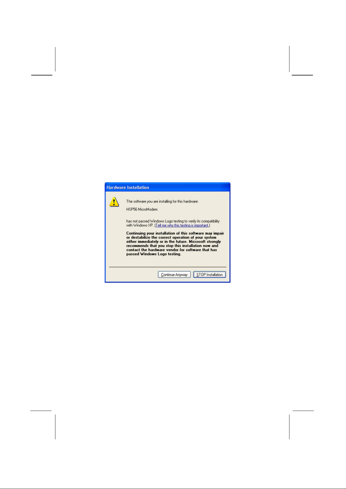
Notice:
Owing to Microsoft’s certifying schedule is various to every
supplier, we might have some drivers not certified yet by
Microsoft. Therefore, it might happen under Windows XP that a
dialogue box (shown as below) pop out warning you this
software has not passed Windows Logo testing to verify its
compatibility with Windows XP. Please rest assured that our RD
department has already tested and verified these drivers. Just
click the “Continue Anyway” button and go ahead the
insta llation.
Page 3

III
Table of Contents
Chapter 1: Introduction..............................................................1
Key Features......................................................................2
Package Contents............................................................... 5
Static Electricity Precautions............................................... 6
Pre-Installation Inspection ...................................................6
Chapter 2: Mainboard Installation............................................... 7
Mainboard Components ...................................................... 8
I/O Ports............................................................................8
Installing the Processor....................................................... 9
Installing Memory Modules .............................................. 10
Setting Jumper Switches................................................... 11
Install the Mainboard........................................................12
Connecting Optional Devices ............................................13
Install Other Devices ........................................................ 15
Expansion Slots ............................................................... 17
Chapter 3: BIOS Setup Utility.................................................. 18
Introduction..................................................................... 18
Running the Setup Utility...........…………………………...19
Standard CMOS Setup Page.............................................. 20
Advanced Setup Page.......................................................21
Power Management Setup Page......................................... 24
PCI/Plug and Play Setup Page........................................... 25
Load Optimal Settings ...................................................... 26
Load Best Performance Settings ........................................26
Features Setup Page.......................................................... 27
CPU PnP Setup Page ........................................................28
Hardware Monitor Page ....................................................29
Change Password............................................................. 30
Exit ................................................................................. 30
Chapter 4: Software & Applications.......................................... 31
About the Software & CD-ROM.......................................31
Utility Software Reference ................................................ 32
Appendis:Hyper Threading CPU.......................................34
Page 4

IV
Page 5

Chapter 1
Introduction
This mainboard has a Socket-478 processor socket for Intel
Pentium 4/Hyper Threading Technology processors with front -
side bus (FSB) speeds up to 533 MHz. Hyper Threading
Technology, designed to take advantage of the multitasking
features in Windows XP, gives you the power to do more things at
once.
This mainboard integrates the SiS651 Northbridge along with
SiS962L Southbridge chipsets that supports built-in AC97 Codec ,
2 DDR modules up to 2GB system memory, and provides Ultra
DMA 33/ 66/100/133 function. These chipsets’ function is detailed
as the Chipset description in next section. This mainboard
integrates a 256-bit 3D/2D Graphics Engine , Video Accelerator
and Advanced Hardware Acceleration MPEGI/MPEGII Video
Decoder for the Intel Pentium 4 series based PC systems. It has the
external AGP slot with AGP 4X 266MHz capability, one CNR
(Communications and Networking Riser) slot, and built-in
10BaseT/100BaseTX Network Interface(optional). In addition,
there is a full set of I/O Ports including PS/2 keyboard and mouse
ports, one serial port, one VGA port, one parallel port, and
maximum six USB2.0 ports – four back-panel ports and onboard
USB header JUSB1 providing two extra ports by connecting the
Extended USB Module to the mainboard.
This mainboard is ATX size and has power connectors for an ATX
power supply and measures 305 x 190mm.
Note: You must initiate the HT CPU function through
BIOS setup. It is strongly recommended you refer
to the Appendix (page 34) for relative details.
Page 6

2
Key Features
The key features of this mainboard include:
Socket-478 Processor
♦ The PGA Socket 478
♦ Supports Intel Pentium 4 series CPU with Hyper
Threading Technology
♦ Supports up to 533 MHz Front-Side Bus
Chipset
There are SiS651 Northbridge and SiS962L Southbridge in this
chipset in accordance with an innovative and scalable architecture
with proven reliability and performance. Here is a list of the
chipset arrangement and their respective features:
Northbridge Southbridge Function
SiS651 SiS962L CPU FSB: 533MHz, Ultra DMA
ATA133, DDR333, USB2.0
Supports Hyper-Threading
CPU
Memory Support
♦ Two 184-pin DIMM slots for DDR memory modules
♦ Maximum installed memory is 2GB
Expansion Slots
♦ One CNR slot
♦ One 2x/4xAGP slot for AGP 2.0-compliant interface
♦ Five 32-bit PCI slots for PCI 2.2 -compliant bus interface
Onboard IDE chann els
♦ Primary and Secondary PCI IDE channels
♦ Support for PIO (programmable input/output) modes
♦ Support for Multiword DMA modes
♦ Support for Bus Mastering and Ultra DMA ATA
33/66/100/133 modes
Power Supply and Power Management
♦ ATX power supply connector
Page 7

3
♦ Meets ACPI 1.0b and APM 1.2 requirements, keyboard
power on/off
♦ Supports RTC Alarm, Wake On Modem, AC97 Wake-Up
and USB Wake-Up
Onboard VGA
♦ Supports AGP V2.0 Compliant
♦ Supports AGP 4X/2X interface and Fast Write Transaction
♦ Supports high performance & high quality 3D
Accelerator —A built -in 256-bit 3D engine, up to 143 MHz
3D engine clock speed
♦ Supports high performance 128 -bit 2D Accelerator —Ultra-
AGPIITM 2GB/s data read for all 2D engine functions
♦ Maximum Share Memory size is 64MB
AC97 Audio Codec
♦ 6-CH hardware architecture allows multi-channel south
bridge to playback 6CH audio
♦ Intel AC’97 (REV. 2.2) compatible, meeting Microsoft
PC2001 requirements
♦ Built-in earphone buffer and internal PLL, the latter saving
additionsl crystal
♦ Line-in/rear out share the same jack; Center/bass share the
MIC jack
♦ Digital S/PDIF OUT Support
♦ CRL 3D: HRTF based BS3D compatible audio engine
Built-in Ethernet LAN (optional)
♦ 10Base-T/100Base-TX Physical Layer Solution
♦ Dual Speed – 100/10 Mbps
♦ MII Interface to Ethernet Controller/Configuration & Status
♦ Auto Negotiation: 10/100, Full/Half Duplex
♦ Meet All Applicable IEEE802.3, 10Base-T and 100Base -
TX Standards
Onboard I/O Ports
The mainboard has a full set of I/O ports and connectors:
♦ Two PS/2 ports for mouse and keyboard
Page 8

4
♦ One serial port
♦ One parallel port
♦ One VGA port
♦ Four back-panel USB2.0 ports and extra two USB2.0 ports
(onboard USB header JUSB1)
♦ Audio jacks for microphone, line-in and line-out
Hardware Monitoring
♦ Built-in hardware monitoring for CPU & System
temperatures, fan speeds and mainboard voltages.
Onboard Flash ROM
♦ Supports Plug and Play configuration of peripheral devices
and expansion cards
USB 2.0
♦ Compliant with Universal Serial Bus Specification
Revision 2.0
♦ Compliant with Intel’s Enhanced Host Controller
Interface Specification Revision 0.95
♦ Compliant with Universal Host Controller Interface
Specification Revision 1.1
♦ PCI multi-function device consists of two UHCI Host
Controller cores for full-/low-speed signaling and one
EHCI Host Controller core for high-speed signaling
♦ Root hub consists 4 downstream facing ports with
integrated physical layer transceivers shared by UHCI and
EHCI Host Controller
Support PCI -Bus Power Management Interface
♦
Specification release 1.1
♦ Legacy support for all downstream facing ports
Bundled Software
♦ PC-Cillin2002 provides automatic virus protection under
Windows 98/ME/NT/2000/XP
♦ MediaRing Talk provides PC to PC or PC to Phone
internet phone communication
♦ Super Voice is data, fax and voice communication software.
Page 9

5
♦ PageABC is the software to help you create your own
home page.
Dimensions
ATX form factor 305 x 190mm
♦
Package Contents
Your mainboard package contains the following items:
q The mainboard
q
The User’s Manual
q One diskette drive ribbon cable
q
One IDE drive ribbon cable
q Software support CD
Optional Accessories
You can purchase the following optional accessories for this
mainboard.
q Extended USB module
q Card Reader (You can buy your own Card Reader from the
third party, but please contact your local Card Reader vendor
on any issues of the specification and compatibility.)
Page 10

6
Static Electricity Precautions
Components on this mainboard can be damaged by static
electricity. Take the following precautions when unpacking the
mainboard and installing it in a system.
1. Keep the mainboard and other components in their original
static-proof packaging until you are ready to install them.
2. During installation, wear a grounded wrist strap if possible. If
you don’t have a wrist strap, discharge static electricity by
touching the bare metal of the system chassis.
3. Handle the mainboard carefully by the edges. Avoid touching
the components unless it is absolutely necessary. During
installation put the mainboard on top of the static-protection
packaging it came in with the component side facing up.
Pre-Installation Inspection
1. Inspect the mainboard for damage to the components and
connectors on the board.
2. If you suspect that the mainboard has been damaged, do not
connect power to the system. Contact your mainboard vendor
and report the damage.
Page 11

Chapter 2
Mainboard Installation
To install this mainboard in a system, please follow the instructions
in this chapter:
q Identify the mainboard components
q
Install a CPU
q Install one or more system memory modules
q Verify that all jumpers or switches are set c orrectly
q Install the mainboard in a system chassis (case)
q Connect any extension brackets or cables to connecting
headers on the mainboard
q Install other devices and make the appropriate connections to
the mainboard connecting headers.
Note:
1. Before installing this mainboard, make sure jumper JP2 is
under Normal setting. See this chapter for information about
locating JP2 and the setting options.
2. Never connect power to the system during installation;
otherwise, it may damage the mainboard.
Page 12
8
(optional)
(shared
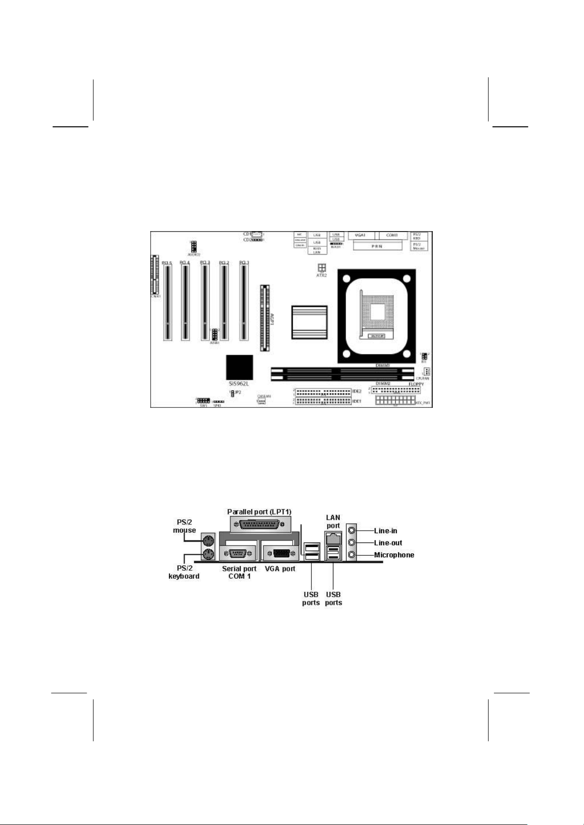
Mainboard Components
Use the diagram below to identify the major components on the
mainboard.
Note: Any jumpers on your mainboard not appearing in the
illustration above are for testing only.
I/O Ports
The illustration below shows a side view of the built-in I/O ports
on the mainboard.
with
READ1)
Page 13

9
PS/2 Mouse
Use the upper PS/2 port to connect a PS/2
pointing device.
PS/2 Ke yboard
Use the lower PS/2 port to connect a PS/2
keyboard.
LPT1
Use LPT1 to connect printers or other
parallel communications devices.
COM1
Use the COM port to connect serial devices
such as mice or fax/modems. COM1 is
identified by the system as COM1.
VGA
LAN Port
(optional)
USB Po rts
Audio Ports
Use the VGA port to connect VGA devices.
Connect an RJ-45 jack to the LAN port to
connect your computer to the Network.
Use the USB ports to connect USB devices.
Note: The lower USB port located beside the
VGA port is shared with the READ1 co nnector.
Use the three audio ports to connect audio
devices. The first jack is for stereo Line-In
signal. The second jack is for stereo
Line-Out signal. The third jack is for
Microphone.
Installing the Processor
This mainboard has a Socket 478 processor socket. When choosing
a processor, consider the performance requirements of the system.
Performance is based on the processor design, the clock speed and
system bus frequency of the processor, and the quantity of internal
cache memory and external cache memory.
CPU Installation Procedure
Follow these instructions to install the CPU:
1. Unhook the CPU socket’s locking lever by pulling
it away from socket and raising it to the upright
position.
2. Match the pin 1 corner of CPU socket to the one of
processor, and insert the processor into the socket.
Do not use force.
3. Push the locking lever down and hook it under the
latch on the edge of socket.
Page 14

10
DIMM1
DIMM2
4. Apply thermal grease to the top of the CPU.
5. Lower the CPU fan/heatsink unit onto the CPU and
CPU socket, and then use the retention module
clamps to snap the fan/heatsink into place.
6. Plug the CPU fan power cable into the CPU
cooling fan power supply (CPUFAN) on the
mainboard.
Installing Memory Modules
This mainboard accommodates two 184-pin 2.5V unbuffered
Double Data Rate SDRAM (DDR SDRAM) Dual Inline Memory
Module (DIMM) sockets, and supports up to 2.0 GB
of 266/333 MHz DDR SDRAM.
DDR SDRAM is a type of SDRAM that supports data transfers on
both edges of each clock cycle (the rising and falling edges),
effectively doubling the memory chip’s data throughput. DDR
DIMMs can synchronously work with 100 MHz or 133 MHz
memory bus.
DDR SD RAM provides 1.6 GB/s or 2.1 GB/s data transfer rate
depending on whether the bus is 100 MHz or 133 MHz.
DDR SDRAM uses additional power and ground lines and requires
184-pin 2.5V unbuffered DIMM module.
Installation Procedure
These modules can be installed with up to 2 GB system memory.
Refer to the following steps to install the memory module.
Page 15

11
1. Push the latches on each side of the DIMM socket
JP2
1
down.
2. Align the memory module with the socket. The
DIMM sockets are keyed with notches and the
DIMMs are keyed with cutouts so that they can
only be installed correctly.
3. Check that the cutouts on the DIMM module edge
connector match the notches in the DIMM socket.
4. Install the DIMM module into the socket and press
it firmly down until it is seated correctly. The
socket latches are levered upwards and latch on to
the edges of the DIMM.
5. Install any remaining DIMM modules.
Setting Jumper Switches
Jumpers are sets of pins that can be connected together with
jumper caps. The jumper caps change the way the mainboard
operates by changing the electronic circuits on the mainboard. If a
jumper cap connects two pins, we say the pins are SHORT. If a
jumper cap is removed from two pins, the pins are OPEN.
Jumper JP2: Clear CMOS Memory
This jumper can clear the contents of the CMOS memory. You
may need to clear the CMOS memory if the settings in the Setup
Utility are incorrect and prevent your mainboard from operating.
To clear the CMOS memory, disconnect all the power cables from
the mainboard and then move the jumper cap into the CLEAR
setting for a few seconds.
Page 16

12
ATXPW1
1
SW1
ATX2
CHSFAN
1
Function Jumper Setting
Clear CMOS Short Pins 1-2
Normal Mode Short Pins 2-3
Install the Mainboard
Install the mainboard in a system chassis (case). The board is a
Micro ATX size mainboard. You can install this mainboard in an
ATX case. Ensure your case has an I/O cover plate that matches
the ports on this mainboard.
Install the mainboard in a case. Follow the instructions provided by
the case manufacturer using the hardware and internal mounting
points on the chassis.
Connect the power connector from the power supply to the
ATXPW1 connector on the mainboard. ATX2 is the CPU Vcore
power connector.
If there is a cooling fan installed in the system chassis, connect the
cable from the cooling fan to the CHSFAN fan power connector
on the mainboard.
Connect the case switches and indicator LEDs to the SW1 header.
Pin Signal Pin Signal
1 HDD_LED_P 2 FP ACPI LED
3 HDD_LED_N 4 FP ACPI LED
5 RST_SW_N 6 PW_BT_P
7 RST_SW_P 8 PW_BT_N
9 RSVD_DNU 10 KEY
Page 17

13
Connecting Optional Devices
1
SPK1
1
AUDIO2
1
1
IR1
READ1
1
Refer to the following for information on connecting the
mainboard’s optional devices:
JUSB1
SPK1: Speaker Connector
Connect the cable from the PC speaker to the SPK1 header on the
mainboard .
Pin Signal Pin Signal
1 SPKR 2 NC
3 GND 4 +5V
AUDIO2: Front Panel Audio Header
This header allows the user to install auxiliary front-oriented
microphone and line -out ports for easier access.
Pin Signal Pin Signal
1 AUD_MIC 2 AUD_GND
3 AUD_MIC 4 AUD_VCC
5 AUD_FPOUT 6 AUD_RET_R
7 NC 8 KEY
9 AUD_FPOUT 10 AUD_RET_L
JUSB1: Front panel USB Connector
The mainboard has USB ports installed on the rear edge I/O port
array. Additionally, some computer cases have USB ports at the
front of the case. If you have this kind of case, use auxiliary USB
connector USB3 to connect the front-mounted ports to the
mainboard.
Page 18

14
Pin Signal Pin Signal
1 VCC 2 VCC
3 DATA1- 4 DATA2-
5 DATA1+ 6 DATA2+
7 GND 8 GND
9 KEY 10 NC
1. Locate the JUSB1 header on the mainboard.
2. Plug the bracket cable onto the JUSB1 header.
3. Remove a slot cover from one of the expansion slots on the
system chassis. Install an extension bracket in the opening.
Secure the extension bracket to the chassis with a screw.
READ1: USB Card Reader Connector (optional)
This connector is for connecting internal USB card reader. You can
use a card reader to read or transfer files and digital images to your
computer.
Pin Signal Pin Signal
1 VCC 2 USB3 USB+ 4 GND
5 KEY
The JUSBC is shared with one of the USB ports of the I/O
back panel. The USB port is located beside the serial port
connectors. See “I/O Ports” for more information.
Please check the pin assignment of the cable and the USB
header on the mainboard. Make sure the pin assignment
will match before plugging in. Any incorrect usage may
cause unexpected damage to the system. The vendor won’t
be responsible for any incidental or consequential damage
arising from the usage or misusage of the purchased
product.
IR1: Infra red Port
The infrared port allows the wireless exchange of information
between your computer and similarly equipped devices such as
printers, laptops, Personal Digital Assistants (PDAs), and other
computers.
Page 19

15
Pin Signal Pin Signal
1
1
1
1 NC 2 KEY
3 +5V 4 GND
5 IRTX 6 IRRX
1. Locate the infrared port IR1 header on the mainboard.
2. If you are adding an infrared port, connect the ribbon cable
from the port to the IR1 header and then secure the port to an
appropriate place in your system chassis.
Install Other Devices
Install and connect other devices in the system as steps below.
IDE2 FLOPPY
IDE1
Floppy Disk Drive
The mainboard ships with a floppy disk drive cable that can
support one or two drives. Drives can be 3.5” or 5.25” wide, with
capacities of 360K, 720K, 1.2MB, 1.44MB, or 2.88MB.
Install your drives and connect power from the system power
supply. Use the cable provided to connect the drives to the floppy
disk drive connector FLOPPY.
IDE Devices
IDE devices include hard disk drives, high-density diskette drives,
and CD-ROM or DVD-ROM drives, among others.
The mainboard ships with an IDE cable that can support one or two
IDE devices. If you connect two devices to a single cable, you
must configure one of the drives as Master and one of the drives as
Slave. The documentation of the IDE device will tell you how to
Page 20

16
1
1
configure the device as a Master or Slave device. The Master
device connects to the end of the cable.
Install the device(s) and connect power from the system power
supply. Use the cable provided to connect the device(s) to the
Primary IDE channel connector IDE1 on the mainboard.
If you want to install more IDE devices, you can purchase a second
IDE cable and connect one or two devices to the Secondary IDE
channel connector IDE2 on the mainboard. If you have two
devices on the cable, one must be Master and one must be Slave.
Internal Sound Connections
If you have installed a CD-ROM drive or DVD-ROM drive, you
can connect the drive audio cable to the onboard sound system.
CD1
CD2
When you first start up your system, the BIOS should
automatically detect your CD-ROM/DVD drive. If it doesn’t, enter
the Setup Utility and configure the CD -ROM/DVD drive that you
have installed. On the mainboard, locate the two 4-pin connectors
CD1 and CD2.
CD1 CD2
Pin Signal Pin Signal
1 GND 1 CD IN L
2 CD IN R 2 GND
3 GND 3 GND
4 CD IN L 4 CD IN R
Page 21

17
Expansion Slots
CNR1
PCI1
PCI2
AGP1
PCI3
PCI4
PCI5
This mainboard has one AGP, one CNR and five 32-bit PCI slots.
Follow the steps below to install one AGP/CNR/PCI expansion
card.
1. Locate the AGP, CNR or PCI slots on the mainboard.
2. Remove the blanking plate of the slot from the system chassis.
3. Install the edge connector of the expansion card into the slot.
Ensure the edge connector is correctly seated in the slot.
4. Secure the metal bracket of the card to the system chassis with
a screw.
Page 22

18
Chapter 3
BIOS Setup Utility
Introduction
The BIOS Setup Utility records settings and information about
your computer such as the date and time, the kind of hardware
installed, and various configuration settings. Your computer uses
this information to initialize all the components when booting up
and functions as the basis for coordination between system
components.
If the Setup Utility configuration is incorrect, it may cause the
system to malfunction. It can even stop your computer from
booting properly. If this happens, you can use the clear CMOS
jumper to clear the CMOS memory used to store the configuration
information.
You can run the setup utility and manually make changes to the
configuration. You might need to do this to configure some of the
hardware that you install on or connect to the mainboard, such as
the CPU, system memory, disk drives, etc.
Page 23

19
Running the Setup Utility
Each time your computer starts, before the operating system loads,
a message appears on the screen that prompts you to “Hit <DEL>
if you want to run SETUP ”. When you see this message, press the
Delete key and the Main menu page of the Setup Utility appears on
your monitor.
AMIBIOS SIMPLE SETUP UTILITY – VERSION 1.21.12
(C) 2000 American Megatrends, Inc. All Rights Reserved
Standard CMOS Setup
Advanced Setup
Power Management Setup
PCI / Plug and Play Setup
Load Optimal Settings
Load Best Performance Settings
Esc : Quit ↑ ↓ ← →: Select Item (Shift)F2 : Change Color F5 : Old Values
F6 : Optimal values F7 : Best performance values F10 : Save&Exit
Features Setup
CPU PnP Setup
Hardware Monitor
Change Password
Exit
Standards COMOS setup for changing time, date, hard disk type, etc.
You can use the cursor arrow keys to highlight any of the options
on the main menu page. Press Enter to select the highlighted
option. To leave the setup utility, press the Escap e key. To cycle
through the Setup Utility’s optional color schemes hold down the
Shift key and press F2 .
Some of the options on the main menu page lead to tables of items
with installed values. In these pages, use the cursor arrow keys to
highlight the ite ms, and then use the PgUp and PgDn keys to cycle
through the alternate values for each of the items. Other options on
the main menu page lead to dialog boxes requiring you to answer
Yes or No by hitting the Y or N keys.
If you have already made changes to the setup utility, press F10 to
save those changes and exit the utility. Press F5 to reset the
changes to the original values. Press F6 to install the setup utility
with a set of default values. Press F7 to install the setup utility with
a set of high-performance values.
Page 24

20
Standard CMOS Setup Page
Use this page to set basic information such as the date, the time,
the IDE devices, and the diskette drives. If you press the F3 key,
the system will automatically detect and configure the hard disks
on the IDE channels.
AMIBIOS SETUP – STANDARD CMOS SETUP
(C) 2000 American Megatrends, Inc. All Rights Reserved
Date (mm/dd/yy) : Thu Mar 20, 2003
Time (hh/mm/ss) : 15:32:20
LBA Blk PIO 32Bit
Type Size Cyln Head WPcom Sec Mode Mode Mode Mode
Pri Master : Auto On
Pri Slave : Auto On
Sec Master : Auto On
Sec Slave : Auto On
Floppy Drive A : 1.44 MB 3 1/2
Floppy Drive B : Not Installed
Month : Jan – Dec ESC : Exit
Day : 01 – 31 ↑↓ : Select Item
Year : 1901 – 2099 PU/PD/+/- : Modify
(Shift)F2 : Color
F3 : Detect All HDD
Date & Time Use these items to set the system date and time
Pri Master
Pri Slave
Sec Master
Sec Slave
Use these items to configure devices connected
to the Primary and Secondary IDE channels.
To configure an IDE hard disk drive, choose
Auto. If the Auto setting fails to find a hard
disk drive, set it to User, and then fill in the
hard disk characteristics (Size, Cyls, etc.)
manually. If you have a CD-ROM drive, select
the setting CDROM. If you have an ATAPI
device with removable media (e.g. a ZIP drive
or an LS-120) select Floptical.
Floppy Drive A
Floppy Drive B
Use these items to set the size and capacity of
the floppy diskette drive(s) installed in the
system.
Page 25

21
Advanced Setup Page
This page sets up more advanced information in the system. Be
more carful with this page. Making changes can affect the
operation of your computer.
AMIBIOS SETUP – ADVANCED SETUP
(C) 2000 American Megatrends, Inc. All Rights Reserved
Quick Boot Enabled
Card Reader Boot Function Disabled
1st Boot Device IDE-0
2nd Boot Device Floppy
3rd Boot Device CDROM
Try Other Boot Devices Yes
S.M.A.R.T. for Hard Disks Disabled
BootUp Num -Lock On
Floppy Drive Swap Disabled
Floppy Drive Seek Disabled
Password Check Setup
Boot To OS/2 > 64MB No
L2 Cache Enabled
System BIOS Cacheable Disabled
Share Memo ry Size 32 MB
Graphic Win Size 4MB
DRAM CAS# Latency 3T
Timing Setting Mode Normal
MA 1T/2T Select MA 2T
Advanced Read Prefetch Enabled
Hyper Threading Function Disabled
Quick Boot If you enable this item, the system starts
up more quickly be elimination some of
the power on test routines.
Card Reader Boot
Function
1st Boot Device
2nd Boot Device
3rd Boot Device
Try Other Boot
Device
If this item is enabled, you can use this
device to boot up the system.
Use these items to determine the device
order the computer uses to look for an
operating system to load at start-up time.
If you enable this item, the system will
also search for other boot devices if it
fails to find an operating system from the
first two locations.
Auto Detect DIMM/PCI Clk Enabled
Spread Spectrum Disabled
DOS Flat Mode Disabled
ESC : Quit
F1 : Help PU/PD/+/ - : Modify
F5 : Old Values (Shift)F2 : Color
F6 : Load BIOS Defaults
F7 : Load Setup Defaults
↑↓←→
: Select Item
Page 26

22
S.M.A.R.T. for Hard
Disks
Enable this item if any IDE hard disks
support the S.M.A.R.T. (Self Monitoring, Analysis and Reporting
Technology) feature.
BootUp Num-Lock This item determines if the Num Lock
key is active or inactive at system startup time.
Floppy Drive Swap If you have two diskette drives installed
and you enable this item, drive A
becomes drive B and drive B becomes
drive A.
Floppy Drive Seek If you enable this item, your system will
check all floppy disk drives at start up.
Disable this item unless you are using an
old 360KB drive.
Password Check If you have entered a password for the
system, use this item to determine, if the
password is required to enter the Setup
Utility (Setup) or required both at start-
up and to enter the Setup Utility
(Al ways).
Boot to OS/2 > 64MB Enable this item if you are booting the
OS/2 operating system and you have
more than 64MB of system memory
installed.
L2 Cache Leave these items enabled since all the
processors that can be installed on this
board have internal L2 cache memory.
System BIOS
Cacheable
If you enable this item, a segment of the
system BIOS will be copied to main
memory for faster execution.
Share Memory Size This item lets you allocate a portion of
the main memory for the onboard VGA
display application with five options of
4/8/16/32/64 MB.
Page 27

23
Graphic Win Size This item defines the size of aperture if
you use a graphic adapter.
DRAM CAS# Latency This item determines the operation of
DRAM memory CAS (column address
strobe). It is recommended that you leave
this item at the default value. The 3T
setting requires faster memory that
specifically supports this mode.
Timing Setting Mode This item determines the timing setting
mode of the memory. We recommend
you leave this item at the default value.
MA 1T/2T Select This item adjusts timing 1T/2T latency.
We recommend you to leave this item at
the default value.
Advanced Read
Prefetch
This item enables prefetching for reading
data. We recommend you to leave this
item at the default value.
Hyper Threading
Function
If your P4 CPU is not HT CPU, this item
will be hidden.
If your P4 CPU is HT CPU, BIOS will
show this item. You can set "Disabled"
or "Enabled" to control HT CPU support
in O.S. Set “Enabled” to test HT CPU
function.
Auto Detect
DIMM/PCI Clk
When this item is enabled, BIOS will
disable the clock signal of free
DIMM/PCI slots.
Spread Spectrum If you enable spread spectrum, it can
significantly reduce the EMI(ElectroMagnetic Interference) generated by the
system.
DOS Flat Mode This item enables BIOS entering the
DOS protected mode without other
software supporting under the DOS
operating system. We recommend you to
leave this item at the default value.
Page 28

24
Disabled
Power Management Setup Page
This page sets some of the parameters for system power
management operation.
AMIBIOS SETUP – POWER MANAGEMENT SETUP
(C) 2000 American Megatrends, Inc. All Rights Reserved
Power Management Enabled
Suspend Time out Disabled
Hard Disk Time out Disabled
Resume On RTC Alarm
RTC Alarm Date 15
RTC Alarm Hour 12
RTC Alarm Minute 30
RTC Alarm Second 30
LAN/Ring Power On Disabled
Keyboard Power On Disabled
ACPI Aware O/S Enable this item if you are using an O/S that
ACPI Aware O/S Yes
ESC : Quit
F1 : Help PU/PD/+/ - : Modify
F5 : Old Values (Shift)F2 : Color
F6 : Load BIOS Defaults
F7 : Load Setup Defaults
↑↓←→
: Select Item
supports ACPI function such as Windows
98/ME /2000.
Power
Management
Suspend Time Out This sets the timeout for Suspend mode in
Use this item to select a power management
scheme. Both APM and ACPI are supported.
minutes. If the time selected passes without
any system activity, the computer will enter
power-saving Suspend mode.
Hard Disk Time
Out
This sets the timeout to power down the hard
disk drive, if the time selected passes without
any hard disk activity.
Resume On RTC
Alarm Date / Hour /
Minute / Second
The system can be turned off with a software
command. If you enable this item, the system
can automatically resume at a fixed time
based on the system’s RTC (realtime clock).
Use the items below this one to set the date
and time of the wake -up alarm. You must use
an ATX power supply in order to use this
feature.
Page 29

25
LAN/Ring Power
On
KeyBoard Power
On
PCI / Plug and Play Setup Page
This page sets some of the parameters for devices installed on the
PCI bus and devices that use the system plug and play capability.
Primary Graphics Adapter PCI
Allocate IRQ to PCI VGA Yes
PCI IDE BusMa ster Disabled
Plug and Play
Aware O/S
Primary Graphics
Adapter
The system can be turned off with a software
command. If you enable this item, the system
can automatically resume if there is an
incoming call on the Modem. You must use
an ATX power supply in order to use this
feature.
If you enable this item, you can turn the
system on and off by pressing hot keys on the
keyboard. You must enable the Keyboard
Power On jumper and use an ATX power
supply in order to use this feature.
AMIBIOS SETUP – PCI / PLUG AND PLAY SETUP
(C) 2000 American Megatrends, Inc. All Rights Reserved
Plug and Play Aware O/S Yes
ESC : Quit
F1 : Help PU/PD/+/ - : Modify
F5 : Old Values (Shift)F2 : Color
F6 : Load BIOS Defaults
F7 : Load Setup Defaults
↑↓←→
Enable this it em if you are using an O/S that
supports Plug and Play such as Windows
95/98/ME.
This item indicates if the primary graphics
adapter uses the PCI or the AGP bus. The
default PCI setting still lets the onboard
display work and allows the use of a second
display card installed in a PCI slot.
: Select Item
Page 30

26
Allocate IRQ to
PCI VGA
If this item is enabled, an IRQ will be
assigned to the PCI VGA graphics system.
You set this value to No to free up an IRQ.
PCI IDE BusMaster This item enables or dis ables the DMA under
DOS mode. We recommend you to leave this
item at the default value.
Load Optimal Settings
If you select this item and press Enter a dialog box appears. If you
press Y, and then Enter, the Setup Utility loads a set of fail-safe
default values. These default values are not very demanding and
they should allow your system to function with most kinds of
hardware and memory chips.
Note: It is highly recommended that users enter this option to
load optimal values for accessing the best performance.
Load Best Performance Settings
If you select this item and press Enter a dialog box appears. If you
press Y, and then Enter, the Setup Utility loads a set of best -
performance default values. These default values are quite
demanding and your system might not function properly if you are
using slower memory chips or other low -performance components.
Page 31

27
Features Setup Page
Disabled
This page sets some of the parameters for peripheral devices
connected to the system.
OnBoard Serial Port 3F8h/COM1
OnBoard IR Port Disabled
OnBoard Parallel Port 378h
Parallel Port Mode ECP
Parallel Port IRQ 7
Parallel Port DMA 3
OnBoard PCI IDE Both
Audio Device Enabled
Modem Device Enabled
Ethernet Device Enabled
Onboard USB Function Enabled
USB Function for DOS Disabled
ThumbDrive for DOS
OnBoard FDC Use this item to enable or disable the onboard
OnBoard Serial
Port
OnBoard IR Port Use this item to enable or disable the onboard
Onboard Parallel
Port
Parallel Port Mode Use this item to set the parallel port mode.
Parallel Port IRQ Use this item to assign either IRQ 5 or 7 to
AMIBIOS SETUP – FEATURES SETUP
(C) 2000 American Megatrends, Inc. All Rights Reserved
OnBoard FDC Enabled
ESC : Quit
F1 : Help PU/PD/+/ - : Modify
F5 : Old Values (Shift)F2 : Color
F6 : Load BIOS Defaults
F7 : Load Setup Defaults
↑↓←→
floppy disk drive interface.
Use these items to enable or disable the
onboard COM1 serial port, and to assign a
port address.
infrared port, and to assign a port address.
Use this item to enable or disable the onboard
LPT1 parallel port, and to assign a port
address. The Auto setting will detect and
available address.
You can select SPP (Standard Parallel Port),
ECP (Extended Capabilities Port), EPP
(Enhanced Parallel Port), or ECP + EPP.
the parallel port.
: Select Item
Page 32

28
Parallel Port DMA Use this item to assign a DMA channel to the
parallel port. The options are 0, 1 and 3.
Onboard PCI IDE Use this item to enable or disable either or
both of the onboard Primary and Secondary
IDE channels.
Audio Device This item enables or disables the onboard
AC’97 audio chip.
Modem Device This ite m enables or disables the onboard
AC’97 modem chip.
Ethernet Device This item enables or disables the onboard
Ethernet LAN.
Onboard USB
Function
USB Function for
DOS
Enable this item if you plan to use the USB
ports on this mainboard.
Enable this it em if you plan to use the USB
ports on this mainboard in a DOS
environment.
ThumbDrive for
DOS
Enable this item to make a small portion of
memory storage device for the USB ports.
CPU PnP Setup Page
This page lets you manually configure the mainboard for the CPU.
The system will automatically detect the kind of CPU that you
have installed and make the appropriate adjustments to the items
on this page.
AMIBIOS SETUP – CPU PnP SETUP
©2000 American Megatrends, Inc. All Rights Reserved
CPU Type Intel P4
CPU/DRAM Speed 100/100 MHz
CPU Core Voltage 1.632V
CPU Ratio H/W TRAP
CPU Frequency 100 MHz
DRAM Frequency 100 MHz
ESC : Quit
F1 : Help PU/PD/+/- : Modify
F5 : Old Values (Shift)F2 : Color
F6 : Load Optimal values
F7 : Load Best performance values
↑↓←→
: Select Item
Page 33

29
F
CPU Type/Core
Voltage/Ratio/
Frequency
CPU/DRAM
Speed/Frequency
These items show the type, core voltage,
ratio and frequency of CPU installed in your
system.
These items decide CPU/DRAM
speed/frequency installed in your system.
Hardware Monitor Page
This page sets some of the parameters for the hardware monitoring
function of this mainboard.
AMIBIOS SETUP – HARDWARE MONITOR
(C) 2000 American Megatrends, Inc . All Rights Reserved
Vcore 1.616V
Vcc 1.8V 1.792V
Vcc 3.3V 3.392V
Vcc 4.945V
+12V 12.032V
Vcc2.5V 2.532V
SB5V 4.962V
VBAT 3.472V
SYSTEM Fan Speed 0 RPM
CPU Fan Speed 1308 RPM
SYSTEM Temperature 33°C/91°F
CPU Temperature 41°C/105
System/ CPU
Temperature
FANs & Voltage
Measurements
These items display Power, CPU and System
temperature measurement.
These items indicate cooling fan speeds in
RPM and the various system voltage
measurements.
*** System Hardware ***
ESC : Quit
F1 : Help PU/PD/+/ - : Modify
F5 : Old Values (Shift)F2 : Color
°
F6 : Load BIOS Defaults
F7 : Load Setup Defaults
↑↓←→
: Select Item
Page 34

30
Change Password
If you highlight this it em and press Enter, a dialog box appears
which lets you enter a Supervisor password. You can enter no more
than six letters or numbers. Press Enter after you have typed in the
password. A second dialog box asks you to retype the password for
confirmation. Press Enter after you have retyped it correctly. The
password is then required to access the Setup Utility or for that and
at start-up, depending on the setting of the Password Check item in
Advanced Setup.
Change or Remove the Password
Highlight this it em, press Enter and type in the current password.
At the next dialog box, type in the new password, or just press
Enter to disable password protection.
Exit
Highlight this item and press Enter to save the changes that you
have made in the Setup Utility configuration and exit the program.
When the Save and Exit dialog box appears, press Y to save and
exit, or press N to exit without saving.
Page 35

Chapter 4
About the Software & CD- ROM
The support software CD-ROM that is included in the mainboard
package contains all the drivers and utility programs needed to
properly run the bundled products. Below you can find a brief
description of each software program, and the location for your
mainboard version. More information on some programs is
available in a README file, located in the same directory as the
software.
Note: Never try to install software from a folder that is not
specified for use with your mainboard.
Before installing any software, always inspect the folder for files
named RE ADME.TXT, INSTALL.TXT, or something similar.
These files may contain important information that is not included
in this manual.
Page 36

32
Utility Software Reference
All the utility software available on the CD-ROM is Windows
compliant. It is provided only for the convenience of customers.
The following software is furnished under license and may only be
used or copied in accordance with the terms of the license.
Note: The software in these folders is subject to change at anytime
without prior notice. Please refer to the support CD for
available software.
AMI Flash Memory Utility
This utility enables you to erase the system BIOS stored on a Flash
Memory chip on the mainboard, and lets you copy an updated
version of the BIOS to the chip. Proceed with caution when using
this program. If you erase the current BIOS and fail to write a new
BIOS, or write a new BIOS that is incorrect, your system will
malfunction. Refer to Chapter 3, Using BIOS for more information.
PC-CILLIN 2002
The PC-CILLIN software program provides anti-virus pr otection
for your sy stem. This program is available for Windows
XP/2000/ME/98SE and Windows NT. Be sure to check the
readme.txt and install the appropriate anti -virus software for your
operating system.
We strongly recommend users to install this free anti-virus
software to help protect your system against viruses.
Note: Update your virus software regularly to protect against new
viruses.
MediaRing Talk – Telephony Software
To install the MediaRing Talk voice modem software for the builtin modem, run Setup.EXE from the follo wing directory:
\UTILITY \MEDIARING TALK
Page 37

33
Super Voice – Fax/Modem Software
To install the Super Voice voice, fax, data communication
application for use with the built-in fax/modem, run
PICSHELL.EXE from the following directory:
\UTILITY\SUPER VOICE
PageABC
The PageABC application software enables you to create your own
home page. To install the PageABC, run SETUP.EXE from the
following directory:
\UTILITY \PageABC
Page 38

34
Appendix: Hyper Threading CPU
You must update BIOS to initiate BIOS Hyper Threading Function
and use HT CPU function under WinXP Operating System; if not,
please disable this option.
♦ When BIOS detects the HT CPU, it shows the “Hyper
Threading Function (default Disabled)” option, which you must
set Enabled if you want to test HT CPU function. If there is no
HT CPU, this option is hidden and default Disabled.
♦ You must re-install WINXP to activate the HT CPU function.
While you are in Windows Task Manager, please push down
ctrl+Alt Del keys. A dual CPU appears in the CPU Usage
History&Device Manager under WinXP.
Note: Hyper Threading Function only works under
WINXP Operating System; therefore, disable it
under other Operating System.
 Loading...