

Page 1

The information presented in this publication has been
carefully checked for reliability; however, no responsibility is assumed for inaccuracies. Specifications are subject
to change without notice.
Trademarks
PS/2, OS/2, IBM, PC/AT, and PC/XT are registered trademarks of
International Business Machines Corporation.
Intel, Celeron and Pentium® II/III are registered trademarks of Intel
Corporation.
Award is a registered trademark of Award Software Inc.
MS-DOS, Windows 3.1/95/98/NT, Direct Sound 3D and Direct Mu-
sic are registered trademarks of Microsoft Corporation.
A3D is a registered trademark of Aureal Inc.
Sound Blaster is a registered trademark of Creative Technology, Ltd.
PC-cillin and ChipAway Virus are registered trademarks of Trend
Micro, Inc.
SiS is a registered trademark of Silicon Integrated Systems
Corporation.
Copy right (C) 1999.
All Rights Reserved.
MS7380SG, Version 1.1
S6X/March 1999
Page 2

ii Contents
Chapter 1: Introduction ........................................................................... 0
Key Features ........................................................................................ 1
Unpacking the Mainboard & Static Electricity Precautions ................ 3
Notice ................................................................................................... 4
Chapter 2: Hardware Configuration ...................................................... 5
Mainboard Component Locations ....................................................... 6
CPU Installation ................................................................................... 7
Installation Procedures .................................................................... 8
CPU Speed Setting .......................................................................... 10
Memory Installation ............................................................................. 11
Jumper Settings .................................................................................... 12
J12 - CMOS RAM Clear Selector ................................................... 12
J13 - Keyboard Power On Selector ................................................. 12
ATX Functions & Connectors ............................................................. 13
Software Power-Off ........................................................................ 13
Modem Ring Power Up .................................................................. 13
Alarm Wake Up .............................................................................. 13
Keyboard Power On ........................................................................ 13
PWR1 - ATX Power Connector ...................................................... 14
J10(21,22) - Power Button/Suspend Switch Connector .................. 14
J4 - Wake On LAN Connector ........................................................ 14
Connectors ............................................................................................ 15
External Connectors Location ......................................................... 15
FDC1 - Floppy Disk Port ................................................................. 16
IDE1/IDE2 - Primary/Secondary IDE Ports .................................... 16
FAN1,2 - Fan Power Connectors ..................................................... 16
IR - InfraRed Connector .................................................................. 17
J10 - Case Connectors ..................................................................... 18
Page 3

iii
Onboard PCI Sound ..............................................................................19
Sound and Game .............................................................................19
CD1/CD2 - Analog Audio from CD-ROM .....................................19
J16 - Digital Audio Connector ........................................................20
J6 - SPDIF OUT Signal Level Selector ..........................................20
J17 - Internal SPDIF IN Connector ................................................20
Notice for PCI Sound application ...................................................21
The Four Speakers System ..............................................................22
Onboard VGA .......................................................................................23
Chapter 3: BIOS Setup ...........................................................................24
Running the Setup Utility .....................................................................25
Standard CMOS Setup Page .................................................................26
BIOS & CPU Features Setup Page .......................................................27
Chipset Features Setup Page .................................................................29
Power Management Setup Page ...........................................................31
PnP / PCI Configuration Page ..............................................................34
Load BIOS Defaults .............................................................................35
Load Setup Defaults .............................................................................35
Integrated Peripherals Setup Page ........................................................36
Password Settings .................................................................................38
Change or Remove the Password ...................................................38
IDE HDD Auto Detection ....................................................................38
Save and Exit Setup ..............................................................................38
Exit Without Saving ..............................................................................39
Chapter 4: Software Driver ....................................................................40
Page 4

Chapter 1
Introduction
This mainboard is a SiS 620 100MHz high-performance
mainboard based on the Slot 1 microprocessor, and provides CPU Plug and Play feature for faster and easier CPU
installation. The mainboard features with highly flexible
configurations and is fully IBM PC/AT compatible.
The mainboard uses a highly integrated Slot 1 chipset with
3D video inside that is built-in a high performance 64-bit
3D AGP Graphics Accelerator with 8MB frame buffer
shared from system memory. It supports the PCI/ISA and
Green standards, it provides the Host/AGP bridge, and
integrates all system control functions such as ACPI
(Advanced Configuration and Power Interface). The ACPI
provides more energy saving features for the OSPM(OS
Direct Power Management) function.
The mainboard has an onboard 3D PCI Sound to meet
PC98 Audio requirement. It is also
Monitor circuit for abnormal CPU fan speed/temperature/
voltages detection. The mainboard BIOS provides Trend’s
ChipAway Virus to ensure the entire boot process virus
free.
built-in Hardware
Page 5

Introduction 1
Key Features
The advanced features of the mainboard include:
Supports Pentium® II 233~450 MHz, Celeron 266~433 MHz and
Pentium III (Katmai New Instruction) 450~500 MHz CPUs.
- supports both 66.6MHz and 100MHz FSB (Front Side Bus).
- provides CPU Plug and Play feature for faster and easier CPU
installation.
Provides 3 DIMMs for SDRAM memory modules.
- supports a maximum size of 768MB system memory.
Provides 3 PCI and 1 ISA slots.
Onboard 2 channel IDE,
- supports four IDE devices maximum.
- supports PIO, Bus Master and Ultra DMA 33/66 operation modes.
Provides ATX power connectors and features of ATX power,
- Power Button/Suspend Switch and Keyboard Power On.
- Alarm Wake Up, Modem Wake Up and Wake On LAN.
Onboard 64-bit 3D AGP Graphics Accelerator,
- AGP 2.0 spec. compliant.
- built in 8-way/16-entry setassociative GART cache for AGP
- maximum 8MB frame buffer share from system memory.
- high resolution graphic modes up to 1600 x 1200.
Onboard PCI Sound meets PC98' specifications,
- full duplex playback and recording, built-in 16-bits CODEC.
- HRTF 3D positional audio, supports both Direct Sound 3D® &
A3D® interfaces, and support four channel speakers mode.
- supports Windows 3.1/95/98 and Windows NT 4.0.
- built-in 32 ohm earphone buffer and 3D surround.
Page 6

2 Chapter 1
- supports MPU-401 Game/Midi port and legacy audio SB16.
- downloadable Wave-table Synthesizer support Direct Music®.
- Digital Audio Interface(SPDIF) IN/OUT up to 24-bit stereo
44KHz sampling rate voice and measured 120dB audio quality.
- Stereo Mixer supports analog mixing from CD-Audio, Line-In,
and digital mixing from voice, FM/Wave-table and digital CD Audio.
Onboard Multi-I/O and Peripheral interface, include:
- 1 floppy port with 1 Mb/s transfer rate.
- 2 serial ports with 16550 compatible Fast UART.
- 1 parallel port with EPP and ECP capabilities.
- 2 USB ports & PS/2 keyboard/mouse ports.
- 1 IR interface.
Built-in Hardware Monitor circuit,
- detects CPU temperature/fan speed and current voltages.
- supports optional Intel LANDesk Client Manager.
Onboard 2M Flash ROM supports complete ACPI and Legacy
PMU, and is fully compatible with PC97 and PC98.
- provides Plug & Play function which detects the peripheral
devices and expansion cards automatically.
- provides Trend’s ChipAway Virus to ensure the entire boot
process is virus free, no installation and configuration worries.
Bundled PC-cillin98 (OEM) provides automatic virus protection
for Windows 95/98 and the Internet.
Dimension: ATX Form Factor, 24.4cm(L) x 19cm(W).
Page 7

Introduction 3
Unpacking the Mainboard & Static
Electricity Precautions
This Mainboard package contains the following items:
1. This Mainboard and the Device Driver
2. The Slot1 holder and AT cables
3. This UserÕs Guide
4.
Optional Digital Audio cables/bracket
The mainboard is easily damaged by static electricity.
Follow the precautions below while unpacking or
installing the mainboard.
1. Do not remove the mainboard from its original
package until you are ready to install it.
2. Frequently ground yourself to discharge any static
electric charge that may build up in your body
while working on installation and/or
configuration. For example, you may ground
yourself by grasping an unpainted portion of the
systemÕs metal chassis.
3. Remove the mainboard from its anti-static
packaging and place it on a grounded surface,
component side up.
4. Handle the mainboard by its edges or by the
mounting bracket to avoid touching its
components.
5. Check the mainboard for damage. If any integrated
circuit appears loose, press carefully to seat it
firmly in its socket.
6. Do not apply power if the mainboard appears
damaged. If there is damage to the board contact
your dealer immediately.
Page 8

Notice :
Make sure the CMOS Clear jumper is set to
Normal Mode before use.
The shipped mainboard is set to Clear CMOS
that will be not boot the system.
See CMOS Clear Selector section.
Page 9

Chapter 2
Hardware Configuration
Before you install the mainboard into the system
chassis, you may find it convenient to first configure
the mainboardÕs hardware. This chapter describes how
to set jumpers and install memory modules, and where
to attach components.
Page 10

6
Mainboard Component Locations
Chapter 2
PCI-3
BIOS
PCI-2
Chipset
1
IR
PCI-1
1
1
FDC1
I/O
FAN1
FAN2
1
Line in
MIC
/Rear
Line out
J4
GAME
VGA
COM1
PRN
USB
USB
(B)
(T)
PS/2-KBD
PS/2-Mouse
PWR1
1
1
1
CD2
CD1
DIMM1 DIMM2 DIMM3
Sound
COM2
J6
J16
1
J17
1
Chipset
1
SLOT1
J13
J12
J10
2
1
22
21
1
1
IDE1
IDE2
Figure 2-1. Mainboard Component Locations
Page 11

Hardware Configuration
CPU Installation
This mainboard supports Intel Pentium® II CPU by a
Single Edge Contact(SEC) slot and a retention clip set
which is fit for 3 different mechanical types of Intel CPU
(SEPP, SECC and SECC2). The following drawing shows
the retention clip set. It has been preinstalled before
shipping to make the CPU installation easier for users.
However, there are still a few more steps needed to
complete the CPU installation, please refer to the following
procedures.
7
Page 12

8
Chapter 2
Installation Procedures
Follow the following steps in order to install your intel
Pentium® II properly.
Step 1:
Make sure that the mainboard is set the same direction
as the following drawing before doing any installation.
Page 13

Hardware Configuration
Step 2:
There is one set of Slot1 Holder retention that was installed
on your motherboard, and the two chutes of Holder
retention are screwed in. Lift up both of the Holder chutes
as shown in the following drawing.
Step 3:
Flatten the two latches on the side of CPU. Insert the CPU
into the Holder retention. Lock the two latches to secure
the CPU.
9
If Celeron CPU is installed on CPU card, then, continue the
following step.
Page 14
10
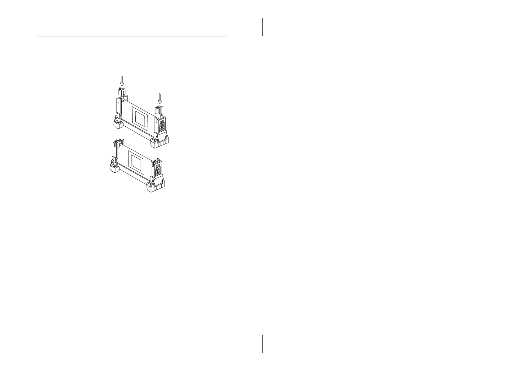
Step 4:
After installing CPU card into the Holder retention, then
push the retention locker downward to secure the CPU card
as indicated in the following 2 drawings.
CPU Speed Setting
This mainboard provides CPU Plug and Play technology,
so that there is no need to do the CPU jumper setting. Enter
the BIOS Setup and select CPU Plug and Play Setup.
Choose the correct CPU speed to match your CPU installed.
However, if you need to change a CPU, follow the below
steps:
1. Power off system and unplug the power core.
2. Install a new CPU to Slot1.
3. Clear CMOS RAM (see Jumper Settings) then power
on the system.
4. After power on the system, then enter the BIOS Setup
to set the new CPU speed.
Note: If the CPU speed is set incorrectly and fails to boot
up the system, then repeat steps 1, 3, 4 again.
Chapter 2
Page 15

Hardware Configuration
Memory Installation
The mainboard lets you add up to 768MB of system memory
through 3 DIMM sockets on the board, that is divided into
3 banks: Bank 0, Bank 1, and Bank 2. Supports the following
memory configuration.
Bank Memory Module
Bank 0
DIMM1 4MB, 8MB, 16MB, 32MB, 64MB, 128MB, 256MB
Bank 1
DIMM2 4MB, 8MB, 16MB, 32MB, 64MB, 128MB, 256MB
Bank 2
DIMM3 4MB, 8MB, 16MB, 32MB, 64MB, 128MB, 256MB
Total System Memory = Bank 0 + Bank 1 + Bank 2
Notes: The speed of SDRAM modules have to be faster than 12ns("-12"
parts). While 100 MHz clock speed used, the speed of SDRAM
modules should meet the PC100 SDRAM specification (8ns or "-8"
SDRAM at least).
11
Page 16

12
Jumper Settings
J12 - CMOS Clear Selector
There is a battery on the mainboard, that is used to retain the
system configuration in CMOS RAM.
Chapter 2
Description
Normal Mode
Clear CMOS
Setting
1
1
(while shipping)
Note: 1. Make sure the jumper is set to Normal Mode before use.
2. Once you need to clear the CMOS, make sure your system
is truned off and the power cord is unplugged.
J13 – Keyboard Power On Selector
This jumper is designed for Keyboard Power On function.
Description
Disabled
(default)
Enabled
Note: Make sure that the system power can provide 720mAon
+5VSB(+5V Standby) signal.
1
Setting
1
1
J13
1
J12
Page 17

Hardware Configuration
ATX Functions & Connectors
This mainboard support ATX power and ACPI functions,
these functions and connectors describe below.
Please refer to the Power Management Setup for more
settings of them.
Software Power-Off
Follow the steps below to use the "Software Power-Off
Control" function in Windows 95/98.
1. Click the START button on the Windows 95/98 task bar.
2. Select Shut Down The Computer to turn off the
computer. The message "It is now safe to turn off your
computer." will not be shown when using this function.
Modem Ring Power Up
While in Soft-off/Suspend state, if an external modem
ring-up signal occurs, the system wakes up and can be
remotely accessed. Make sure that the COM Ports option
is set to activity.
Alarm Wake Up
If you want to auto boot the system at a certain time. Please
set the Power Up by Alarm option to Enabled and the
options of Alarm time properly in BIOS Setup.
13
Keyboard Power On
Press the hot key to power on the system by keyboard.
Please enter BIOS Setup to set the KB Power On Function
and set the Keyboard Power On jumper (see Jumper
Settings).
Page 18

14
Chapter 2
PWR1 - ATX Power Connector
Connect the ATX power supply to this connector that
provide all power for the mainboard.
J10(21,22) - Power Button/Suspend Switch
Connector
Attach the ATX Power Button cable to this connector.
When the system is off, push the power button to turn the
system on.
When the system is on, push the power button rapidly to
switch the system to the Suspend mode, and, by push and
hold the button for more than 4 seconds to turn the system
completely off.
When the system is in the Suspend mode, push the power
button rapidly to turn the system on.
J4 - Wake On LAN Connector
While in Suspend state, if an external LAN signal occurs,
the system wakes up and can be accessed with the LAN
card.
PWR1
J4
3 Act Hi
2 GND
1 5V SB
pin 21,22 --- Power Button
2 1
J10
22 21
Page 19

Hardware Configuration
Connectors
Attach system components and case devices to the
mainboard via the mainboard connectors. A description of
each connector follows. See figure 2-1 for the location of
the connectors on the mainboard.
Note: Make sure that the power is turned off before making any
connection to the board.
External Connectors Location
There are some external connectors on the mainboard that
will be used directly without any bracket, interface or
adapter. As following drawing, that contains PS/2 Mouse,
PS/2 Keyboard, 2 USB, Parallel port, COM1 port, VGA
port, Game port, Sound port connectors.
A description of Sound and Game is in the Onboard Sound
section.
15
PS/2 Mouse
(6-pin Female)
PS/2 Keyboard
(6-pin Female)
USB
Parallel(printer) port (25-pin Female) Game
COM1 VGA
Serial Port
(9-pin Male)
VGA Port
(15-pin Female)
Line out
Line in
/Rear
Sound Port
Side View
MIC
Page 20

16
Chapter 2
FDC1 - Floppy Disk Port
The mainboard provides a standard floppy disk port that
supports two 360K/720K/1.2M/1.44M/2.88M floppy disks.
IDE1/IDE2 - Primary/Secondary IDE Ports
The mainboard has a 32-bit Enhanced PCI IDE Controller
that provides two IDE port and supports PIO mode, PCI
Bus Master and Ultra DMA 33/66 operation modes.
Connect IDE ports to IDE devices, one IDE port can
supports two devices that one set to Master and other one
set to Slave. You can connect up to four IDE devices.
FAN1,FAN2 - Fan Power Connectors
These connectors support CPU and chassis cooling fan with
+12V.
1
FDC1
FAN1
FAN2
1 Sense
2 +12V
3 GND
1 Sense
2 +12V
3 GND
1
1
IDE1
IDE2
Page 21

Hardware Configuration
IR - InfraRed Connector
The mainboard provides the 5-pin Infrared connector for
IR devices. You must configure the setting of IR device
through the Peripheral Setup.
17
Pin
IR
Signal
1
2
3
4
5
1
VCC
IRRXH
IRRXL
GND
IRTX
Page 22

18
Chapter 2
J10 - Case Connectors
The case connectors contain Speaker, Power LED, Keylock,
HDD LED, Reset Switch, ACPI LED and Power Button.
See below drawing for the location on the mainboard.
2 1
J10
22 21
pin1,3,5,7 - Speaker
pin2,4,6 - Power LED
pin8,10 - Keylock
pin15,16 - HDD LED
pin17,18 - Reset Switch
pin19,20 - ACPI LED
pin21,22 - Power Button
(refer to ATX Functions & Connectors)
Page 23

Hardware Configuration
Onboard PCI Sound
Sound and Game(on the External Connectors)
The board provides Line-In/Rear, MIC(Microphone), LineOut(Speaker) signals for audio jack and Game port(which
is also used for the Joystick/MIDI port) signals.
CD1/CD2 - Analog Audio from CD-ROM
Connect "AUDIO" output of the CD-ROM drive to these
connectors. Panasonic compatible CD-ROM should
connect to CD2 (pin signals assignment is G-L-G-R), Sony
compatible CD-ROM should connect to CD1 (pin signals
assignment is L-G-G-R).
Side View
Line out
Game port
Line in
/Rear
Sound port
19
MIC
CD2
1
CD1
Page 24

20
Chapter 2
J16 – Digital Audio Connector
Connect this connector to the Digital Audio ribbon cable/
bracket that contains 3 jacks for Aux IN, SPDIF IN and
SPDIF OUT device. Aux IN is used for the second Line-in
port. SPDIF IN is used for input the external digital audio.
Connect SPDIF OUT to the AC3 Audio Amplifier or MiniDisk to play, and set the following jumper to select 5V or
0.5V signal level for used device.
J6 – SPDIF OUT Signal Level Selector
Description
J6
5V
0.5V
(default)
J17 – Internal SPDIF IN Connector
Use SPDIF/IN cable to connect to the “DIGITAL AUDIO”
port for the CD-ROM. This will give you non-distorted
digital audio from CD-ROM.
J6
J6
J16
1
J17
Notice that you should avoid to use the SPDIF IN jack and
the internal SPDIF IN connector simultaneously. i.e. if one
of them is connected, you should unplug the other one.
J16
1
J17
Page 25

Hardware Configuration 21
Notice for PCI Sound application
1. Before you install PCI Sound drivers, make sure
your operating system has already been installed.
Otherwise the PCI Sound might be detect as "Other
Device" by the device manager.
2. After the drivers installed, if you wants to use Software
Wave-Table drivers as MIDI output device. Select
MULTIMEDIA icon in the CONTROL PANEL. Select
MIDI page, and click on the "C-media SoftMidi
Synthesis(Win98)/Driver(Win95)" then click "OK" to
confirm.
3. A Windows application named Audio Rack is provided
within PCI Sound drivers, will give you control
over all audio functions through a user's interface. This
is as simple to use a home stereo system. We
recommended that users use the System Mixer in the
Audio Rack to control the volume, select recording
device to record.
4. If the Midi port is used as the control interface, you
need to select MULTIMEDIA icon in the CONTROL
PANEL. Select MIDI page, click on the "CM8338
MPU-401"(Win98) or the "CMI8338/C3DX PCI
Audio External MIDI port"(Win95) then click "OK"
to confirm.
5. Please refer to the attached CD for more information
on PCI Sound.
Page 26

22 Chapter 2
The Four Speakers System
Onboard Sound provides 2 wave channels (front/rear),
known as the 4 speakers system. When application
programs via DirectSound® 3D or A3D® interface locate
the sound sources to the listener's back, the two rear
speakers will work to enhance the rear audio positional
effect, so as to complement the insufficiency of using only
two front speakers to emulate the audio effect. The
following is the hardware installation and the software
setups:
1. Speaker Installation
Connect the front pair speakers to the Line-out jack on the
Sound port, and then, connect rear pair speakers to Line-in/
Rear jack. The original Line-in can be moved to Aux-in.
2. Speaker Position
Set up your speakers similar to the following figure to get
the best audio result.
3. Mixer Setup
When user was setup the PCI Audio Application, there is a
4 speakers option in the Volume Control of the Mixer. Click
on the 4 SPK icon to enable this option. This means that the
rear speakers are connected to Line-in/Rear jack. However,
in order to avoid hardware conflicts, DO NOT enable this
option when Line-in/Rear jack is connected to other external
Line-in sources. Turn on/off the output of the front speakers
and adjust the volume of speakers to the same volume for
the rear speakers.
4. Demo
Execute the "Helicopter" demo within the C3D HRTF
Positional Audio Demos of the PCI Audio Application.
When the helicopter flies behind you, it means that the rear
speakers are working properly.
Page 27

Hardware Configuration
23
Line-out
(Sound Port)
Line-in/Rear
Speaker
Speaker
Front Speakers
Rear Speakers
Speaker
Monitor
Speaker
A picture on the 4 speakers application
Onboard VGA
The mainboard onboard SiS 6326 chip provides high
performance 64-bit 3D AGP Graphics Accelertor with 8MB
frame buffer share from system memory.
It supports following features,
- AGP 2.0 compliant configuration
- 133MHz AGP operation
- MPEG-2 ISO/IEC 13818-2 MP@ML and MPEG-1 ISO/
IEC 11172-2 standards
- two 196 x 64 video line buffers for MPEG video playback
- 175MHz pixel clock
- super high resolution graphics modes up to 1600 x 1200
- virtual screen up to 2048 x 2048
- 80/132 columns text modes
Page 28

Chapter 4
Software Driver
The support software CD-ROM came with the
package is free of charge. It includes all our
products’ drivers.
Please first go to the CD-ROM to view
"readme.txt" for each software program location.
 Loading...