

Page 1

Mainboard User’s Manual
This publication, photographs, illustrations and software are under
the protection of international copyright laws and all rights
reserved. It does not allow any reproduction of this manual, content
and any materials contained herein without the written consent of
the authentic manufacturer.
The information in this manual is subject to change without notice.
The manufacturer does neither represent nor warrant the contents
hereof; and specifically disclaims any implied warranties of
merchantability or fitness for any particular purpose. Furthermore,
the manufacturer reserves the right to revise and change this
publication from time to time, without the obligation of notifying
any person of such revision or changes.
Trademarks
IBM, VGA, and PS/2 are registered trademarks of International
Business Machines.
Intel, Pentium, Pentium-II, Pentium-III, Pentium-IV, MMX,
Celeron and Tualatin are registered trademarks of Intel Corporation.
Microsoft, MS-DOS and Windows 95/98/NT/2000 are registered
trademarks of Microsoft Corporation.
PC-cillin is a trademark of Trend Micro Inc.
Award is a trademark of Award Software Inc.
A3D is a registered trademark of Aureal Inc.
SuperVoice is a registered trademark of Pacific Image
Communications Inc.
MediaRing Talk is a registered trademark of MediaRing Inc.
3Deep is a registered trademark of E-Color Inc.
Other names used in this publication may be trademarks and are
acknowledged.
Copyright © 2001
All Rights Reserved
MS7188D Series, V5.2
V8601T/December 2001
Page 2

Mainboard User’s Manual
II
Page 3

Mainboard User’s Manual
Table of Contents
Trademarks..............................................................................I
Chapter 1......................................................................................... 1
Introduction................................................................................. 1
Key Features...........................................................................2
Package Contents.................................................................... 4
Static Electricity Precautions..................................................5
Pre-Installation Inspection...................................................... 5
Chapter 2......................................................................................... 7
Mainboard Installation................................................................7
Mainboard Components.......................................................... 8
I/O Ports.................................................................................. 9
Install A CPU.......................................................................... 9
Install Memory...................................................................... 11
Setting Jumper Switches....................................................... 12
Install the Mainboard............................................................ 15
Optional Extension Brackets................................................. 17
Install Other Devices ............................................................ 18
Expansion Slots..................................................................... 20
Chapter 3....................................................................................... 23
BIOS Setup Utility....................................................................23
Introduction........................................................................... 23
Running the Setup Utility.....................................................24
Standard CMOS Features Page............................................. 25
Advanced BIOS Features Page............................................. 26
Advanced Chipset Features Page.......................................... 28
Integrated Peripherals Page...................................................30
Power Management Setup Page............................................32
PnP/PCI Configurations Page............................................... 34
Hardware Monitor Page........................................................ 36
Frequency/Voltage Control................................................... 37
Load BestPerf. Defaults........................................................ 38
Load Optimized Defaults...................................................... 38
Set Password......................................................................... 38
Save & Exit Setup................................................................. 39
Exit Without Saving.............................................................. 39
Using the Mainboard Software..................................................... 41
About the Software CD-ROM................................................... 41
Drivers Installation.................................................................... 42
III
Page 4

Mainboard User’s Manual
Utility Software Reference........................................................ 43
IV
Page 5

1: Introduction
Chapter 1
Introduction
This mainboard has a Socket-370 processor socket for Intel
FCPGA Celeron, FCPGA Pentium III or Tualatin/Tualatin
Celeron processors. You can install any one of these processors
on this mainboard.
This mainboard supports front-side bus speeds of 66MHz,
100MHz or 133MHz.
This mainboard uses the VIA 8601T chipset to integrate a 3D
Graphics Accelerator and Ultra DMA 33/66/100 function. The
mainboard has a built-in AC97 Codec, and an AMR (Audio
Modem Riser) slot to support Audio and Modem application. In
addition, this mainboard has an extended set of ATX I/O Ports
including PS/2 keyboard and mouse ports, two USB ports, a
parallel port, a VGA port, a serial port, a game port and audio ports.
An extra USB header gives you the option of connecting two more
USB ports.
This mainboard has all the features you need to develop a powerful
multimedia workstation. The board is Micro ATX size and has a
power connector for an ATX power supply.
1
Page 6

Mainboard User’s Manual
Key Features
The key features of this mainboard include:
Socket-370 Processor Support
♦ Supports FCPGA Celeron, FCPGA Pentium III and
Tualatin/Tualatin Celeron CPUs
♦ Supports 66MHz, 100MHz or 133MHz Front-Side Bus
All processors are automatically configured using firmware and a
synchronous/asynchronous Host/DRAM Clock Scheme.
Note : Do not support PPGA Celeron CPU. Do not try to install
PPGA Celeron processor in Socket-370.
Memory Support
♦ Two DIMM slots for 168-pin SDRAM memory modules
♦ Support for 100/133 MHz memory bus
♦ Maximum installed memory is 2 x 512MB = 1GB
Expansion Slots
♦ One AMR slot for a special audio/modem riser card
♦ Three 32-bit PCI slots for PCI 2.2-compliant bus interface.
♦ One 8/16-bit ISA slot.
Onboard IDE channels
♦ Primary and Secondary PCI IDE channels
♦ Support for PIO modes, Bus Mastering and Ultra DMA
33/66/100 modes
Power Supply and Power Management
♦ ATX power supply connector
♦ ACPI and previous PMU support, suspend switch
♦ Supports Wake on LAN and Wake on Alarm
Built-in Graphics System
♦ Onboard 64-bit 2D/3D graphic engine and Video
Accelerator with advanced DVD video
♦ 2 to 8 MB frame buffer use system memory
♦ Supports high resolutions up to 1600x1200
2
Page 7

1: Introduction
AC97 Codec
♦ Compliant AC97 2.1 specification
♦ Supports 18-bit ADC (Analog Digital Converter) and DAC
(Digital Analog Converter) as well as 18-bit stereo fullduplex codec
Onboard I/O Ports
♦ Provides PC99 Color Connectors for easy peripheral device
connections
♦ Floppy disk drive connector with 1Mb/s transfer rate
♦ One serial ports with 16550-compatible fast UART
♦ One parallel port with ECP and EPP support
♦ Two USB ports, and optional two USB ports module
♦ Two PS/2 ports for keyboard and mouse
♦ One infrared port connector for optional module
Hardware Monitoring
♦ Built-in hardware monitoring for CPU & System
temperatures, fan speeds and mainboard voltages
Onboard Flash ROM
♦ Automatic board configuration support Plug and Play of
peripheral devices and expansion cards
Bundled Software
♦ PC-Cillin2000 provides automatic virus protection under
Windows 95/98/NT/2000
♦ SuperVoice is data, fax and voice communicat ion softwar e
♦ MediaRing Talk provides PC to PC or PC to Phone
internet phone communication
♦ 3Deep delivers the precise imagery and displays accurate
color in your monitor
♦ WinDVD2000 is a DVD playback application (optional)
Dimensions
♦ Micro ATX form factor (24.4cm x 19cm)
3
Page 8

Mainboard User’s Manual
Package Contents
Your mainboard package ships with the following items:
!
The mainboard
!
This User’s Guide
!
1 UDMA/66 IDE cable
!
1 Floppy disk drive cable
!
Support software on CD-ROM disk
Optional Accessories
You can purchase the following optional accessories for this
mainboard.
!
Extended USB module
4
Page 9

1: Introduction
Static Electricity Precautions
Static electricity could damage components on this mainboard.
Take the following precautions while unpacking this mainboard
and installing it in a system.
1. Don’t take this mainboard and components out of their original
static-proof package until you are ready to install them.
2. While installing, please wear a grounded wrist strap if possible.
If you don’t have a wrist strap, discharge static electricity by
touching the bare metal of the system chassis.
3. Carefully hold this mainboard by its edges. Do not touch those
components unless it is absolutely necessary. Put this
mainboard on the top of static-protection package with
component side facing up while installing.
Pre-Installation Inspection
1. Inspect this mainboard whether there are any damages to
components and connectors on the board.
2. If you suspect this mainboard has been damaged, do not
connect power to the system. Contact your mainboard vendor
about those damages.
5
Page 10

Mainboard User’s Manual
6
Page 11

2: Mainboard Installation
Chapter 2
Mainboard Installation
To install this mainboard in a system, please follow thes e
instructions in this chapter:
!
Identify the mainboard components
!
Install a CPU
!
Install one or more system memory modules
!
Make sure all jumpers and switches are set correctly
!
Install this mainboard in a system chassis (case)
!
Connect any extension brackets or cables to connecting
headers on the mainboard
!
Install other devices and make the appropriate connections to
the mainboard connecting headers.
Note:
1. Before installing this mainboard, make sure the jumper BAT1
is set to Normal setting. See this chapter for information about
locating jumper BAT1 and the setting options.
2. Never connect power to the system while installing; otherwise,
it may damage the mainboard.
7
Page 12
Mainboard User’s Manual
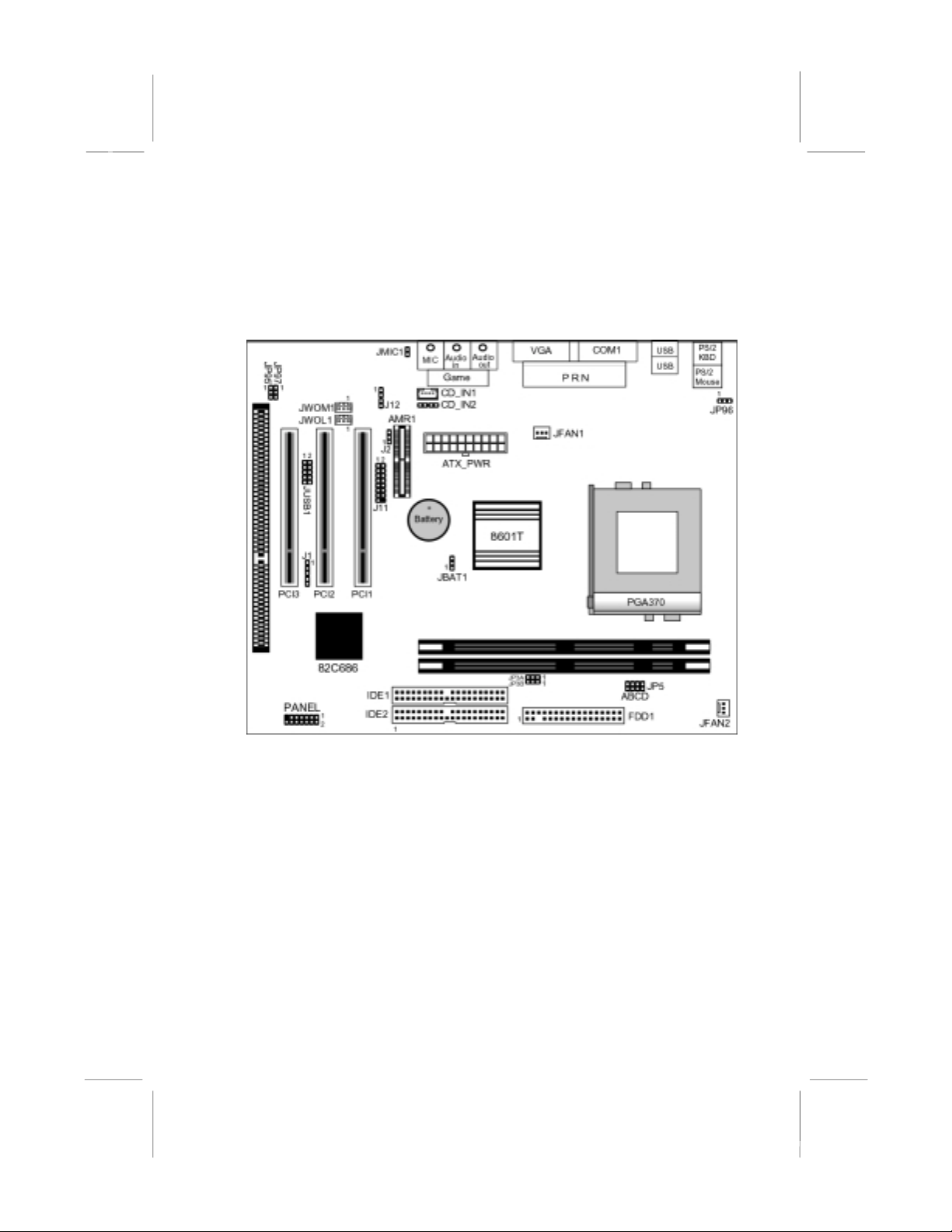
Mainboard Components
This diagram helps you identify major components on this
mainboard.
Note: Any jumpers on your mainboard but not appearing in
this illustration are for testing only.
8
Page 13

2: Mainboard Installation
I/O Ports
This illustration shown below is a side view of the built-in I/O
ports on this mainboard.
PS/2 Mouse
Parallel Port
VGA Port
Game/MIDI Port
PS/2 Keyboard
USB Ports
Serial Port COM1/3
Line-Out Jack
Line-In Jack
Microphon e Jac k
Install A CPU
This mainboard has a Socket 370 supporting FCPGA Celeron,
FCPGA Pentium III and Tualatin/Tualatin Celeron processors.
Do not support PPGA Celeron processor.
To ensure reliability, ensure that your processor has a
heatsink/cooling fan assembly.
Do not try to install a Socket 7 processor in the Socket-370. A
Socket 7 processor such as the Pentium-MMX, or the AMD K5/K6
does not fit in the Socket 370. Do not try to install PPGA
Celeron processor in Socket-370.
The following list notes the processors that are currently supported
by this mainboard.
FCPGA Celeron: 300~966 MHz, FSB: 66 MHz
FCPGA Pentium III: 500~1130MHz, FSB: 100MHz, 133MHz
Tualatin/Tualatin Celeron : up to 1.2GHz, FSB: 100MHz
9
Page 14

Mainboard User’s Manual
Installing a Socket-370 Processor
Install a processor into the ZIF (Zero Insertion Force) Socket-370
on the mainboard.
1. Locate the Socket-370 and JFAN1. Pull the locking lever out
slightly from the socket and raise it to the upright position.
10
Page 15
2: Mainboard Installation
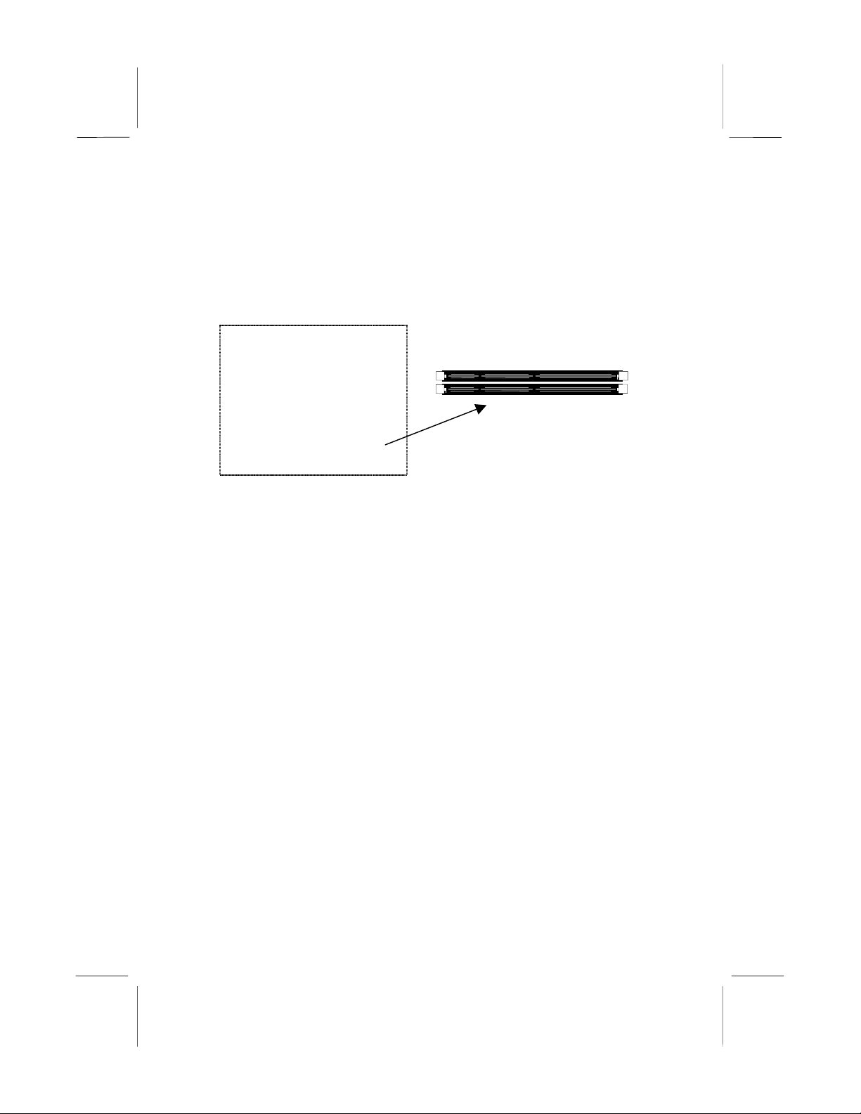
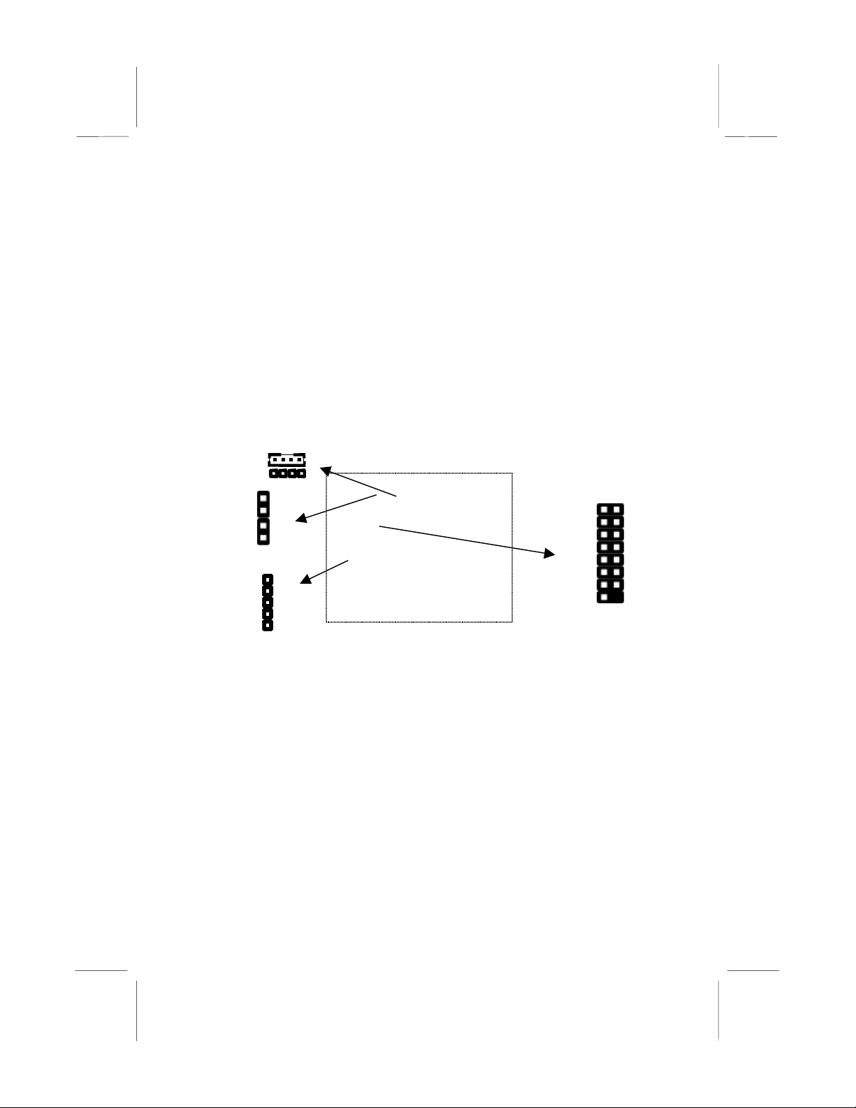
Install Memory
This mainboard has two DIMM sockets for system memory
modules. You must install at least one memory module in order to
work out this mainboard.
DIMM2
DIMM1
For this mainboard, you must use 168-pin, 3.3V unbuffered PC100
or PC133 SDRAM memory modules. You can install any size
memory module from 32 MB to 512 MB, so the maximum
memory size is 2 x 512 MB = 1 GB.
Edge connectors on the memory modules have cut outs coinciding
with spacers in the DIMM sockets that memory modules can only
be installed in the correct orientation.
To install a module, push the retaining latches at either end of the
socket outwards. Position the memory module correctly and insert
it into the DIMM socket. Press the module down into the socket so
that the retaining latches rotate up and secure the module in place
by fitting into notches on the edge of the module.
Page 16
Mainboard User’s Manual
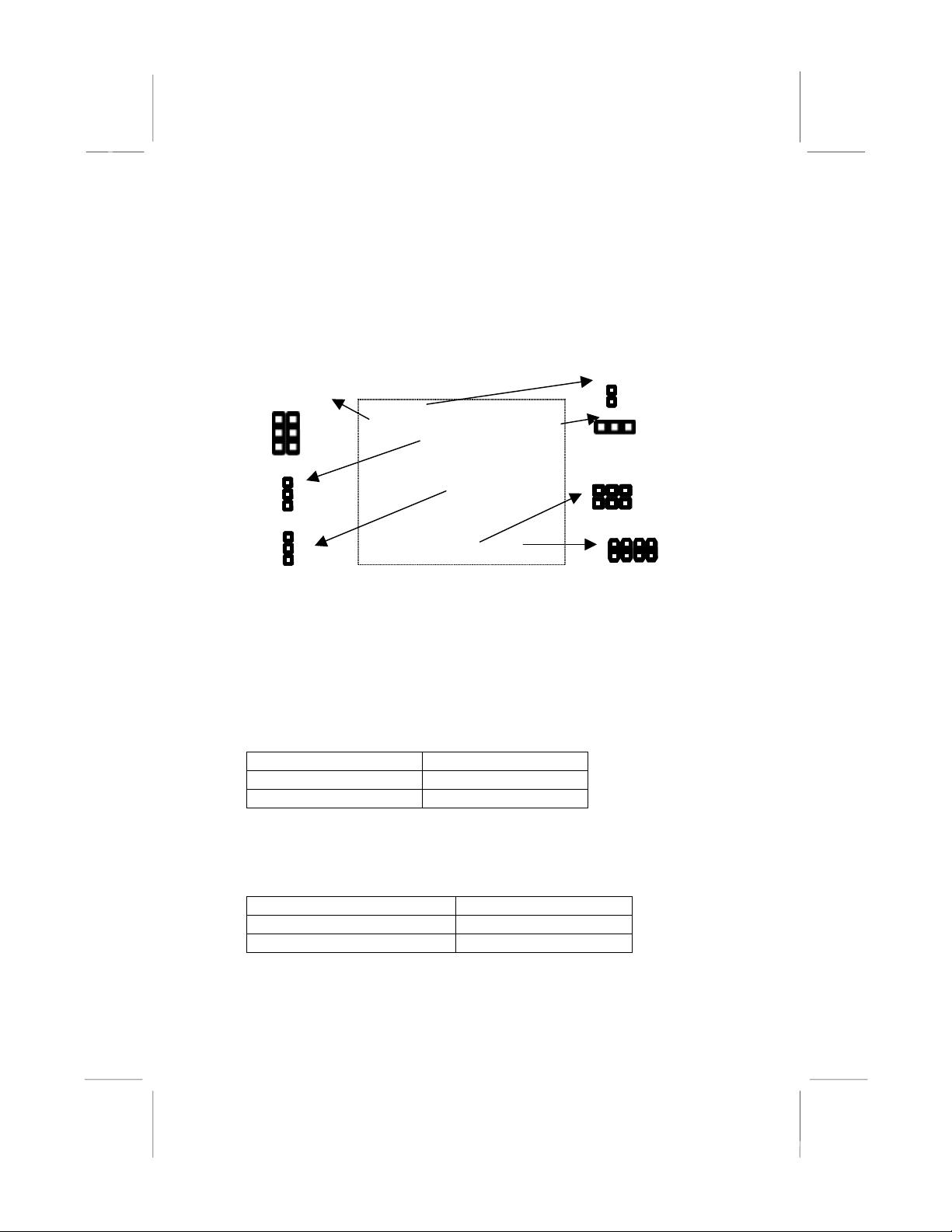
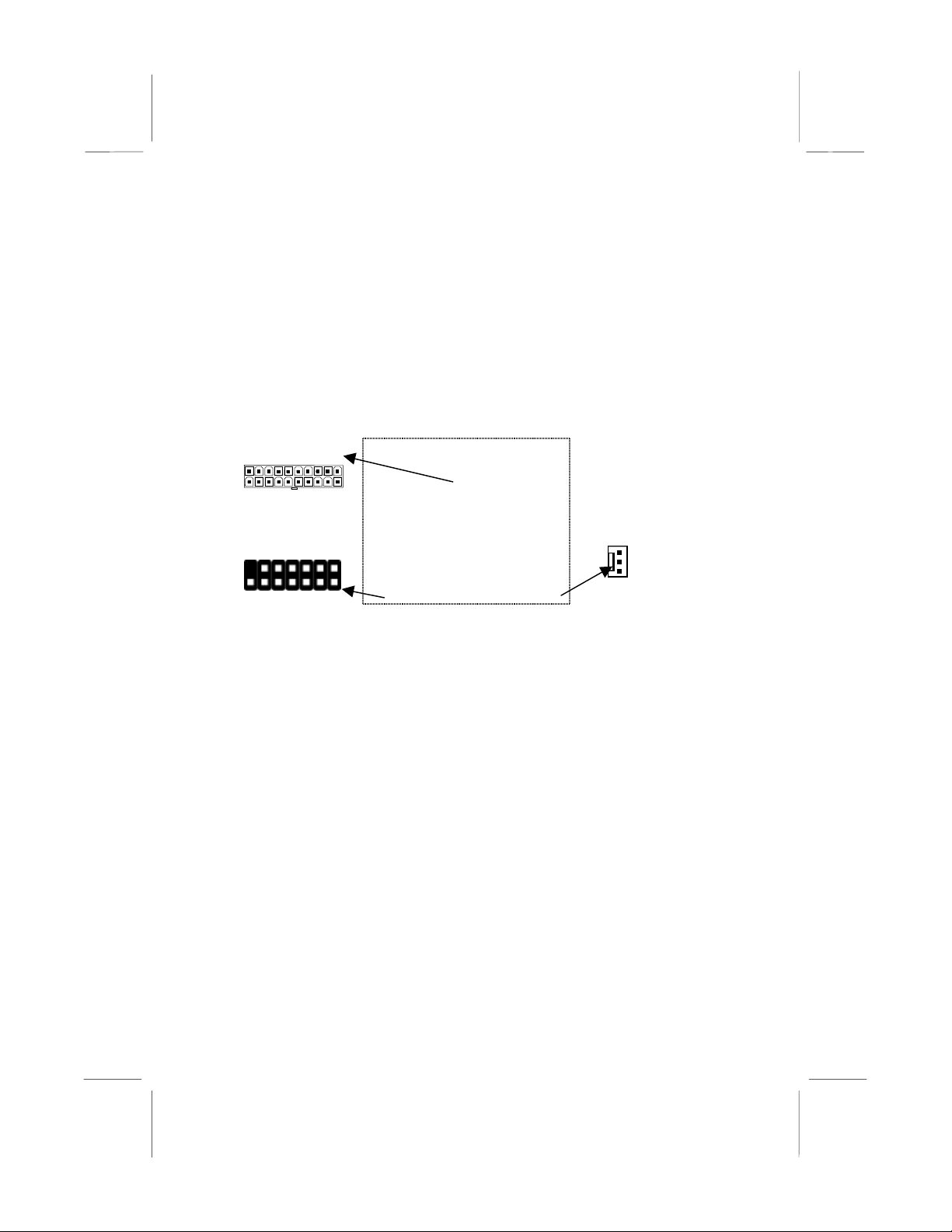
Setting Jumper Switches
Jumpers are sets of pins connected together with caps. Jumper caps
change the way of mainboard’s operation by changing the
electronic circuits on the mainboard. If a jumper cap connects two
pins, we say those pins are SHORT; if the cap is removed, they are
OPEN.
JMIC1
1 1
JP97JP95
1
JP96
J2
1
1
JBAT1
1
1
JP3A
JP3B
A B C D
JP5
Jumper JBAT1: Clear CMOS Memory
This jumper is to clear the contents of CMOS memory. You may
need to clear the CMOS memory if the settings in the Setup Utility
are incorrect that prevents your mainboard from operating. To clear
the CMOS memory, disconnect all the power cables from the
mainboard and then move the jumper cap into the CLEAR setting
for a few seconds.
Function Jumper Setting
Normal Operation Short Pins 1-2
Clear CMOS Memory Short Pins 2-3
Jumper J2: Codec Selector
This jumper is to select the onboard audio codec or Audio Modem
Riser (AMR) slot.
Function Jumper Setting
Primary codec onboard Short Pins 1-2
Primary Codec on AMR slot Short Pins 2-3
2
Page 17
2: Mainboard Installation
Jumper JP3: CPU Frequency Selectors
This jumper consists of two sets of 3-pin jumpers JP3-A and JP3-B.
This jumper is to select the frequency of the installed CPU.
Frequency 66 MHz 100 MHz 105 MHz 133 MHz
JP3-A
JP3-B
2-3 2-3 1-2 1-2
2-3 1-2 2-3 1-2
Jumper JP5: CPU Multiplier Selectors
This jumper consists of four sets of 2-pin jumpers JP5-D, JP5-C,
JP5-B and JP5-A. This jumper is to select the mult ipl ier of the
installed CPU.
CPU Multiplier Selector: JP5
Multiplier 2.0 2.5 3.0 3.5 4.0 4.5 5.0
JP5-D
JP5-C
JP5-B
JP5-A
short short short short short Short short
short open short open short Open short
short short open open short Short open
short short short short open Open open
CPU Multiplier Selector: JP5
Multiplier 5.5 6.0 6.5 7.0 7.5 8.0 8.5+
JP5-D
JP5-C
JP5-B
JP5-A
short open open open open Open open
open short open short open Short open
open short short open open Short open
open short short short short Open open
Note: The CPU speed is equal to the CPU Frequency x the
CPU Multiplier.
Jumper JP95: BIOS Protect
This jumper is to make the BIOS read-only.
Function Jumper Setting
Enable(read-only) Short Pins 1-2
Disable Short Pins 2-3
3
Page 18

Mainboard User’s Manual
Jumper JP96: Keyboard Power On
This jumper enables any keyboard activity to power up a system
previously in a standby or sleep state.
Function Jumper Setting
+5V Short Pins 1-2
+5V SB Short Pins 2-3
Jumper JP97: Flash ROM Voltage
This jumper enables to select voltage of flash ROM.
Function Jumper Setting
+5V Short Pins 1-2
+3.3V Short Pins 2-3
Jumper JMIC1: Microphone-Out Selector
This jumper selects the Microphone-Out to the back-oriented
Microphone jack or the front-orien ted Mic roph one heade r.
Function Jumper Setting
Back-oriented MIC jack Short Pins 1-2
Front-oriented MIC header Open Pins 1-2
4
Page 19
2: Mainboard Installation
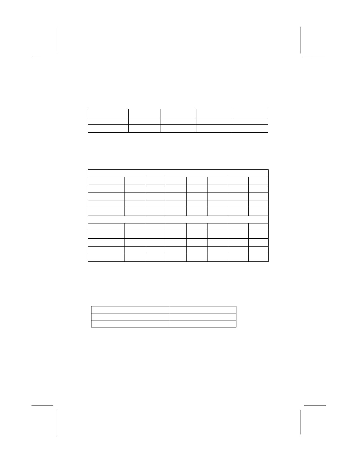
Install the Mainboard
Install the mainboard in a system chassis (case). The board is an
ATX size mainboard with a twin-tier of I/O ports. Make sure your
case has an I/O cover plate that matches the ports on this
mainboard.
Install the mainboard in a case. Follow these instructions of the
case manufacturer to use the hardware and intern al m ountin g
points on the chassis.
ATX
PANEL
1
JFAN2
Connect the power connector from the power supply to the ATX
connector on the mainboard.
If there is a cooling fan installed in the system chassis, connect the
cable from the cooling fan to the JFAN2 fan power connector on
the mainboard.
Connect case switches and indicator LEDs respectively to the
PANEL switch and LED connector header.
5
Page 20
Mainboard User’s Manual
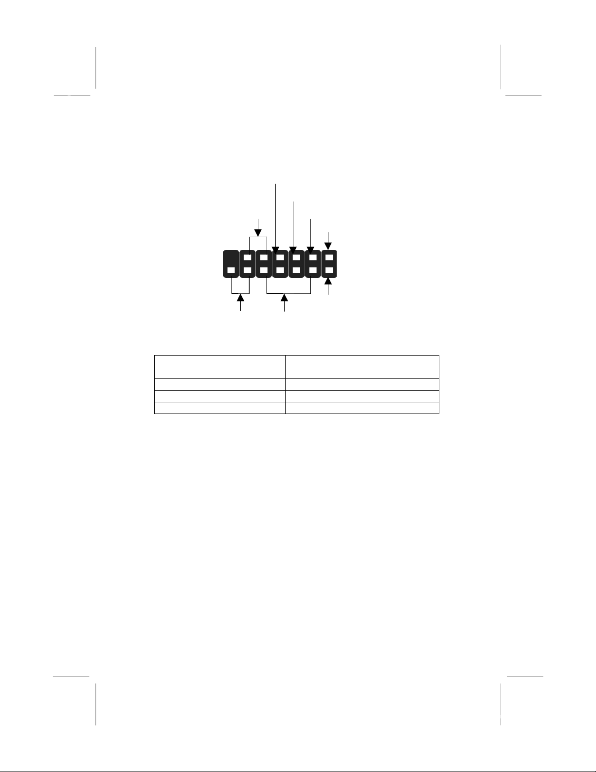
This illustration below gives you a guide of the header’s pin
assignment.
Power LED(+)
Power LED(-) Green
Power Button Pins 9-11
13
14
Reset Switch
Pins 12-14
Speaker Pins
4-6-8-10
Power LED(-) Yellow
HDD LED(+)
1
2
HDD LED(-)
System State Dual Color POWER LED State
S0 Steady Green
S1 Green Blinking
S3 Steady Yellow
S4/S5 Off
6
Page 21
2: Mainboard Installation
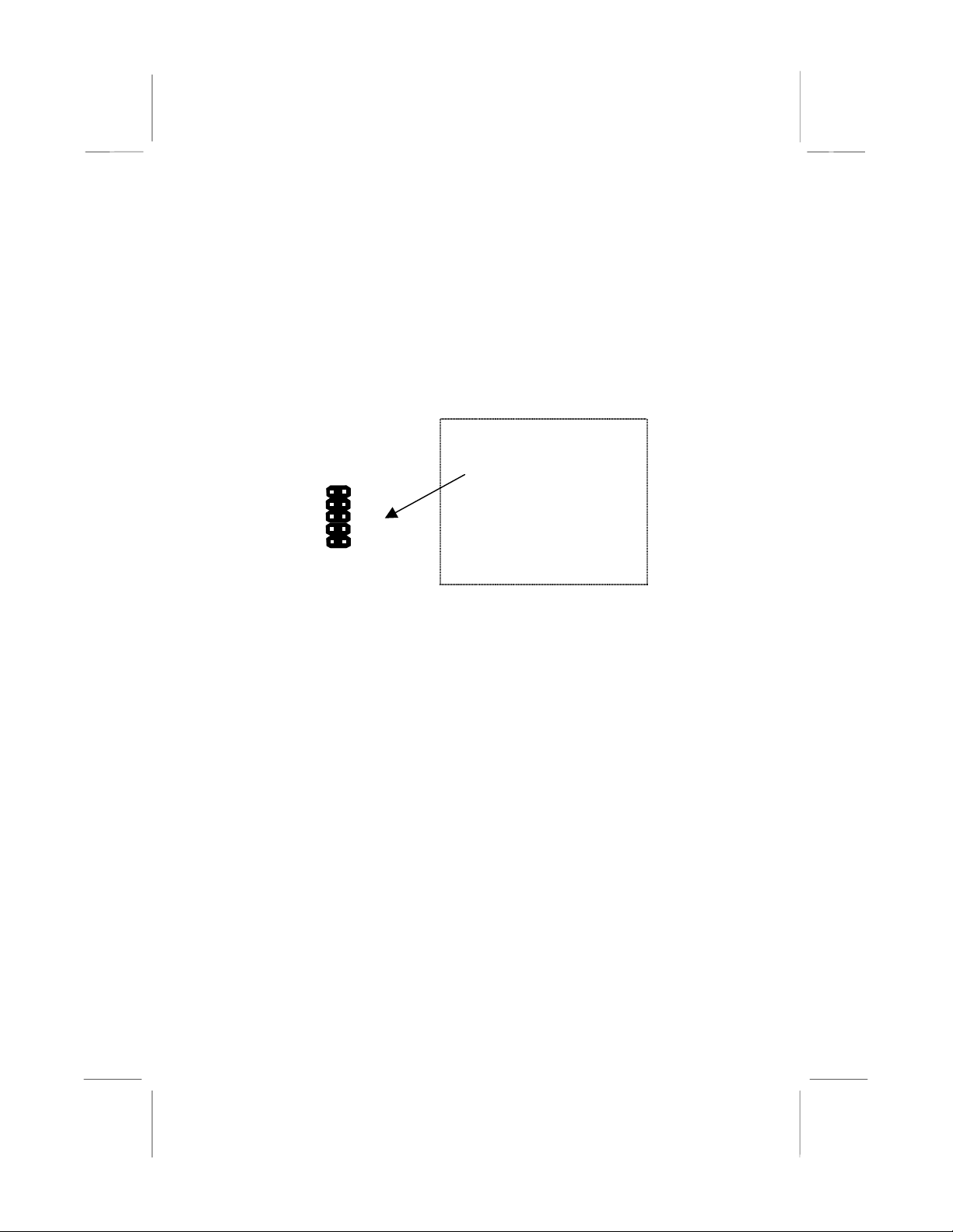
Optional Extension Brackets
You also have a USB module extension bracket for this mainboard.
Install it by following these steps below.
Extended USB Module
This module bracket has two USB ports for more USB devices
(USB port 3-4).
JUSB1
VCC
UV-
UV+
GND
GND
1. Locate the USB1 header on the mainboard.
2. Plug the bracket cable onto the header.
3. In the system chassis, remove a slot cover from one of the
expansion slots, install the extens ion brack et in to that emptied
slot, and then screw this bracket firmly to that slot.
GND
NC
UV+
UVVCC
7
Page 22
Mainboard User’s Manual
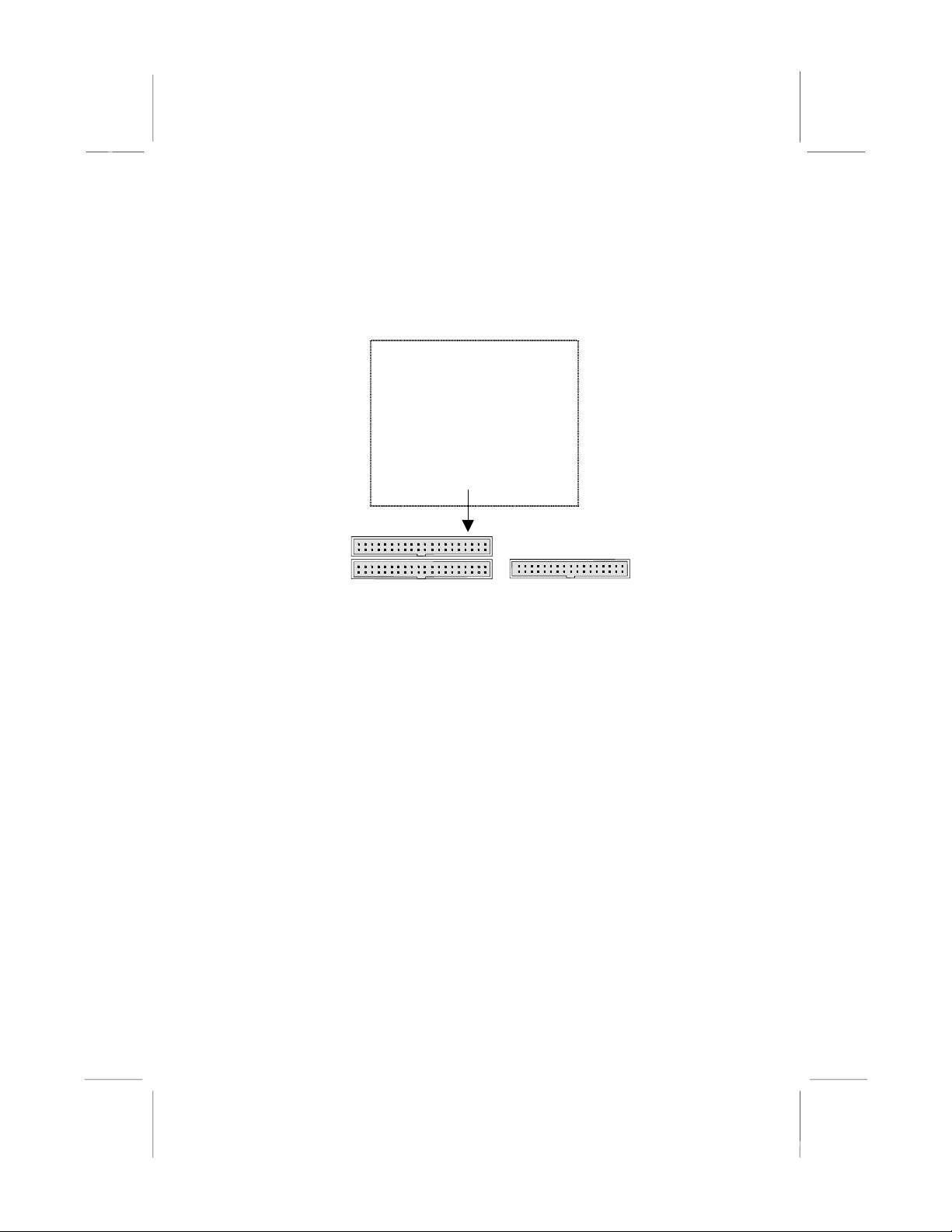
Install Other Devices
Follow these steps below to install and connect other devices in the
system.
IDE1
1
1 1
IDE2
Floppy Disk Drive
The mainboard ships with a floppy disk drive cable that can
support one or two drives. Drives can be 3.5” or 5.25” wide, with
capacities of 360K, 720K, 1.2MB, 1.44MB, or 2.88MB.
Install your drives and connect power from the system power
supply. Use the enclosed cable to connect the drives to the floppy
disk drive header FDD1.
FDD1
IDE Devices
IDE devices include hard disk drives, high-density diskette drives,
and CD-ROM or DVD-ROM drives, among others.
The mainboard ships with an IDE cable that can support one or two
IDE devices. If you connect two devices to one single cable, you
must configure one of the drives as Master and the other as Slave.
The documentation of the IDE device will tell you how to
configure the device as a Master or Slave device. The Master
device connects to the end of the cable.
Install the device(s) and connect power from the system power
supply. Use the enclosed cable to connect the device(s) to the
Primary IDE channel connector IDE1 on the mainboard.
8
Page 23
2: Mainboard Installation
If you want to install more IDE devices, you can purchase a second
IDE cable and connect one or two devices to the Secondary IDE
channel connector IDE2 on the mainboard. If you have two
devices on the cable, one must be Master and another must be
Slave.
Internal Sound Connections
If you have installed a CD-ROM drive or DVD-ROM drive, you
can connect the drive audio cable to the onboard sound system.
On the mainboard, locate the two 4-pin connectors CD_IN1 and
CD_IN2. There are two kinds of connectors for different brands of
CD-ROM drive have different audio cable connectors. Connect the
cable to the appropriate connector.
CD_IN1
CD_IN2
MONO-OUT
1
GND
GND
J12
PHONE-IN
J1-IR Header
VCC
1
NC(CUT)
IRRX
GND
IRTX
LINE OUT R_
FRONT LINE OUT(R)
FRONT LINE OUT(L)
J11-Front Audio Panel
1
GND(A)
GND
+12V
MIC
GND(A)
LINE OUT(L)
GND(A)
GND
NC(CUT)
GND(A)
NC
NC
NC(CUT)
Front Audio Panel
If the front audio panel has a microphone-in jack and/or a speakerout jack, connect the cables from the microphone- in and speakerout jacks to the J11 header on the mainboard. Then set the jumper
JMIC1 to open setting.
Modem In
The Modem In J12 header on the mainboard helps the input/output
of modem audio signals through a microphone jack and/or a
speaker-out jack.
9
Page 24
Mainboard User’s Manual
Infrared Port
You can connect an infrared port to the mainboard. You can
purchase this optional item from the third-party vendors.
1. Locate the infrared port IR header on the mainboard.
2. If you add an infrared port, connect the ribbon cable from the
port to the header, and then secure the port to an appropriate
place in your system chassis.
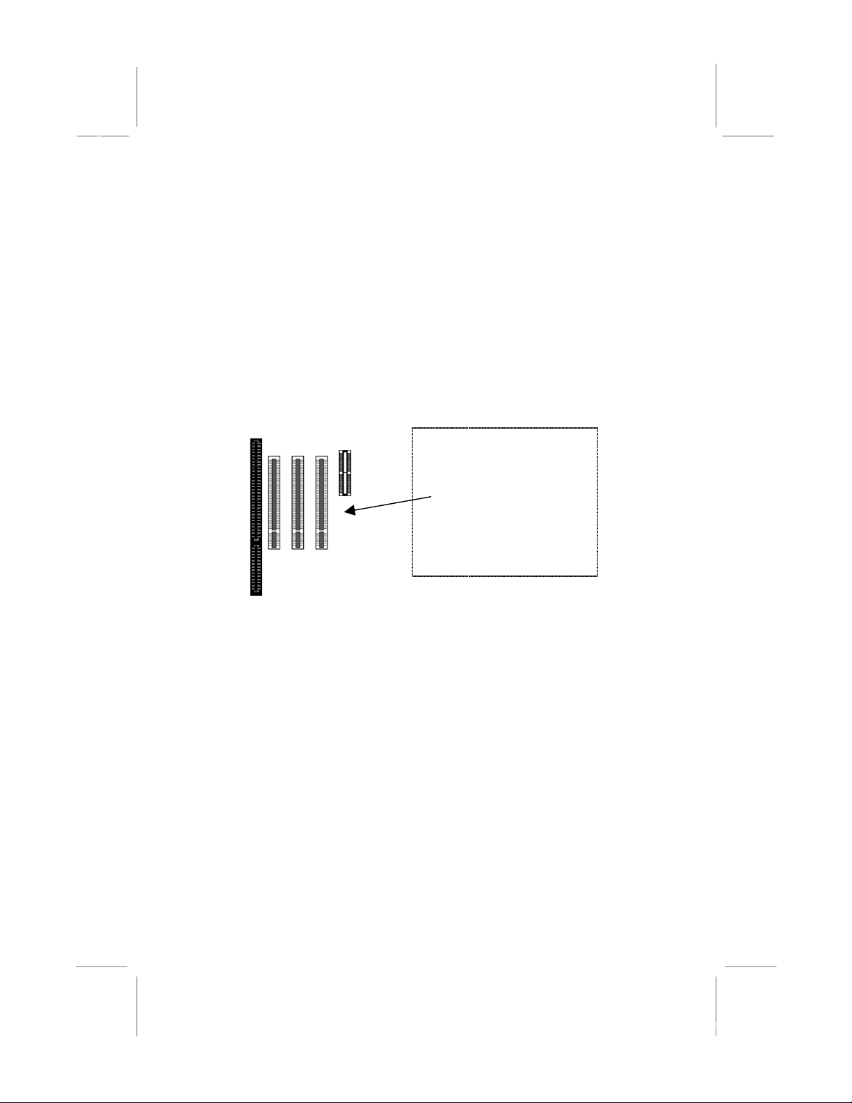
Expansion Slots
This mainboard has three 32-bit PCI expansion slots, one AMR
slot and one 8/16-bit ISA slot.
PCI3 PCI1
PCI2
AMR1
ISA1
Follow these steps below to install a PCI/AMR/ISA expansion card.
1. Locate the AMR, PCI or ISA slots on the mainboard.
2. Remove the slot cover from the system chassis.
3. Insert the edge connector of expansion card into the slot and
press it firmly down into until fully inserted.
4. Secure the expansion card bracket to the system chassis with
that slot cover’s screw.
AMR Slot
The AMR (Audio Modem Riser) slot is an industry standard slot
that allows the installation of a special audio/modem riser card.
Different territories have different regulations regarding the
specifications of a modem card. You can purchase an approved
AMR card in your area and install it directly into the AMR slot.
10
Page 25
2: Mainboard Installation
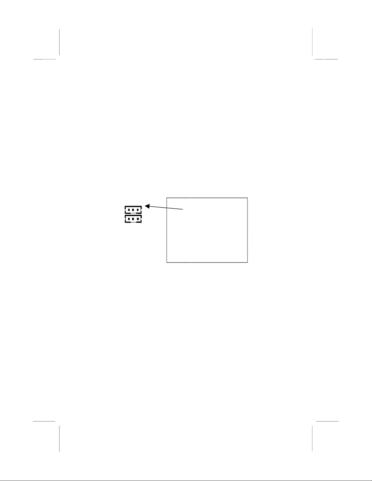
Wake On Modem (JWOM1)
You can configure your system to be powered down by software
and resumed by alarms. If you have installed a fax/modem card,
connect the fax/modem to the Wake On Modem header JWOM1.
You can use the setup utility to program your computer to resume
from a power saving mode whenever there is an incoming call to
the fax/modem.
Wake On LAN (JWOL1)
If you have installed a LAN adapter expansion card, connect the
card to the Wake On LAN connector JWOL1. This allows
incoming traffic to resume the system from a software power down.
You need to enable this feature in the system setup utility.
JWOM1
Header
JWOL1
Header
11
Page 26

Mainboard User’s Manual
12
Page 27

3: BIOS Setup Utility
Chapter 3
BIOS Setup Utility
Introduction
The BIOS Setup Utility records settings and information of your
computer, such as date and time, the type of hardware installed,
and various configuration settings. Your computer applies those
information to initialize all the components when booting up and
basic functions of coordination between system components.
If the Setup Utility configuration is incorrect, it may cause the
system to malfunction. It can even stop your computer booting
properly. If it happens, you can use the clear CMOS jumper to
clear the CMOS memory which has stored the configuration
information; or you can hold down the Page Up key while
rebooting your computer. Holding down the Page Up key also
clears the setup information.
You can run the setup utility and manually change the
configuration. You might need to do this to configure some
hardware installed in or connected to the mainboard, such as the
CPU, system memory, disk drives, etc.
Page 28

Mainboard User’s Manual
Running the Setup Utility
Every time you start your computer, a message appears on the
screen before the operating system loading that prompts you to
“Hit <DEL>if you want to run SETUP”. Whenever you see this
message, press the Delete key, and the Main menu page of the
Setup Utility appears on your monitor.
CMOS Setup Utility – Copyright (C) 1984 – 2001 Award Software
Standard CMOS Features
Advanced BIO S Features
Advanced Chi pset Features
Integrated Peripherals
Power Management Setup
PnP/PCI Configurations
Hardware Monitor
Esc : Quit
F10 : Save & Exit Set up
Time, Date, Hard Disk Type . . .
Frequency / Voltage Control
Load BestPerf. Defaul ts
Load Optimized Defa ul ts
Set Password
Save & Exit Setup
Exit Without Saving
↑↑↑↑ ↓↓↓↓ →→→→
←←←←
: Select Item
You can use cursor arrow keys to highlight anyone of options on
the main menu page. Press Enter to select the highlighted option.
Press the Escape key to leave the setup utility. Hold down the
Shift key and press F2 to cycle through the Setup Utility’s optional
color schemes.
Some options on the main menu page lead to tables of items with
installed values that you can use cursor arrow keys to highlight one
item, and press PgUp and PgDn keys to cycle through alternative
values of that item. The other options on the main menu page lead
to dialog boxes that require your answer Yes or No by hitting the Y
or N keys.
If you have already changed the setup utility, press F10 to save
those changes and exit the utility. Press F5 to reset the changes to
the original values. Press F6 to install the setup utili ty with a set of
default values. Press F7 to install the setup utility with a set of
high-performance values.
14
Page 29

3: BIOS Setup Utility
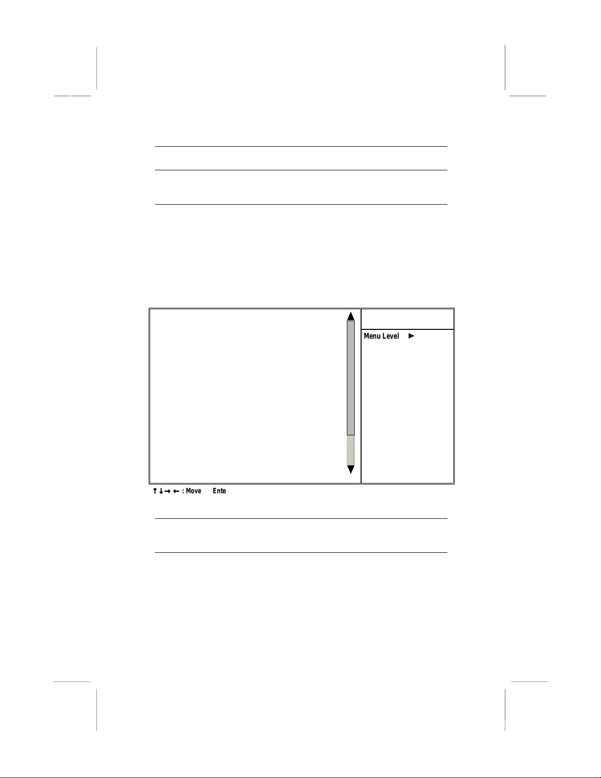
Standard CMOS Features Page
This page helps you set up basic information such as the date and
time, the IDE devices, and the diskette drives.
CMOS Setup Utility – Copyright (C) 1984 – 2001 Award Software
Date (mm:dd:yy) Mon Dec. 3 2001
Time (hh:mm:ss) 14 : 49 : 2 6
IDE Primary Master
IDE Primary Slave
IDE Secondar y Master
IDE Secondary Slave
Drive A 1.44M, 3.5 in.
Drive B None
Video EGA/VGA
Halt On All , But Keyboard
Base Memory 640K
Extended Memory 65535K
Total Memory 1024K
↑↑↑↑ ↓↓↓↓ →→→→ ←←←←
: Move Enter : Select +/-/PU/PD:Value F10: Save ESC: Exit F1:General Help
F5:Previous Values F6:BestPref. Defaults F7:Optimized Defaults
Date & Time
IDE Devices
Standard CMOS Features
Menu Level
Change the da y, month,
year and century.
Use these items to set the system date and time
Your computer has two IDE channels (Primary and
Secondary) and each channel can be installed with
one or two devices (Master and Slave). Use these
items to configure each device on the IDE channel.
Enter
Press
Esc
to close the IDE device sub-menu and return to
to display the IDE sub-menu. Press
the Standard CMOS Features page.
Floppy Drive A
Floppy Drive B
Video
Use these items to set the size and capacity of the
floppy diskette drive(s) installed in the system.
This item defines the video mode of the system.
This mainboard has a built-in VGA graphics system;
you must leave this item at the default value.
Item Help
15
Page 30

Mainboard User’s Manual
Halt On
This item defines the operation of the system POST
(Power On Self Test) routine. You can use this item
to select which types of errors in the POST are
sufficient to halt the system.
Base/Extended/
Total Memory
These items are automatically detected by the
system at start up time. These are display-only
fields. You can’t make changes to these fields.
Advanced BIOS Features Page
This page sets up more advanced information about your system.
Take care of this page with caution. Any changes can affect the
operation of your computer.
CMOS Setup Utility – Copyright (C) 1984 – 2001 Award Software
Virus Warning Disabled
Quick Power On Self Test Enabled
First Boot Device Floppy
Second Boot Device HDD-0
Third Boot Device CDROM
Boot Other Device Enabled
Swap Floppy Drive Disabled
Boot Up Floppy Seek Disabled
Boot Up NumLock Statu s On
Gate A20 Option Normal
Typematic Rate Setting Disabled
x Typematic Rate (Chars/Sec) 6
x Typematic Delay (Msec) 250
Security Option Setup
OS Select For DR AM > 64MB Non-OS2
Video BIOS Shadow Enabled
C8000-CBFF F Shadow Disabled
CC000-CFFF F Shadow Dis abled
D0000-D3FF F Shadow Disabled
↑↑↑↑ ↓↓↓↓ →→→→ ←←←←
: Move Enter : Select +/-/PU/PD:Value F10: Save ESC: Exit F1:General Help
F5:Previous Values F6:BestPref. Defaults F7:Optimized Defaults
Advanced BIO S Features
Item Help
Menu Level
Allows you to choose
the VIRUS warni ng
feature for IDE Hard
Disk boot sector
protection. If this
function is enabled
and someone attempts
to write data into this
area, BIOS will show a
warning message on
screen and alarm beep
Virus Warning
16
This mainboard has built-in virus protection in the
firmware. Use this item to enable or disable the
built-in virus protection.
Page 31

3: BIOS Setup Utility
Quick Power On
Self Test
1st/2nd/3rd Boot
Device
Boot Other
Device
Swap Floppy
Drive
Boot Up Floppy
Seek
Boot Up
NumLock Status
Gate A20 Option
Typematic Rate
Setting
Typematic Rate
(Chars/Sec)/
Delay (Msec)
Security Option
OS Select For
DRAM > 64 MB
You can enable this item to shorten the power on
testing (POST) and have your system start up a little
faster. You might like to enable this item after you
are confident that your system hardware is
operating smoothly.
Use these three items to select the priority and
order of the devices that your system searches for
an operating system at start-up time.
If you enable this item, the system will search all
other possible locations for an operating syste m if it
fails to find one in the devices specified under the
first, second, and third boot devices.
If you have two floppy diskette drives in your
system, this item allows you to swap the assigned
drive letters so that drive A becomes drive B, and
drive B becomes drive A.
If this item is enabled, it checks the geometry of the
floppy disk drives at start-up time. You don’t need
to enable this item unless you have an old diskette
drive with 360K capacity.
This item defines if the keyboard Num Lock key is
active when your system is started.
This item defines how the system handles legacy
software that was written for an earlier generation of
processors. Leave this item at the default value.
If this item is enabled, you can use the following two
items to set the typematic rate and the typematic
delay settings for your keyboard.
If the item Typematic Rate Setting is enabled, you
can use these items to define how many characters
per second are generated by a held-down key and
how many milliseconds must elapse before a helddown key begins generating repeat characters.
If you have installed password protection, this item
defines if the password is required at system start
up, or if it is only required when a user tries to enter
the Setup Utility.
This item is only required if you have installed more
than 64 MB of memory and you are running the
OS/2 operating system. Otherwise, leave this item
at the default Non-OS2.
17
Page 32
Mainboard User’s Manual
Video BIOS
Shadow
C8000-CBFFF to
D0000-D3FFF
Shadow
When enabled this item copies the VGA BIOS into
system DRAM.
When enabled, the ROM with the specified address
is copied into system DRAM. It will also reduce the
size of memory available to the system.
Advanced Chipset Features Page
This page sets up some parameters of the mainboard components
including the memory, and the system logic.
CMOS Setup Utility – Copyright (C) 1984 – 2001 Award Software
DRAM Timing By SPD Disabled
SDRAM Cycle L ength 3
Bank Interleave Disabled
DRAM Clock By Auto
DRAM Drive Str ength High
System BIOS Cacheable Enabled
Video RAM Cacheable Enabled
Frame Buffer Size 8M
AGP Aperture Si ze 64M
OnChip USB Enabled
OnChip USB 2 Disabled
USB Keyboard Support Disabled
OnChip Sound Auto
OnChip Modem Auto
PCI Master 0 WS Write Enabled
PCI#2 Access #1 Retry Enabled
AGP Master 1 WS Wri te Disabled
AGP Master 1 WS Read Disabled
Memory Parity/ECC Check Disabled
↑↑↑↑ ↓↓↓↓ →→→→ ←←←←
: Move Enter : Select +/-/PU/PD:Value F10: Save ESC: Exit F1:General Help
F5:Previous Values F6:BestPref. Defaults F7:Optimized Defaults
Advanced Chi pset Features
Item Help
Menu Level
DRAM Timing By
SPD
18
This item allows you to enable or disable the
DRAM timing defined by the Serial Presence
Detect electrical.
Page 33

3: BIOS Setup Utility
SDRAM Cycle
Length
Bank Interleave
DRAM Clock
DRAM Drive
Strength
System BIOS
Cacheable
Video RAM
Cacheable
Frame Buffer Size
AGP Aperture Size
OnChip USB
OnChip USB 2
USB Keyboard
Support
OnChip Sound
OnChip Modem
PCI Master 0 WS
Write
PCI#2 Access #1
Retry
This field enables you to set the CAS latency time
in HCLKs of 2/2 or 3/3. The system board
designer should have set the values in this field,
depending on the DRAM installed. Do not change
the values in this field unless you change
specifications of the installed DRAM or the
installed CPU.
This item allows you to enable or disable the Bank
Interleave function with 2 banks or 4 banks.
Enables the user to select the DRAM Clock.
This option determines the signal str engt h from
the mainboard for the installed DRAM.
When enabled, the System BIOS will be cached
for faster execution.
When enabled, the graphics card’s local memory
will be cached for faster execution. However, if
any program writes to this memory area, a system
error may result.
This option determines the frame buffer size
shared from the main memory for use by the
onboard VGA display.
This option determines the effective siz e of the
AGP Graphic
graphic data structures are located.
This item allows you to enable the USB port, if you
have installed a USB device on the system board.
This item allows you to enable the USB 2 port, if
you have installed more USB device on the
system board.
Enables function when the USB keyboard is being
used. Disabled (default) when an AT keyboard is
used.
Disabling this function turns off the onboard audio
chip.
This should be enabled if your system has a
modem installed on the system board and you
wish to use it.
When enabled, writes to the PCI bus are executed
with zero wait states.
When enabled, the AGP Bus (PCI#1) access to
PCI Bus (PCI#2) is executed with the error retry
feature.
Aperture
, where memory-mapped
19
Page 34
Mainboard User’s Manual
AGP Master 1 WS
Write
This implements a single delay when writing to the
AGP Bus. By default, two-wait states are used by
the system, allowing for greater stability.
AGP Master 1 WS
Read
This implements a single delay when reading to
the AGP Bus. By default, two-wait states are used
by the system, allowing for greater stability.
Memory
Parity/ECC Check
Enable this item to allow BIOS to perform a parity
check to the POST memory tests. Select Enabled
only if the system DRAM supports parity checking.
Integrated Peripherals Page
This page sets up some parameters for peripheral devices
connected to the system.
CMOS Setup Utility – Copyright (C) 1984 – 2001 Award Software
On-Chip IDE Channel0 Enabled
On-Chip IDE Channel1 Enabled
IDE Prefetch Mode Enabled
Primary Master PIO Auto
Primary Slave PIO Auto
Secondary Master PIO Auto
Secondary Slave PIO Auto
Primary Master UDMA Auto
Primary Slave UDMA Auto
Secondary Master UDMA Auto
Secondary Slave UDMA Auto
Init Display First PCI Slot
Onboard FDD Control l er Enabled
Onboard Serial Port 1 3F8/IRQ4
Onboard IR Port Disabled
x UART 2 Mode Standard
x IR Function Duplex Half
x TX,RX inverting enable No, Yes
Onboard Parallel Port 378/IRQ7
Integrated Peripherals
Menu Level
Item Help
↑↑↑↑ ↓↓↓↓ →→→→ ←←←←
: Move Enter : Select +/-/PU/PD:Value F10: Save ESC: Exit F1:General Help
F5:Previous Values F6:BestPref. Defaults F7:Optimized Defaults
On-Chip IDE
Channel 0,1
IDE Prefetch Mode
Use these items to enable or disable the PCI IDE
channels that are integrated on the mainboard.
The onboard IDE drive interfaces support IDE
prefetching, for faster drive access. If you install a
primary and secondary add-in IDE interface, set
this field to Disabled if the interface does not
support prefetching.
20
Page 35

3: BIOS Setup Utility
Primary/
Secondary Master/
Slave PIO
Primary/
Secondary Master/
Slave UDMA
Init Display First
Onboard FDD
Controller
Onboard Serial
Port 1
Onboard IR Port
UART2 Mode
IR Function
Duplex
TX, RX inverting
enable
Onboard Parallel
Port
Each channel supports a master device and a
slave device. These four items let you assign
which kind of PIO (Programmed Input/Output) is
used by IDE devices. You can choose Auto, to let
the system auto detect which PIO mode is best, or
you can install a PIO mode from 0-4.
Each channel supports a master device and a
slave device. This motherboard supports
UltraDMA and provides faster access to IDE
devices. If you install a device that supports
UltraDMA, change the appropriate item on this list
to Auto. You may have to install the UltraDMA
driver.
Use this item to define if your graphics adapter is
installed in one of the PCI slots or select Onboard
if you have a graphics system integrated on the
mainboard.
This option enables the onboard floppy disk drive
controller.
This option is used to assign the I/O address for
the onboard serial port.
This option is used to assign the I/O address for
the onboard IR port or disabled.
This field is available if the Onboard Serial Port 2
field is set to any option but “Disabled.” UART
Mode enables you to select the infrared
communication protocol—Standard (default),
HPSIR or ASKIR. HPSIR is Hewlett Packard’s
infrared communication protocol with a maximum
baud rate up to 115.2 Kbps. ASKIR is Sharp’s
infrared communication protocol with a maximum
baud rate up to 57.6 Kbps.
This field is available when UART 2 Mode is set to
either ASKIR or HPSIR. This item determines the
infrared (IR) function of the onboard infrared chip.
Full-duplex means that you can transmit and send
information simultaneously. Half duplex is the
transmission of data in both directions, but only
one direction at a time.
Defines the voltage level for Infrared module RxD
(receive) mode and TxD (transmit) mode. This
setting has to match the requirements of the
infrared module used in the system.
This option is used to assign the I/O address for
the onboard parallel port.
21
Page 36

Mainboard User’s Manual
Power Management Setup Page
This page sets up some parameters for system power management
operation.
CMOS Setup Utility – Copyright (C) 1984 – 2001 Award Software
ACPI Function Enabled
Power Management Press Enter
ACPI Suspend Type S1(POS)
PM Control by APM Yes
Video Off Option Suspend --> Off
Video Off Method Blank Screen
MODEM Use IRQ 3
Soft-Off by PWRBTN Delay 4 Sec
State After Power Failure Off
Keyboard Power On Disabled
Wake Up Event s Press Enter
↑↑↑↑ ↓↓↓↓ →→→→ ←←←←
: Move Enter : Select +/-/PU/PD:Value F10: Save ESC: Exit F1:General Help
F5:Previous Values F6:BestPref. Defaults F7:Optimized Defaults
ACPI Function
Power Management
Power Management Setup
Use this item to enable or disable the ACPI function.
This item acts like a master switch for the power-
saving modes and hard disk timeouts. If this item is
set to Max Saving, power-saving modes occur after
a short timeout. If this item is set to Min Saving,
power-saving modes occur after a longer timeout. If
the item is set to User Define, you can insert your
own timeouts for the power-saving modes.
ACPI Suspend Type
This item defines how your system suspends. The
suspend mode of S1(POS) is equivalent to a
software power down. If you select the suspend
mode of S3(STR), it is a suspend to RAM - the
system shuts down with the exception of a refresh
current to the system memory.
Item Help
Menu Level
22
Page 37

3: BIOS Setup Utility
PM Control by APM
Video Off Option
Video Off Method
MODEM Use IRQ
Soft-Off by
PWRBTN
State After Power
Failure
Keyboard Power On
Wake Up Events
This field allows you to control the PC Monitor’s
power management features via Intel-Microsoft
Advanced Power Management software. Once you
have enabled the APM interface, some settings
made in the BIOS Setup program may be overridden
by APM.
This option defines if the video is powered down
when the system is put into suspend mode.
This item defines how the video is powered down to
save power.
If you want an incoming call on a modem to
automatically resume the system from a powersaving mode, use this item to specify the interrupt
request line (IRQ) that is used by the modem. You
might have to connect the fax/modem to the
mainboard Wake On Modem connector for this
feature to work.
Under ACPI (Advanced Configuration and Power
management Interface) you can create a software
power down. In a software power down, the system
can be resumed by Wake Up Alarms. This item lets
you install a software power down that is controlled
by the normal power button on your system. If the
item is set to Instant-Off, then the power button
causes a software power down. If the item is set to
“Delay 4 Sec.” then you have to hold the power
button down for four seconds to cause a software
power down.
Use this item to set a system power state when
power restores after sudden AC power loss.
Use this item to enable or disable the keyboard
power on function.
This item opens a submenu that enables you to set
events resuming the system from a power saving
mode. Select Wake Up Events and press
display the following items: VGA, LPT & COM, HDD
& FDD, PCI Master, PowerOn by PCI Card, Wake
Up On LAN/Ring, RTC Alarm Resume, Primary
INTR, and IRQs Activity Monitoring.
Enter
to
23
Page 38

Mainboard User’s Manual
PnP/PCI Configurations Page
This page sets up some parameters for devices installed on the PCI
bus and those devices that use the system plug and play capability.
CMOS Setup Utility – Copyright (C) 1984 – 2001 Award Software
PNP OS Install ed Yes
Reset Configuration Data Disabled
Resources Contr oll e d by Auto(ESCD)
x IRQ Resources Press Enter
x DMA Resources Press Enter
PCI/VGA Palette Snoop Disabled
↑↑↑↑ ↓↓↓↓ →→→→ ←←←←
: Move Enter : Select +/-/PU/PD:Value F10: Save ESC: Exit F1:General Help
F5:Previous Values F6:BestPref. Defaults F7:Optimized Defaults
PNP OS Installed
PnP/PCI Confi gurations
Menu Level
Select Yes if you are using
a Plug and Play capable
operating system Select
No if you need the BIOS to
configure non-boot
devices.
Setting this option to “Yes” allows the PnP OS
(instead of BIOS) to assign the system resources
such as IRQ and I/O address to the ISA PnP
device.
Reset
Configuration Data
If you enable this item and restart the system, any
PnP configuration data stored in the BIOS setup is
cleared from memory. New updated data is
created.
Item Help
24
Page 39

3: BIOS Setup Utility
Resources
Controlled By
PCI/VGA Palette
Snoop
You should leave this item at the default Auto
(ESCD). Under this setting, the system
dynamically allocates resources to plug and play
devices as they are required. If you cannot get a
legacy ISA (Industry Standard Architecture)
expansion card to work properly, you might be
able to solve the problem by changing this item to
Manual, and then opening up the
and
Memory Resources
In the
IRQ Resources
any of the IRQ assignations to Legacy ISA, then
that Interrupt Request Line is reserved for a
legacy ISA expansion card. Press
the IRQ Resources sub-menu.
This item is designed to overcome some problems
that can be caused by some non-standard VGA
cards. This board includes a built-in VGA system
that does not require palette snooping so you
must leave this item disabled.
sub-menus.
sub-menu, if you change
IRQ Resources
Esc
to close
25
Page 40

Mainboard User’s Manual
Hardware Monitor Page
This page sets up some parameters for the hardware monitoring
function of this mainboard.
CMOS Setup Utility – Copyright (C) 1984 – 2001 Award Software
Current CPU Temp.
Current System Temp.
Current CPUFAN1 speed
Current CPUFAN2 speed
Vcore
2.5V
3.3V
5V
12V
↑↑↑↑ ↓↓↓↓ →→→→ ←←←←
: Move Enter : Select +/-/PU/PD:Value F10: Save ESC: Exit F1:General Help
F5:Previous Values F6:BestPref. Defaults F7:Optimized Defaults
System
Component
Characteristics
These fields provide you with information about
the systems current operating status. You cannot
make changes to these fields. The following
Hardware Monitor
Menu Level
information is displayed:
CPU Temperature
System Temperature
CPU FAN (in RPMs)
System FAN (in RPMs)
Vcore (CPU Core voltage)
2.5V (onboard 2.5 volt)
3.3V (onboard 3.3 volt)
5V (power supply’s 5 volt)
12V (power supply’s 12 volt).
Item Help
26
Page 41

3: BIOS Setup Utility
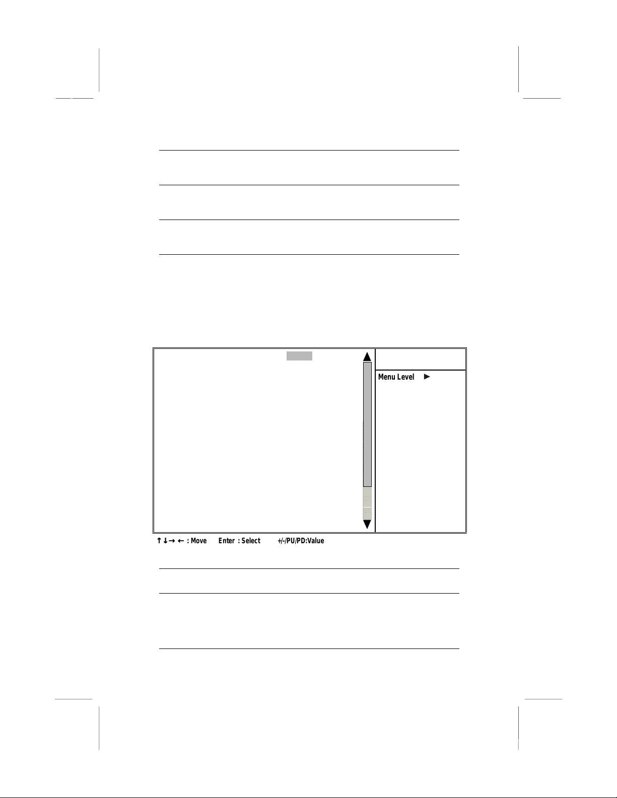
Frequency/Voltage Control
This item enables you to set the clock speed and system bus for
your system. The clock speed and system bus are determined by
the kind of processor you have installed in your system.
CMOS Setup Utility – Copyright (C) 1984 – 2001 Award Software
Auto Detect PCI Clk [Enabled]
Spread Spectrum [Disabled]
↑↑↑↑ ↓↓↓↓ →→→→ ←←←←
: Move Enter : Select +/-/PU/PD:Value F10: Save ESC: Exit F1:General Help
F5:Previous Values F6:BestPref. Defaults F7:Optimized Defaults
Auto Detect
DIMM/PCI Clk
Spread Spectrum
Frequency/Voltage Control
Menu Level
When this item is enabled, BIOS will disable the
clock signal of free DIMM and PCI slots.
If you enable spread spectrum, it can significantly
reduce the EMI(Electro-Magnetic Interference)
generated by the system.
Item Help
27
Page 42

Mainboard User’s Manual
Load BestPerf. Defaults
If you select this item and press Enter a dialog box appears. If you
press Y, and then Enter, the Setup Utility loads a set of bestperformance default values. These def aul ts are quite d em anding
and your system might not function properly if you are using
slower memory chips or other low-performance components.
Note: It is highly recommended that users enter this option to
load optimal values for accessing the best performance.
Load Optimized Defaults
If you select this item and press Enter, a dialog box appears. If you
press Y, and then Enter, the Setup Utility loads a set of fail-safe
default values. These default values are not very demanding and
they should allow your system to function with most kinds of
hardware and memory chips.
Set Password
If you highlight this item and press Enter, a dialog box appears
which lets you enter a password. You can enter no more than eight
letters or numbers. Press Enter after you have typed in the
password. A second dialog box asks you to retype the password for
confirmation. Press En ter after you have retyped it correctly. The
password is then required to access the Setup Utility or for that and
at start-up, depending on the setting of the Password Check item in
Advanced Setup.
Change or Remove the Password
Highlight this item, press Enter and type in the current password.
At the next dialog box, type in the new password, or just press
Enter to disable password protection.
28
Page 43

3: BIOS Setup Utility
Save & Exit Setup
Highlight this item and press Enter to save the changes that you
have made in the Setup Utility configuration and exit the program.
When the Save and Exit dialog box appears, press Y to save and
exit, or press N to exit without saving.
Exit Without Saving
Highlight this item and press Enter to discard any changes that
you have made in the Setup Utility and exit the setup program.
When the Exit Without Saving dialog box appears, press Y to
discard changes and exit, or press N to return to the setup main
menu.
29
Page 44

Mainboard User’s Manual
30
Page 45

4: Software & Applications
CChhaapptteerr 4
Using the Mainboard Software
About the Software CD-ROM
The support software CD-ROM that is included in the mainboard
package contains all the drivers and utility programs needed to
properly run the bundled products. Below you can find a brief
description of each software program, and the location for your
mainboard version. More information on some programs is
available in a README file, locate d in the same directo ry as the
software.
Note:
Never try to install software from a folder that is not specified for use
with your mainboard.
Before installing any software, always inspect the folder for files named
README.TXT, INSTALL.TXT, or something similar. These files may
contain important information that is not included in this manual.
4
Page 46

Mainboard User’s Manual
Drivers Installation
Audio Drivers and Software
Most of the sub-folders in this folder are empty, with a short
README file giving directions to alternate folders for the
appropriate software.
Installation for Windows XP/2000/98/98SE/ME/95
To install the audio drivers, go the directory \VIA\ AC97audio\
then run SETUP.EXE.
Installation for Windows NT4.0
1. Click Start.
2. Click Settings and then click Control Panel.
3. Double-click the Multimedia icon.
4. Select the Devices tab.
5. Click Add.
6. Select the item "Unlisted or Updated Driver" in the
List of Drivers in the list box and then specify the path
to the PCI audio NT drivers (\VIA\ AC97audio\
Winnt40).
7. Select “Avance Logic, Inc. AC‘97¨ and click OK.
8. Choose the proper I/O or click OK for the default
setting. Setup installs the drivers and software.
9. Restart the Windows NT system when prompted.
VIA Service Pack
This folder has software and drivers for the IDE that is integrated on this
mainboard. Drivers are provided for Windows XP/2000/98/98SE/ME/95
and Windows NT.
Installation for Windows XP/2000/98/98SE/ME/95/NT
To install the IDE drivers, go to the directory \VIA\Ide\; then run
SETUP.EXE to install the IDE driver for your operating system.
32
Page 47

4: Software & Applications
Utility Software Reference
All the utility software available from this page is Windows
compliant. They are provided only for the convenience of the users.
The following software is furnished under license and may only be
used or copied in accordance with the terms of the license.
Note:
This software is subject to change at anytime without prior notice.
Please refer to the support CD for available software.
Award Flash Memory Utility
This utility lets you erase the system BIOS stored on a Flash
Memory chip on the mainboard, and lets you copy an updated
version of the BIOS to the chip. Proceed with caution when using
this program. If you erase the current BIOS and fail to write a new
BIOS, or write a new BIOS that is incorrect, your system will
malfunction. Refer to Chapter 3, Using BIOS for more information.
PC-CILLIN
The PC-CILLIN software program provides anti-virus protection
for your system. This program is available for Windows
2000/ME/98SE and Windows NT. Be sure to check the readme.txt
and install the appropriate anti-virus software for your operating
system.
We strongly recommend users to install this free anti-virus
software to help protect your system against viruses.
MediaRing Talk – Telephony Software
To install the MediaRing Talk voice modem software for the built-in modem,
go to the directory \UTILITY\MEDIARING TALK, then run MRTALKSETUP72.EXE to install the application software.
Super Voice – Fax/Modem Software
To install the Super Voice voice, fax, dat a communication
application for use with the built-in fax/modem, go the directory
\UTILITY\SUPER_VOICE, then run PICSHELL.EXE to install
the application software.
33
Page 48

Mainboard User’s Manual
CD Ghost
The CD Ghost software enables you to create a virtual cabinet of
CD-ROM drives on your system to help you categorize and
organize your CD collection. A user-friendly interface assists you
in quickly creating images of both CDs and DVDs onto your
system. To install the software, run SETUP.EXE from the
following directory:
\UTILITY\CDGHOST\ENG\CDGHOST
Recovery Genius
The Recovery Genius software program is an innovative windows
application system that protects your Hard Disk Drive from virus
intrusion, accidental deletions and from system corruption. To
install the Recovery Genius software program run SETUP.EXE
from the following directory:
\UTILITY\RECOVERY GENIUS\ENG\RECOVERYGENIUS
Language Genius
The Language Genius is a software –based product that helps you to
learn new languages. To install the Language Genius software program
run SETUP.EXE from the following directory:
\UTILITY\LANGUAGE GENIUS\ENG\LANGUAGEGENIUS
PageABC
The PageABC application software enables you to create your very own
home page. To install the PageABC, go to the directory \UTILITYPageABC,
and then run SETUP.EXE to install the application software.
This concludes Chapter 4.
34
 Loading...