

Page 1

Mainboard User’s Manual
This publication, including all photographs, illustrations and
software, is protected under inte rna tional copyright laws, with all
rights reserved. Neither this manual, nor any of the material
contained herein, may be reproduced without the express written
consent of the manufacturer.
The information in this document is subject to change without
notice. The manufacturer makes no representations or warranties
with respect to the contents hereof and specifically disclaims any
implied warranties of merchantability or fitness for any particular
purpose. Further, the manufacturer reserves the right to revise this
publication and to make changes from time to time in the content
hereof without obligation of the manufacturer to notify any person
of such revision or changes.
Trademarks
IBM, VGA, and PS/2 are registered trademarks of International
Business Machines.
AMD and Athlon are registered trademarks of Advanced Micro
Devices Inc.
Intel, Pentium, Pentium-II, and MMX are registered trademarks of
Intel Corporation.
Microsoft, MS-DOS and Windows 95/98/NT are registered
trademarks of Microsoft Corporation.
Sound Blaster is a trademark of Creative Technology Ltd.
PC-cillin and ChipAwayVirus are trademarks of Trend Micro Inc.
Award is a trademark of Award Software Inc.
A3D is a registered trademark of Aureal Inc.
MediaRing Talk is a registered trademark of MediaRing Inc.
Other names used in this publication may be trademarks and are
acknowledged.
Copyright © 2000
All Rights Reserved
MS7167D, V1.5
V133X/August 2000
Page 2

MS7167 Mainboard User’s Manual
Table of Contents
Chapter 1: Introduction................................................................... 1
Key Features...........................................................................2
Package Contents.................................................................... 4
Static Electricity Precautions..................................................4
Pre-Installation Inspection ...................................................... 4
Chapter 2: Mainboard Installation .................................................. 5
Mainboard Components.......................................................... 6
I/O Ports.................................................................................. 6
Install A CPU.......................................................................... 7
Install Memory........................................................................ 8
Setting Jumper Switches......................................................... 9
Install the Mainboard............................................................ 10
Install Other Devices.............................................................11
Expansion Slots..................................................................... 13
Chapter 3: BIOS Setup Utility......................................................15
Introduction........................................................................... 15
Running the Setup Utility.....................................................16
Standard CMOS Features Page............................................. 17
Advanced BIOS Features Page............................................. 18
Advanced Chipset Features Page.......................................... 21
Integrated Peripherals Page...................................................24
Power Management Setup Page............................................27
PnP/PCI Configurations Page............................................... 29
Hardware Monitor Page........................................................ 31
Frequency/Voltage Control Page.......................................... 32
Load Best Performance Defaults..........................................33
Load Optimized Defaults...................................................... 33
Set Password......................................................................... 33
Save & Exit Setup................................................................. 33
Exit Without Saving.............................................................. 34
Chapter 4: Software & Applications............................................. 35
About the Software............................................................... 35
Folders for this Mainboard....................................................35
Running the Support CD-ROM............................................ 36
Utility Folder Installation Notes ........................................... 36
Award Flash Memory Utility
Mainboard (MS7167D) Installation Notes ........................... 37
.......................................... 36
II
Page 3

MS7167 Mainboard User’s Manual
Appendix A: Gamut2000 .......................................................... A1
1. GAMUT2000 Family ...................................................... A2
1.1 LifeAmp - Versatile Audio Playback System ........... A2
1.2 AudioPort - Audio Transportation System ............... A4
2. Installation ...................................................................... A5
2.1 Before Beginning: System Requirements ................. A5
2.2 Uninstalling the Previous of GAMUT2000............... A5
3. Main Console .................................................................. A7
3.1 Introduction ............................................................... A7
3.2 Function and Operation ............................................. A7
3.3 Main Menu ................................................................ A9
III
Page 4

Page 5

1: Introduction
Chapter 1
Introduction
This mainboard has a Socket-370 processor socket for an Intel
PPGA/FCPGA Celeron or FCPGA Pentium III processor. You
can install any one of these processors on the mainboard. The
mainboard supports front-side bus speeds of 66MHz, 100MHz or
133MHz.
This mainboard uses the VIA PM133 chipset which provides CPU
Plug & Play through firmware, a 4X AGP slot for highly graphics
display, CPU Plug & Play through firmware, and integrates a
Savage4 2D/3D/Video Accelerator. The mainboard has a built-in
AC97 Codec, provides an AMR (Audio Modem Riser) slot to
support Audio and Modem application. In addition, the mainboard
has an extended set of ATX I/O Ports including PS/2 keyboard
and mouse ports, two USB ports, a parallel port, a VGA port, a
serial port, a game port and audio ports.
This mainboard has all the features you need to develop a powerful
multimedia workstation. The board is ATX size and has power
connectors for an ATX power supply.
1
Page 6

MS7167 Mainboard User’s Manual
Key Features
The key features of this mainboard include:
Socket-370 Processor Support
♦ Supports PPGA/FCPGA Celeron CPUs which provide
Pentium II performance with integrated L1 and L2 cache
♦ Supports FCPGA Pentium III CPUs
♦ Supports 66MHz, 100MHz or 133MHz Front-Side Bus
All processors are automatically configured using firmware and a
synchronous Host/DRAM Clock Scheme.
Memory Support
♦ Three DIMM slots for 168-pin SDRAM memory modules
♦ Support for 100/133 MHz memory bus
♦ Maximum installed memory is 3 x 512MB = 1.5GB
Expansion Slots
♦ One AMR slot for a special audio/modem riser card
♦ One AGP4X slot for AGP 2.0-compliant interface.
♦ Four 32-bit PCI slots for PCI 2.2-compliant bus interface.
♦ One 8/16-bit ISA slot.
Onboard IDE channels
♦ Primary and Secondary PCI IDE channels
♦ Support for PIO (programmable input/output) modes
♦ Support for Multiword DMA modes
♦ Support for Bus Mastering and Ultra DMA 33/66 modes
Power Supply and Power Management
♦ ATX power supply connector
♦ Supports ACPI, previous PMU and suspend switch
♦ Supports Wake on LAN and Wake on Alarm
2
Page 7

1: Introduction
AC97 Codec
♦ Compliant PC97 2.1 specification
♦ Supports 18-bit ADC (Analog Digital Converter) and DAC
(Digital Analog Converter) as well as 18-bit stereo fullduplex codec
Onboard I/O Ports
♦ Provides PC99 Color Connectors for easy peripheral device
connections
♦ Floppy disk drive connector with 1Mb/s transfer rate
♦ Two serial ports with 16550-compatible fast UART
♦ One parallel port with ECP and EPP support
♦ Two USB ports, optional two USB ports module
♦ Two PS/2 ports for keyboard and mouse
♦ One infrared port connector for optional module
Hardware Monitoring
♦ Built-in hardware monitoring for CPU & System
temperatures, fan speeds and mainboard voltages
Onboard Flash ROM
♦ Automatic CPU and board configuration
♦ Supports Plug and Play configuration of peripheral devices
and expansion cards
♦ Built-in virus protection using Trend’s ChipAwayVirus
provides boot process virus protectio n.
Bundled Software
♦ PC-Cillin provides automatic virus protection under
Windows 95/98
♦ MediaRing Talk provides PC to PC or PC to Phone
internet phone communication
♦ Corel WordPerfect Suite 8 is a Microsoft Windows
office application suite (optional)
Dimensions
♦ Micro ATX form factor (30.5cm x 19cm)
®
3
Page 8

MS7167 Mainboard User’s Manual
Package Contents
Your mainboard package ships with the following items:
!
The mainboard
!
This User’s Guide
!
1 UDMA/66 IDE cable
!
1 Floppy disk drive cable
!
Support software on CD-ROM disk
Static Electricity Precautions
Components on this mainboard can be damaged by static
electricity. Take the following precautions when unpacking the
mainboard and installing it in a system.
1. Keep the mainboard and other components in their original
static-proof packaging until you are ready to install them.
2. During installation, wear a grounded wrist strap if possible. If
you don’t have a wrist strap, discharge static electricity by
touching the bare metal of the system chassis.
3. Handle the mainboard carefully by the edges. Avoid touching
the components unless it is absolutely necessary. During
installation put the mainboard on top of the static-protection
packaging it came in with the component side facing up.
Pre-Installation Inspection
1. Inspect the mainboard for damage to the components and
connectors on the board.
2. If you suspect that the mainboard has been damaged, do not
connect power to the system. Contact your mainboard vendor
and report the damage.
4
Page 9

2: Mainboard Installation
Chapter 2
Mainboard Installation
To install this mainboard in a system, follow the procedures in this
chapter:
!
Identify the mainboard components
!
Install a CPU
!
Install one or more system memory modules
!
Verify that any jumpers or switches are set correctly
!
Install the mainboard in a system chassis (case)
!
Connect any extension brackets or cables to the mainboard
connector headers
!
Install any other devices and make the appropriate connections
to the mainboard connector headers.
Note:
1. Before installing this mainboard, make sure jumper J8 is set to
Normal setting. See this chapter for information on locating J8
and the setting options.
2. Never connect power to the system during installation. Doing
so may damage the mainboard.
5
Page 10
MS7167 Mainboard User’s Manual
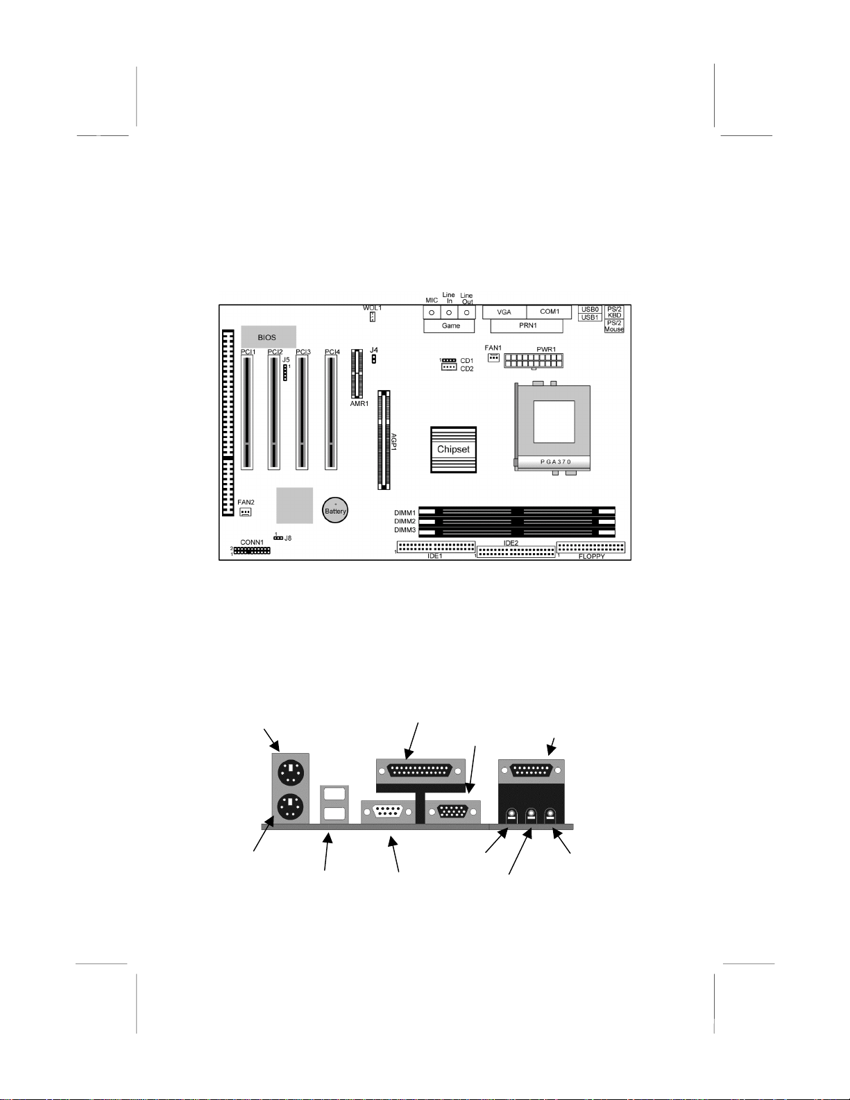
Mainboard Components
Use the diagram below to identify the major components on the
mainboard.
Note: Any jumpers on your mainboard that do not appear in
this illustration are for testing only.
I/O Ports
The illustration below shows a side view of the built-in I/O ports
on the mainboard.
PS/2 Mouse
PS/2 Keyboard
USB Ports
6
Parallel Port
Line-Out Jack
Serial Port COM1/3
VGA Port
Line-In Jack
Game/MIDI Port
Microphon e Jac k
Page 11
2: Mainboard Installation
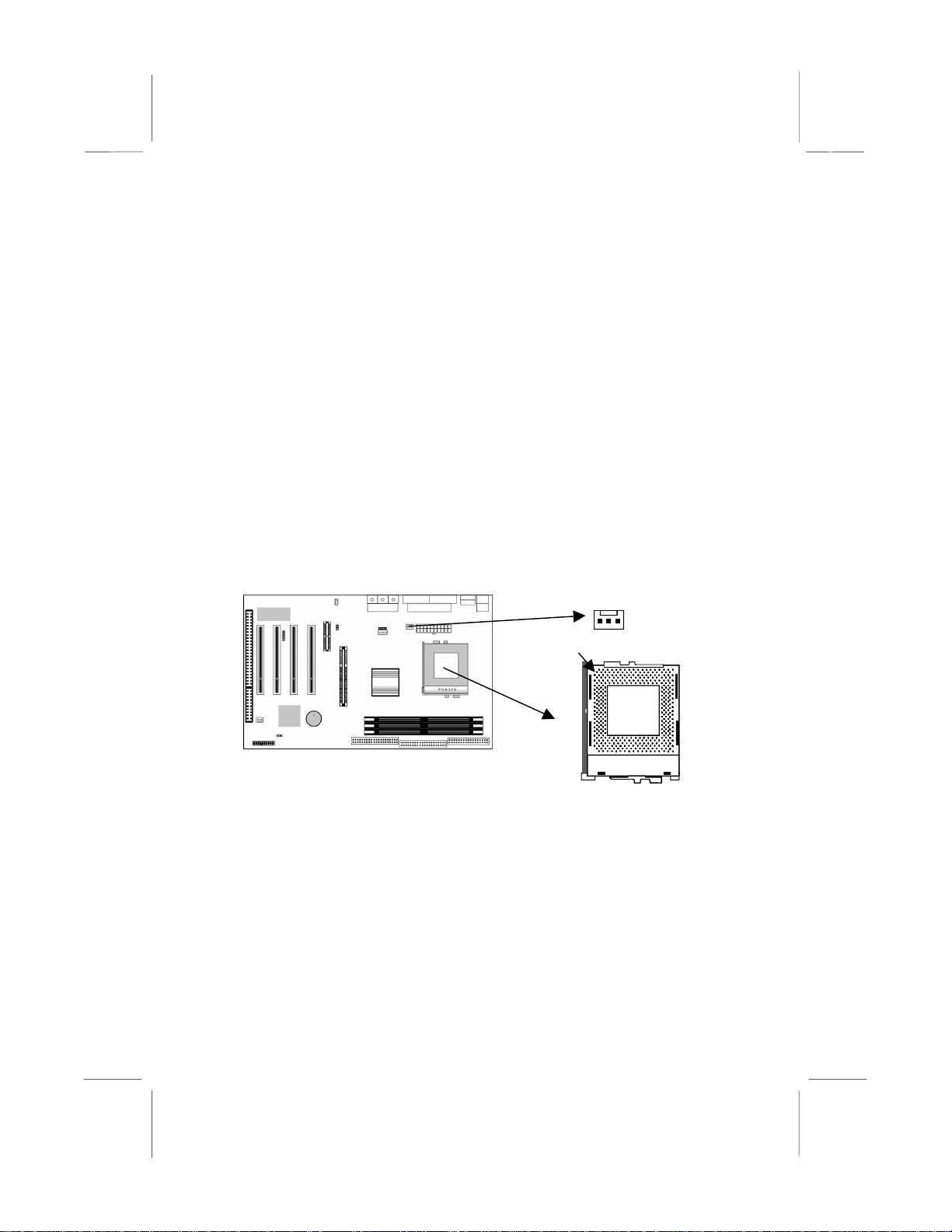
Install A CPU
This mainboard has a Socket-370 which supports PPGA/FCPGA
Celeron and FCPGA Pentium III processors.
Do not try to install a Socket 7 processor in the Socket-370. A
Socket 7 processor such as the Pentium-MMX, or the AMD K5/K6
does not fit in the Socket 370.
The following list notes the processors that are currently supported
by this mainboard.
FCPGA Pentium III: 500~933MHz, FSB: 100MHz, 133MHz
PPGA/FCPGA Celeron: 300~600MHz, FSB: 66 MHz
Installing a Socket-370 Processor
A processor installs into the ZIF (Zero Insertion Force) Socket-370
on the mainboard.
1. Locate the Socket-370 and FAN1. Pull the locking lever out
slightly from the socket and raise it to the upright position.
FAN1
Pin-1 Corner
Socket-370
2. On the processor, identify the Pin-1 corner by its beveled edge.
3. On the Socket-370, identify the Pin-1 corner. The Pin-1 corner
is at the top of the locking lever when it is locked.
4. Match the Pin-1 corners and insert the processor into the
socket. No force is required and the processor should drop into
place freely.
5. Swing the locking lever down and hook it under the catch on
the side of the socket. This secures the CPU in the socket.
6. All processors should be installed with a combination
heatsink/cooling fan, connect the cable from the fan to the
CPU fan power connector FAN1.
7
Page 12

MS7167 Mainboard User’s Manual
Install Memory
The mainboard has three DIMM sockets for system memory
modules. You must install at least one memory module in order to
use the mainboard.
DIMM1
DIMM2
DIMM3
For this mainboard, you must use 168-pin, 3.3V unbuffered PC100
or PC133 SDRAM memory modules. You can install any size
memory module from 32 MB to 512MB, so the maximum memory
size is 3 x 512MB = 1.5GB.
The edge connectors on the memory modules have cut outs, which
coincide with spacers in the DIMM sockets so that memory
modules can only be installed in the correct orientation.
To install a module, push the retaining latches at either end of the
socket outwards. Position the memory module correctly and insert
it into the DIMM socket. Press the module down into the socket so
that the retaining latches rotate up and secure the module in place
by fitting into notches on the edge of the module.
8
Page 13
2: Mainboard Installation
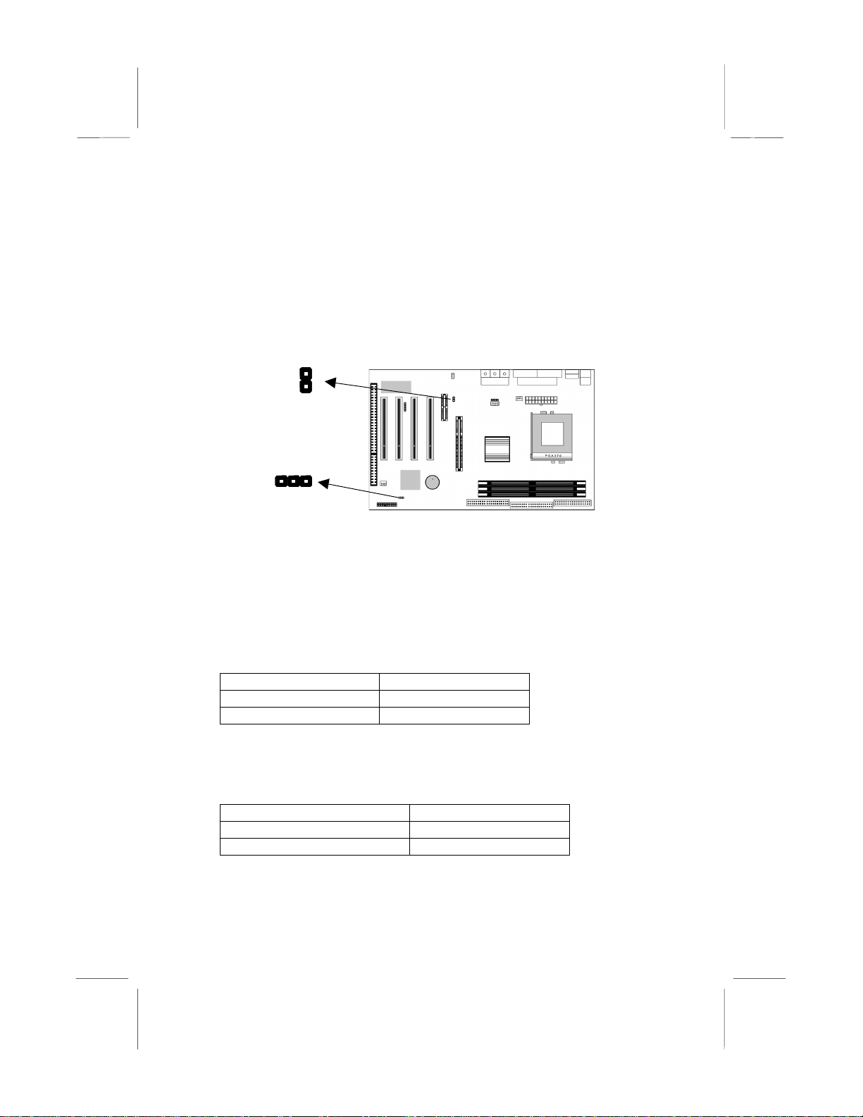
Setting Jumper Switches
Jumpers are sets of pins which can be connected together with
jumper caps. The jumper caps change the way the mainboard
operates by changing the electronic circuits on the mainboard. If a
jumper cap connects two pins, we say the pins are SHORT. If a
jumper cap is removed from two pins, the pins are OPEN.
J4
J8
1
Jumper J8: Clear CMOS Memory
Use this jumper to clear the contents of the CMOS memory. You
may need to clear the CMOS memory if the settings in the Setup
Utility are incorrect and prevent your mainboard from operating.
To clear the CMOS memory, disconnect all the power cables from
the mainboard and then move the jumper cap into the CLEAR
setting for a few seconds.
Function Jumper Setting
Normal Operation Short Pins 1-2
Clear CMOS Memory Short Pins 2-3
Jumper J4: Codec Selector
Use this jumper to select the onboard audio codec or Audio
Modem Riser (AMR) slot.
Function Jumper Setting
Primary codec onboard Short Pins 1-2
Primary codec on AMR slot Open Pins 1-2
9
Page 14

MS7167 Mainboard User’s Manual
4
h
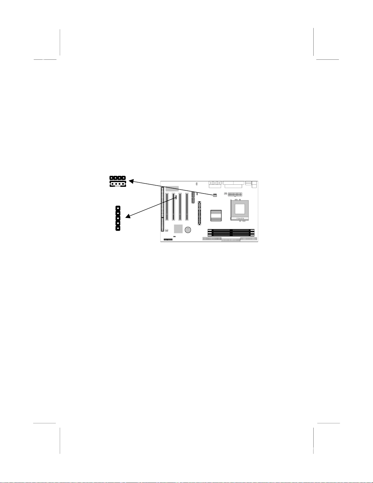
Install the Mainboard
Install the mainboard in a system chassis (case). The board is an
ATX size mainboard with a twin-tier of I/O ports. Ensure that your
case has an I/O cover plate that matches the ports on this
mainboard.
Install the mainboard in a case. Follow the instructions provided by
the case manufacturer using the hardware and internal mounting
points on the chassis.
PWR1
FAN2
CONN1
Connect the power connector from the power supply to the PWR1
connector on the mainboard.
If there is a cooling fan installed in the system chassis, connect the
cable from the cooling fan to the FAN2 fan power connector on the
mainboard.
Connect the case switches and indicator LEDs to the CONN1
switch and LED connector header. See the illustration below for a
guide to the header pin assignments.
Turbo LED
Pins 13-1
Power LED
Pins 2-4-6
2
1
Speaker
Pins 1-3-5-7
Suspend Switc
Pins 11-12
Reset Switch
Pins 17-18
Power Button
Pins 21-22
22
21
HDD LED
Pins 15-16
10
Page 15
2: Mainboard Installation
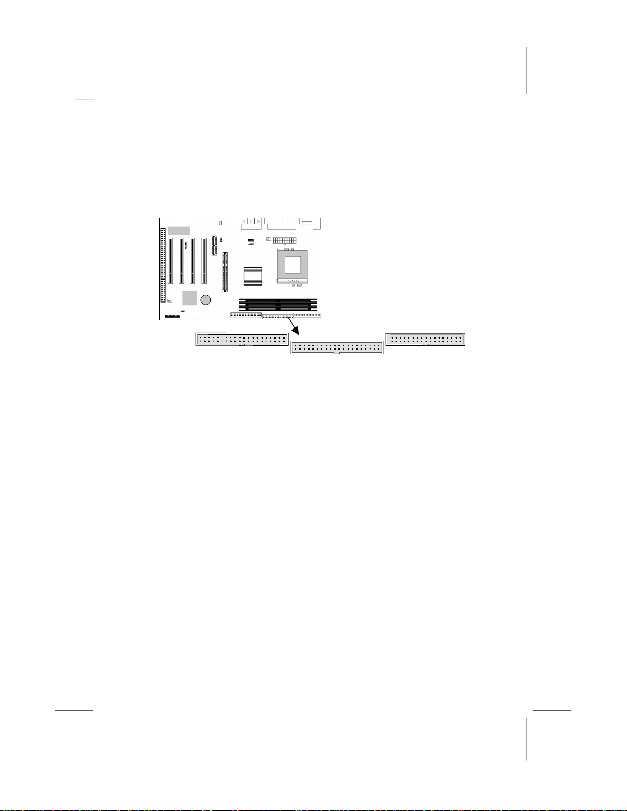
Install Other Devices
Install and connect any other devices in the system following the
steps below.
1 1 1
IDE1
IDE2
FLOPPY
Floppy Disk Drive
The mainboard ships with a floppy disk drive cable that can
support one or two drives. Drives can be 3.5” or 5.25” wide, with
capacities of 360K, 720K, 1.2MB, 1.44MB, or 2.88MB.
Install your drives and connect power from the system power
supply. Use the cable provided to connect the drives to the floppy
disk drive header FLOPPY.
IDE Devices
IDE devices include hard disk drives, high-density diskette drives,
and CD-ROM or DVD-ROM drives, among others.
The mainboard ships with an IDE cable that can support one or two
IDE devices. If you connect two devices to a single cable, you
must configure one of the drives as Master and one of the drives as
Slave. The documentation of the IDE device will tell you how to
configure the device as a Master or Slave device. The Master
device connects to the end of the cable.
Install the device(s) and connect power from the system power
supply. Use the cable provided to connect the device(s) to the
Primary IDE channel connector IDE1 on the mainboard.
If you want to install more IDE devices, you can purchase a second
IDE cable and connect one or two devices to the Secondary IDE
11
Page 16
MS7167 Mainboard User’s Manual
channel connector IDE2 on the mainboard. If you have two
devices on the cable, one must be Master and one must be Slave.
Internal Sound Connections
If you have installed a CD-ROM drive or DVD-ROM drive, you
can connect the drive audio cable to the onboard sound system.
On the mainboard, locate the two 4-pin connectors CD1 and CD2.
There are two kinds of connector because different brands of CDROM drive have different kinds of audio cable connectors.
Connect the cable to the appropriate connector.
CD1
CD2
J5-IR Header
1
Infrared Port
You can connect an infrared port to the mainboard. You can
purchase this option from third-party vendors.
1. Locate the infrared port IR header on the mainboard.
2. If you are adding an infrared port, connect the ribbon cable
from the port to the header and then secure the port to an
appropriate place in your system chassis.
12
Page 17

2: Mainboard Installation
Expansion Slots
This mainboard has four 32-bit PCI expansion slots, one AGP, one
AMR slot and one 8/16-bit ISA slot.
PCI1
PCI2
ISA1
AMR1
AGP1
Follow the steps below to install a PCI/AMR/AGP/ISA expansion
card.
1. Locate the AGP, AMR, PCI or ISA slots on the mainboard.
2. Remove the slot cover for this slot from the system chassis.
3. Insert the expansion card edge connector into the slot and press
it firmly down into it so that it is fully inserted.
4. Secure the expansion card bracket to the system chassis using
the screw that held the slot cover in place.
AMR Slot
The AMR (Audio Modem Riser) slot is an industry standard slot
that allows for the installation of a special audio/modem riser card.
Different territories have different regulations regarding the
specifications of a modem card. You can purchase an AMR card
that is approved in your area and install it directly into the AMR
slot.
13
Page 18
MS7167 Mainboard User’s Manual
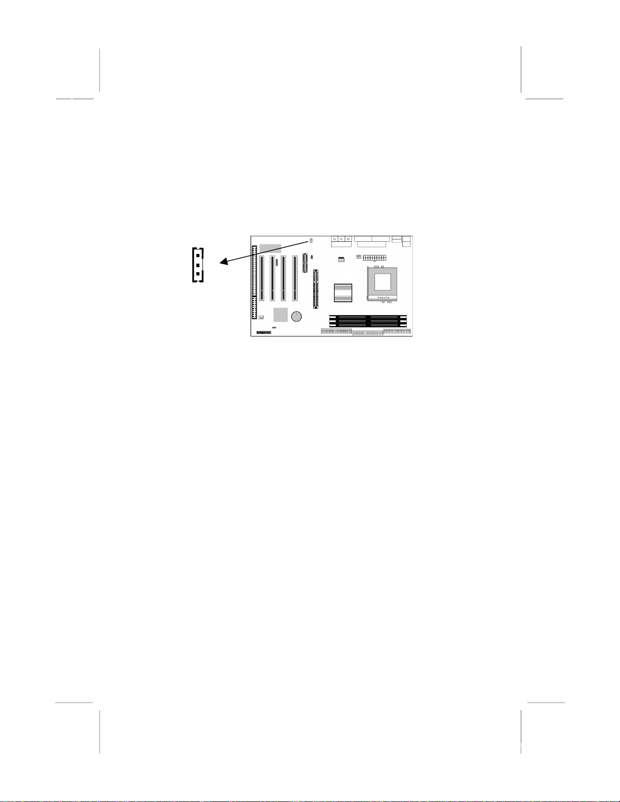
Wake On LAN (WOL)
If you have installed a LAN adapter expansion card, connect the
card to the Wake On LAN connector WOL1. This allows
incoming traffic to resume the system from a software power down.
You need to enable this feature in the system setup utility.
WOL1
Header
14
Page 19

3: BIOS Setup Utility
Chapter 3
BIOS Setup Utility
Introduction
The BIOS Setup Utility records settings and information about
your computer such as the date and time, the kind of hardware
installed, and various configuration settings. Your computer uses
this information to initialize all the components when booting up
and functions as the basis for coordination between system
components.
If the Setup Utility configuration is incorrect, it may cause the
system to malfunction. It can even stop your computer from
booting properly. If this happens, you can use the clear CMOS
jumper to clear the CMOS memory used to store the configuration
information, or you can hold down the Page Up key while you
reboot your computer. Holding down the Page Up key also clears
the setup information.
You can run the setup utility and manually make changes to the
configuration. You might need to do this to configure some of the
hardware that you install on or connect to the mainboard, such as
the CPU, system memory, disk drives, etc.
15
Page 20
MS7167 Mainboard User’s Manual
Running the Setup Utility
Each time your computer starts, before the operating system loads,
a message appears on the screen that prompts you to “Press
<DEL> to enter SETUP”. When you see this message, press the
Delete key and the Main menu page of the Setup Utility appears on
your monitor.
CMOS Setup Utility – Copyright (C) 1984 – 2000 Award Software
Standard CMOS Features
Advanced BIO S Features
Advanced Chi pset Features
Integrated Peripherals
Power Management Setup
PnP/PCI Configurations
Hardware Monitor
Esc : Quit F9: Menu in BIOS
F10 : Save & Exit Setup
Time, Date, Hard Disk Type . . .
Frequency/Voltage Contr ol
Load Best Perform an ce Def aul ts
Load Optimized Defa ul ts
Set Password
Save & Exit Setup
Exit Without Saving
↑↑↑↑ ↓↓↓↓ →→→→
←←←←
: Select Item
Listed below are explanations of the keys displayed at the bottom
of the screens:
Key Function
Esc Escape key: Exits the current menu
←←←← ↓↓↓↓ ↑↑↑↑ →→→→
+/−/PU/P
D
Cursor keys: Scroll through the items on a menu
Plus, minus, Page Up and Page Down keys:
Modify the selected field’s values
F10 F10 key: Saves the current configuration and exits
setup
F1 F1 key: Displays a screen that explains all key
functions
F5 F5 key: Loads previously saved values to CMOS
F6 F6 key: Loads a best performance configuration
for the normal system.
F7 F7 key: Loads an optimum set of values for peak
performance
16
Page 21
3: BIOS Setup Utility
Standard CMOS Features Page
Use this page to set basic information such as the date and time, the
IDE devices, and the diskette drives.
CMOS Setup Utility – Copyright (C) 1984 – 2000 Award Software
Date (mm:dd:yy) Tue, Sep 5 2000
Time (hh:mm:ss) 12 : 8 : 59
IDE Primary Master Press Enter 4303 MB
IDE Primary Slave Press Enter None
IDE Secondary Master Press Enter None
IDE Secondary Slave Press Enter None
Drive A 1.44M, 3.5 in.
Drive B None
Video EGA/VGA
Halt On All Errors
↑↑↑↑ ↓↓↓↓ →→→→ ←←←←
: Move Enter : Select +/-/PU/PD:Value:F10: Save ESC: Exit
F1:General Help F5:Previous Values F6:Fail-Safe
Defaults F7:Optimized Defaults
Date & Time
IDE Devices
Standard CMOS Features
Menu Level
Change the da y, month,
year and century.
Use these items to set the system date and time
Your computer has two IDE channels (Primary and
Secondary) and each channel can be installed with
one or two devices (Master and Slave). Use these
items to configure each device on the IDE channel.
Enter
Press
Esc
to close the IDE device sub-menu and return to
to display the IDE sub-menu. Press
the Standard CMOS Features page.
Floppy Drive A
Floppy Drive B
Video
Use these items to set the size and capacity of the
floppy diskette drive(s) installed in the system.
This item defines the video mode of the system.
This mainboard has a built-in VGA graphics system;
you must leave this item at the default value.
Halt On
This item defines the operation of the system POST
(Power On Self Test) routine. You can use this item
to select which types of errors in the POST are
sufficient to halt the system.
Item Help
17
Page 22
MS7167 Mainboard User’s Manual
Advanced BIOS Features Page
Use this page to set more advanced information about your system.
Take some care with this page. Making changes can affect the
operation of your computer.
CMOS Setup Utility – Copyright (C) 1984 – 2000 Award Software
Trend ChipAway Virus Enabled
CPU Internal C ache Enabled
External Cache Enabled
CPU L2 Cache ECC Checking Enabled
Processor N umber Feature Enabled
Quick Power On Self Test Enabled
First Boot Device HDD-0
Second Boot Device Floppy
Third Boot Device CDROM
Boot Other Device Enabled
Swap Floppy Drive Disabled
Boot Up Floppy Seek Disabled
Boot Up NumLock Statu s On
Gate A20 Option Fast
Typematic Rate Setting Disabled
x Typematic Rate (Chars/Sec) 6
x Typematic Delay (Msec) 250
Security Option Setup
OS Select For DR AM > 64MB Non-OS2
↑↑↑↑ ↓↓↓↓ →→→→ ←←←←
: Move Enter : Select +/-/PU/PD:Value:F10: Save ESC: Exit
F1:General Help F5:Previous Values F6:Fail-Safe
Defaults F7:Optimized Defaults
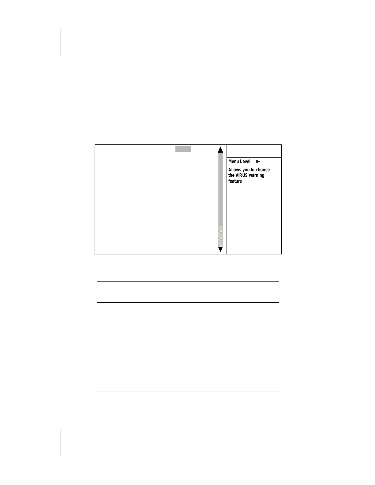
Trend ChipAway
Virus
Advanced BIO S Features
Menu Level
Allows you to choose
the VIRUS warni ng
feature for IDE Hard
Disk boot sector
protection. If this
function is enabled
and someone attempts
to write data into this
area, BIOS will show a
warning message on
screen and alarm beep
This mainboard has built-in virus protection in the
firmware. Use this item to enable or disable the
built-in virus protection.
CPU Internal
Cache
All the processors that can be installed in this
mainboard use internal (level 1) cache memory to
improve performance. Leave this item at the default
External Cache
value
Enabled
Most processors that can be installed in this system
for better performance.
use external (L2) cache memory to improve
performance. The exceptions are older SEPP
Celeron CPUs running at 266 or 300 MHz. Enable
this item for all but these two processors.
CPU L2 Cache
ECC Checking
This item enables or disables ECC (Error Correction
Code) error checking on the CPU cache memory.
We recommend that you leave this item at the
default value.
Item Help
18
Page 23

3: BIOS Setup Utility
Processor
Number Feature
Quick Power On
Self Test
1st/2nd/3rd Boot
Device
Boot Other
Device
Swap Floppy
Drive
Boot Up Floppy
Seek
Boot Up
NumLock Status
Gate A20 Option
Typematic Rate
Setting
Typematic Rate
(Chars/Sec)/
Delay (Msec)
Security Option
OS Select For
DRAM > 64 MB
Video BIOS
When enabled, the CPU will show its processor
number (ID code).
You can enable this item to shorten the power on
testing (POST) and have your system start up a little
faster. You might like to enable this item after you
are confident that your system hardware is
operating smoothly.
Use these three items to select the priority and
order of the devices that your system searches for
an operating system at start-up time.
If you enable this item, the system will search all
other possible locations for an operating syste m if it
fails to find one in the devices specified under the
first, second, and third boot devices.
If you have two floppy diskette drives in your
system, this item allows you to swap the assigned
drive letters so that drive A becomes drive B, and
drive B becomes drive A.
If this item is enabled, it checks the geometry of the
floppy disk drives at start-up time. You don’t need
to enable this item unless you have an old diskette
drive with 360K capacity.
This item defines if the keyboard Num Lock key is
active when your system is started.
This item defines how the system handles legacy
software that was written for an earlier generation of
processors. Leave this item at the default value.
If this item is enabled, you can use the following two
items to set the typematic rate and the typematic
delay settings for your keyboard.
If the item Typematic Rate Setting is enabled, you
can use these items to define how many characters
per second are generated by a held-down key and
how many milliseconds must elapse before a helddown key begins generating repeat characters.
If you have installed password protection, this item
defines if the password is required at system start
up, or if it is only required when a user tries to enter
the Setup Utility.
This item is only required if you have installed more
than 64 MB of memory and you are running the
OS/2 operating system. Otherwise, leave this item
at the default Non-OS2.
When enabled this item copies the VGA BIOS into
19
Page 24

MS7167 Mainboard User’s Manual
Shadow
C8000-CBFFF to
DC000-DFFFF
Shadow
system DRAM.
When enabled, the ROM with the specified address
is copied into system DRAM. It will also reduce the
size of memory available to the system.
20
Page 25
3: BIOS Setup Utility
Advanced Chipset Features Page
This page sets some of the parameters of the mainboard
components including the memory, and the system logic.
CMOS Setup Utility – Copyright (C) 1984 – 2000 Award Software
Bank 0/1 DRAM Timing SDRAM 8/10ns
Bank 2/3 DRAM Timing SDRAM 8/10ns
Bank 4/5 DRAM Timing SDRAM 8/10ns
SDRAM Cycle L ength 3
DRAM Clock Host CLK
P2C/C2P Conc urrency Enabled
Fast R-W Turn Around Disabled
System BIOS Cacheable Enabled
Video RAM Cacheable Enabled
Frame Buffer Size 8M
AGP Aperture Si ze 64M
AGP 4X Mode Enabled
AGP Driving Control Auto
X AGP Driving Value DA
OnChip USB Enabled
USB Keyboard Support Disabled
OnChip Sound Auto
OnChip Modem Auto
CPU to PCI Write Buffer Enabled
↑↑↑↑ ↓↓↓↓ →→→→ ←←←←
: Move Enter : Select +/-/PU/PD:Value:F10: Save ESC: Exit
F1:General Help F5:Previous Values F6:Fail-Safe
Defaults F7:Optimized Defaults
Bank 0/1 2/3 4/5
DRAM Timing
Advanced Chi pset Features
Menu Level
This item allows you to select the timing for the
DRAM slots, depending on whether the board has
paged SDRAMs.
SDRAM Cycle
Length
This field enables you to set the CAS latency time
in HCLKs of 2/2 or 3/3. The system board
designer should have set the values in this field,
depending on the DRAM installed. Do not change
the values in this field unless you change
specifications of the installed DRAM or the
installed CPU.
DRAM Clock
P2C/C2P
Concurrency
Enables the user to select the DRAM Clock.
When disabled, the CPU bus is occupied during
the entire PCI operation period.
Item Help
21
Page 26

MS7167 Mainboard User’s Manual
Fast R-W Turn
Around
System BIOS
Cacheable
Video RAM
Cacheable
Frame Buffer Size
AGP Aperture Size
AGP 4X Mode
AGP Driving
Control
AGP Driving Value
OnChip USB
USB Keyboard
Support
OnChip Sound
OnChip Modem
CPU to PCI Write
Buffer
When this is enabled, the chipset will insert one
extra clock to the turn-around of back-to-back
DRAM cycles.
When enabled, the System BIOS will be cached
for faster execution.
When enabled, the graphics card’s local me mory
will be cached for faster execution. However, if
any program writes to this memory area, a system
error may result.
This option determines the frame buffer size
shared from the main memory for use by the
onboard VGA display.
This option determines the effective siz e of the
AGP Graphic
graphic data structures are located.
This item allows you to enable or disable the
caching of display data for the video memory of
the processor. Enabling can greatly improve the
display speed. If your graphics display card does
not support this feature, you need to disable this
item.
This item can be used to signal driving current on
AGP cards to auto or Manual. Some AGP cards
need stronger than normal driving current in order
to operate. We recommend that you set this item
to Auto by default.
When the previous item AGP Driving Control is set
to Manual, you can use this item to set the AGP
current driving value.
This item allows you to enable the USB port, if you
have installed a USB device on the system board.
Enables function when the USB keyboard is being
used. Disabled (default) when an AT keyboard is
used.
Disabling this function turns off the onboard audio
chip.
This should be enabled if your system has a
modem installed on the system board and you
wish to use it.
When enabled, up to four words of data can be
written to the PCI bus without interrupting the
CPU. When disabled, a write buffer is not used
and the CPU read cycle will not be completed until
the PCI bus signals that it is ready to receive the
Aperture
, where memory-mapped
22
Page 27

PCI Dynamic
Bursting
PCI Master 0 WS
Write
PCI Delay
Transaction
PCI#2 Access #1
Retry
AGP Master 1 WS
Write
AGP Master 1 WS
Read
3: BIOS Setup Utility
data.
When enabled, every write transaction goes to the
write buffer. “Burstable” transactions then burst
on the PCI bus and “nonburstable” transactions do
not.
When enabled, writes to the PCI bus are executed
with zero wait states.
The chipset has an embedded 32-bit posted write
buffer to support delay transactions cycles. Enable
to support compliance with PCI specification
version 2.1.
When enabled, the AGP Bus (PCI#1) access to
PCI Bus (PCI#2) is executed with the error retry
feature.
This implements a single delay when writing to the
AGP Bus. By default, two-wait states are used by
the system, allowing for greater stability.
This implements a single delay when reading to
the AGP Bus. By default, two-wait states are used
by the system, allowing for greater stability.
23
Page 28

MS7167 Mainboard User’s Manual
Integrated Peripherals Page
This page sets some of the parameters for peripheral devices
connected to the system.
CMOS Setup Utility – Copyright (C) 1984 – 2000 Award Software
On-Chip IDE Channel0 Enabled
On-Chip IDE Channel1 Enabled
IDE Prefetch Mode Enabled
Primary Master PIO Auto
Primary Slave PIO Auto
Secondary Master PIO Auto
Secondary Slave PIO Auto
Primary Master UDMA Auto
Primary Slave UDMA Auto
Secondary Master UDMA Auto
Secondary Slave UDMA Auto
Init Display First PCI Slot
Onboard FDD Control l er Enabled
Onboard Serial Port 1 3F8/IRQ4
Onboard Serial Port 2 2F8/IRQ3
UART 2 Mode Standard
x IR Function Duplex Half
x TX,RX inverting enable No, Yes
Onboard Parallel Port 378/IRQ7
↑↑↑↑ ↓↓↓↓ →→→→ ←←←←
: Move Enter : Select +/-/PU/PD:Value:F10: Save ESC: Exit
F1:General Help F5:Previous Values F6:Fail-Safe
Defaults F7:Optimized Defaults
On-Chip IDE
Channel 0,1
Primary/Secondar
y Master/Slave PIO
Integrated Peripherals
Menu Level
Use these items to enable or disable the PCI IDE
channels that are integrated on the mainboard.
Each channel supports a master device and a
slave device. These four items let you assign
which kind of PIO (Programmed Input/Output) is
used by IDE devices. You can choose Auto, to let
the system auto detect which PIO mode is best, or
you can install a PIO mode from 0-4.
Primary/Secondar
y Master/Slave
UDMA
Each channel supports a master device and a
slave device. This motherboard supports
UltraDMA and provides faster access to IDE
devices. If you install a device that supports
UltraDMA, change the appropriate item on this list
to Auto. You may have to install the UltraDMA
driver.
Init Display First
Use this item to define if your graphics adapter is
Item Help
24
Page 29

Onboard FDD
Controller
Onboard Serial
Port 1, 2
UART2 Mode
IR Function
Duplex
TX, RX inverting
enable
Onboard Parallel
Port
Onboard Parallel
Mode
ECP Mode Use
DMA
Parallel Port EPP
Type
Onboard Legacy
Audio
3: BIOS Setup Utility
installed in one of the PCI slots or select Onboard
if you have a graphics system integrated on the
mainboard.
This option enables the onboard floppy disk drive
controller.
This option is used to assign the I/O address for
the onboard serial
ports.
This field is available if the Onboard Serial Port 2
field is set to any option but “Disabled.” UART
Mode enables you to select the infrared
communication protocol—Standard (default),
HPSIR or ASKIR. HPSIR is Hewlett Packard’s
infrared communication protocol with a maximum
baud rate up to 115.2 Kbps. ASKIR is Sharp’s
infrared communication protocol with a maximum
baud rate up to 57.6 Kbps.
This field is available when UART 2 Mode is set to
either ASKIR or HPSIR. This item determines the
infrared (IR) function of the onboard infrared chip.
Full-duplex means that you can transmit and send
information simultaneously. Half duplex is the
transmission of data in both directions, but only
one direction at a time.
Defines the voltage level for Infrared module RxD
(receive) mode and TxD (transmit) mode. This
setting has to match the requirements of the
infrared module used in the system.
This option is used to assign the I/O address for
the onboard parallel port.
This feature enables you to set the data transfer
protocol for your parallel port. Normal allows data
output only. Extended Capabilities Port (ECP)
and Enhanced Parallel Port (EPP) are bidirectional modes, allowing both data input and
output. ECP and EPP modes are only supported
with EPP and ECP aware peripherals.
When the onboard parallel port is set to ECP
mode, the parallel port has the option to use DMA
“3” or DMA “1.”
This option sets the Enhanced Parallel Port (EPP)
specification.
This option enables the onboard legacy audio
function. When enabled the following items
25
Page 30

MS7167 Mainboard User’s Manual
become available.
Sound Blaster
SB I/O Base
Address
SB IRQ Select
SB DMA Select
MPU-401, MPU-401
I/O Address
Game Port (200207H)
This feature is used to enable or disable a Sound
Blaster card if installed.
This item lets you set the I/O base address for the
Sound Blaster card.
This item lets you set the Interrupt Request (IRQ)
for the Sound Blaster card.
This item lets you select the Direct Memory
Access (DMA) for the Sound Blaster card.
Use the two items to enable the MPU-401 function
and set the I/O address for the game port.
This item shows the I/O address for the game
port.
26
Page 31

3: BIOS Setup Utility
Power Management Setup Page
This page sets some of the parameters for system power
management operation.
CMOS Setup Utility – Copyright (C) 1984 – 2000 Award Software
ACPI Function Disabled
Power Management Press Enter
ACPI Suspend Type S1(POS)
PM Control by APM Yes
Video Off Option Suspend --> Off
Video Off Meth od DPMS Support
MODEM Use IRQ 3
Soft-Off by PWRBTN Delay 4 Sec
Wake Up Events Press Enter
↑↑↑↑ ↓↓↓↓ →→→→ ←←←←
: Move Enter : Select +/-/PU/PD:Value:F10: Save ESC: Exit
F1:General Help F5:Previous Values F6:Fail-Safe
Defaults F7:Optimized Defaults
ACPI Function
Power Management Setup
Menu Level
Use this item to enable or disable the ACPI
function.
Power
Management
This item acts like a master switch for the powersaving modes and hard disk timeouts. If this item
is set to Max Saving, power-saving modes occur
after a short timeout. If this item is set to Min
Saving, power-saving modes occur after a longer
timeout. If the item is set to User Define, you can
insert your own timeouts for the power-saving
modes.
ACPI Suspend
Type
This item defines how your system suspends.
S1(POS), the suspend mode is equivalent to a
software power down. If you select S3 (STR), the
suspend mode is a suspend to RAM – the system
shuts down with the exception of a refresh current
to the system memory.
PM Control by
APM
This field allows you to control the PC Monitor’s
power management features via Intel-Microsoft
Advanced Power Management software. Once
you have enabled the APM interface, some
Item Help
27
Page 32

MS7167 Mainboard User’s Manual
settings made in the BIOS Setup program may be
overridden by APM.
Video Off Option
This option defines if the video is powered
down when the system is put into suspend
mode.
Video Off Method
MODEM Use IRQ
Soft-Off by
PWRBTN
Wake Up Events
This item defines how the video is powered down
to save power.
If you want an incoming call on a modem to
automatically resume the system from a powersaving mode, use this item to specify the interrupt
request line (IRQ) that is used by the modem. You
might have to connect the fax/modem to the
mainboard Wake On Modem connector for this
feature to work.
Under ACPI (Advanced Configuration and Power
management Interface) you can create a software
power down. In a software power down, the
system can be resumed by Wake Up Alarms. This
item lets you install a software power down that is
controlled by the normal power button on your
system. If the item is set to Instant-Off, then the
power button causes a software power down. If
the item is set to “Delay 4 Sec.” then you have to
hold the power button down for four seconds to
cause a software power down.
This item opens a submenu that enables you to
set events that will resume the system from a
power saving mode. Select Wake Up Events and
Enter
press
LPT & COM, HDD & FDD, PCI Master, PowerOn
by PCI Card, Wake Up On LAN/Ring, RTC Alarm
Resume, Primary INTR, and IRQs Activity
Monitoring.
to display the following items: VGA,
28
Page 33

3: BIOS Setup Utility
PnP/PCI Configurations Page
This page sets some of the parameters for devices installed on the
PCI bus and devices that use the system plug and play capability.
CMOS Setup Utility – Copyright (C) 1984 – 2000 Award Software
PNP OS Install ed Yes
Reset Configuration Data Disabl ed
Resources Contr oll e d by Auto(ESCD)
x IRQ Resources Press Enter
x DMA Resources Press Enter
PCI/VGA Palette Snoop Disabled
Assign IRQ For VGA Enabled
Assign IRQ For USB Enabled
↑↑↑↑ ↓↓↓↓ →→→→ ←←←←
: Move Enter : Select +/-/PU/PD:Value:F10: Save ESC: Exit
F1:General Help F5:Previous Values F6:Fail-Safe
Defaults F7:Optimized Defaults
PNP OS Installed
PnP/PCI Configurations
Menu Level
Default is Disabled.
Select Enabled to
reset Extended System
Configurati on Data
(ESCD) when you exit
Setup if you have
installed a new add-o n
and the system
reconfigurat ion has
caused such a serious
conflict that the OS
cannot boot.
Setting this option to “Yes” allows the PnP OS
(instead of BIOS) to assign the system resources
such as IRQ and I/O address to the ISA PnP
device.
Reset
Configuration Data
If you enable this item and restart the system, any
PnP configuration data stored in the BIOS setup is
cleared from memory. New updated data is
created.
Resources
Controlled By
You should leave this item at the default Auto
(ESCD). Under this setting, the system
dynamically allocates resources to plug and play
devices as they are required. If you cannot get a
legacy ISA (Industry Standard Architecture)
expansion card to work properly, you might be
able to solve the problem by changing this item to
Manual, and then opening up the
and
Memory Resources
In the
IRQ Resources
sub-menus.
sub-menu, if you change
IRQ Resources
any of the IRQ assignations to Legacy ISA, then
Item Help
29
Page 34

MS7167 Mainboard User’s Manual
PCI/VGA Palette
Snoop
Assign IRQ For
VGA
Assign IRQ For
USB
that Interrupt Request Line is reserved for a
legacy ISA expansion card. Press
the IRQ Resources sub-menu.
This item is designed to overcome some problems
that can be caused by some non-standard VGA
cards. This board includes a built-in VGA system
that does not require palette snooping so you
must leave this item disabled.
Names the interrupt request (IRQ) line assigned to
the VGA (if any) on your system. Activity of the
selected IRQ always awakens the system.
Names the interrupt request (IRQ) line assigned to
the USB (if any) on your system. Activity of the
selected IRQ always awakens the system.
Esc
to close
30
Page 35
3: BIOS Setup Utility
Hardware Monitor Page
This page sets some of the parameters for the hardware monitoring
function of this mainboard.
CMOS Setup Utility – Copyright (C) 1984 – 2000 Award Software
Current CPU Temp.
Current System Temp.
Current CPUFAN1 speed
Current CPUFAN2 speed
Vcore
2.5V
3.3V
5V
12V
↑↑↑↑ ↓↓↓↓ →→→→ ←←←←
DefaultsF7:Optim ized Defaults
: Move Enter : Select +/-/PU/PD:Value: F10: Save
ESC: Exit F1:General Help F5:Previous Values F6:Fail-Saf e
System
Component
Characteristics
These fields provide you with information about
the systems current operating status. You cannot
make changes to these fields. The following
Hardware Monitor
Menu Level
information is displayed:
CPU Temperature
System Temperature
CPU FAN (in RPMs)
System FAN (in RPMs)
Vcore (CPU Core voltage)
2.5V (onboard 2.5 volt)
3.3V (onboard 3.3 volt)
5V (power supply’s 5 volt)
12V (power supply’s 12 volt).
Item Help
31
Page 36

MS7167 Mainboard User’s Manual
Frequency/Voltage Control P age
This page sets some of the parameters for the Frequency/Voltages
of this mainboard.
CMOS Setup Utility – Copyright (C) 1984 – 2000 Award Software
Auto Detect DIMM/PCI Clk Enabled
Spread Spectrum Disabled
CPU Type Intel PIII
CPU Speed 650 MHz
CPU Ratio 6.5
CPU Frequenc y 100 MHz
Vcore
↑↑↑↑ ↓↓↓↓ →→→→ ←←←←
: Move Enter : Select +/-/PU/PD:Value:F10: Save ESC: Exit
F1:General Help F5:Previous Values F6:Fail-Safe
Defaults F7:Optimized Defaults
Auto Detect
DIMM/PCI Clk
Spread Spectrum
CPU Type, Vcore
CPU Speed
CPU Ratio, CPU
Frequency
Frequency/Voltage Contr ol
Menu Level
When this item is enabled, BIOS will disabled the
clock signal of free DIMM and PCI slots.
Eables or disables the spread spectrum for the
installed processor.
These two items show the kind and core voltage
of CPU that is installed in your system.
Use this item to set the clock speed of the
installed CPU. If this item is Manual, the CPU
speed based on below two items CPU Ratio and
CPU Frequency.
When the previous item CPU Speed is set to
Manual, these two items set the multiplier and
frequency of the installed CPU. The ratio is a
multiplier. The multiplier times the frequency must
equal the clock speed of the installed CPU.
Item Help
32
Page 37

3: BIOS Setup Utility
Load Best Performance Defaults
If you select this item and press Enter a dialog box appears. If you
press Y, and then Enter, the Setup Utility loads a set of bestperformance default values. These def aul ts are quite d em anding
and your system might not function properly if you are using
slower memory chips or other low-performance components.
Load Optimized Defaults
If you select this item and press Enter, a dialog box appears. If you
press Y, and then Enter, the Setup Utility loads a set of fail-safe
default values. These default values are not very demanding and
they should allow your system to function with most kinds of
hardware and memory chips.
Set Password
If you highlight this item and press Enter, a dialog box appears
which lets you enter a password. You can enter no more than eight
letters or numbers. Press Enter after you have typed in the
password. A second dialog box asks you to retype the password for
confirmation. Press En ter after you have retyped it correctly. The
password is then required to access the Setup Utility or for that and
at start-up, depending on the setting of the Password Check item in
Advanced Setup.
Change or Remove the Password
Highlight this item, press Enter and type in the current password.
At the next dialog box, type in the new password, or just press
Enter to disable password protection.
Save & Exit Setup
Highlight this item and press Enter to save the changes that you
have made in the Setup Utility configuration and exit the program.
33
Page 38

MS7167 Mainboard User’s Manual
When the Save and Exit dialog box appears, press Y to save and
exit, or press N to exit without saving.
Exit Without Saving
Highlight this item and press Enter to discard any changes that
you have made in the Setup Utility and exit the setup program.
When the Exit Without Saving dialog box appears, press Y to
discard changes and exit, or press N to return to the setup main
menu.
34
Page 39

4: Software & Applications
Chapter 4
Software & Applications
About the Software
The software for this mainboard is supplied on a CD-ROM. The
disk has some folders that can be used by many different
mainboards, for example the UTILITY folders. Some folders can
only be used by mainboards which have certain brands of chipsets,
for example the INTEL and VIA folders. In addition, software that
is specifically intended for one kind of mainboard is stored in a
folder with the name of that board. The software for this mainboard
is stored in the MS7167D folder.
Note: Never try to install software from a folder that is not
specified for use with your mainboard.
Folders for this Mainboard
For this board, you can install software from the following folders:
Utility Folder
You can use the software in the following sub-folders:
AWDFLASH: Software to erase and install new revisions of
!
the system BIOS
PC-CILLIN: Anti-virus software
!
SUPER VIOCE: Fax/Modem application software
!
GAMUT: Audio rack for built-in sound system
!
MediaRing Talk :PC to PC base Internet phone application
!
software
Yamaha XG : Yamaha S-YXG50 Software synthesizer
!
35
Page 40

MS7167 Mainboard User’s Manual
Running the Support CD-ROM
1. Place the disk in your CD-ROM drive. If you are running
Windows with Autoplay enabled, the opening screen of the CD
appears automatically. Click on READ ME to read the latest
instructions.
2. Before installing the software, look for a file named
README.TXT, or something similar. This file may contain
important information to help you install the software correctly.
3. Some software is installed in separate folders for different
operating systems, such as DOS, WIN NT, WIN95/98, and so
on. Always log on to the correct folder for the kind of OS you
are using.
4. To install the software, you usually execute a file named
SETUP.EXE or INSTALL.EXE by double clicking on the
filename.
Utility Folder Installati on N ot es
Award Flash Memory Utility
This utility lets you erase the system BIOS stored on a Flash
Memory chip on the mainboard, and lets you copy an updated
BIOS to the chip. Take care how you use this program. If you erase
the current BIOS and fail to write a new BIOS, or write a new
BIOS that is incorrect, your system will malfunction.
There are several flash memory utilities. For this mainboard you
must use the AWD753.EXE utility. To use the utility, you must be
in real-mode DOS (not the DOS box that is available in Windows
95/98/NT). If you are using WINDOWS 95/98, shut down your
computer and select the option Restart in DOS in the shut-down
dialog box. If you are running Windows NT, shut down your
computer and boot from a DOS diskette temporarily in order to run
the flash memory utility.
36
Page 41

4: Software & Applications
GAMUT
The Gamut audio rack software for the built-in sound system is
provided for different languages. Log on to the appropriate
directory for your language, then run SETUP to install the
application software.
MediaRing Talk
To install the MediaRing Talk voice modem software for the builtin modem, run MRTALK99-SETUP.
PC-Cillin Anti-Virus Utility
Anti-virus software is provided for DOS, for WIN95, and WIN 98.
Log on to the appropriate directory for your operating system. For
DOS, copy all the files in the DOS folder to your hard disk drive.
For Windows 95, log on to the Disk 1 folder and run SETUP. For
Windows 98, run SETUP.
Super Voice
To install the Super Voice voice, fax, data communication
application for use with the built-in fax/modem, run PICSHELL.
Mainboard (MS7167D) Installation N otes
All of the sub-folders in this folder are empty, with a short
README file giving directions to alternate folders for the
appropriate software.
37
Page 42

Page 43

GAMUT2000
Formosoft, Inc.
http://www.formosoft.com
Welcome to GAMUT 2000 Family
Welcome to join the GAMUT2000 family. GAMUT family will
transform your personal computers to professional audio and video
equipment. GAMUT family provides the most versatile
audio/video functions, a unified interface for various audio/video
formats, the professional audio/video effect, the visualization for
music rhythm, the automatic linking to music database on web, the
transformation between various audio formats, the renewable
graphical interfaces, and the playback for VCD films.
A1
Page 44

All parts of GAMUT2000 software and products are copyright protected. No
program, code, part, image, video clip, audio sample, text or computer generated
sequence of images may be copied or used in any way by the user except as
intended within the bounds of the single user program.
1. GAMUT 2000 Family
1.1 LifeAmp—Versatile Audio Playback System
LifeAmp
integrates various audio formats, graphical interfaces,
audio effects, music visualization, and music database into one
unified player. Also, GAMUT2000 family provides the limitless
capability by adopting the
enables
LifeAmp
the progressing tools which can progres s with the
Extensible Technology
. This technology
most modern interfaces, new audio formats, new sound processing
effects, and new music visualization manners, etc. The features of
LifeAmp
can be summarized as follows:
A2
Page 45

Versatile supports for Various Audio Formats
LifeAmp
The supported formats now include MP3, MP2, WAVE, MIDI, CD
Audio, and GM2 formats.
playing. Other new audio formats can be extended by directly
downloading the newest
provides the uniform interface for various audio formats.
The above six file formats can be mixed together in a Playlist for
Input Plugins
.
Thousands of Graphic Interfaces
The graphic interface of LifeAmp is changeable. There have been
thousands of rectangular graphic interfaces in networks which can be
adopted for LifeAmp. These graphic interfaces can be just like clothes for
changing and is usually referred to as Skins.
LifeAmp also supports the nonrectangular interfaces in addition to the
rectangular graphic user interfaces. Various cute and modern Skins can be
downloaded from LifeAmp home pages.
Professional DSP Sound Effects
LifeAmp
for various listening environments. The
following functions:
1. Five sound effects, including Hall, Vocal, Rock, Soft, and Bass, are
2. Surrounding effects are included to widen the sound sources limited by
3. Echo and key shift are provided to enhance the vocal effects of music.
4. All above effects can support all audio formats instead of the MIDI
has provided a
provided to simulate five listening environments.
the spatial location of speakers.
files and the audio CD using MCI.
DSP Plugin
to enhance the music effects
DSP Plugin
has the
A3
Page 46

In addition to the
DSP Plugin
mentioned above,
LifeAmp
also
provides the compatibility with the
sites. Users can choose
The related news can refer to the
gamut.com).
DSP Plugins
DSP Plugins
according to users’ favor.
GAMUT
existing at web
web site (http://www.fs-
Music V isualizatio n
LifeAmp
Visual Plugin. LifeAmp
Plugins
gamut.com).
provides the visualization for music rhythm through the
has included a
can be checked from the GAMUT web site (http://www.fs-
Visual Plugin
and other
Audio-CD Database
When playing audio-CD,
CD with the music database (including singer, music title, album,
etc) at web sites.
LifeAmp
can automatically link the audio-
Audio File Conversion
LifeAmp
provides the audio conversion from MP3, MP2, CD-audio
into WAVE files. The WAVE files can easily used to make him up
audio CD through CD-RW. Advanced audio conversion can be
achieved through another tool of GAMUT family, named for
AudioPort
.
Video Supports
In addition to the versatile audio functions,
extend through
These
named for
Video Plugins
GamutVCD
Video Plugins
are grouped in another tool of GAMUT family,
.
for the video playback of VCD films.
LifeAmp
can also
A4
Page 47

Limitless Extensibility
LifeAmp
LifeAmp
advances of new audio and video technologies. With the
increasing numbers of new
outlook, the music visualization, the DSP effects, the audio
decoding, and the video decoding ability.
is never restricted to the functions described above.
is developed with the ability to progress itself with
Plugins, LifeAmp
will evolve itself in the
1.2 AAuuddiiooPPoorrtt– Audio Transportation System
AudioPort
audio formats and peripherals in addition to the basic function of
LifeAmp
gives the powerful tool for the conversion among various
.
Versatile Audio Sources
AudioPort
Audio sources can be from the audio files. Also, audio sources can
also be from the optical CDs. The supported CD formats include
Audio CD (ACD), and Video CD (VCD).
can record or convert audio from versatile audio sources.
A5
Page 48

Destination File Formats
AudioPort
formats or optical disk. The supported file formats include MP3,
GM2, and Wave files.
gives the conversion from audio sources to various file
Audio-CD Creator
In addition to the support of various file formats, one outstanding
feature is that
various file formats to Audio-CD through CD-RW or CD-R devices.
This feature enables users to create CD-audio following the user
interface just like the traditional tap recording without handling the
cumbersome procedures of CD-R or CD-RW tools.
AudioPort
also provides the conversion from the
DSP Effects
AudioPort
to another media, but also enhance the audio effects through the
DSP Plugins.
effects like surrounding, echo, hall, rock, soft, bass, etc. These
effects can meet the listening requirements for car, party, living
not only provides the conversion from one audio media
Hence the converted audio can have the enhanced
rooms, dining room, etc.
Features Inherent from LifeAmp
AudioPort
features include changeable
and limitless extensibi lity.
shares the same design features with
Skins, DSP Plugins, Visual Plugins
A6
LifeAmp
. These
,
Page 49

2. Installation
2.1 Before Beginning: System Requirements
Please check your hardware and software environment in your
personal computers before installing GAMUT2000.
Hardware and Software Issues
The basic hardware requirements are listed as follows:
CPU: 586 compatible CPUs or above.
•
RAM: at least 8M or above.
•
Hard disk: 20 Mbytes for program and 50 Mbytes for temporary
•
music storage.
Windows-compatible the sound cards or sound chips.
•
CD-ROM: supports the music extracting ability.
•
CD-R or CD-RW (Optional): AudioPort can create audio CD if CD-R
•
or CD-RW is available.
Stereo speaker for playing music.
•
Operation Systems: Windows 95/9 8
•
.
Note on CD-ROM Specification
GAMUT2000 has adopted an audio extracting technology to
extract digital music from CD-ROM for further compression and
enhancement. Most of CD-ROM devices released in these two
years support the extraction technology but the supports are not
taken for granted for older devices.
A7
Page 50

2.2 Uninstalling the Previous Version of GAMUT2000
If you have older version of GAMUT2000, please uninstall first the
version to ensure the successful installation for the new version.
Step 1.
click Add/Remove Programs.
Step 2.
automatically uninsta ll G AMUT 200 0.
Step 3.
Click Start\Select Settings\Select Control Panel, Double-
Select GAMUT2000. Click the OK button and Windows will
When finished uninstalling, click the OK button.
First Installation
Step 1.
Place the GAMUT2000 CD disk into the CD-ROM drive.
GAMUT2000 will automatically activate the setup wizard.
You may also start the installation process by clicking
Start\Selecting Run\Clicking Browse and finding the Setup.exe file
in the GAMUT2000 CD. Double-clicking on the Setup.exe icon
starts the installation.
A8
Page 51
Another method to install GAMUT2000 is to Open My
Computer\Open the GAMUT2000 directory. Double-clicking on the
Setup.exe icon starts the installation.
Step 2.
Next button to continue.
Step 3.
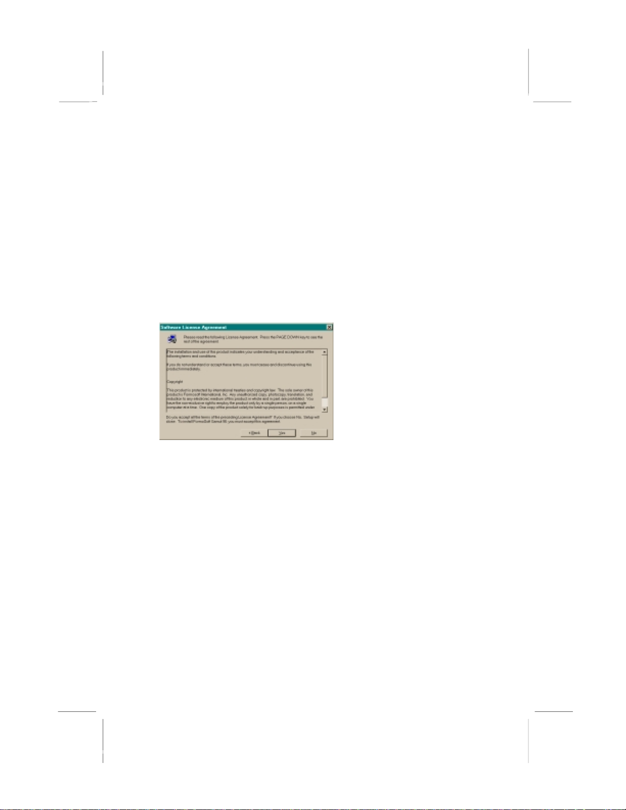
button to continue.
You will see the welcome screen of GAMUT2000. Click the
If you accept the terms of the license agreement, click Yes
3. Main Console
3.1 Introduction
Main Console
controls and displays critical elements of song
playback, and especially controls are the configuration of the
Plugins
functions on music playback.
and
Skins
of
LifeAmp
. This chapter describes the control
3.2 Function and Operation
The four buttons on the
Minimize, and
Plugins
options as below illustrator.
Main Console
of
LifeAmp
are Open, Exit,
A9
Page 52
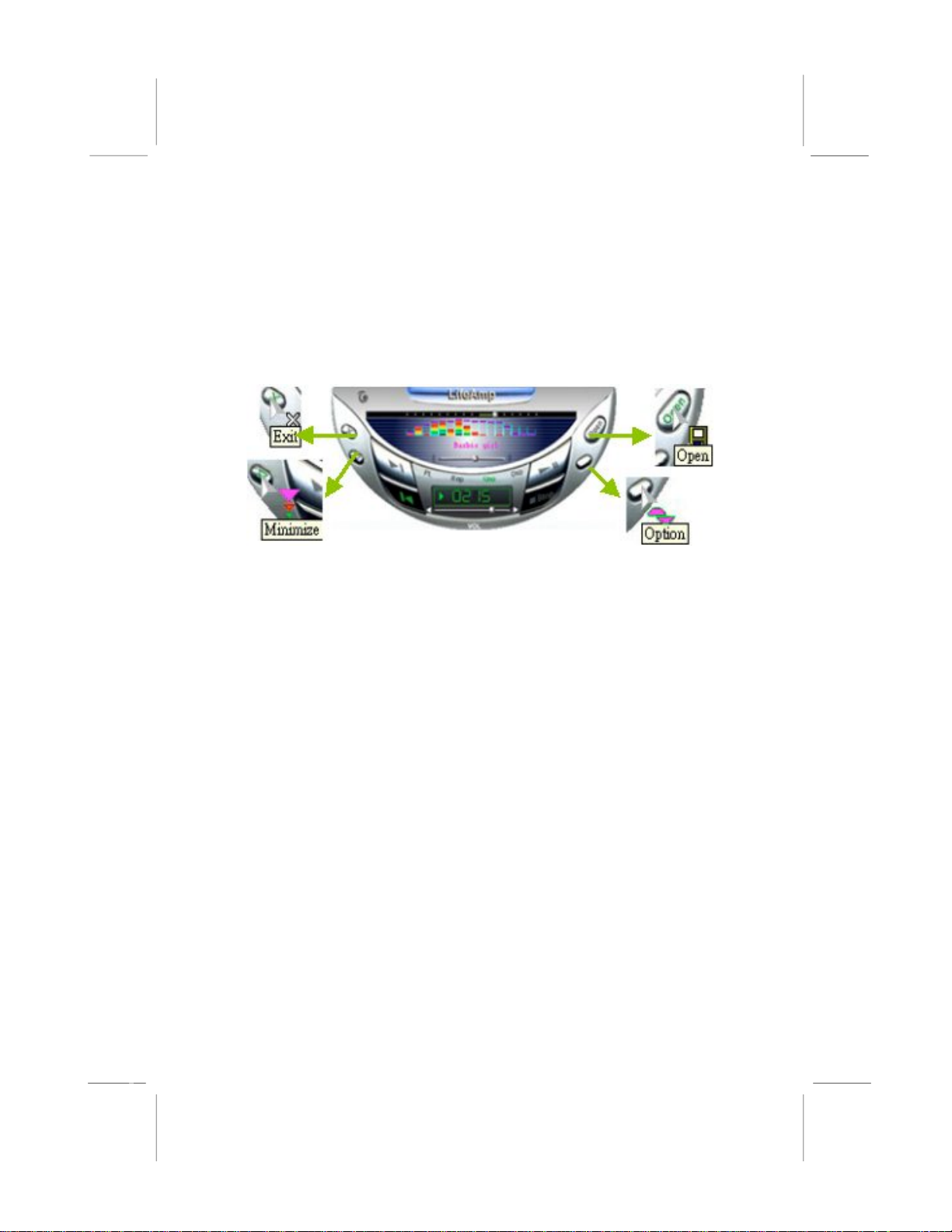
Open: Open new files.
•
Option: Activate the menu of Plugin Options.
•
Exit: Exit LifeAmp.
•
Minimize: Minimize the screen of Main Console on the task bar.
•
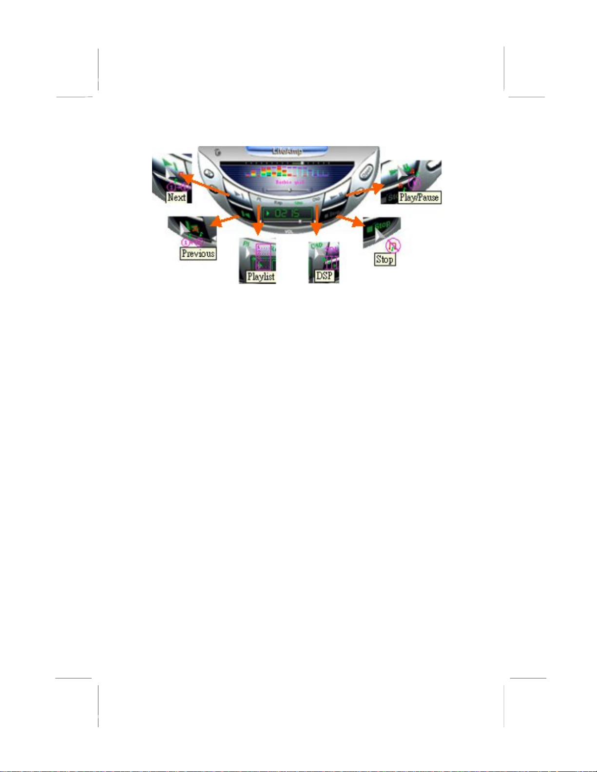
As below illustrator, the control over playback of music is through
following button:
DSP: Activate the DSP Console.
•
Playlist: Activate the Playlist Console.
•
Stop: Stop the music playback.
•
Previous: Play the previous audio file or track.
•
Play/Pause: Play/Pause the music playback.
•
Next: Play the next audio file or track.
•
A10
Page 53
The music message in below illustrator shows the status of music
playback. The information includes music length, title name, music
process, volume control, balance control, shuffle and repeat
playback as explained below:
Shuffle: Set up the music playback sequence. When the shuffle is on,
•
all music is playing in a random order.
Repeat: Decide whether or not the music sequences should be
•
repetitively playback.
Music playback progress: Show the progress status of music playback.
•
There are two display manners: one for the progress length and
another for the residual length. Clicking the number display on the
screen can toggle the two displays.
Title Name: display the file name of title name of the playback file.
•
Volume control: Control the volume of the playback.
•
Balance control: Control the volume balance between the left and the
•
right channe ls.
Position: Display the music playback status on the total length bar.
•
About: About LifeAmp.
•
A11
Page 54
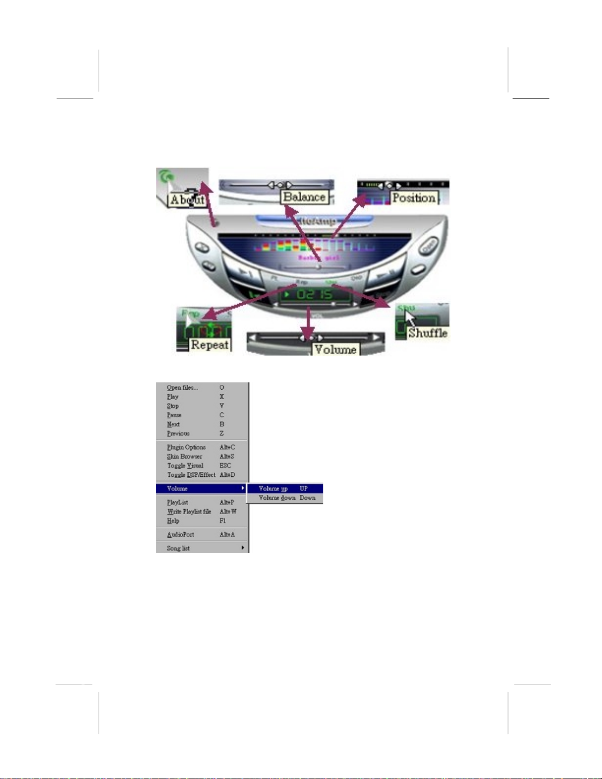
Figure 1: Right-bottom activated menu of LifeAmp.
A12
Page 55

3.3 Main Menu
The buttons on
function can be referred from the
LifeAmp
items in the menu can be used to control the playback and the
configuration of
menu.
is activated by right button of the mouse. The function
Main Console
LifeAmp
are the basic functions. Advanced
Main Menu. Main Menu
. Table 1 illustrates the hot key used in the
of
A13
Page 56
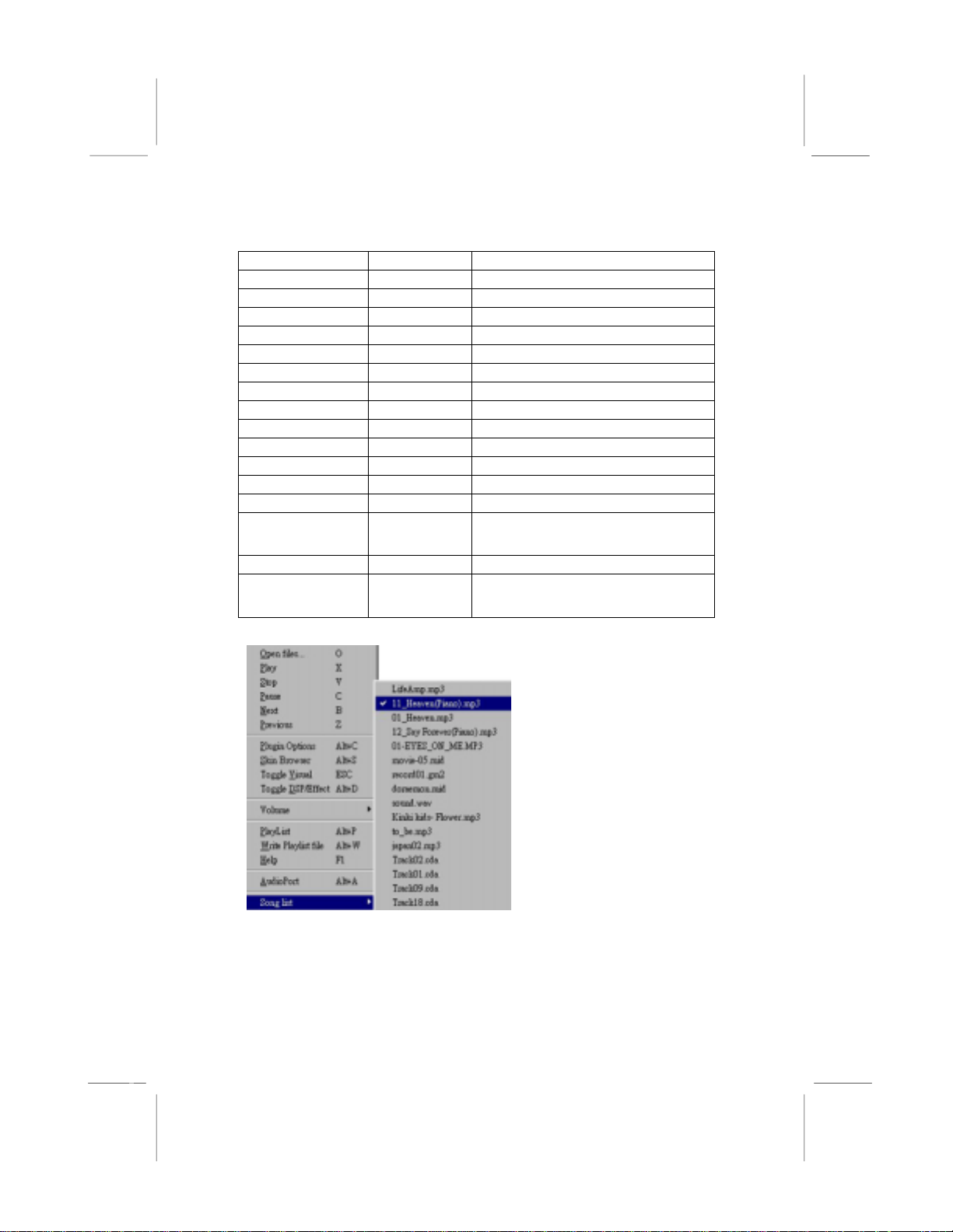
Table 1. Shortcut for LifeAmp Main Console
y
Functions Hot Ke
Open Files… O Open the new files.
Play X Play the current song.
Stop V Stop the playback.
Pause C Pause the playback.
Next B Playback next song.
Previous Z Playback last song.
Plugin Options Alt + C Open Main Menu.
Skin Browser Alt + S Activate the Skin browser.
Toggle Visual ESC
Toggle DSP/Eff. Alt + D
Volume Up Up Arrow Increase Volume.
Volume Down Down Arrow Decrease Volume.
PlayList Alt + P
Write Playlist
file
Help F1 LifeAmp on-line user’ guide.
Song list - Show the song sequences of the
Alt + W Save the music sequences in
Turn on/off the
Turn on/off
Activate
Playlist into a file.
Playlist as shown in Figure 2.
Description
Visual Plugin
DSP Plugin.
Playlist Console.
.
Figure 2: Song List
A14
Page 57

See detail of Gamut 2000 manual file within your product driver CD.
A15
 Loading...