

Page 1

Important Information
Copyright
This publication, including all photographs, illustrations and software, is
protected under international copyright laws, with all rights reserved.
Neither this manual, nor any of the material contained herein, may be
reproduced without the express written consent of the manufacturer.
Disclaimer
The information in this document is subject to change without notice. The
manufacturer makes no representations or warranties with respect to the
contents hereof and specifically disclaims any implied warranties of
merchantability or fitness for any particular purpose. Further, the
manufacturer reserves the right to revise this publication and to make
changes from time to time in the content hereof without obligation of the
manufacturer to notify any person of such revision or changes.
Trademark Recognition
Microsoft, MS-DOS and Windows are registered trademarks of Microsoft
Corp.
MMX, Pentium, Pentium-II, Pentium-III, Celeron are registered
trademarks of Intel Corporation.
VGA, OS/2, PS/2 are registered trademarks of International Business
Machines.
AMD, K5, K6 are registered trademarks of Advanced Micro Devices Inc.
Cyrix, M1 are registered trademarks of Cyrix Corporation.
Other product names used in this manual are the properties of their
respective owners and are acknowledged.
Version 3.0
Page 2

Safety Compliance
Federal Communications Commission (FCC)
This equipment has been tested and found to comply with the limits for a
Class B digital device, pursuant to Part 15 of the FCC Rules. These
limits are designed to provide reasonable protection against harmful
interference in a residential installation. This equipment generates, uses,
and can radiate radio frequency energy and, if not installed and used in
accordance with the instructions, may cause harmful interference to
radio communications. However there is no guarantee that interference
will not occur in a particular installation. If this equipment does cause
harmful interference to radio or television reception, which can be
determined by turning the equipment off and on, the user is encouraged
to try to correct the interference by one or more of the following
measures:
! Reorient or relocate the receiving antenna.
! Increase the separation between the equipment and the receiver.
! Connect the equipment onto an outlet on a circuit different from that
to which the receiver is connected.
! Consult the dealer or an experienced radio/TV technician for help.
Shielded interconnect cables and shielded AC power cable must be
employed with this equipment to insure compliance with the pertinent RF
emission limits governing this device. Changes or modifications not
expressly approved by the system’s manufacturer could void the user’s
authority to operate the equipment.
Declaration of Conformity
This device complies with part 15 of the FCC rules. Operation is subject
to the following conditions:
! This device may not cause harmful interference, and
! This device must accept any interference received, including
interference that may cause undesired operation.
Canadian Department of Communications
This class B digital apparatus meets all requirements of the Canadian
Interference-causing Equipment Regulations.
Cet appareil numérique de la classe B respecte toutes les exigences du
Réglement sur le matériel brouilieur du Canada.
Page 3

Contents
Chapter 1: Introduction
Welcome .......................................................................1
About the Manual..........................................................2
Checklist........................................................................2
Features........................................................................3
Chapter 2: Installation
Before You Begin..........................................................6
Mainboard Guide...........................................................7
I/O Ports Side View.......................................................8
Preparing the Mainboard...............................................9
Install the Mainboard in the System Case ....................17
Make the External Connections....................................22
Chapter 3: Setup
About the Setup Utility...................................................23
Standard CMOS Setup Option......................................25
BIOS Feature Setup Option..........................................26
Chipset Features Option ...............................................29
Power Management Setup Option................................31
PNP/PCI Configuration Option......................................34
Load BIOS Defaults Option...........................................36
Load Setup Defaults Option .........................................36
Integrated Peripherals Optio n.......................................36
Supervisor and User Password Settings ......................39
IDE HDD Auto Detection Option...................................40
Save And Exit Setup Option .........................................40
Exit Without Saving Option ...........................................40
Chapter 4: Software
About the Software........................................................41
Running the Support CD-ROM.....................................43
Utility Folder Insatllation Note .......................................43
CMI8338 Audio Folder Installation Note .......................44
VIA Folder Installation Note..........................................45
Mainboard Installation Notes ........................................47
Appendix 1: Quick Jumper Setting Reference..............48
Page 4

CChhaapptteerr 11:: IInnttrroodduuccttiioon
n
Welcome
Congratulations on your purchase of the MS7102C mainboard. This
mainboard features the latest VIR ET82C693/596A chipset. This is a
very special mainboard which allows you to install almost any kind of
Intel Pentium-II/III processor. The MS7102C is a full-sized ATX board
measuring 305x220mm and using 4-layer printed circuit board.
The MS7102C has a special design feature so that it includes a PentiumII Slot-1 processor slot and a PPGA (Plastic Pin Grid Array) Celeron
Socket-PGA370 processor socket. This feature means that you can
install the mainboard with either a Pentium-III cartridge, a PentiumII cartridge, the SEPP (Single Edge Processor Package) Celeron
cartridge, or one of the new generation PPGA Celeron cartridges.
In addition, the mainboard supports a 66 MHz memory bus, or a 100
MHz memory bus, so you can use inexpensive 66MHz memory chips, or
higher-performance PC-100 memory chips. The board is installed with
an integrated PCI-3D sound system and has a full suite of I/O ports.
Seven expansion slots are available for system development and
hardware monitoring is supported.
This board allows complete flexibility. System integrators can choose the
high-performance Pentium-II processor cartridge or the inexpensive
PPGA Celeron processor according to the system requirements and the
price/performance comparison of the two kinds of processor.
This chapter contains the following information:
! About the Manual explains how the information in this manual is
organized
! Checklist comprises a list of the standard and optional components
that are shipped with this mainboard,
! Features highlights the functions and components that make this
one of the best value mainboards on the market
1
Page 5

About the Manual
The manual consists of the following chapters:
Introduction
Use the Introduction Chapter to learn about the features of the
mainboard, and the checklist of items that are shipped with the package.
Installation
Use the Installation Chapter to learn how to install the mainboard and
get your system up and running.
Setup
Use the Setup Chapter to configure the mainboard for optimum
performance.
Software
Use the Software Chapter to learn how to use the software drivers and
support programs that are provided with this mainboard.
Checklist
Compare the contents of your mainboard package with the standard
checklist below. If any item is missing or appears damaged, please
contact the vendor of your mainboard package.
Standard Items
1 x MS7102C Mainboard
""""
1 x Cable/Bracket Pack
""""
Diskette drive ribbon cable
IDE drive ribbon cable
This User’s Manual
""""
Software Support CD-ROM Disc
""""
Optional Items
1 x V 9.0 Fax/Modem Card
2
Page 6

Features
The key feature of this mainboard is the dual processor sockets which
allow you to install any of the Pentium-III and Pentium-II processors
including Slot1 cartridges SE PP Celer ons and P PG A Celer ons . In
addition, this is a full-sized ATX mainboard with a full set of expansion
slots for maximum development potential.
Support for Pentium-III/Pentium-II Cartridges or PPGA Celeron
The principal feature of this mainboard is that it can support three kinds
of processors: Pentium-III cartridges, Pentium-II cartridges and SEPP or
PPGA Celerons. Pentium-III cartridges feature 512K of level-2 cache
memory with improved instructions to handle 3D audio and video.
Speech recognition, MPEG2 motion picture encoding/decoding, and
TCP/IP internet connections. The Pentium-III runs over a 100 MHz
system bus and operate at clock speeds from 450 MHz up to 550 MHz
or more.
The Pentium-II cartridges are very powerful processors which include
32K of internal level-1 cache memory and 512K of external level-2 cache
memory. The first generation of Pentium-II cartridges ran over a 66 MHz
system bus, but current Pentium-II cartridges run over a 100 MHz
system bus and operate at clock speeds from 350 MHz up to 450 MHz
or more. The slot-1 processor can also be used by the SEPP Celeron
processors which can operate over a 66/100 MHz system bus and
operate at clock speeds up to 466 MHz.
The new generation PPGA Celeron processors ship in the familiar
square plastic package, and they install in a Zero Insertion Force (ZIF)
socket called a Socket-370. The new Celeron processors are close to
Pentium-II performance because they include a level-2 cache memory of
128K. However, they operate at a 66/100 MHz system bus and they
currently ship a clock speeds of 466 MHz.
System assemblers can install either a Pentium-III or Pentium-II
cartridge or the SEPP Celeron in the slot-1 processor slot. Alternatively,
they can install a second generation PPG A Celer on in the Soc k et- 370
processor socket. Assemblers can choose the processor they need to
meet performance or price targets. You can configure the system for any
of the supported processor clock speeds using the BIOS setup utility. It
is not necessary to set switches or jumpers.
3
Page 7

Choice of Memory Options
The board has three DIMM slots for the installation of 168-pin, 3.3V
standard or registered SDRAM (Synchronous Dynamic Random Access
Memory) memory modules. The system supports memory that has builtin error correction (EC), error correction code (ECC), or has no error
correction.
If you are using a Pentium-III/PentiumII processor cartridge that operates
over a 100 MHz system bus, you must install PC-100 compliant memory
modules (memory that operates at 100 MHz). If you install the PPGA
Celeron processor, you can install memory that operates at 66 MHz (you
can install PC-100 memory if you wish, but the system will run the
memory at 66 MHz).
You can install one, two or three modules. Each memory module can
hold a maximum capacity of 128 MB of standard SDRAM chips, or 256
MB of registered SDRAM chips so maximum memory capacity is 384
MB of standard SDRAM memory or 768 MB registered SDRAM memory.
Highly Integrated Design
This board uses the VIR ET82C693/596A chipset. The ET82C693 forms
the north bridge and supports system buses of 66 and 100 MHz. It is
AGP Rev. 1 compliant and supports 3.3v AGP devices operating over a
66/133 MHz bus. The memory bus supports the fastest access (X-1-1-1)
for both 66 MHz and 100MHz operation. The board is compliant with PCI
Rev.2.1 operating at 33 MHz Four PCI Bus m aster s are support ed.
The south bridge is provided by the 596A. This chip supports ACPI
(Advanced Configuration and Po wer Interf ac e) Rev 1.0, onboard PCI
IDE channels, USB ports, and a System Management Bus for OS control
and configuration of devices.
Built-in PCI 3D Sound
The PCI Audio CMI 8738 is a single chip solution for PCI-bus 3D audio.
The chip provides Sound Blaster 16-bit-compatible audio, plus support
for Microsoft’s DirectSound 3D specification and Aureal A3D interface.
The sound ports include jacks for speakers, microphone and stereo in,
and a game/MIDI port. The audio system supports full duplex operation
and drivers are available for WIN 95/98 and WIN NT 4.0. The audio
system can output sound to 4 loudspeakers and also supports SPDIF
24-bit digital sound input and output.
Optional Built-in Communications
The mainboard has an integrated fax/modem connector. As an option,
you can purchase a fax/modem extension bracket which connects the
4
Page 8

line and telephone RJII sockets to the board. The fax/modem supports
the V.90 protocol that allows transmissions at up to 56Kbps and is fully
compatible with earlier transmission and error correction standards. It
supports automatic fall back and caller ID.
Maximum Expansion Options
This is a full-sized ATX mainboard that offers the maximum in system
expansion. The board has a total of 7 expansion slots. The AGP slot can
be used by an AGP graphics adapter. The four 32-bit PCI slots can be
used by PCI expansion cards, and the two 8/16-bit ISA slots can be used
by legacy ISA expansion cards. One of the PCI slots is shared with one
of the ISA slots. This means that you can use either one of these slots
but not both at the same time. With six usable slots, this mainboard can
be installed with a full set of optional expansion cards.
Integrated I/O
Using the Winbond W83977EF-AW I/O chip and the Intel BX chipset, the
board has a comprehensive set of integrated I/O ports. The I/O port
array features PS/2 keyboard and mouse ports, a parallel port, two USB
ports, two serial ports, a monitor port, a game/MIDI port, and three audio
jacks. Optionally, you can use the built-in mainboard header to add in an
infrared port. The mainboard has two PCI-IDE channels and a floppy
disk drive interface.
Hardware Monitoring
The mainboard is installed with the GL520SM hardware monitoring chip.
Using this chip and the monitoring software supplied with the system,
users and system administrators can monitor critical parameters such as
the CPU temperature, the fan speeds and so on. Hardware monitoring
helps maintain the system and reduce maintenance costs and downtime.
Keyboard Power On Feature
Using the system BIOS setup program, you can configure the system to
turn on using a keyboard-typed password or hot key. A green keyboard
is not required.
Programmable Firmware
The mainboard includes Award BIOS that allows BIOS setting of CPU
parameters. The fully programmable firmware enhances the system
features and allows users to set power management, CPU and memory
timing, LAN and modem wake-up alarms, and so on. The firmware can
also be used to set parameters for different processor clock speeds so
that you don’t need to change mainboard jumpers and switches.
5
Page 9

CChhaapptteerr 22:: IInnssttaallllaattiioon
n
Before You Begin
Before you begin to install your MS7102C mainboard, take some
precautions to ensure that you avoid the possibility of damage to the
product from static electricity. Ensure too that you are installing the
mainboard into a suitable case.
Static Electricity
In adverse conditions, static electricity can accumulate and discharge
through the integrated circuits and silicon chips on this product. These
circuits and chips are sensitive and can be permanently damaged by
static discharge.
♦
If possible wear a grounding wrist strap clipped to a safely
grounded device during the ins ta lla tio n.
♦
If you don’t have a wrist strap, discharge any static by touching
the metal case of a safely grounded device before beginning the
installation.
♦
Leave all components inside their static-proof bags until they are
required for the installation procedure.
♦
Handle all circuit boards and electronic components carefully.
Hold boards by the edges only. Do not flex or stress circuit
boards.
Choosing a Case
The MS7102C mainboard complies with the specifications for a full-sized
ATX board. Make sure that your system case supports a full-size ATX
board and has a power supply unit for all the expansion potential of the
system.
Some features on the mainboard are implemented by cabling connectors
on the mainboard to indicators and switches on the system case. Ensure
that your case supports all the features required. The MS7102C
mainboard can support one or two floppy diskette drives and four
6
Page 10
enhanced IDE drives. Ensure that your case has sufficient power and
space for all the drives that you intend to install.
The mainboard has a set of I/O ports on the rear edge. Ensure that your
case has an I/O template that supports the I/O ports and expansion slots.
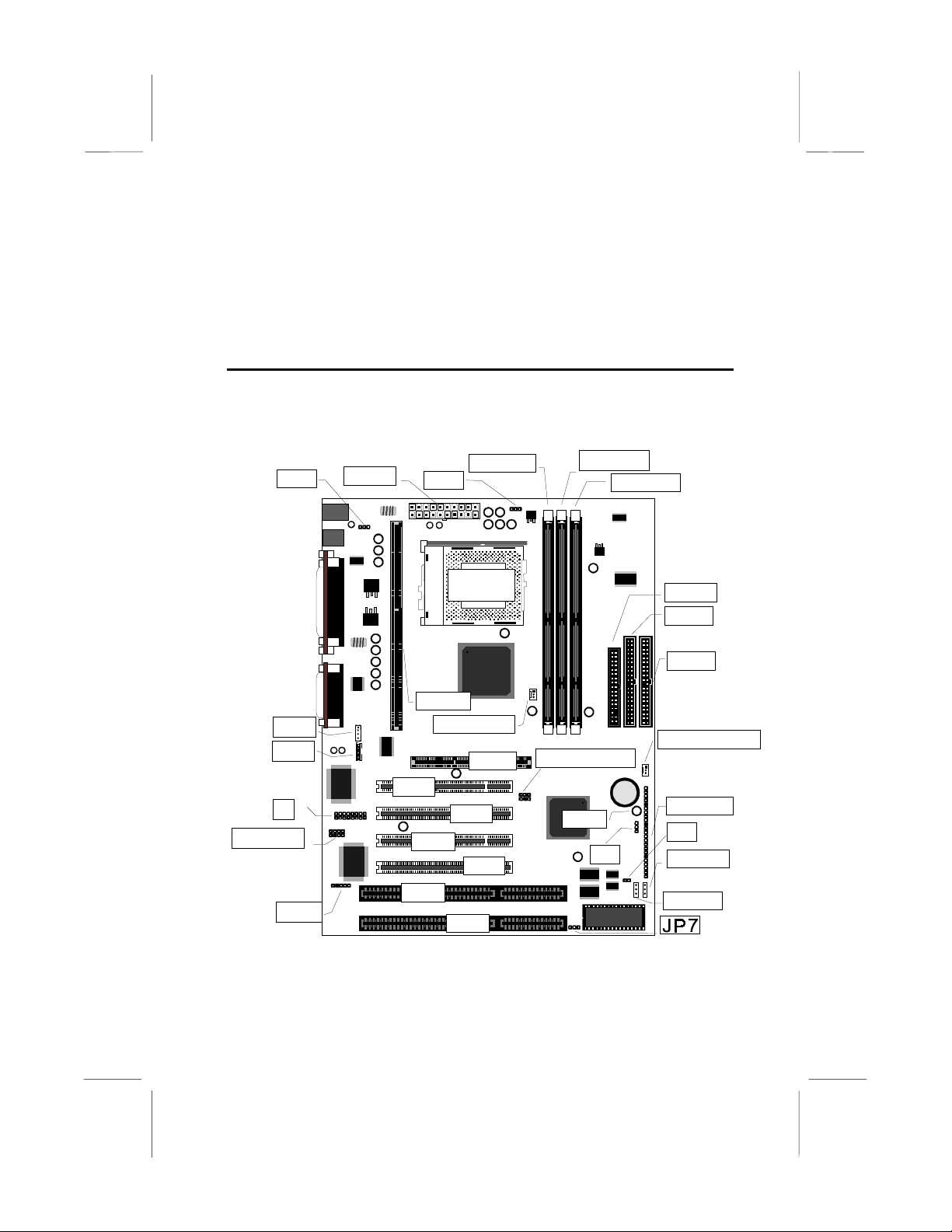
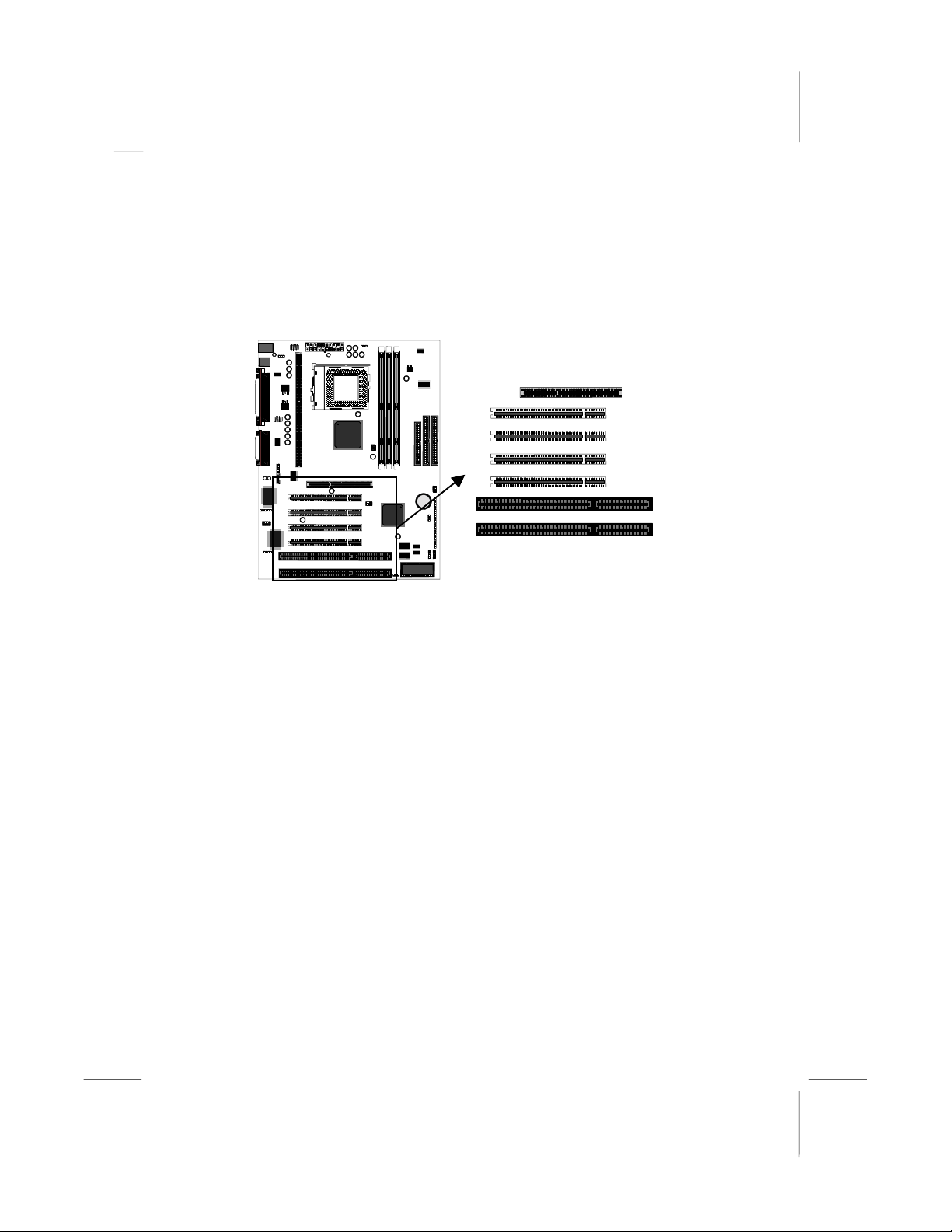
Mainboard Guide
Use the following illustration and key to identify the components on your
mainboard.
JP2
CD1
CD2
J1
SPDIF1
SIR1
ATX 1
SLOT1
PCI1
PCI3
ISA1
DIMM1
JP4
SOCKET
PGA370
CPUFAN1
AGP1
PCI2
PCI4
ISA2
DIMM2
DIMM3
SIDEBAND1
LED1
JP1
FDD1
ID E 2
ID E 1
CASEFAN1
PA NE L
J2
WOM1
WOL1
7
Page 11

Key to Mainboard Components
Component Description
ISA1,2 2 x 8/16-bit ISA expansion slots
AGP1 AGP graphics adapter slot
PCI 1,2,3,4 4 x 32-bit PCI expansion slots
SOCKET PGA370 Processor socket for PPGA Celeron processor
SLOT1 Slot for Pentium-II/III processor or SEPP Celeron processor
DIMM1,2,3 Slots for 168-pin memory modules
FDD1 Connector for floppy disk drives
IDE1, IDE2 Primary and secondary IDE channels
ATX1 Connector for ATX power supply
SIR1 Connector for optional IR port
PANEL Panel connector for switches and indicators
CPUFAN1 Power connector for CPU cooling fan
CASEFAN1 Power connector for case cooling fan
WOM1 Connector for modem wake up
WOL1 Connector for LAN wake up
SPDIF1 SPDIF In/out connector (24-bit digital audio interface)
SIDEBAND1 SB-Link connector for Sound Blaster audio card
CD1 Audio connector for optional CD-ROM drive
CD2 Auxiliary audio connector for optional CD-ROM drive
J1 Connector for fax/modem Adapter Card
J2 Head for Indicator lamp for Suspend to RAM
JP1 Clear CMOS memory jumper
JP2 Keyboard power on jumper
JP4 System Bus Frequency Selector
JP7 Flash BIOS enable/disable jumper
LED1 Suspension indicator
*J2
This head is for Indicator lamp for Green mode. This red indicator lamp
turns on if your computer has been suspended to RAM. In a suspend to
RAM, the system turns off most of the power-consuming components
except for the 3.3V required to refresh the memory. If the indicator lamp
is turned on, it warns you that the computer is suspended to RAM and a
refresh current is passing through the memory modules. You should not
attempt to remove or install memory modules when the indicator lamp is
turned on.
8
Page 12
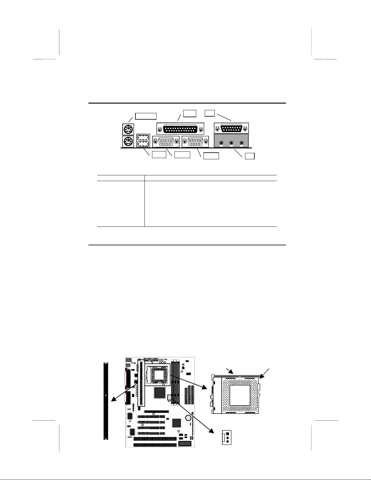
I/O Ports Side View
KBMPS2
USB1
Key to I/O Ports
Component Description
KBMPS2 PS/2 port for pointing device (upper port)
PS/2 port for keyboard (lower port)
LPT1 External parallel port
JS1 (Upper) External game/MIDI port
JS1 (Lower) Audio jacks for (left to right) line out, line in, microphone
COM2 External monitor port
COM1 External serial port 1/3
USB1 Two stacked Universal Serial Bus ports
LPT1
COM1
JS1
COM2
Preparing the Mainboard
Prepare the main board by carrying out the following steps;
♦
Install the processor
♦
Install the memory module(s)
♦
Check the jumper settings
JS1
Install the Processor
This board has a Slot1 for a processor cartridge and a socket-370 for a
PPGA Celeron processor. You can install one processor cartridge or one
PPGA Celeron. You cannot install both a slot-1 cartridge and a PPGA
Celeron.
Locate SLOT1, Socket-370 and CPUFAN1
Locking lever
Socket-370
CPUFAN1
SLOT1
Pin-1 corner
9
Page 13
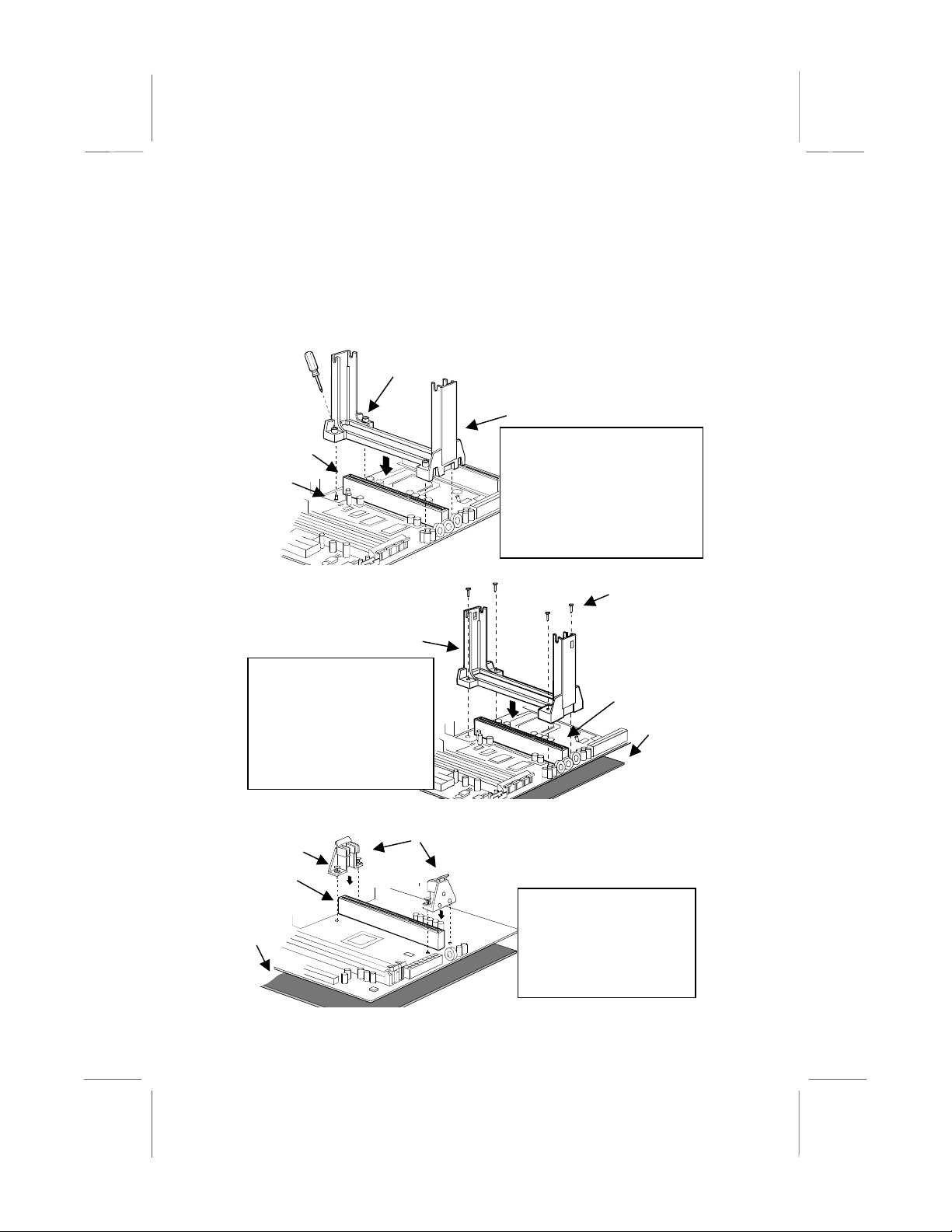
Installing a SLOT1 Cartridge Holder and Cartridge
The SLOT1 on the mainboard must be installed with a retention
mechanism to support the cartridge. The illustrations below show how to
install several different kinds of Slot1 cartridge holders.
Captive nut
Cartridge holder
Slot1
Locking
screw
Cartridge holder
This cartridge holder is in one
piece. Place the mainboard
on a plastic mat and then
secure the holder in place by
pushing the plastic pins
through the holder and
through the holes in the
mainboard.
Cartridge holders
Captive pin
Slot1
Foam
plastic
mat
This cartridge holder is in one
piece. The two upright post s may
be folded down for shipping.
Screw the captive nuts onto the
locking screws inserted in the
mainboard. Don’t overtighten the
nuts as this will stress the
mainboard.
Pins
Slot1
Foam
plastic
mat
This cartridge holder is in two
pieces. Place the mainboard
on a plastic mat and then
secure the cartridge holders
in place by pushing the
captive pins throug h the holes
in the mainboard.
10
Page 14
Some cartridge holders also include a support bar for the processor heat
sink. This bar installs to the side of the cartridge holder. Some processor
cartridges have support struts for the heat sink which lock into the
support bar. The documentation supplied with the processor shows hot
to do this.
After you have installed the cartridge holder, follow the instructions
supplied with the processor cartridge to insert the cartridge into the
holder. If the processor has a cooling fan, connect the power cable of the
fan to the power supply connector on the mainboard CPUFAN1.
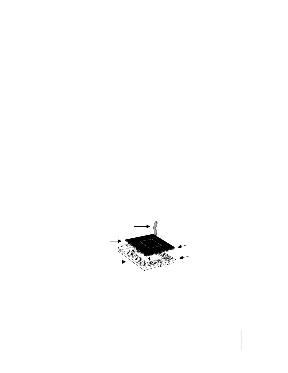
Installing a PPGA Celeron in the Socket-370
This mainboard is installed with a PGA370 ZIF processor socket. This
socket will only support the PPGA Celeron processor.
a socket-7 processor such as a Pentium or Pentium-compatible
processor
. The PPGA Celeron processors all run over a 66 MHz system
bus and have internal clock speeds ranging from 300 to 433 MHz.
Configuration of the processor is made automatically using the
mainboard BIOS (see the Setup chapter).
1. Locate the zero insertion force (ZIF) PGA370 socket for the
processor.
2. On the socket and on the processor, identify the pin 1 corner. On the
socket, the pin-1 corner is opposite the hi nge of the locking lever,
and it has one hole missing from the corner. On the processor, the
pin-1 corner has a slight bevel.
Do not try to insert
Locking lever
Celeron processor
Socket-370
Pin-1 corner
Pin-1 corner
3. Push the socket locking lever away from the socket to unhook it.
Swing the lever into the upright posit ion .
4. Insert the processor into the socket taking care that you have
matched the pin 1 corners. No force is required, and the processor
should seat smoothly into the socket.
11
Page 15
5. Swing the locking lever down and hook it under the latch on the side
of the socket to lock it in place.
6. Locate the power connector for the processor cooling fan CPU FAN1.
If your processer has a cooling fan installed, connect the cable from
the cooling fan to CPU FAN1.
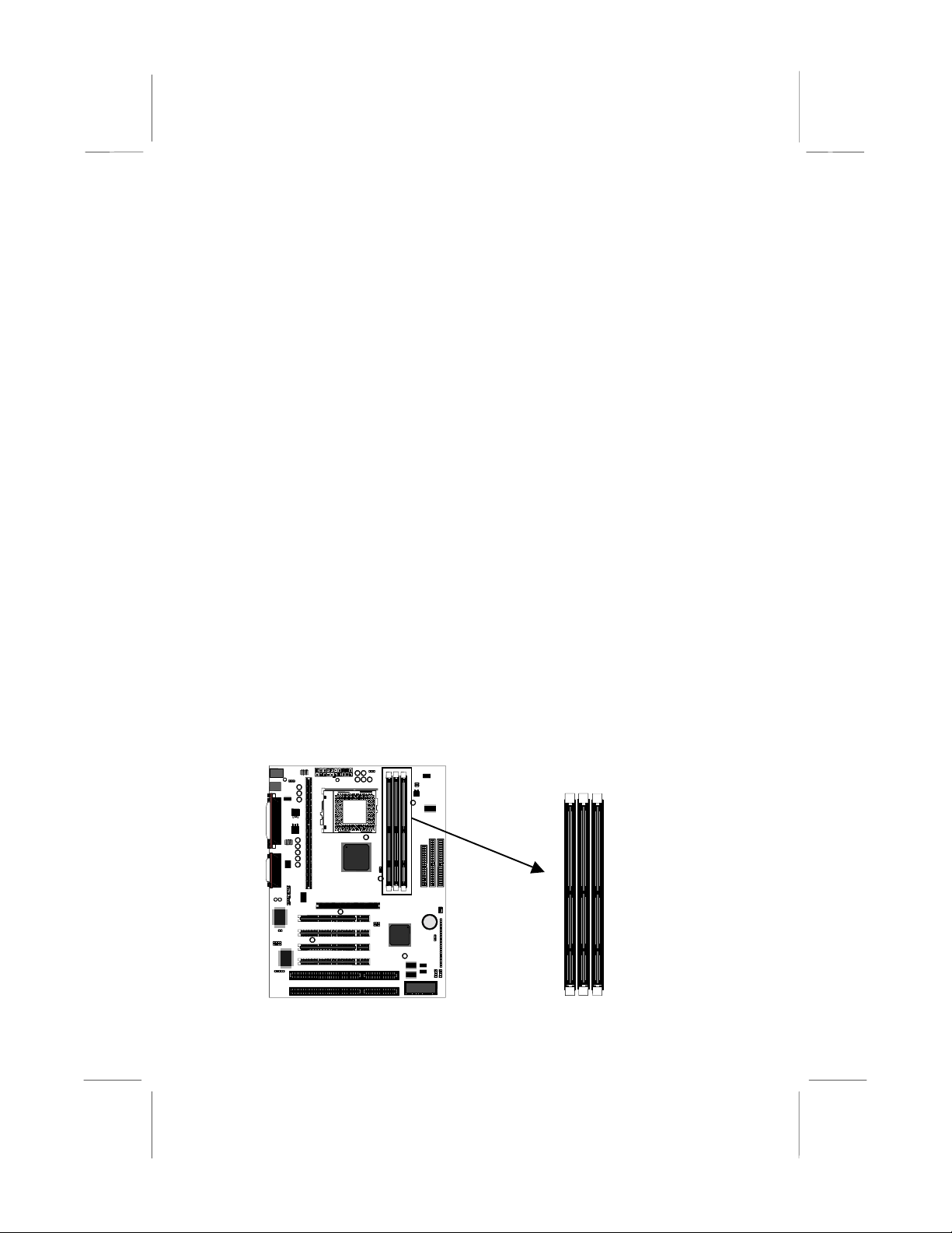
Install the Memory Modules
For this mainboard, you must use 168-pin 3.3V non-buffered Dual In-line
Memory Modules (DIMMs). The memory chips must be standard or
registered SDRAM (Synchronous Dynamic Random Access Memory).
The memory bus can run at 66 MHz or 100 MHz. If your processor
operates over a 100 MHz system bus, you must install PC-100 memory
that also operates over a 100 MHz bus. If you install a processor that
operates over a 66 MHz bus, you can install memory chips that operate
at 66 MHz.
You must install at least one memory module and the first memory
module should be installed in slot DIMM1, the second in slot DIMM2 and
the third in slot DIMM3. If the modules use standard SDRAM, the
maximum capacity of each module is 128K. if the modules use
registered SDRAM, the maximum capacity is 256K.
The mainboard supports memory chips that have EC (Error Correction)
or ECC (Error Correction Code). If you install more than one module, the
modules should can have different capacities, but the memory chips
should all be the same type.
1. Locate the DIMM slots on the mainboard.
12
DIMM1
DIMM2
DIMM3
Page 16
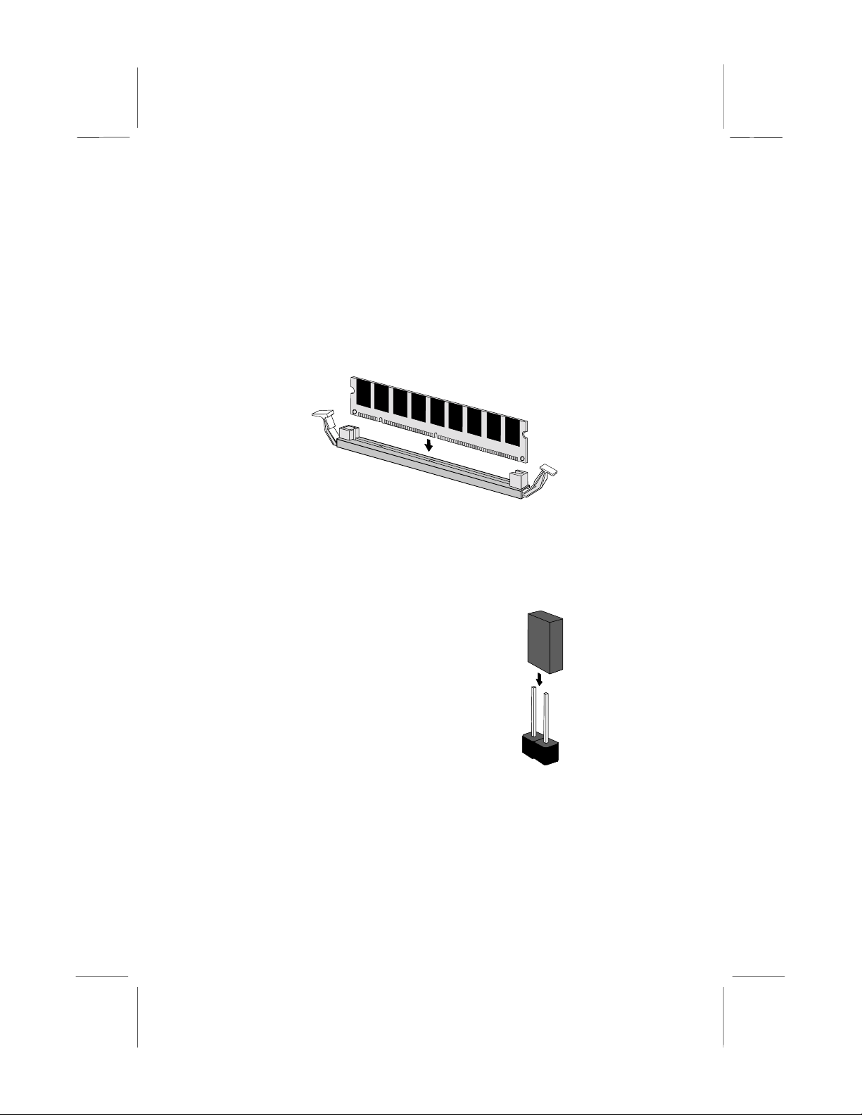
2. The DIMM slots are keyed with notches and the DIMMs are keyed
with cut-outs so that they can only be installed correctly. Check that
the cut-outs on the DIMM module edge connector match the notches
in the DIMM slot.
3. Push the latches on each side of the DIMM slot down.
4. Install the DIMM module into the slot and press it carefully but firmly
down so that it seats correctly. The latches at either side of the slot
will be levered upwards and latch on to the edges of the DIMM when
it is installed correctly.
Check all the Jumper Settings
Check all the mainboard jumpers to ensure that the board is configured
correctly.
A Note on Jumpers
A jumper consists of two or more pins mounted
on the mainboard. Some jumpers might be
arranged in a series with each pair of pins
numbered differently. Jumpers are used to
change the electronic circuits on the mainboard.
When a jumper cap is placed on two jumper
pins, the pins are SHORT. If the jumper cap is
removed (or placed on just a single pin) the
pins are OPEN.
Jumper cap
2-pin jumper
13
Page 17

JP2
JP4
JP1
J1
JP7
JP1: Clear CMOS Memory Jumper
This jumper lets you erase the system setup settings that are stored in
CMOS memory. You might need to erase this data if incorrect settings
are preventing your system from operating. To clear the CMOS memory,
turn off the system, disconnect the power cable from the mainboard, and
short the appropriate pins for a few seconds.
JP1
3
Function Jumper Cap
Normal Operation Short pins 1-2
2
Clear CMOS Short pins 2-3
1
JP2: Keyboard Power On Jumper
This jumper lets you use a typed-in password as a power switch to turn
your system on. If you enable this property, you need to define the
password or the hot keys using the setup utility. See Chapter 3 for more
information.
Function Jumper Cap
Disable keyboard power on Short pins 1-2
Enable keyboard power on Short pins 2-3
1 2 3
JP2
14
Page 18

JP4: System Bus Frequency Select Jumper
Use this jumper to select a system bus frequency of either Normal or 100
MHz. If Normal, the system automatically selects 66 or 100 MHz,
according to the installed processor. If 100 MHz, the system will force a
system bus of 100 MHz no matter what kind of processor is installed.
Function Jumper Cap
Normal Short pins 1-2
Force 100 MHz Short pins 2-3
1 2 3
JP4
JP7: Flash BIOS Enable/Disable Jumper
The mainboard BIOS is stored on an Erasable Programmable Read Only
Memory (EPROM) chip. This means that you can erase the current BIOS
and install an updated BIOS whene ver new upgrades are released. See
Chapter 4 for information on using the Flash BIOS utility. Before erasing
the old BIOS and flashing a new BIOS, you must set JP7 to Enable.
After the new BIOS is installed, set JP7 to Disable so that the BIOS
cannot be erased by accident.
Function Jumper Cap
Enable flash BIOS Short pins 1-2
Disable flash BIOS Open pins 2-3
1 2 3
JP7
15
Page 19
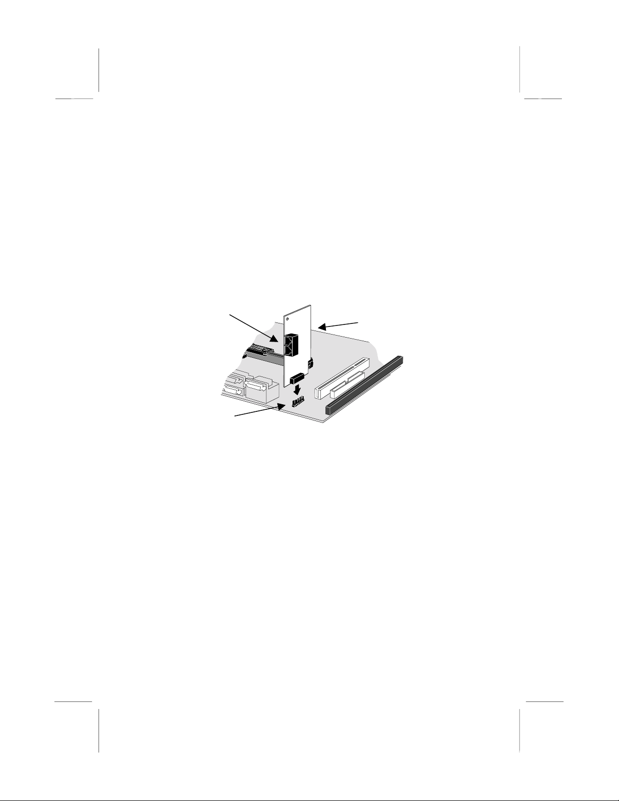
J1: Fax/modem Extension Bracket
The fax/modem extension bracket is supplied with this mainboard.
1. Locate the J1 fax/modem connector on the mainboard.
2. Remove the expansion slot blanking plate from the system chassis
that is adjacent to the fax/modem connector.
3. Install the fax/modem extension bracket on to the MDM1 connector
as shown below. The RJ11 Line and Telephone sockets on the
bracket are positioned in the expansion slot with the removed
blanking plate.
Line and Tel
RJ11 sockets
J1
fax/modem
connector
Fax/modem
extension bracket
16
Page 20
Install the Mainboard in the System Case
Use the screws and mounting brackets supplied with your system case
to install the mainboard. Follow the instructions provided by the case
manufacturer.
Connect Devices, Switches and Indicators
Note:
You might not need to carry out every step in the following
procedure. It depends on the options you are installing, and the
features that are supported by your system case.
Note:
Ribbon cable connectors are usually keyed so that they can
only be installed correctly on the device connector. If the
connector is not keyed make sure that you match the pin-1 side of
the cable connector with the pin-1 side of the device connector.
Each connector has the pin-1 side clearly marked. The pin-1 side
of each ribbon cable is always marked with a red stripe on the
cable.
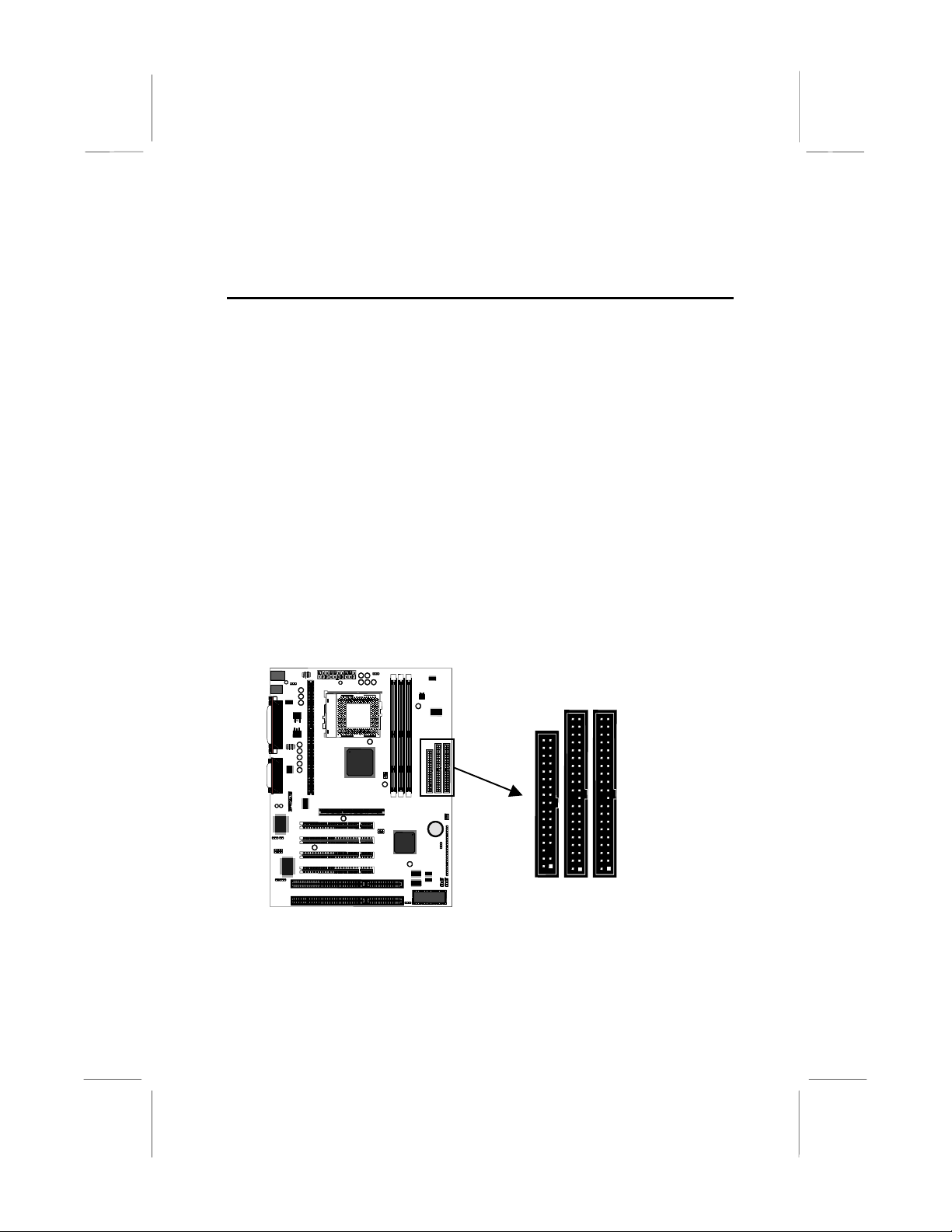
IDE & FDD Drives
IDE2
IDE1
FDD
1. Locate the floppy diskette drive connector FDD1. Use the ribbon
cable to connect one or two floppy diskettes to the mainboard.
2. Locate the Enhanced IDE connectors IDE1 (primary) and IDE2
(secondary). A single IDE cable is provided with the mainboard.
Connect the cable to IDE1. The cable has two connectors for IDE
17
Page 21

devices. If you connect two devices, you must configure one device
as Master, and one device as Slave. See the documentation
provided with the devices for information on this. To install more
drives, use another IDE cable and connect one or two devices to
IDE2.
Power Connector, Panel Connector & Case Fan
CASEFAN1
ATX1
PANEL
1. Locate the power connector ATX1. Connect the power cable from
the power supply unit to ATX1. The connector is keyed so that it can
only be installed correctly.
2. If your system case has a built-in cooling fan, you can supply power
to the fan from the case fan power connector CASEFAN1. Connect
the power cable from the fan to CASEFAN1.
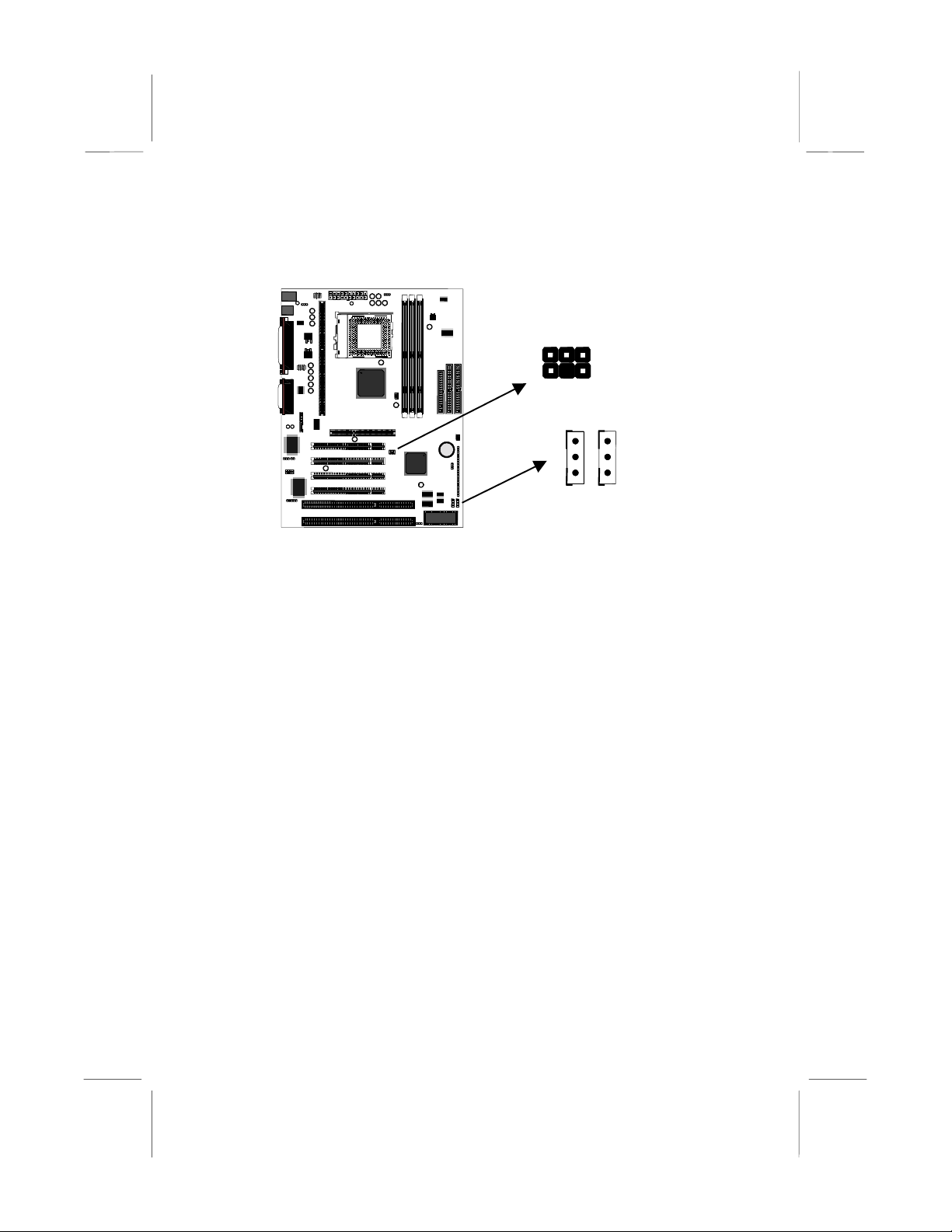
3. Locate the bank of switch and indicator
connectors PANEL. These connectors
provide control functions to your system
case. Use the illustration on the right and
PANEL
23
Power SW 22-23
HDD LED 20-21
the table below to make the connections.
Speaker 15-16-17-18
Function Pins
Power Indicator 1+, 2+, 3
Sleep Switch 4, 5
Green Indicator 7+, 8+, 9
Keylock 10, 11
Reset Switch 12, 13
Speaker 15+, 16, 17, 18
Hard Disk Indicator 20+, 21
Power Switch 22+, 23
Reset SW 12-13
KeyLock 10,11
Green LED 7-8-9
Sleep SW 4-5
Power LED 1-2-3
1
18
Page 22

Audio Connectors & Infrared Connector
CD1
2R-AUXIN
6 G N D
8 G N D
1
+12V
L-AUXIN
SPDIF1
SP D IF IN
SPDIFOUT
CD2
SIR1
1
1. If you want to install an optional Serial Infrared Port, connect the
cable from the optional IR port to the SIR1 connector on the
mainboard.
Note:
An infrared port (SIR1) and a second serial port (COM2)
share the same resources. If you install both of these options, you
cannot use them both at the same time. Use the setup utility to
configure the system to use either the infrared port or the second
serial port. See Chapter 3 for more information .
2. The mainboard has three audio connectors. CD1 is a 4-pin audio
connector which can be used to input the audio from a CD-ROM or
DVD drive. CD2 is exactly the same, except that it supports an
alternative kind of connector. Use either CD1 or CD2 to connect your
CD/DVD drive audio output. If you have insta lled a de vice wh ich
supports 24-bit SPDIF digital audio, you can connect the device to
the SPDIF input/output connector SPDIF1.
19
Page 23
Expansion Slots
You can use the expansion slots to install expansion boards that add
new features to your system. You must install a graphics adapter in
order to use the system.
AGP1
PCI1
PCI2
PCI3
PCI4
ISA1
ISA2
1. The AGP slot can be used by a graphics adapter with an AGP edge
connector. This mainboard must be installed with a graphics adapter.
You do not need to use an AGP adapter. You can also install a
graphics adapter in a PCI slot or even an ISA slot.
2. If you have 32-bit PCI expansion cards, install them in on of the four
PCI slots. If you have 8/16-bit legacy ISA cards, you can install them
in one of the two ISA slots.
Note:
The PCI slot PCI4 and the ISA slot ISA1 are shared slots.
This means that you can use either one of these slots, but not
both of them at the same time. The two slots correspond to the
same expansion card opening in the system case.
3. When you install an expansion card, remove the blanking plate from
the case expansion card opening that corresponds to the expansion
slot on the mainboard. Fit the bracket of the expansion card into the
expansion card opening and secure it in plac e with a scre w.
20
Page 24
Wake-Up Connectors and SB-Link
SIDEBAND1
WOL1
WOM1
4. The mainboard has wake up connectors for an optional network
adapter or an optional internal fax/modem card. If you have installed
a network adapter expansion card, connect it to the wake on LAN
connector WOL1. If you have installed an inter nal fax /m odem
expansion card, connect it to the wake on modem connector WOM1.
5. If you have installed a Sound Blaster PCI audio expansion card, you
can connect it to the SB-Link connector SIDEBAND1. SB-Link
solves some of the problems that can occur with the audio system
when you play legacy DOS real-mode games with a PCI Sound
Blaster.
21
Page 25

Make the External Connections
After you have installed the mainboard, make the connections to the
external ports.
KBMPS2
USB1
1. KBMPS2 is a stack of two PS/2 mini-DIN ports. The upper port can
be used by a PS/2 mouse or pointing device. The lower port can be
used by a PS/2 keyboard.
2. LPT1 is a parallel port that can be used by printers or other parallel
communications devices. The system identifies the parallel port as
LPT1.
3. The upper 15-pin port JS1 is a game/MIDI port. You can use this
port to connect a joystick or a MIDI device to your system
4. The lower part of JS1 is three audio jacks. The left side jack is for a
stereo line out signal. The middle jack is for a stereo line in signal.
The right side jack is for a microphone.
5. COM2 is a serial port that can be used by serial devices such as a
mouse, a fax/modem and so on. This serial port is identified by the
system as COM2/4.
6. COM1 is a serial port that can be used by serial devices such as a
mouse, a fax/modem and so on. This serial port is identified by the
system as COM1/3.
7. USB1 is a stack of two Universal Serial Bus ports. Use these ports to
connect to USB devices.
LPT1
COM1
JS1
COM2
JS1
22
Page 26

CChhaapptteerr 33:: SSeettuup
p
About the Setup Utility
This chapter explains how to use and modify the BIOS setup utility that is
stored on the mainboard. The setup utility stores information about the
mainboard components, and the configuration of other devices that are
connected to it. The system uses this information to test and initialize
components when it is started up, and to make sure everything runs
properly when the system is operating.
The setup utility is installed with a set of default values. The default
values are designed to ensure that the system will operate adequately.
You will probably have to make changes to the setup utility whenever
you add new components to your system such as new disk drives. You
may be able to generate increased performance by changing some of
the timing values in the setup, but this can be limited by the kind of
hardware you are using, for example the rating of your memory chips. In
certain circumstances, the system may generate an error message
which asks you to make changes to the setup utility. This happens when
the system finds an error during the POST (power on self test) that it
carries out at start up.
Starting the Setup Utility
You can only start the setup utility shortly after the computer has been
turned on. A prompt appears on the computer display which says “Press
DEL to run Setup”. When you see this prompt, press the Delete key, and
the system will start the setup utility and display the main menu of the
utility.
Using the Setup Utility
When you press the Delete key to start setup, the main menu of the
utility appears.
The main menu of the setup utility shows a list of the options that are
available in the utility. A highlight shows which option is currently
selected. You can use the cursor arrow keys to move the highlight to
other options. When an option is highlighted, you can execute the option
by pressing the Enter key.
23
Page 27

Some options lead to dialog boxes which ask you verify that that you
wish to execute that option. You usually answer these dialogs by typing
Y for yes and N for no.
Some options lead to dialog boxes which ask for more information.
Setting the User Password or Supervisor Password have this kind of
dialog box.
Some options lead to tables of items. These items usually have a value
on the right side. The value of the first item is highlighted, and you can
use the cursor arrow keys to select any of the other values in the table of
items. When an item is highlighted, you can change the value by
pressing the PageUp or PageDown keys, or the Plus or Minus keys.
The PageUp and Plus keys cycle forward through the available values,
the PageDown and Minus keys cycle backwards through the values.
When you are in the main menu, you can exit the utility by pressing the
Escape key. You can save the current selections and exit the utility by
pressing the F10 key. You can change the color scheme of the utility by
pressing the F2 key while holding do wn the Shift key.
When you are in one of the options that displays a dialog box, you can
return to the main menu by pressing the Escape key.
24
Page 28
When you are in one of the options that displays a table of items, you
can return to the main menu by pressing the Escape key. For some
items, you can display a help message by pressing the F1 key. You can
change the color scheme of the utility by pressing the F2 key while
holding down the Shift key. You can press F5 to discard any changes
you have made and return all items to the value that they held when the
setup utility was started. You can press F6 to load the displayed items
with a standard list of default values. Yo u can pres s F7 to load the
displayed items with a high-performance list of default values.
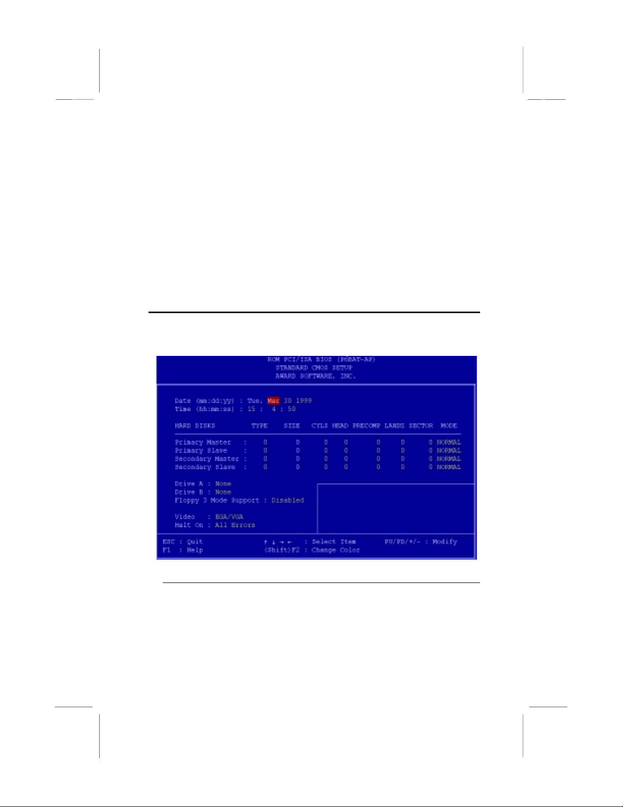
Standard CMOS Setup Option
This option displays a table of items which defines basic information
about your system.
Date and Time
The Date and Time items show the current date and time held by your computer.
If you are running a Windows operating system, these items will automatically be
updated whenever you make changes to the Windows Date and Time Properties
utility.
25
Page 29

Hard Disks Defaults: Auto
These items show the characteristics of any hard disk drives on the four
available IDE channels. (Note that SCSI hard disk drives do not appear here.)
You can automatically install most modern hard disks using the IDE HDD Auto
Detect Option from the main menu. However, if you find that a drive cannot be
automatically detected, you can use these items to select USER, and then
manually enter the characteristics of the drive. The documentation provided with
your drive provides the data you need to fill in the values for CYLS (cylinders),
HEAD (read/write heads), and so on.
The documentation provided with the drive may not tell you what value to use
under the MODE heading. If the drive is smaller than 528 MB, set MODE to
Normal. If the drive is larger than 528 MB and it supports Logical Block
Addressing, set MODE to LBA. Very few high-capacity drives do not support
Logical Block Addressing. If you have such a drive, you might be able to
configure it by setting the MODE to Large. If you’re not sure which MODE
setting is required by your drive, set MODE to Auto and let the setup utility try to
determine the mode automatically.
Drive A and Drive B Default: None , None
These items define the characteristics of any diskette drive attached to the
system. You can connect one or two diskette drives.
Floppy 3 Mode Support Default: Disabled
Floppy 3 mode refers to a 3.5” diskette with a capacity of 1.2 MB. Floppy 3 mode
is sometimes used in Japan.
Video Default: EGA/VGA
This item defines the video mode of the system. This mainboard has a built-in
VGA graphics system so you must leave this item at the default value.
Halt On Default: All Errors
This item defines the operation of the system POST (Power On Self Test) routine.
You can use this item to select which kind of errors in the POST are sufficient to
halt the system.
Base, Extended and Other Memory.
These items show how much memory is available on the system. They are
automatically detected by the system so you cannot manually make changes to
these items.
BIOS Feature Setup Option
This option displays a table of items which defines more advanced
information about your system. You can make modifications to most of
these items without introducing fatal errors to your system.
26
Page 30

CPU Internal Core Speed Default: 350MHz
This item should be installed with the rated internal core speed of the Pentium-II
class processor that is installed in your system. The setup utility will then
automatically configure the system with the correct host bus speed, and bus
frequency multiplier.
If you set this item to Manual, two new items will appear: CPU Host BUS
Frequency and CPU Core:Bus Freq. Multiple. You can use these two items to
manually configure the mainboard for the speed of the processor. The values
available in these two items will vary, according to the kind of Pentium-II
processor that is installed.
: Using the three items above, you can configure the
Note
mainboard so that it runs a processor faster than the rated clock
speed. We strongly recommend that you do not overclock the
processor. Overclocking can introduce excess heat, recurring
instability, or even complete failure in your system.
CPU Core Voltage Default: Default
This item can be used to a set a core voltage for different kinds of processors.
Leave this item at the default value and your system will automatically assign the
correct voltage.
CPU Clock Failed Reset Default: Disabled
If this item is enabled, and your system crashes three times because you have
overclocked the processor, this item will automatically adjust the speed of the
processor to the system bus speed multiplied by tw o.
27
Page 31

CIH Buster Protection Default: Enabled
Anti-Virus Protection Default: Enabled
When “CIH Buster Protection” item is enabled it provided some protection
against viruses which try to destroy BIOS viruses (especially for CIH).
When “Anti-Virus Protection” item is enabled it provides some protection against
viruses which try to write to the boot sector and partition table of your hard disk
drive. This item is Enabled as a default. You might need to disable it so that you
can install an operating system. We recommend that you enable Anti-Virus
Protection as soon as you have installed your disk with an OS.
CPU Internal Cache Default: Enabled
All the processors that can be installed in this mainboard use internal (level 1)
cache memory to improve performance. Leave this item at the default value
Enabled for better performance.
External Cache Default: Enabled
Most of the processor cartridges that can be installed in this mainboard have
(level 2) external cache memory (the Celeron-266 MHz is an exception). Only
enable this item if your processor cartridge has external cache memory.
CPU L2 Cache ECC Checking Default: Enabled
This item can be used to enable ECC (Error Checking Code) for the level-2
cache memory. We recommend that you leave this item at the default value
Enabled.
Processor Number Feature Default: Enabled
Some new procesosrs (the Pentium-III) are installed with a unique procesosr
identification number. If you disable this item, the number will be suppressed so
that it cannot be read by other systems on the network.
Quick Power On Self Test Default: Enabled
You can enable this item to shorten the power on testing and have your system
start up a little faster.
Boot from LAN First Default: Enabled
This items lets you specify that the system will try to load an operating system
from a network server first, before booting from any of the local drives.
Boot Sequence Default: A, C, SCSI
This item defines where the system will look for an operating system, and the
order of priority. You can boot an operating system from many locations
including a SCSI device, a ZIP drive, a floppy diskette drive, or an LS-120 highcapacity diskette drive.
Swap Floppy Drive Default: Disabled
If you have two floppy diskette drives in your system, this item allows you to
swap around the assigned drive letters so that drive A becomes drive B, and
drive B becomes drive A.
28
Page 32

Boot Up NumLock Status Default: On
This item defines if the keyboard Num Lock key is active when your system is
started.
Gate A20 Option Default: Normal
This option provides compatibility with older software written for the 286
processor. Leave this item at the default value Normal.
Memory Parity/ECC Check Default: Disabled
This mainboard supports memory modules that have error checking using a
parity bit, or using ECC (Error Correction Code). If your memory modules have
this function, you can enable this feature for greater reliability.
Security Option Default: Setup
If you have installed password protection, this item defines if the password is
required at system start up, or if it is only required when a user tries to enter the
setup utility.
PCI/VGA Palette Snoop Default: Disabled
This item can help overcome problems that are caused by some non-standard
VGA cards. We recommend that you leave this item at the default value Disabled.
OS Select For DRAM > 64 MB Default: Non-OS2
This item is required if you have installed more than 64 MB of memory and you
are running the OS/2 operating system. Otherwise, leave this item at the default
Non-OS2
HDD S.M.A.R.T Capability Default: Disabled
S.M.A.R.T is an industry acronym for Self-monitoring, Analysis and Reporting
Technology. If the documentation of your hard disk states that S.M.A.R.T. is
supported, you can enable this item.
Report No FDD For WIN 95 Default: Yes
When the item is enabled, the IRQ-6 can be reserved for another divice if you
don’t install FDD.
Video BIOS Shadow Default: Enabled
This item allows the video BIOS to be copied to system memory for faster
performance.
XXXXX-XXXXX Shadow Default: Disabled
These items allow the BIOS of other devices to be copied to system memory for
faster performance.
Chipset Features Option
This option displays a table of items which define timing parameters of
the mainboard components including the graphics system, the memory,
and the system logic. In general rule, you should leave the items on this
page at the default values unless you are very familiar with the technical
29
Page 33

specifications of your hardwar e. If you cha nge the values, you may
introduce fatal errors or recurring instability into your system.
Bank 0/1 DRAM Timing Default: SDRAM 10ns
Bank 2/3 DRAM Timing Default: SDRAM 10ns
Bank 4/5 DRAM Timing Default: SDRAM 10ns
These items define the timing parameters for the system memory. We
recommend that you leave these items at the default values SDRAM 10ns.
SDRAM Cycle Length Default: 3
This item sets the number of CPU cycles between SDRAM refresh. If insufficient
time is allowed, refresh may be incomplete and data can be lost . We
recommend that you leave this item at the default value.
DRAM Clock Default: Host CLK
When this item is enabled, It allows the DRAM to work concurrently with the host
bus clock, otherwise, DRAM will work concurrently with AGP clock .
Memory Hole Default: Disabled
This item can be used to reserve memory space for some ISA cards that require
it. We recommend that you leave this item at the default value Disabled.
Read Around write Default: Disabled
This item optimizes the cache memory. If the system needs to read data from an
address in memory, and the write buffer holds fresh data that has not yet been
written to that address, the read can be made directly from the write buffer,
instead of the address in the main memory.
Concurrent PCI/Host Default: Disabled
This item allows other PCI devices to work concurrently with the host PCI IDE
channel. We recommend that you leave this item at the default value Disabled.
30
Page 34

System BIOS Cacheable Default: Enabled
Video BIOS Cacheable Default: Disabled
These items allow the video and/or system to be cached in memory for faster
execution. Wee recommend that you leave these items at the default value.
Video RAM Cacheable Default: Disabled
This item permits the video memory to be cached for faster performance. We
recommend that you leave this item at the default value Disabled.
I/O Recovery Time Default: Enabled
When this item is enabled, the ISA command can be extended more than the
recovery time default 3.5 SYSCLK . We recommend that you leave this item at
the default value.
AGP Aperture Size Default: 64M
This item defines the size of the aperture for the Accelerated Graphics Port. The
aperture is a portion of the PCI memory address range dedicated for graphics
memory address space.
AGP-2x Mode Default: Enabled
This item allows the AGP graphics adapter to operate in 2x Mode. We
recommend that you leave this item at the default value Enabled.
On Board Sound Default: Enabled
Use this item to enable or disable the sound system that is integrated on this
mainboard.
On Board Modem Default: Disabled
Use this item to enable or disable the fax/modem that is integrated on this
mainboard.
Auto Detect DIMM/PCI Clk Default: Enabled
When this item is enalbed, it can be used to detect the clock whether you install
the DIMM/PCI on your mainbord or not in order to avoid the clock interference.
Spread Spectrum Default: Disabled
When this item is enabled, it can significantly reduce the EMI (electrical magnetic
interference) that your system generates.
Right Side Items
The items on the right side of the Chipset Features option are concerned with
monitoring certain temperatures, voltages, and so on in your system. These
items do not function unless you have installed an optional system monitoring
chip on your mainboard.
Power Management Setup Option
This option displays a table of items which lets you control the power
management of the system. Modern operating systems take care of
31
Page 35
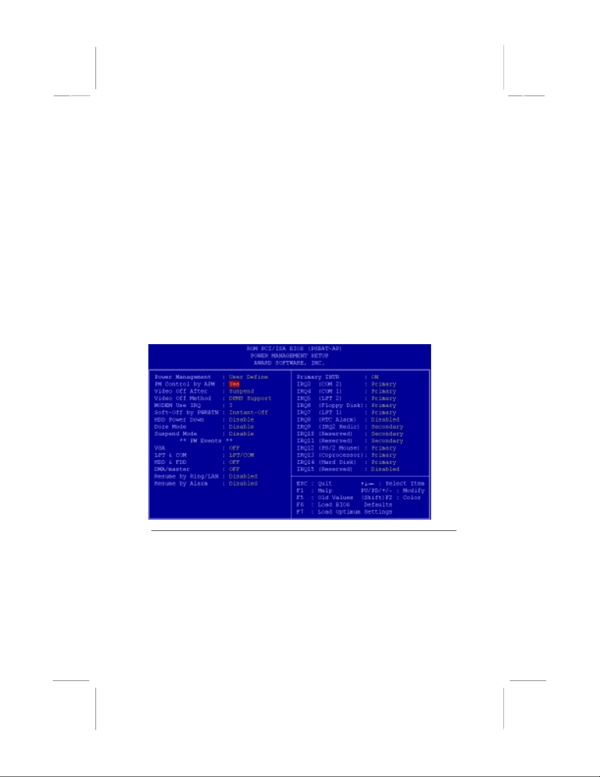
much of the routine power management. This mainboard supports ACPI
(advanced configuration and power interface).
This system supports three levels of power-saving modes; doze mode,
standby mode, and suspend mode. Standby mode uses less power than
doze mode and suspend mode uses the least power.
The power management in the setup utility lets you specify a timeout for
each of the power-saving modes, and a timeout for a hard disk drive
power down. A timeout, means a period of time when the system (or the
hard disk drive) is inactive. If the timeout completes, the system powersaving mode will execute, or the hard disk drive will power down.
You can resume from the power-saving modes by carrying out any of the
activities which are enabled in the list Reload Global Timer Events. If the
hard disk has been powered down it will automatically resume to full
power when an access to the hard disk is required (this takes just a few
seconds).
Power Management Default: User Define
This item acts like a master switch for the power-saving modes and hard disk
timeouts. If this item is set to Disabled, all the power-saving modes are disabled.
If this item is set to Max Saving, doze, standby, and suspend mode, will occur
after a timeout of 20 seconds. If this item is set to Min Saving, doze, standby,
and suspend mode will occur after a timeout of 40 minutes. If the item is set to
User Define, you can insert your own timeouts for the power-saving modes.
32
Page 36

PM Control by APM Default: Yes
Windows 95 and 98 have built-in power management capabilities called APM
(advanced power management). When you enable this item, you allow the APM
routines in Windows to operate on your system.
Video Off Option Default: Suspend -> Off
This option defines which level of power-saving mode is required in order to
power down the video display. As a default, the video powers down in suspend
mode but not standby mode.
Video Off Method Default: DPMS Support
This item defines how the video is powered down to save power. As a default,
this is set to DPMS Support (display power management software).
Modem Use IRQ Default: 3
If you would like an incoming call on a modem to automatically resume the
system from suspend mode, use this item to specify the interrupt request line
(IRQ) that is used by the modem.
Soft-Off by PWRBTN Default: Instant-Off
Under ACPI (advanced configuration and power interface) the system can be
turned off mechanically (by the power button) or it can undergo a software power
off. If the system has been turned off by software, the system can be resumed by
a LAN, MODEM or ALARM wake up signal. This item allows you to define a
software power off using the power button. If the value is set to Instant-Off, the
power button will automatically cause a software power off. If the value is set to
Delay 4 Sec. the power button must be held down for a full four seconds to
cause a software power off.
HDD Power Down Default: Disabled
You can use this item to set a timeout for a hard disk powerdown. You can set a
time from 1 to 15 minutes. If the hard disk is inactive for the time specified, it will
power down. It will automatically return to full power when it is next accessed.
Doze Mode Default: Disabled
If you have selected User Define for the Power Management item, you can set
this item to a selection of timeouts from 20 seconds to 40 minutes.
Suspend Mode Default: Disabled
If you have selected User Define for the Power Management item, you can set
this item to a selection of timeouts from 20 seconds to 40 minutes.
VGA Default: OFF
When this item is enabled, any activity on the graphics system can reset powersaving mode timeouts to zero, or resume the system from a power saving mode.
LPT & COM Default: LPT/COM
When this item is enabled, it defines system activities which can reset powersaving mode timeouts to zero, or resume the system from a power saving mode.
This item is for transmissions through the serial or parallel ports.
33
Page 37

HDD & FDD Default: ON
When this item is enabled, it defines system activities which can reset powersaving mode timeouts to zero, or resume the system from a power saving mode.
This item is for hard disk and/or diskette drive activity.
DMA/master Default: OFF
When this item is enabled, it defines system activities which can reset powersaving mode timeouts to zero, or resume the system from a power saving mode.
This item is activity through the system DMA controller.
Wake Up On LAN Default: Enabled
This item allows you to enable or disable the LAN wake up function that is a
feature of this mainboard. When enabled, traffic through a network will resume
the system from any of the power-saving modes.
Modem Ring Resume Default: Disabled
This item allows you to enable or disable the modem wakeup function that is a
feature of this mainboard. When enabled, traffic through a fax/modem will
resume the system from any of the power-saving modes.
RTC Alarm Resume Default: Disabled
This item lets you install a wakeup alarm, which resumes the system from a
power saving mode at a fixed date and time. When the item is enabled, new
items appear which allow you to set the date and time of the alarm.
Primary INTR Default: On
This item acts like a master switch for all the interrupt items that follow. If this
item is set to ON, the all the following interrupts can be manually configured to
act as resets for the power saving timeouts. If this item is set to OFF, then all the
following interrupt items cannot be used to reset the power saving timeouts.
IRQX
These interrupt events can act as triggers to reset the power saving timeouts or
other system maintenance tasks. If you set an interrupt event to Primary, any
activity on that interrupt will reset the timeouts that use the primary timer (e.g. the
power saving modes). If you set an interrupt to Secondary, then any activity on
the interrupt will reset those timeouts that use the secondary timer (usually
background maintenance tasks). If you set an interrupt event to Disabled, any
activity on the interrupt will not reset the timeouts.
PNP/PCI Configuration Option
This option displays a table of items that configures how PNP (Plug and
Play) and PCI expansion cards operate in your system.
34
Page 38

PNP OS Installed Default: No
If you have installed a Plug and Play operating system such as Windows 95 or
98, you can change this item to Yes. When the item is set to Yes you can use
the Device Manager utility in the operating system to make changes to the
configuration of expansion cards.
Resources Controlled By Default: Manual
You should leave this item at the default Manual. If you find that you cannot get a
particular expansion card to work properly, you might be able to solve the
problem by changing this item to Manual, and defining the characteristics of the
card in the new items which appear.
In the default Manual, the display will list a series of items that allow you to
define the assignments of the system interrupt lines (IRQs) and Direct Memory
Access (DMA) channels. As a default, these items are set to PCI/ISA PnP. If you
install an ISA-bus card that does not support PNP, and it requires a special IRQ
and DMA, you can modify the list of assignments. Change the values of the IRQ
and DMA that are required to Legacy ISA.
Reset Configuration Data Default: Disabled
If you enable this item and restart the system, any PNP configuration data stored
in the BIOS setup will be cleared from memory. New updated configuration data
will be created.
Assign IRQ for USB Default: Enabled
When this item is enabled, the system will assign an IRQ to the USB ports.
35
Page 39

Load BIOS Defaults Option
This option displays a dialog box which allows you to install BIOS
defaults for all appropriate items in the whole setup utility. Press the Y
key and then the Enter key to install the defaults. Press the N key and
then Enter to not install the defaults. The BIOS defaults do not place
great demands on the system and are generally very stable. If your
system is not running correctly, you might like to install the BIOS defaults
as a first step in getting your system working properly again. If you only
want to install BIOS defaults for a specific option, select and display the
option, and press the F6 key.
Load Setup Defaults Option
This option displays a dialog box which allows you install setup defaults
for all appropriate items in the whole setup utility. Press the Y key and
then the Enter key to install the defaults . Pr ess the N key and then Enter
to not install the defaults. The setup defaults can place some demands
on the system that are greater than the performance level of the
components, such as the processor and the memory. You could cause
fatal errors or recurring instability of you install the optimum defaults
when your hardware does not support it. If you only want to install
optimum settings defaults for a specific option, select and display that
option, and then press the F7 key.
Integrated Peripherals Option
This option displays a list of items which defines the operation of some
peripheral items on the system’s input/output ports.
36
Page 40
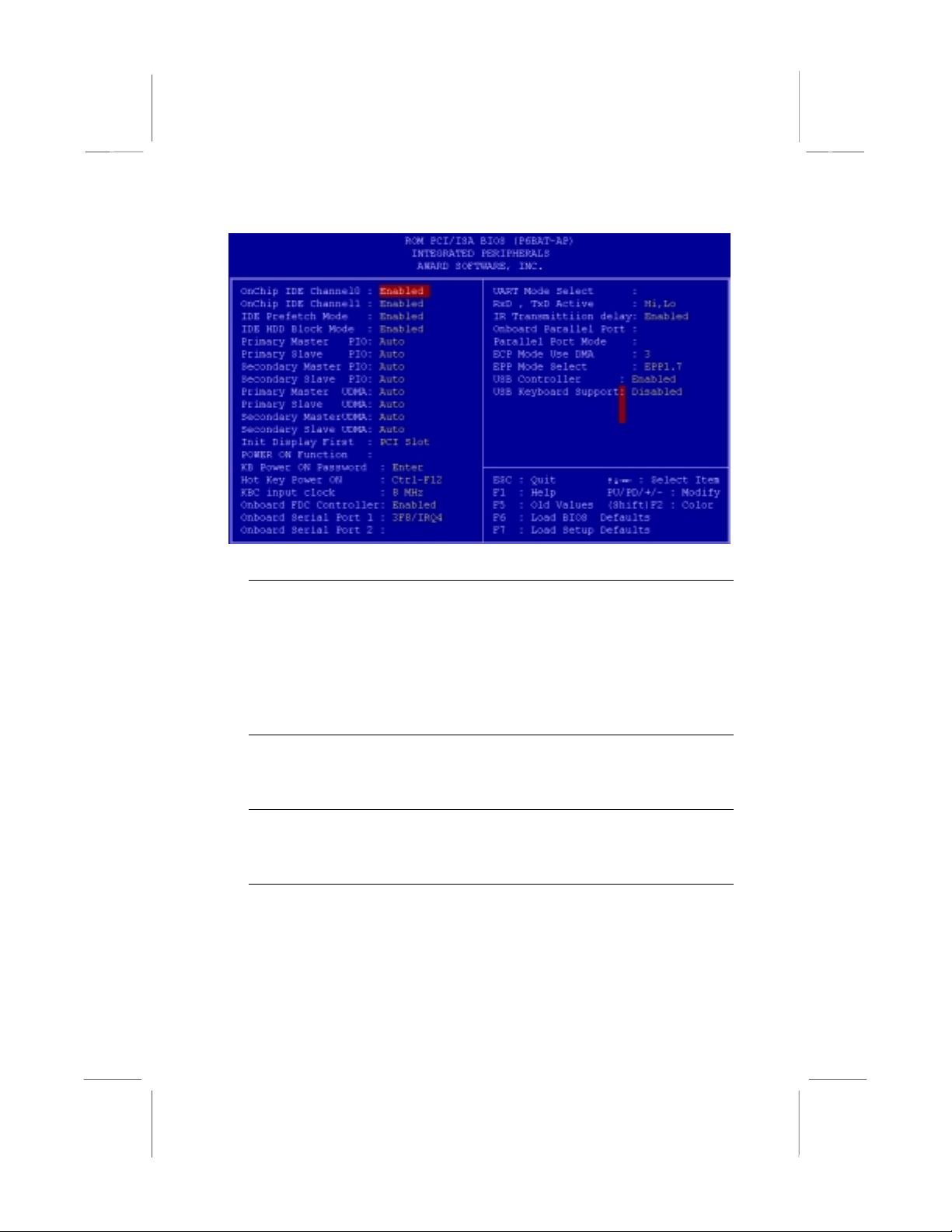
OnChip IDE Channel0 Default: Enabled
OnChip IDE Channel1 Default: Enabled
You can use these items to enable or disable the primary (0) and secondary (1)
IDE channels that are built into this mainboard. When one or both channels are
enabled, items appear which allow you to set the PIO (programmable
input/output) mode and the UltraDMA mode for master and slave devices on the
channels. We recommend that you leave these items at the default value Auto.
The system will then automatically use the best performance PIO mode and
UltraDMA mode for each device.
IDE Prefetch Mode Default: Enabled
The built-in IDE drive interfaces support IDE prefetching for faster drive accesses.
If you use an alternative IDE interface (on an expansion card), disable this field if
the alternate IDE interface does not support prefetching.
IDE HDD Block Mode Default: Enabled
IDE hard disks can deliver better performance if they use block mode transfer.
Most modern hard disk drives support block mode transfers so this item is
Enabled as a default.
IDE Primary Master PIO Default: Auto
IDE Primary Slave PIO Default: Auto
IDE Secondary Master PIO Default: Auto
IDE Secondary Slave PIO Default: Auto
Each IDE channel supports a master device and a slave device. These four
items let you assign which kind of PIO (Programmed Input/Output) is used by
IDE devices. You can choose Auto, to let the system auto detect which PIO
mode is best, or you can install a PIO mode from 0-4.
37
Page 41

IDE Primary Master UDMA Default: Auto
IDE Primary Slave UDMA Default: Auto
IDE Secondary Master UDMA Default: Auto
IDE Secondary Slave UDMA Default: Auto
Each IDE channel supports a master device and a slave device. This
motherboard supports UltraDMA. UltraDMA technology provides faster access to
IDE devices. If you install a device which supports UltraDMA, change the
appropriate item on this list to Auto. You may have to install the UltraDMA driver
supplied with this motherboard in order to use an UltraDMA device.
Init Display First Default: PCI Slot
Use this item to define if your graphics adapter is installed in one of the PCI slots,
or if you have installed an AGP graphics adapter into the AGP slot.
Power On Function Default: Hot KEY
KB Power ON Password Default: [Enter]
Hot Key Power ON Default: Ctrl-F12
The Power On Function item allows you to power on the system by pressing hotkeys, or typing in a password. If you choose Password, you can use the item KB
Power On Password to install a power on password. If you set this item to Hot
Key, you can then use the item Hot Key Power On to choose which hot keys are
installed.
KBC input clock Default: 8 MHz
This item lets you set a frequency for the input clock of the keyboard controller.
Leave this item at the default value 8 MHz.
Onboard FDC Controller Default: Enabled
This item enables or disables the floppy diskette drive controller built into this
mainboard.
Onboard Serial Port 1 Default: 3F8/IRQ4
This item lets you disable the built-in serial port 1, or enable it by assigning an
I/O address and an Interrupt Request Line (IRQ).
Onboard Serial Port 2 Default: 2F8/IRQ3
This item lets you disable the built-in serial port 2, or enable it by assigning an
I/O address and an Interrupt Request Line (IRQ).
UART Mode Select Default: Normal
This item defines the operation of serial port 2. I n the default Normal setting,
serial port 2 is assigned to the connector on the mainboard. If you have installed
an optional infrared port, you must change the setting of this item to either IrDA,
or ASKIR. These settings will disable the mainboard serial port connector and
assign serial port 2 to the infrared device. IrDA prepares the port to receive
infrared communications using the IrDA serial infrared standard. ASKIR prepares
the port to receive infrared communications using the ASK serial infrared
standard. The ASK standard is supported my many devices made by the Sharp
Corporation. If you have selected an IR mode, you can use the following two
items RxD, TxD Active, and IR transmission delay to set the parameters of the
38
Page 42

infrared port. See the documentation for the infrared port for information on these
items.
Onboard Parallel Port Default: 378/IRQ7
This item lets you disable the built-in parallel port, or enable it by assigning an
I/O address and an Interrupt Request Line (IRQ).
Parallel Port Mode Default: ECP + EPP
This item defines the operation of the parallel port. As a default it is set to ECP +
EPP. If you are connected to a parallel device that supports the higherperformance EPP (enhanced parallel port) or the ECP (extended capabilities port)
make the appropriate changes to this item. If you change the parallel port to EPP
or ECP, new items appear that let you configure the EPP and ECP modes.
OnChip USB Default: Enabled
This mainboard has a built-in USB (universal serial bus) port so you should leave
this item at the default value Enabled.
USB Keyboard Support Default: Disabled
If you connect a USB keyboard to your system, enable this item.
Supervisor Password and User Password
These two items can be used to install a Supervisor Password and a
User Password. If you log on as Supervisor, you have full access to the
system, and you can restrict the permissions granted to someone who
logs on as User. For example, a Supervisor can restrict a User from
entering the setup utility.
To install a Supervisor or User Password, follow these steps:
1. Highlight the item Supervisor/User password on the main menu and
press Enter.
2. The password dialog box will appear.
3. If you are installing a new password, carefully type in the password.
You cannot use more than 8 characters or numbers. The password
will differentiate between upper case and lower characters. Press
Enter after you have typed in the password. If you are deleti ng a
password that is already installed just press Enter when the
password dialog box appears.
4. The system will ask you to confirm the new password by asking you
to type it in a second time. Carefully type the password again and
press Enter, or just press Enter if you are delet ing a pass wor d that
is already installed.
5. If you typed the password correctly, the password will be installed.
39
Page 43

IDE HDD Auto Detection Option
This item automatically detects and installs any hard disk drives installed
on the primary and secondary IDE channel. Most modern drives can be
detected. If you are using a very old drive that can’t be detected, you can
install it manually using the Standard CMOS Setup option.
Setup will check for two devices on the primary IDE channel and then
two devices on the secondary IDE channel. At each device, the system
will flash an N in the dialog box. Pres s Enter to skip the device and
proceed to the next device. Press Y, then Enter to tell the system to
auto-detect the device.
Save And Exit Setup Option
Highlight this item and press Enter to save the changes that you have
made in the setup utility and exit the setup program. When the Save and
Exit dialog box appears, press Y to save and exit, or press N to return to
the setup main menu.
Exit Without Saving Option
Highlight this item and press Enter to discard any changes that you have
made in the setup utility and exit the setup program. When the Exit
Without Saving dialog box appears, press Y to discard changes and exit,
or press N to return to the setup main menu.
40
Page 44

CChhaapptteerr 44:: SSooffttwwaarre
e
About the Software
The software for this mainboard is supplied on a CD-ROM. The disk has
some folders that can be used by many different mainboards, for
example the UTILITY and PERIPHERAL folders. Some folders can only
be used by mainboards which have certain brands of chipsets, for
example the INTEL and VIA folders. In addition, software that is
specifically intended for one kind of mainboard is stored in a folder with
the name of that board. The folder for this mainboard is stored in the
MS7102C folder.
Note: Never try to install software from a folder that is not
specified for use with your mainboard.
Folders for this Mainboard
For this board, you can install software from the following folders:
Utility Folder
You can use the software in the following sub-folders:
! AWDFLASH: Software to erase and install new revisions of the
syst em BIOS
! DIRECTX5: Software display drivers for Microsoft’s DirectX Rev. 5
specification
! PC-CILLIN: Anti-virus software
! BITWARE: Software for the built-in fax/modem
! GAMUT: Audio rack for built-in sound system
CMI8X38 Folder
You can use the software from the following sub-folders:
! AUDIO: Drivers and software for the built-in audio system
! MODEM: Drivers and software for the built-in fax/modem
41
Page 45

Peripheral Folder
You can use the software in the following sub-folders:
! KEYBOARD, CD-ROM, MOUSE: These three folders have drivers
for accessories manufactured by BTC. Some system assemblers
ship these accessories with complete systems based on this
mainboard.
VIA Folder
The setup program supports to register VIA chipset’s function in
Windows 95/98.
! IDE : IDE Bus master drivers for WIN95/98/NT
! IRQ: This driver is for Windows 95/98. This driver solves some
issues regarding the IRQ assignment of PCI Devices.
! Registry: This driver can register VIA chipset’s function.
! USB_UPDATE: This driver updates Windows 95 to support USB.
! VxD: The VxD driver provides support for an AGP graphics adapter.
MS7102C Folder
You can use the software in the following sub-folders:
! AUDIO, MODEM: These folders are empty. A readme file directs
you to alternate location with the required software.
! MONITOR : Hardware monitoring software for Windows 95/98, and
Windows NT4.0/5.0
Note: Some folders are subdivided into different operating
systems such as DOS, Windows 95, Windows NT, and so on.
Always make sure that you are installing the correct software for
the operating system on your comp uter. Some folders are also
subdivided into different language versions, such as English,
French, German and so on.
Note: Before installing any software, always inspect the folder for
files named README.TXT, INSTALL.TXT, or something similar.
These files may contain important information that is not included
in this manual.
42
Page 46

Running the Support CD-ROM
1. Place the disk in your CD-ROM drive. If you are running Windows
with Autoplay enabled, the opening screen of the CD appears
automatically. Click on READ ME to read the latest instructions.
2. Click on the item BROWSE THE CD TITLE. This uses Windows
Explorer to show the contents of the support CD.
3. Double click on a folder to display the sub-folders.
4. Before installing the software, look for a file named README.TXT,
or something similar. This file may contain important information to
help you install the software correc t l y.
5. Some software is installed in separate folders for different operating
systems, such as DOS, WIN NT, WIN95/98, and so on. Always log
on to the correct folder for the kind of OS you are using.
6. To install the software, you usually execute a file named
SETUP.EXE or INSTALL.EXE by double clicking on the filename.
Utility Folder Installation Notes
Award Flash Memory Utility
This utility lets you erase the system BIOS stored on a Flash Memory
chip on the mainboard, and lets you copy an updated BIOS to the chip.
Take care how you use this program. If you erase the current BIOS and
fail to write a new BIOS, or write a new BIOS that is incorrec t, your
system will malfunction.
There are two flash memory utilities called AWD66.EXE and
AWD712.EXE. For this mainboard you must use the AWD66.EXE utility.
To use the utility, you must be in real-mode DOS (not the DOS box that
is available in Windows 95/98/NT). If you are using WINDOWS 95/98,
shut down your computer and select the option Restart in DOS in the
shut-down dialog box. If you are running Windows NT, shut down your
computer and boot from a DOS diskette temporarily in order to run the
flash memory utility.
DirectX5 Drivers
The DirectX drivers are for installation only in Windows 95/98. The
directX drivers need to be installed before you install an AGP driver. You
may be able to get more up-to-date directX drivers from the Microsoft
web site. Start the installation by clicking on the file DX5CORE.EXE.
43
Page 47

PC-Cillin Anti-Virus Utility
Anti-virus software is provided for DOS, for WIN95, and WIN 98. Log on
to the appropriate directory for your operating system. For DOS, copy all
the files in the DOS folder to your hard disk drive. For Windows 95, log
on to the Disk 1 folder and run SETUP. For Windows 98, run SETUP.
CMI8X38 Folder Installation Notes
Audio Software
This folder has software and drivers for the sound system that is
integrated on this mainboard. Drivers are provided for Windows 95/98,
Windows NT, and DOS. An MS-WORD format manual is stored in the
MANUAL folder.
DOS Installation
Log on to the DOSDRV folder and run the program INSTALL.EXE
Windows 95/98 Installation
Please specify the path to the CD-ROM\CMI8X3 8\AUDIO\W95-98\DRV
when your system detects the installed audio system. To install the audio
applications, log on to the W95-98 folder, and then log on to the APPS
folder. Run the SETUP program.
Windows NT 4.0 Installation
1. Press the "Start" button.
2. Move the highlight to "Settings" and select "Control Panel".
3. Double click on the "Multimedia" icon.
4. Select the "Devices" tab.
5. Press the "Add..." button.
6. Select item "Unlisted or Updated Driver" in the "List of Drivers" list
box.
7. Specify the path to the PCI audio NT drivers.
8. Select "C-Media CM8738 PCI Device" and press the "OK" button.
9. Choose proper I/O or the "OK" button for the default setting.
10. Restart the Windows NT system.
To install the audio applications, log on to the NT4 folder, and then log
on to the APPS folder. Run the SETUP program.
44
Page 48

Modem Driver and Software
1. In the BIOS system setup utility
2. In the “Chipset Features Setup” of the system setup utility
3. Enable the item “On Board Modem”
Install the Modem driver from the sub-folders for Windows 95/98 or
Windows NT4.0.
Windows 95/98
The modem is a plug and play device so Windows 95/98 will
automatically detect the presence of your modem. When the Plug and
Play wizard begins to look for modem drivers, click on the button that
says Have Disk and then browse or type in the pathname to the
CMI8x58\modem\win9x folder.
Windows NT 4.0
Follow the instructions in the README file in the WINNT4 sub-folder.
VIA Folder Installation Notes
The setup program supports to register VIA chipset’s function in
Windows 95 and Windows 98.
Installation procedure:
1. Run setup and select “ install VIA Chipset Functions ‘Registry’”,
then it will automatically install this program.
2. You can see that it displays “VIA Power Management Controller”
and “VIA PCI to USB Universal Host Controller”
Note: If user want to upgrade Windows 95 to Windows 95 OSR
2.1(4.00.950 B), it’s necessary to remove USB from other device.
IDE Bus Master Driver
The IDE Bus Master Drivers are stored in a folder named IDE.
Windows 95/98 Installation
1. Click the Windows Start button, and then click on Run.
2. Browse to the folder IDE and select the program called SETUP.EXE.
3. Click on the Install button on the setup screen.
4. Follow the instructions on the screen to complete the installation of
the Bus Mastering IDE drivers.
45
Page 49

Windows NT Installation
1. Carry out the installation instructions for Windows 95/98 steps 1 to 4.
2. In the Control Panel, select the icon SCSI adapters.
3. Select the Add button on the drivers sheet.
4. Select the item “VIA Bus Master PCI IDE Dr iver” and click OK.
5. Reboot the system.
Installing the IRQ Routing Driver
This driver is for Windows 95/98. This driver solves some issues regardin g the
IRQ assignment of PCI devices.
Windows 95 Installation
1. Click the Windows Start button, and then click on Run.
2. Browse to the correct folder and select the program called
SETUP.EXE.
3. Follow the instructions on the screen to complete the installation.
Windows 98 Installation
1. In the Integrated Peripherals page of the system setup utility, enable
the item OnChip USB.
2. In the PNP/PCI Configuration page of the system setup utility,
enable the item Assign IRQ for USB.
3. Restart the system and continue with steps 1, 2, and 3 of the
Windows 95 installation instructions.
VxD Drivers
The VxD driver provides support for an AGP graphics adapter. You only
need to install this driver if you are running Windows 95, and you have
installed the mainboard with an AGP graphics adapter. The VIA VxD
driver is for use in Windows 95 version OSR 2.1 (4.00.950 B) or later.
Windows 95 Installation
You need the following files installed on your system before beginning
the installation:
1. Get the file "USBSUPP.EXE" from Microsoft, which includes the
USB supplement and a new memory manager (VMM32.VxD)
needed for the AGP DIME (Direct Memory Execute) feature.
2. Get DirectX 5.0 from Microsoft. DirectX 5.0 is the first DirectX
version that supports AGP's DIME.
46
Page 50

3. Get AGP Master (i.e., AGP VGA) Driver from the vendor of your
AGP graphics adapter.
4. Get "VIAG ART .VX D", a vir tu al device manager which usually will be
installed in the following installation procedure of the Windows 95
card driver.
Installation Instructions
1. Click the Windows Start button, and then click on Run.
2. Browse to the correct folder and select the program called
SETUP.EXE.
Follow the instructions on the screen to complete the installation.
Mainboard (MS7102C) Installation Notes
Most of the sub-folders in this folder are empty, with a short README
file giving directions to alternate folders for the appropriate software. Two
folders contain software that you can install.
Monitor Sub-folder
The software in this folder provides a graphical interface to the hardware
monitoring feature of this mainboard. The software will run under
Windows 95/98 or Windows NT4.0. Follow the installation instructions
contained in the file INSTALL.TXT.
47
Page 51
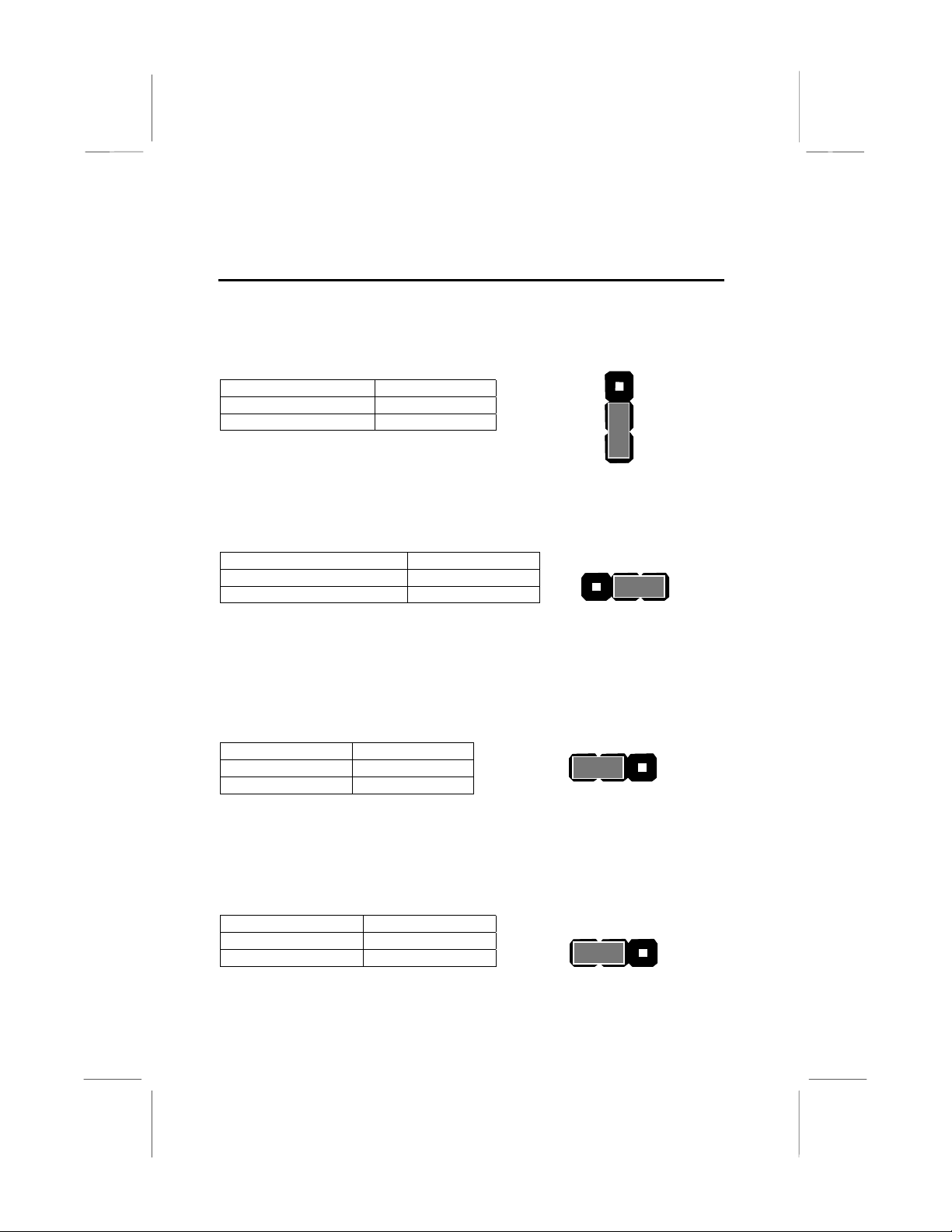
Appendix 1: Quick Jumper Setting Reference
JP1: Clear CMOS Memory Jumper
Use this 3-pin jumper to clear the contents of the CMOS memory.
Function Jumper Cap
Normal Operation Short pins 1-2
Clear CMOS Short pins 2-3
JP1
3
2
1
JP2: Keyboard Power On Jumper
Use this 3-pin jumper to enable a keyboard power on.
Function Jumper Cap
Disable keyboard power on Short pins 1-2
Enable keyboard power on Short pins 2-3
1 2 3
JP2
JP4: System Bus Frequency Select Jumper
Use this jumper to select an auto-detected system bus frequency or
force a frequency of 100 MHz
JP4
Function Jumper Cap
Normal Short pins 1-2
Force 100 MHz Short pins 2-3
1 2 3
JP7: Flash BIOS Enable/Disable Jumper
Use this 3-pin jumper to enable or disable a flash BIOS.
Function Jumper Cap
Enable flash BIOS Short pins 1-2
Disable flash BIOS Open pins 2-3
1 2 3
48
JP7
Page 52

PANEL: Case Switches and Indicators
Use the Panel connector to implement the switches and indicators on the
system case.
PANEL
23
Function Pins
Power Indicator 1+, 2+, 3
Sleep Switch 4, 5
Green Indicator 7+, 8+, 9
Keylock 10, 11
Reset Switch 12, 13
Speaker 15+, 16, 17, 18
Hard Disk Indicator 20+, 21
Power Switch 22+, 23
Power SW 22-23
HDD LED 20-21
Speaker 15-16-17-18
Reset SW 12-13
KeyLock 10,11
Green LED 7-8-9
Sleep SW 4-5
Power LED 1-2-3
1
49
 Loading...