

Page 1

Important Information
Copyright
This publication, including all photographs, illustrations and software, is protected
under international copyright laws, with all rights reserved. Neither this manual, nor
any of the material contained herein, may be reproduced without the express written
consent of the manufacturer.
Disclaimer
The information in this document is subject to change without notice. The
manufacturer makes no representations or warranties with respect to the contents
hereof and specifically disclaims any implied warranties of merchantability or fitness
for any particular purpose. Further, the manufacturer reserves the right to revise this
publication and to make changes from time to time in the content hereof without
obligation of the manufacturer to notify any person of such revision or changes.
Trademark Recognition
Microsoft, MS-DOS and Windows are registered trademarks of Microsoft Corp.
MMX, Pentium, Pentium-II, Celeron are a registered trademarks of Intel Corporation.
VGA, OS/2, PS/2 are registered trademarks of International Business Machines.
AMD, K5, K6 are registered trademarks of Advanced Micro Devices Inc.
Cyrix, M1 are registered trademarks of Cyrix Corporation.
Other product names used in this manual are the properties of their respective owners
and are acknowledged.
Version 1.0
Page 2

Safety Compliance
Federal Communications Commission (FCC)
This equipment has been tested and found to comply with the limits for a Class B
digital device, pursuant to Part 15 of the FCC Rules. These limits are designed to
provide reasonable protection against harmful interference in a residential installation.
This equipment generates, uses, and can radiate radio frequency energy and, if not
installed and used in accordance with the instructions, may cause harmful interference
to radio communications. However there is no guarantee that interference will not
occur in a particular installation. If this equipment does cause harmful interference to
radio or television reception, which can be determined by turning the equipment off
and on, the user is encouraged to try to correct the interference by one or more of the
following measures:
♦ Reorient or relocate the receiving antenna.
♦ Increase the separation between the equipment and the receiver.
♦ Connect the equipment onto an outlet on a circuit different from that to which
the receiver is connected.
♦ Consult the dealer or an experienced radio/TV technician for help.
Shielded interconnect cables and shielded AC power cable must be employed with this
equipment to insure compliance with the pertinent RF emission limits governing this
device. Changes or modifications not expressly approved by the system’s
manufacturer could void the user’s authority to operate the equipment.
Declaration of Conformity
This device complies with part 15 of the FCC rules. Operation is subject to the
following conditions:
♦ This device may not cause harmful interference, and
♦ This device must accept any interference received, including interference that
may cause undesired operation.
Canadian Department of Communications
This class B digital apparatus meets all requirements of the Canadian Interferencecausing Equipment Regulations.
Cet appareil numérique de la classe B respecte toutes les exigences du Réglement sur
le matériel brouilieur du Canada.
Page 3

TTaabbllee ooff CCoonntteenntts
s
Chapter 1: Introduction
Welcome.... .................. .................. ........ ......... ........ 1
About the Manual ........... .................. ........ ......... ........ 1
Checklist .... .................. .................. ........ ......... ........ 2
Features..... .................. .................. ........ ......... ........ 2
Chapter 2: Installation
Before You Begin........... .................. ........ ......... ........ 5
Mainboard Guide............ .................. ........ ......... ........ 6
Preparing the Mainboard .................. ........ ......... ........ 7
Install the Mainboard in the System Case.... ......... ........ 12
Chapter 3: Setup
About the Setup Utility .... .................. ........ ......... ........ 17
Standard CMOS Setup Option ........... ........ ......... ........ 19
BIOS Feature Setup Option ............... ........ ......... ........ 20
Chipset Features Option. .................. ........ ......... ........ 22
Power Management Setup Option ...... ........ ......... ........ 24
PNP/PCI Configuration Option ........... ........ ......... ........ 27
Load BIOS Defaults Option ................ ........ ......... ........ 28
Load Optimum Settings Option........... ........ ......... ........ 28
Integrated Peripherals Option............. ........ ......... ........ 28
Password Settings ......... .................. ........ ......... ........ 31
IDE HDD Auto Detection Option ......... ........ ......... ........ 31
Save and Exit Setup Option ............... ........ ......... ........ 31
Exit Without Saving Option................ ........ ......... ........ 31
Chapter 4: Software
About the Software ......... .................. ........ .........32
Utility Folder Installation Guide........... ........ ......... ........ 32
Utility Installation Notes .. .................. ........ ......... ........ 33
Mainboard Folder Installation Guide ... ........ ......... ........ 34
Mainboard Installation Notes.............. ........ ......... ........ 34
CMI8338 Audio Folder Installation Guide..... ......... ........ 35
Appendix
1. Quick Jumper Setting Reference .... ........ ......... ........ 37
Page 4

1
CChhaapptteerr 11:: IInnttrroodduuccttiioon
n
Welcome
Congratulations on your purchase of the MS-7090S mainboard. The MS-7090S
mainboard is a micro-ATX board measuring 243.8 mm by 200 mm and using a 4-layer
printed circuit board. This board features a PGA370 ZIF (Zero Insertion Force)
processor socket. This socket can be installed with the latest generation of Intel
Celeron processors that are packaged in a Plastic Pin Grid Array (PPGA), just like the
original Pentium processors. The mainboard supports a system bus of 66 MHz that
permits the use of inexpensive 66 MHz memory chips. Three DIMM sockets are
provided for a maximum memory capacity of 256 MB. The mainboard has an
integrated 3D-sound system, and the Intel chipset supports an AGP graphics card.
Three PCI slots and one ISA slot are provided for system expansion.
This chapter contains the following information:
l About the Manual explains how the information in this manual is
organized
l Checklist comprises a list of the standard and optional components that are
shipped with this mainboard,
l Features highlights the functions and components that make this one of
the best value mainboards on the market
About the Manual
The manual consists of the following chapters:
Introduction
Use the Introduction Chapter to learn about the features of the mainboard, and the
checklist of items that are shipped with the package.
Installation
Use the Installation Chapter to learn how to install the mainboard and get your system
up and running.
Setup
Use the Setup Chapter to configure the mainboard for optimum performance.
Page 5

2
Software
Use the Software Chapter to learn how to use the software drivers and support
programs that are provided with this mainboard.
Checklist
Compare the contents of your mainboard package with the standard checklist below. If
any item is missing or appears damaged, please contact the vendor of your mainboard
package.
Standard Items
ü
1 x MS-7090S Mainboard
ü
1 x Cable/Bracket Pack
Diskette drive ribbon cable
IDE drive ribbon cable
ü
This User’s Manual
ü
Software Support CD-ROM Disc
Features
This is an economic platform which provides entry-level through to business-class
Pentium-II performance for minimum cost. This is a powerful platform that leverages
the low-cost/high-performance features of the new generation of Celeron processors.
Low-cost/high performance Processing
Intel’s new generation of Celeron processors are shipped in the familiar PPGA square
plastic package that are common to all Pentium and Pentium-compatible processors.
The mainboard has a PGA370 ZIF socket for the installation of the Celeron. (Note that
the socket has a different pinout than Pentium/Pentium compatibles and cannot be
used by Socket-7 processors.) The Celeron processor features Pentium-II performance
with internal clock speeds of 300, 333, 366, 400, and 433 MHz (higher speeds may be
forthcoming), 32K of level-1 cache memory, and 128K of level-2 cache memory. The
Celeron is an economic processor because it runs on a 66 MHz system bus so that the
mainboard design and components are not high-cost items. This mainboard allows
entry-level and business-class users to move up to Pentium-II performance at
minimum cost. Configuration for different processor speeds is automatically set by
firmware and motherboard switch or jumper settings are not required.
Inexpensive Memory
The board has three DIMM sockets for the installation of 168-pin, 3.3V non-buffered
DIMM memory modules. The DIMM memory modules can be installed with EDO or
SDRAM memory chips. The board supports a memory bus of 66 MHz, so inexpensive
66 MHz memory chips can be used. Each installed memory module can be populated
Page 6

3
with 16 MB up to 128 MB of memory, and can be single-sided or double sided.
However, total installed memory must not exceed 256 MB. If you install a doublesided module in either DIMM 2 or DIMM 3, you cannot install any memory module in
the other socket. DIMM1 is independent and does not have this limitation.
Highly Integrated Design
This mainboard features a high level of integrated functions provided by the onboard
chipsets. The Intel 82443EX provides all the north bridge support – CPU and memory
addressing, PCI-IDE controller, and PCI-bus interface. In addition, the 82443EX
provides a complete AGP graphics controller solution. The Intel 82371EB provides
the south bridge support – ACPI power management, real-time clock, and USB
interface. The Winbond W83977EF is a single chip I/O solution, and the Elite PCI
Audio-CMI8338 provides the onboard 3D audio feature. Hardware monitoring is
supported by the GL520SM. This highly integrated mainboard ensures stability and
allows a fully functional system to be created by adding just a processor, a graphics
adapter and memory.
Built-in PCI 3D Sound
The Elite PCI Audio-CMI8338 is a single chip solution for PCI-bus 3D audio. The
chip provides Sound Blaster 16-bit-compatible audio, plus support for Microsoft’s
DirectSound 3D specification and Aureal A3D interface. The sound ports include
jacks for speakers, microphone and stereo in, and a game/MIDI port. The audio system
supports full duplex operation and drivers are available for WIN 95/98 and WIN NT
4.0. The audio system can output sound to 4 speakers and also supports SPDIF 24-bit
digital sound input and output.
Solid Expansion Options
Because this is a highly integrated board with built-in audio and a full set of I/O ports,
it does not require a full set of expansion slots. The board provides three usable slots.
The board has three 32-bit PCI slots and one 8/16-bit ISA slot. The ISA slot is shared
with one of the PCI slots meaning that you can use either the ISA slot or the PCI slot,
but not both at the same time. PCI1 and PCI3 share a request line. This means that
only one of these slots can support a bus-mastering PCI expansion card.
Integrated I/O
Using the Winbond W83977EF I/O chip and the Intel 82443EX/82371EB chipset, the
board has a comprehensive set of integrated I/O ports. The I/O port array features PS/2
keyboard and mouse ports, a parallel port, two USB ports, two serial ports, a
game/MIDI port, and three audio jacks. Optionally, you can use the built-in mainboard
header to add in an infrared port. The mainboard has two PCI-IDE channels and a
floppy disk drive interface.
Page 7

4
Hardware Monitoring
This mainboard features hardware monitoring supported by the GL520SM system
monitor chip. Using the system BIOS, system administrators can track critical
hardware parameters such as CPU temperature and cooling fan speeds. Limits can be
set to ensure system power management prevents threshold temperatures and
parameters from being exceeded.
Keyboard Power On Feature
Using the system BIOS setup program, you can configure the system to turn on using
keyboard hot keys and mouse, or a keyboard typed password. A green keyboard is not
required.
Programmable Firmware
The mainboard includes Award BIOS which allows BIOS setting of CPU parameters.
The fully programmable firmware enhances the system features and allows users to set
power management, CPU and memory timing, LAN and modem wake-up alarms, and
so on. The firmware can also be used to set parameters for different Celeron processor
clock speeds so that you don’t need to change mainboard jumpers and switches.
Page 8

5
CChhaapptteerr 22:: IInnssttaallllaattiioon
n
Before You Begin
Before you begin to install your MS-7090S mainboard, take some precautions to
ensure that you avoid the possibility of damage to the product from static electricity.
Ensure too that you are installing the mainboard into a suitable case.
Static Electricity
In adverse conditions, static electricity can accumulate and discharge through the
integrated circuits and silicon chips on this product. These circuits and chips are
sensitive and can be permanently damaged by static discharge.
♦ If possible wear a grounding wrist strap clipped to a safely grounded device
during the installation.
♦ If you don ’t have a wrist strap, discharge any static by touching the metal case
of a safely grounded device before beginning the installation.
♦ Leave all components inside their static-proof bags until they are required for
the installation procedure.
♦ Handle all circuit boards and electronic components carefully. Hold boards by
the edges only. Do not flex or stress circuit boards.
Choosing a Case
The MS-7090S mainboard complies with the specifications for a micro-ATX board.
The micro-ATX format features small size, fewer expansion slots and smaller power
consumption, so that the system case is less expensive. You can also install this kind
of board into a full-size ATX case.
Some features on the mainboard are implemented by cabling connectors on the
mainboard to indicators and switches on the system case. Ensure that your case
supports all the features required. The MS-7090S mainboard can support one or two
floppy diskette drives and four enhanced IDE drives. Ensure that your case has
sufficient power and space for all the drives that you intend to install.
The mainboard has a set of I/O ports on the rear edge. Ensure that your case has an I/O
template that supports the I/O ports and expansion slots.
Page 9
6
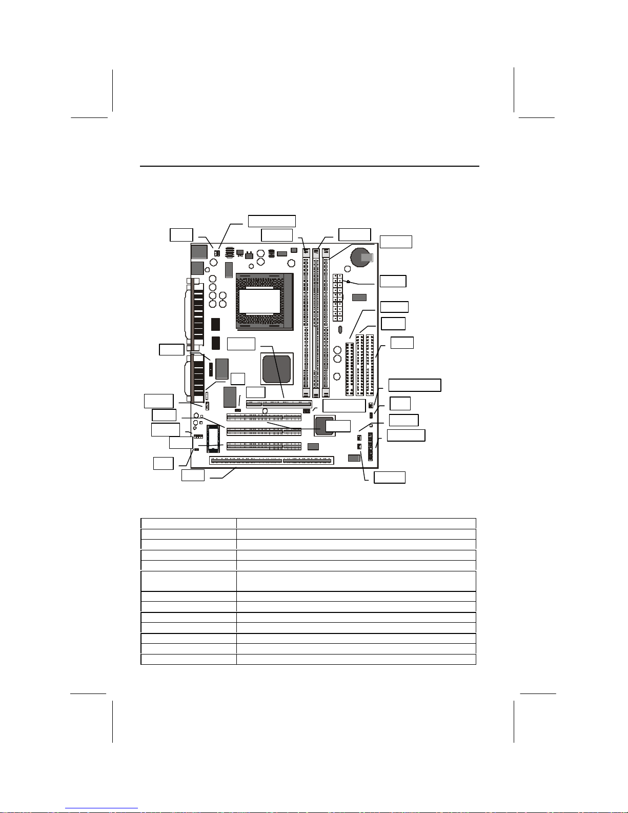
Mainboard Guide
Use the following illustration and key to identify the components on your mainboard.
1 11
1
AGP1
CD-IN
CPU FAN1
DIMM1
DIMM3
ATX1
SB LINK1
JP1
FDD1
IDE2
IDE1
CASE FAN1
PANEL1
WOM1
WOL1
PCI3
PCI2
J2
JP5
SIR1
SPDIF
SOCKET
PGA 370
DIMM2
PCI1
JP4
JP2
Key to Mainboard Components
Component Description
ISA1 1 x 8/16-bit ISA expansion slots
PCI 1,2,3 3 x 32-bit PCI expansion slots
AGP1 Slot for AGP graphics adapter
SOCKET PGA 370 Processor socket for Celeron processor
DIMM1, DIMM2,
DIMM3
Slots for 168-pin memory modules
FDD1 Connector for floppy disk drives
IDE1, IDE2 Primary and secondary IDE channels
ATX1 Connector for ATX power supply
SIR1 Connector for optional infrared port
PANEL1 Panel connector for switches and indicators
CPU FAN1 Power connector for CPU cooling fan
CASE FAN1 Power connector for case cooling fan
Page 10
7
WOM1 Connector for modem wake up
WOL1 Connector for LAN wake up
SPDIF SPDIF In/out connector (professional 24-bit digital audio
interface)
SB LINK1 SB-Link connector for optional PCI Sound Blaster audio
card
CD-IN Audio connector for optional CD-ROM drive
JP1 Clear CMOS memory jumper
JP2 Keyboard power on jumper
JP4 Audio enable/disable jumper
JP5 Set SPDIF output signal level jumper
J2 Auxiliary audio connector for optional CD-ROM drive
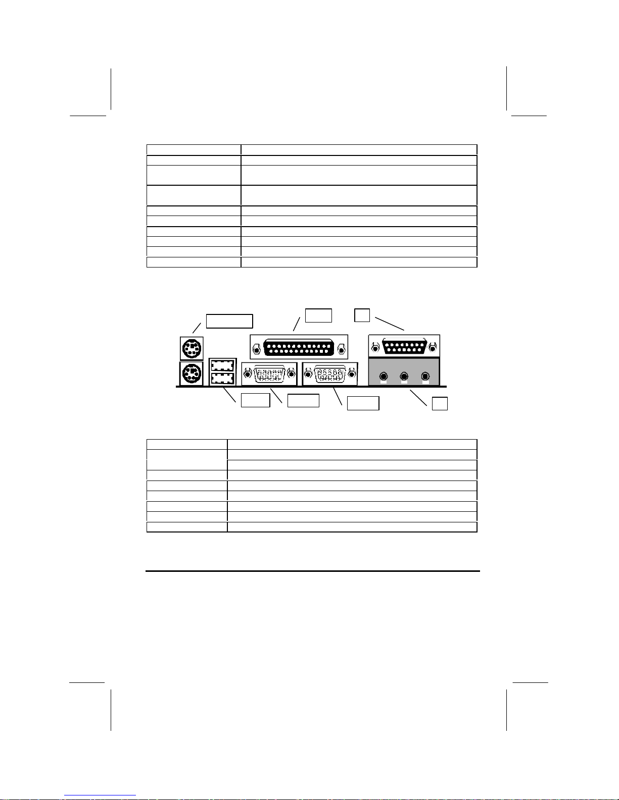
Side View of the Input/Output Ports
PS2KBM1
USB1
COM1
COM2
LPT1
J3
J3
Component Description
PS/2 port for pointing device (upper port)PS2KBM1
PS/2 port for keyboard (lower port)
LPT1 External parallel port
J3 (Upper) External game/MIDI port
J3 (Lower) Audio jacks for (from left to right) line out, line in, microphone
COM2 External serial port 2/4
COM1 External serial port 1/3
USB1 Two stacked Universal Serial Bus ports
Preparing the Mainboard
Prepare the main board by installing the Celeron Pentium-II processor and then
installing either 1, 2 or 3 memory modules. This board supports the new generation
Celeron processor that is packaged in a Plastic Pin Grid Array (PPGA) designed to fit
the PGA370 ZIF socket on the mainboard. You can use a Celeron that runs at either
300, 333, 366, 400 or 433 MHz. Next, install one or more memory modules. Finally,
review all the important jumper settings to ensure that the board is configured
correctly.
Page 11
8
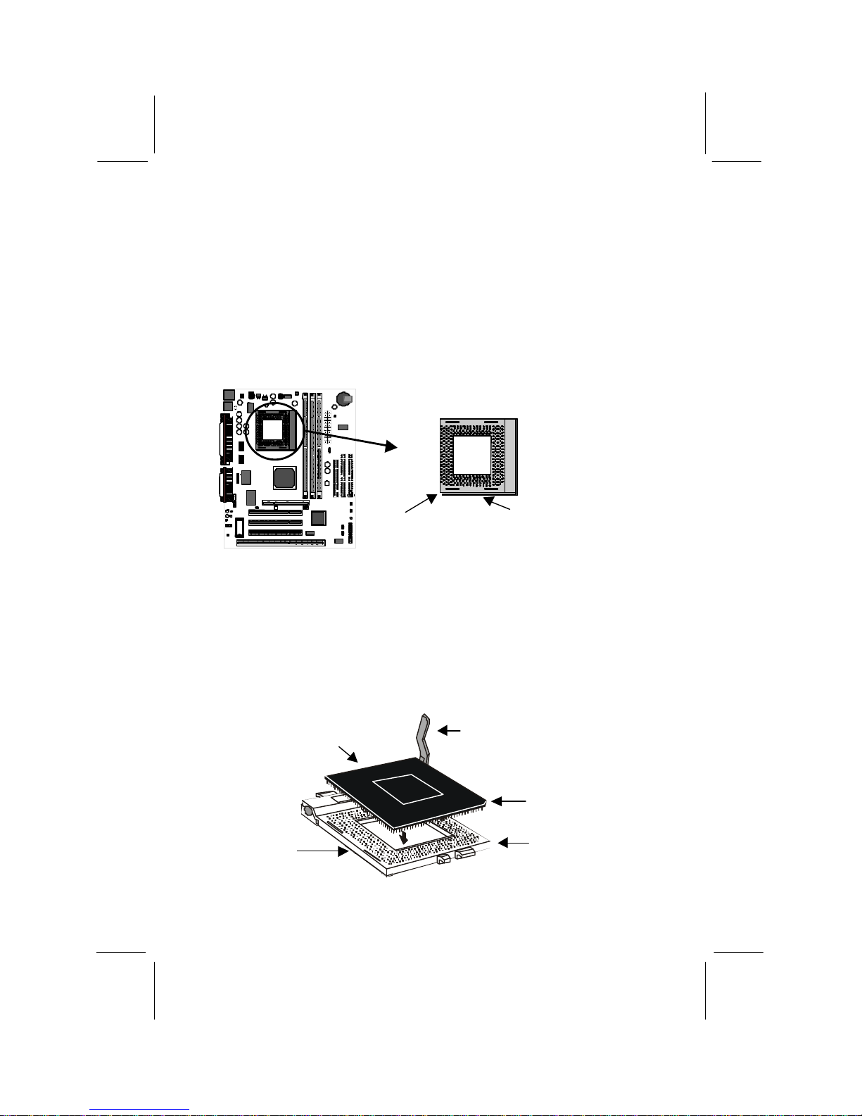
Install the Processor
This mainboard is installed with a PGA370 ZIF processor socket. This socket will
only support the PPGA Celeron processor. Do not try to insert a socket-7 processor
such as a Pentium or Pentium-compatible processor. The Celeron processors all run
over a 66 MHz system bus and have internal clock speeds ranging from 300 to 400
MHz. Configuration of the processor is made automatically using the mainboard BIOS
(see the Setup chapter).
Follow the steps below to install the Celeron processor in the PGA370 socket.
1. Locate the zero insertion force (ZIF) PGA370 socket for the processor.
2. On the socket and on the processor, identify the pin 1 corner. You can identify the
pin 1 corner by noting that in the rectangular matrix of holes on the socket, one
hole is absent on two corners. The front corner with the absent hole is the pin-1
corner. On the processor, the pin-1 corner is beveled. (see the illustration below).
3. Push the socket locking lever away from the socket to unhook it. Swing the lever
into the upright position.
4. Insert the processor into the socket taking care that you have matched the pin 1
corners. No force is required, and the processor should seat smoothly into the
socket.
Processor
Pin-1 Corner
Pin-1 Corner
Locking Lever
Socket
PGA370
Locking lever
Pin-1 corner
Typical Socket-PGA370
Page 12
9
5. Swing the locking lever down and hook it under the latch on the side of the socket
to lock it in place.
6. Locate the power connector for the processor cooling fan CPU FAN1. If your
processor has a cooling fan installed, connect the cable from the cooling fan to
CPU FAN1.
Install the Memory Modules
For this mainboard, you must use 168-pin 3.3V non-buffered Dual In-line Memory
Modules (DIMMs). The memory chips can be EDO RAM or SDRAM. The memory
bus runs at 66 MHz so you need not use PC-100 memory modules. You can use
memory modules that have a capacity of 16 MB up to 128 MB. Total installed
memory must not exceed 256 MB.
You can use memory modules which have memory chips on just one side (singlesided) or memory chips on both sides (double-sided). If you install a double-sided
module in either DIMM 2 or 3, you must leave the other socket empty. DIMM1 is
independent and does not have this limitation.
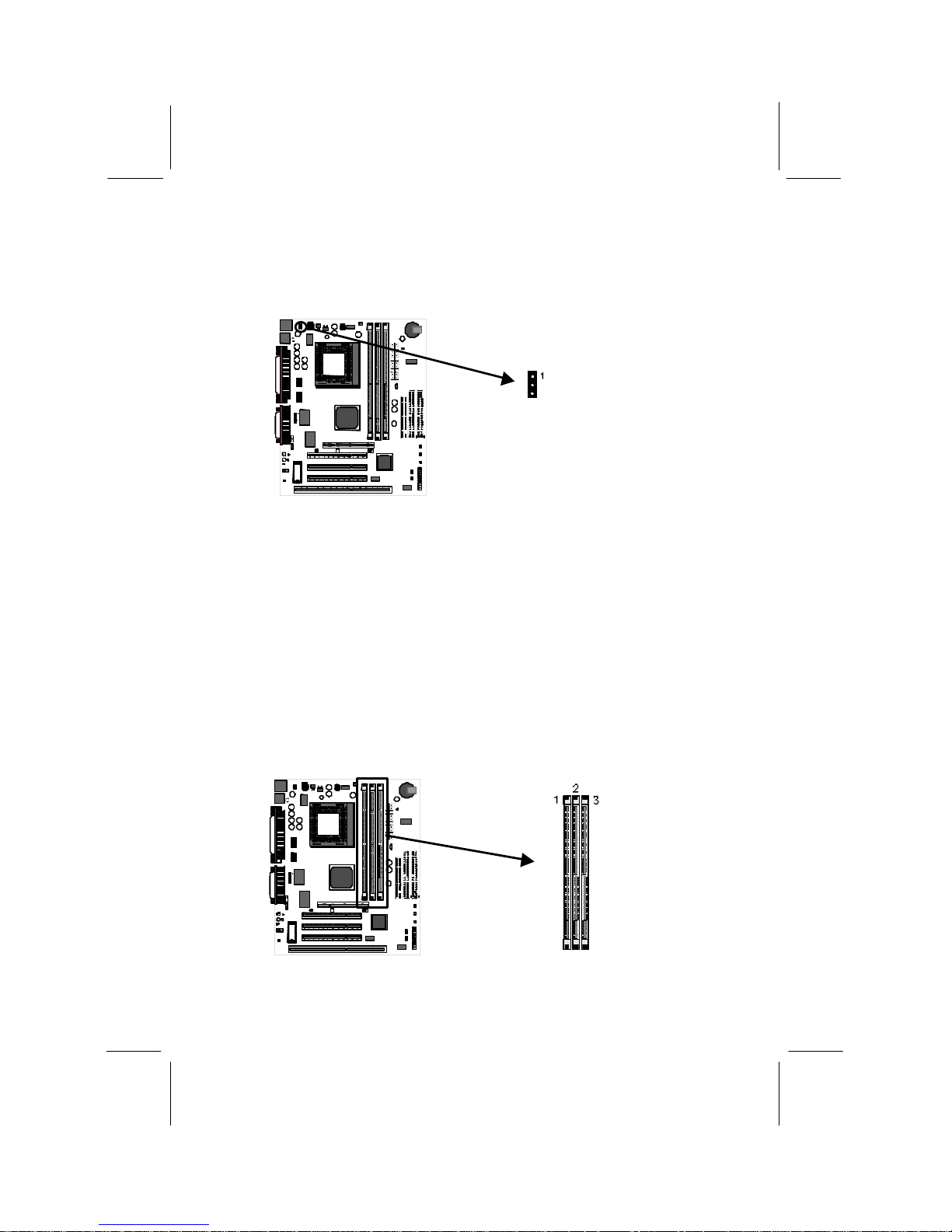
1. Locate the DIMM sockets on the mainboard.
CPU FAN1
DIMM Sockets
Page 13

10
2. The DIMM sockets are keyed with notches and the DIMMs are keyed with cut-
outs so that they can only be installed correctly. Check that the cut-outs on the
DIMM module edge connector matches the notches in the DIMM socket.
3. Push the latches on each side of the DIMM socket down.
4. Install the DIMM module into the socket and press it carefully but firmly down so
that it seats correctly. The latches at either side of the socket will be levered
upwards and latch on the edges of the DIMM when it is installed correctly.
DIMM (Dual In-line Memory Module)
DIMM Socket
Latch
Latch
Check all the Jumper Settings
Check all the mainboard jumpers to ensure that the board is configured correctly.
A Note on Jumpers
A jumper consists of two or more pins mounted on the mainboard. Some
jumpers might be arranged in a series with each pair of pins numbered
differently. Jumpers are used to change the electronic circuits on the
mainboard. When a jumper cap is placed on two jumper pins, the pins are
SHORT. If the jumper cap is removed (or placed on just a single pin) the pins
are OPEN.
JP1: Clear CMOS Memory Jumper
This jumper lets you erase the system setup settings that are stored in CMOS memory.
You might need to erase this data if incorrect settings are preventing your system from
operating. To clear the CMOS memory, turn off the system, disconnect the power
cable from the mainboard, and short the appropriate pins for a few seconds.
Function Jumper Cap
Normal operation Short pins 1-2
Clear CMOS Short pins 2-3
1
2
3
JP1
Page 14

11
JP2: Keyboard Power On Jumper
This jumper lets you use a typed-in password as a power switch to turn your system on.
If you enable this property, you need to define the password or the hot keys using the
setup utility. See Chapter 3 for more information.
Function Jumper Cap
Enable keyboard
power on
Short pins 2-3
Disable keyboard
power on
Short pins 1-2
JP4: Audio System Enable/disable Jumper
This jumper lets you enable or disable the audio system that is integrated on the
mainboard. You must disable the audio system if you install an alternative sound card
using one of the expansion slots.
Function Jumper Cap
Enable audio Short Pins 1-2
Disable audio Short pins 2-3
1
2
3
JP2
1 2 3
JP4
Page 15

12
JP5: Set SPDIF Output Signal Level Jumper
If you use the SPDIF Input/Output connector (SPDIF), you can use this jumper to set
the level of the output signal to either 5 volts or 0.5 volts.
Function Jumper Cap
5 volts Short pins 1-2
0.5 volts Open pins 1-2
Install the Mainboard in the System Case
Use the screws and mounting brackets supplied with your system case to install the
mainboard. Follow the instructions provided by the case manufacturer.
Connect Devices, Switches and Indicators to the Mainboard
Note: You might not need to carry out every step in the following procedure. It
depends on the options you are installing, and the features that are supported
by your system case.
Note: Ribbon cable connectors are usually keyed so that they can only be
installed correctly on the device connector. If the connector is not keyed make
sure that you match the pin-1 side of the cable connector with the pin-1 side of
the device connector. Each connector has the pin-1 side clearly marked. The
pin-1 side of each ribbon cable is always marked with a red stripe on the cable.
Part One – Internal Connections
1. Locate the floppy diskette drive connector FDD1. Use the ribbon cable to connect
one or two floppy diskettes to the mainboard.
2. Locate the Enhanced IDE connectors IDE1 (primary) and IDE2 (secondary). A
single IDE cable is provided with the mainboard. Connect the cable to IDE1. The
cable has two connectors for IDE devices. If you connect two devices, you must
configure one device as Master, and one device as Slave. See the documentation
provided with the devices for information on this. To install more drives, use
another IDE cable and connect one or two devices to IDE2.
1 2
JP5
Page 16

13
3. Locate the power connector ATX1. Connect the power cable from the power
supply unit to ATX1. The connector is keyed so that it can only be installed
correctly.
4. If your system case has a built-in cooling fan, you can supply power to the fan
from the case fan power connector CASE FAN1. Connect the power cable from
the fan to CASE FAN1.
5. If you want to install an optional Serial Infrared Port, connect the cable from the
optional IR port to the SIR1 connector on the mainboard.
Note: If you install an optional infrared port, it requires resources that are
normally used by the external serial port COM2, so you cannot use the infrared
port and COM2 at the same time. You can use the setup utility to activate the
infrared port or the COM2 serial port. See Chapter 3 for more information.
FDD1
IDE1
IDE2
ATX1
CASE FAN1
SIR1
Page 17

14
6. Locate the bank of switch and indicator connectors PANEL1. These connectors
provide control functions to your system case. Use the table below to make the
connections.
Function Pins
Speaker 1, 3, 5, +7
Power Indicator +2, +4, 6
Keylock +8, 10
Green Indicator +13, 14
Hard Disk
Indicator
+15, 16
Reset Switch 17, 18
Suspend Switch 19, 20
Power Switch 21, 22
7. The mainboard has wake up connectors for an optional network adapter or an
optional internal fax.modem card. If you have installed a network adapter
expansion card, connect it to the wake on LAN connector WOL1. If you have
installed an internal fax/modem expansion card, connect it to the wake on modem
connector WOM1.
8. The mainboard has four audio connectors. CD-IN is a 4-pin audio connector
which can be used to input the audio from a CD-ROM or DVD drive. J2 is exactly
the same, except that it supports an alternative kind of connector. Use either CDIN or J2 to connect your CD/DVD drive audio output. If you have installed a
device which supports SPDIF digital audio, you can connect the device to the
SPDIF output connector SPDIF. If you disable the built-in audio and install a
Sound Blaster PCI sound card, you can connect it to the SB-Link connector SB
LINK1. SB-Link allows a PCI Sound Blaster card to function correctly while
playing DOS real-mode games.
PANEL1
Power SW
Suspend SW
Reset SW
HDD LED
Green LED
Speaker
Keylock
Power LED
22 21
2 1
WOM1
WOL1
Page 18

15
9. Locate the three 32-bit PCI expansion slots, the 8/16 bit ISA expansion slot, and
the AGP graphics adapter slot. Install optional 32-bit PCI cards into the PCI slots.
Install an optional 8/16-bit card into the ISA slot. The ISA slot is shared with the
the PCI3 slot just above it. This means that you can only use one of these slots,
but not both together. If you have a graphics adapter which has an AGP edge
connector, install it in the AGP slot. Secure all cards by screwing the card
brackets to the slot openings in the system case.
1
2
SB LINK1
2
SPDIF
J2
CD-IN
L
G
G
R
R
G
L
G
AGP1
PCI1
PCI2
PCI3
ISA1
Page 19

16
Part Two – External Connections
After you have installed the mainboard and completed the internal connections, you
can use the external connectors to attach peripheral devices to your system.
PS2KBM1
USB1
COM1
COM2
LPT1
J3
J3
1. PS2KBM1 is a stack of two PS/2 mini-DIN ports. The upper port can be used by a
PS/2 mouse or pointing device. The lower port can be used by a PS/2 keyboard.
2. LPT1 is a parallel port that can be used by printers or other parallel
communications devices. The system identifies the parallel port as LPT1.
3. The upper 15-pin port J3 is a game/MIDI port. You can use this port to connect a
joystick or a MIDI device to your system
4. The lower part of J3 is three audio jacks. The left side jack is for a stereo line out
signal. The middle jack is for a stereo line in signal. The right side jack is for a
microphone.
5. COM2 is a serial port that can be used by serial devices such as a mouse, a
fax/modem and so on. This serial port is identified by the system as COM2/4.
6. COM1 is a serial port that can be used by serial devices such as a mouse, a
fax/modem and so on. This serial port is identified by the system as COM1/3.
7. USB1 is a stack of two Universal Serial Bus ports. Use these ports to connect to
USB devices.
Page 20

17
CChhaapptteerr 33:: SSeettuup
p
About the Setup Utility
This chapter explains how to use and modify the BIOS setup utility that is stored on
the mainboard. The setup utility stores information about the mainboard components,
and the configuration of other devices that are connected to it. The system uses this
information to test and initialize components when it is started up, and to make sure
everything runs properly when the system is operating.
The setup utility is installed with a set of default values. The default values are
designed to ensure that the system will operate adequately. You will probably have to
make changes to the setup utility whenever you add new components to your system
such as new disk drives. You may be able to generate increased performance by
changing some of the timing values in the setup, but this can be limited by the kind of
hardware you are using, for example the rating of your memory chips. In certain
circumstances, the system may generate an error message which asks you to make
changes to the setup utility. This happens when the system finds an error during the
POST (power on self test) that it carries out at start up.
Starting the Setup Utility
You can only start the setup utility shortly after the computer has been turned on. A
prompt appears on the computer display which says “Press DEL to run Setup ”. When
you see this prompt, press the Delete key, and the system will start the setup utility
and display the main menu of the utility.
Using the Setup Utility
When you press the Delete key to start setup, the main menu of the utility appears.
The main menu of the setup utility shows a list of the options that are available in the
utility. A highlight shows which option is currently selected. You can use the cursor
arrow keys to move the highlight to other options. When an option is highlighted, you
can execute the option by pressing the Enter key.
Some options lead to dialog boxes which ask you verify that that you wish to execute
that option. You usually answer these dialogs by typing Y for yes and N for no.
Some options lead to dialog boxes which ask for more information. Setting the User
Password or Supervisor Password have this kind of dialog box.
Page 21

18
Some options lead to tables of items. These items usually have a value on the right
side. The value of the first item is highlighted, and you can use the cursor arrow keys
to select any of the other values in the table of items. When an item is highlighted, you
can change the value by pressing the PageUp or PageDown keys, or the Plus or
Minus keys. The PageUp and Plus keys cycle forward through the available values,
the PageDown and Minus keys cycle backwards through the values.
When you are in the main menu, you can exit the utility by pressing the Escape key.
You can save the current selections and exit the utility by pressing the F10 key. You
can change the color scheme of the utility by pressing the F2 key while holding down
the Shift key.
When you are in one of the options that displays a dialog box, you can return to the
main menu by pressing the Escape key.
When you are in one of the options that displays a table of items, you can return to the
main menu by pressing the Escape key. For some items, you can display a help
message by pressing the F1 key. You can change the color scheme of the utility by
pressing the F2 key while holding down the Shift key. You can press F5 to discard
any changes you have made and return all items to the value that they held when the
setup utility was started. You can press F6 to load the displayed items with a standard
list of default values. You can press F7 to load the displayed items with a high-
performance list of default values.
Page 22

19
Standard CMOS Setup Option
This option displays a table of items which defines basic information about your
system.
Date and Time
The Date and Time items show the current date and time held by your computer. If you are
running a Windows operating system, these items will automatically be updated whenever
you make changes to the Windows Date and Time Properties utility.
Hard Disks Defaults: None
These items show the characteristics of any hard disk drives on the four available IDE
channels. (Note that SCSI hard disk drives do not appear here.) You can automatically
install most modern hard disks using the IDE HDD Auto Detect Option from the main
menu. However, if you find that a drive cannot be automatically detected, you can use
these items to select USER, and then manually enter the characteristics of the drive. The
documentation provided with your drive provides the data you need to fill in the values for
CYLS (cylinders), HEAD (read/write heads), and so on.
The documentation provided with the drive may not tell you what value to use under the
MODE heading. If the drive is smaller than 528 MB, set MODE to Normal. If the drive is
larger than 528 MB and it supports Logical Block Addressing, set MODE to LBA. Very
few high-capacity drives do not support Logical Block Addressing. If you have such a
drive, you might be able to configure it by setting the MODE to Large. If you’re not sure
which MODE setting is required by your drive, set MODE to Auto and let the setup utility
try to determine the mode automatically.
Drive A and Drive B Default: 1.44M, 3.5 in., None
These items define the characteristics of any diskette drive attached to the system. You can
connect one or two diskette drives.
Page 23

20
Floppy 3 Mode Support Default: Disabled
Floppy 3 mode refers to a 3.5 ” diskette with a capacity of 1.2 MB. Floppy 3 mode is
sometimes used in Japan.
Video Default: EGA/VGA
This item defines the video mode of the system. This mainboard has a built-in VGA
graphics system so you must leave this item at the default value.
Halt On Default: All Errors
This item defines the operation of the system POST (Power On Self Test) routine. You can
use this item to select which kind of errors in the POST are sufficient to halt the system.
BIOS Feature Setup Option
This option displays a table of items which defines more advanced information about
your system. You can make modifications to most of these items without introducing
fatal errors to your system.
CPU Internal Core Speed Default: 300 MHz
Use this item to automatically set up the mainboard for the kind of Celeron processor that
you have installed. Set this item to the rated internal clock speed of the Celeron processor.
Virus Warning Default: Disabled
When this item is enabled it provides some protection against viruses which try to write to
the boot sector and partition table of your hard disk drive. This item is disabled as a default
so that you can install an operating system. We recommend that you enable Virus Warning
as soon as you have installed your disk with an OS.
CPU Internal Cache Default: Enabled
All the Celeron processors that can be installed in this mainboard use internal (level 1)
cache memory to improve performance. Leave this item at the default value Enabled for
better performance.
Page 24

21
External Cache Default: Enabled
All the Celeron processors that can be installed in this mainboard use external (level 2)
cache memory to improve performance. Leave this item at the default value Enabled for
better performance.
Quick Power On Self Test Default: Enabled
You can enable this item to shorten the power on testing and have your system start up a
little faster. You might like to enable this item after you are confident that your system
hardware is operating smoothly.
Boot From LAN First Default: Disabled
Enable this item if the system is part of a network and you want the machine to remote
boot an OS from a network server.
Boot Sequence Default: A,C,SCSI
This item defines where the system will look for an operating system, and the order of
priority. You can boot an operating system from many locations including a SCSI device, a
ZIP drive, a floppy diskette drive or an LS-120 high-capacity diskette drive.
Swap Floppy Drive Default: Disabled
If you have two floppy diskette drives in your system, this item allows you to swap around
the assigned drive letters so that drive A becomes drive B, and drive B becomes drive A.
Boot Up NumLock Status Default: On
This item defines if the keyboard Num Lock key is active when your system is started.
Gate A20 Option Default: Fast
This option provides compatibility with older software written for the 286 processor. Leave
this item at the default value fast.
Security Option Default: Setup
If you have installed password protection, this item defines if the password is required at
system start up, or if it is only required when a user tries to enter the setup utility.
PCI/VGA Palette Snoop Default: Disabled
This item is designed to overcome some problems that can be caused by some nonstandard VGA cards. This board includes a built-in VGA system that does not require
palette snooping so you must leave this item disabled.
OS Select For DRAM > 64 MB Default: Non-OS2
This item is only required if you have installed more than 64 MB of memory and you are
running the OS/2 operating system. Otherwise, leave this item at the default Non-OS2.
HDD S.M.A.R.T capability Default: Disabled
SMART is an industry acronym for Self-monitoring, Analysis and Reporting Technology.
If the documentation of your hard disk states that SMART is supported, you can enable this
item.
BIOS Flash Default: Disabled
Enable this item if you want to use the Flash BIOS utility to erase the current BIOS and
flash a new BIOS to the system firmware. See Chapter 4 for more information.
Video BIOS Shadow Default: Enabled
This item allows the video BIOS to be copied to system memory for faster performance.
Page 25

22
XXXXX-XXXXX Shadow Default: Disabled
These items allow the BIOS of other devices to be copied to system memory for faster
performance.
Chipset Features Option
This option displays a table of items that define critical timing parameters of the
mainboard components including the CPU, the memory, and the system logic.
As a general rule, you should leave the items on this page at their default values unless
you are very familiar with the technical specifications of your system hardware. If you
change the values, or load the optimum settings, you may introduce fatal errors or
recurring instability into your system. The item list below shows only the default
values for some items.
Auto Configuration Default: Enabled
Leave this item at the default value enabled. Auto configuration installs preset default
values for many of the timing parameters for installed EDO RAM memory:
DRAM Speed Selection Default: 60ns
This item sets the timing for the system DRAM in the DRAM timing registers. The default
value of 60ns ensures reliability if slower DRAM is installed.
MA Wait State Default: Slow
EDO RAS# To CAS# Delay Default: 3
EDO RAS# Precharge Time Default: 3
EDO DRAM Read Burst Default: x333
EDO DRAM Write Burst Default: x222
When you set the item Auto Configuration to enabled, these items are automatically
installed with the correct values. We recommend that you leave these items at the Auto
Configuration defaults.
Page 26

23
CPU-To-PCI IDE Posting Default: Enabled
If you enable this item, the system will use a fast buffer for posting writes to memory. This
allows release of the CPU before completion of the write cycle.
System BIOS Cacheable Default: Enabled
This item allows the system BIOS to be cached for faster performance. We recommend
that you leave this item at the default value Enabled.
Video BIOS Cacheable Default: Disabled
This item allows the video BIOS to be cached for faster performance. We recommend that
you leave this item at the default value Disabled.
8 Bit I/O Recovery Time Default: 1
8 Bit I/O Recovery Time Default: 1
These two items set timing parameters for 8-bit and 16-bit ISA expansion cards. We
recommend that you leave these items at the default value 1.
Memory Hole at 15M-16M Default: Disabled
This item can be used to reserve memory space for some ISA cards that require it. We
recommend that you leave this item at the default value Disabled.
Passive Release Default: Enabled
When enabled. CPU to PCI bus accesses are allowed during passive release.
Delayed Transaction Default: Enabled
If the chipset has an embedded 32-bit write buffer to support delay transaction cycles, you
can enable this item to provide compliance with PCI Ver. 2.1 specifications. We
recommend that you leave this item at the default value Disabled.
Support PCI 2.1 Default: Disabled
You can enable this item if your system chipset supports all the operations of the PCI Ver.
2.1 specifications. We recommend that you leave this item at the default value Disabled.
AGP Aperture Size Default: 64
This item defines the size of the aperture if you use an AGP graphics adapter. It refers to a
section of the PCI memory address range dedicated for graphics memory.
SDRAMRAS to CAS Delay Default: Slow
For SDRAM memory, this item defines the delay between the Row Address Strobe (RAS)
and Column Address Strobe (CAS) signals. A shorter delay gives better performance and a
longer delay improves stability. We recommend that you leave this item at the default
value Slow.
SDRAM RAS Precharge Time: Default: Slow
For SDRAM, the precharge time defines the number of clock cycles used by the Row
Address Strobe (RAS) to accumulate charge for a refresh. If insufficient time is allowed,
the refresh may be incomplete and data can be lost. We recommend that you leave this
item at the default value Slow
SDRAM CAS Latency Default: 3T
This item defines the timing for SDRAM memory. Leave this item at the default value.
Page 27

24
Current CPU Temperature, Current System Temperature, Current CPUFAN1
Speed, etc.
If you are using the hardware monitoring features of this system, you can use these items to
set thermal parameters for the system.
Power Management Setup Option
This option displays a table of items which lets you control the power management of
the system. Modern operating systems take care of much of the routine power
management. This mainboard supports ACPI (advanced configuration and power
interface).
This system supports three levels of power-saving modes; doze mode, standby mode,
and suspend mode. Standby mode uses less power than doze mode and suspend mode
uses the least power.
The power management in the setup utility lets you specify a timeout for each of the
power-saving modes, and a timeout for a hard disk drive power down. A timeout,
means a period of time when the system (or the hard disk drive) is inactive. If the
timeout completes, the system power-saving mode will execute, or the hard disk drive
will power down.
On the right side of the Power Management Setup page there is a list named **Reload
Global Timer Events**. If there is activity on any of the items in this list that atre
enabled, this will automatically reset the timeout counters for the power saving modes.
Page 28

25
Power Management Default: Disabled
This item acts like a master switch for the power-saving modes and hard disk timeouts. If
this item is set to Max Saving, doze, standby, and suspend mode, will occur after a timeout
of 10 seconds. If this item is set to Min Saving, doze, standby, and suspend mode will
occur after a timeout of 4 hours. If the item is set to User Define, you can insert your own
timeouts for the power-saving modes.
PM Control by APM Default: Yes
Windows 95 and 98 have built-in power management capabilities called APM (advanced
power management). When you enable this item, you allow the APM routines in Windows
to operate on your system.
Video Off Method Default: DPMS
This item defines how the video is powered down to save power. As a default, this is set to
DPMS (display power management software).
Video Off After Default: Standby
This option defines which level of power-saving mode is required in order to power down
the video display. As a default, the video powers down both in standby mode.
Modem Use IRQ Default: 3
If you would like an incoming call on a modem to automatically resume the system from
suspend mode, use this item to specify the interrupt request line (IRQ) that is used by the
modem.
Doze Mode Default: Disabled
If you have selected User Define for the Power Management item, you can set this item to
a selection of timeouts from 10 seconds to 4 hours.
Standby Mode Default: Disabled
If you have selected User Define for the Power Management item, you can set this item to
a selection of timeouts from 10 seconds to 4 hours.
Suspend Mode Default: Disabled
If you have selected User Define for the Power Management item, you can set this item to
a selection of timeouts from 10 seconds to 4 hours.
HDD Power Down Default: Disabled
If you have selected User Define for the Power Management item, you can set this item to
a selection of timeouts from 1 to 15 minutes.
HDD Down When Suspend Default: Enabled
If this item is enabled, the hard disk drive will automatically power down whenever the
system enters suspend mode.
Throttle Duty Cycle Default: 62.5%
This item defines what percentage of time the system will halt the processor clock when it
is in power-saving mode.
PCI/VGA Act-Monitor Default: Disabled
When this item is enabled, it means that any activity on the active monitor will restart the
Standby mode timeout counter.
Page 29

26
Soft-Off by PWR-BTTN Default: Instant-Off
Under ACPI (advanced configuration and power interface) the system can be turned off
mechanically (by the power button) or it can undergo a software power off. If the system
has been turned off by software, the system can be resumed by a LAN, MODEM or
ALARM wake up signal. This item allows you to define a software power off using the
power button. If the value is set to Instant-Off, the power button will automatically cause a
software power off. If the value is set to Delay 4 Sec. the power button must be held down
for a full four seconds to cause a software power off.
CPUFAN Off In Suspend Default: Enabled
If this item is enabled, the processor cooling fan will turn off when the system is in suspend
mode.
PowerOn by Ring Default: Enabled
If this item is enabled, it allows the system to resume from a software powerdown
whenever there is an incoming call to an installed fax/modem.
Resume by Alarm Default: Disabled
If this item is enabled, it allows the system to resume from a software powerdown
whenever a pre-set wake up alarm time is reached. If you enable this item, two items
appear below which allow you to set the date and time of the wake up alarm.
Wake Up On LAN Default: Enabled
If this item is enabled, it allows the system to resume from a software powerdown
whenever there is incoming traffic to an installed network adapter.
IRQ 8 Break Suspend Default: Disabled
When this item is enabled, any activity through the system interrupt request line 8 can reset
power-saving mode timeouts to zero, or resume the system from a power saving mode.
IRQ 8 is normally used by the system realtime clock.
IRQ[3-7, 9-15],NMI Default: Enabled
When this item is enabled, the system will restart the power-saving timeout counters when
any activity is detected on the system interrupts (IRQs) and the non-masked interrupt
(NMI).
Primary IDE 0 Default: Disabled
Primary IDE 1 Default: Disabled
Secondary IDE 0 Default: Disabled
Secondary IDE 1 Default: Disabled
Floppy Disk Default: Disabled
When these items are enabled, the system will restart the power-saving timeout counters
when any activity is detected on any of the drives or devices on the primary or secondary
IDE channels, or any of the drives connected to the floppy disk drive controller
Serial Port Default: Enabled
Parallel Port Default: Disabled
When these items are enabled, the system will restart the power-saving timeout counters
when any activity is detected through the system’s serial ports, or the parallel port.
Page 30

27
PNP/PCI Configuration Option
This option displays a table of items that configures how PNP (Plug and Play) and PCI
expansion cards operate in your system. If you have not installed PCI cards in the
expansion slots, you do not need to make any changes to this option.
PNP OS Installed Default: No
If you have installed a Plug and Play operating system such as Windows 95 or 98, you can
change this item to Yes. When the item is set to Yes you can use the Device Manager
utility in the operating system to make changes to the configuration of expansion cards.
Resources Controlled By Default: Auto
You should leave this item at the default Auto. If you find that you cannot get a particular
expansion card to work properly, you might be able to solve the problem by changing this
item to Manual, and defining the characteristics of the card in the new items which appear.
If you change this item to Manual, the display will list a series of items that allow you to
define the assignments of the system interrupt lines (IRQs) and Direct Memory Access
(DMA) channels. As a default, these items are set to PCI/ISA PnP. If you install an ISAbus card that does not support PNP, and it requires a special IRQ and DMA, you can
modify the list of assignments. Change the values of the IRQ and DMA that are required to
Legacy ISA.
Reset Configuration Data Default: Disabled
If you enable this item and restart the system, any PNP configuration data stored in the
BIOS setup will be cleared from memory. New updated configuration data will be created.
PCI IDE IRQ Map To Default: PCI-AUTO
Primary IDE INT# Default: A
Secondary IDE INT# Default: B
These items selects if you are using PCI IDE channels or ISA-bus IDE channels. If you are
using PCI IDE, two other fields appear which show the mapping of the primary and
Page 31

28
secondary channels. Leave this item at the default value unless you have disabled the
onboard IDE channels and are using an ISA bus IDE card.
Assign IRQ For USB Default: Enabled
When this item is enabled, the system can assign an IRQ to devices connected on the USB
port.
Load BIOS Defaults Option
This option displays a dialog box which allows you to install BIOS defaults for all
appropriate items in the whole setup utility. Press the Y key and then the Enter key to
install the defaults. Press the N key and then Enter to not install the defaults. The
BIOS defaults do not place great demands on the system and are generally very stable.
If your system is not functioning correctly, you might like to install the BIOS defaults
as a first step in getting your system working properly again. If you only want to
install BIOS defaults for a specific option, select and display that option, and then
press the F6 key.
Load Optimum Settings Option
This option displays a dialog box which allows you to install optimum defaults for all
appropriate items in the whole setup utility. Press the Y key and then the Enter key to
install the defaults. Press the N key and then Enter to not install the defaults. The
optimum defaults can place some demands on the system that are greater than the
performance level of the components, such as the processor and the memory. You
could cause fatal errors or recurring instability of you install the setup defaults when
your hardware does not support it. If you only want to install setup defaults for a
specific option, select and display that option, and then press the F7 key.
Integrated Peripherals Option
This option displays a list of items which defines the operation of some peripheral
items on the system’s input/output ports.
Page 32

29
IDE HDD Block Mode Default: Enabled
Block mode transfers can improve the access to IDE devices. Enable this item if your IDE
devices support block mode transfers.
IDE Primary Master PIO Default: Auto
IDE Primary Slave PIO Default: Auto
IDE Secondary Master PIO Default: Auto
IDE Secondary Slave PIO Default: Auto
Each IDE channel supports a master device and a slave device. These four items let you
assign which kind of PIO (Programmed Input/Output) is used by IDE devices. You can
choose Auto, to let the system auto detect which PIO mode is best, or you can install a PIO
mode from 0-4.
IDE Primary Master UDMA Default: Auto
IDE Primary Slave UDMA Default: Auto
IDE Secondary Master UDMA Default: Auto
IDE Secondary Slave UDMA Default: Auto
Each IDE channel supports a master device and a slave device. This motherboard supports
UltraDMA. UltraDMA technology provides faster access to IDE devices. If you install a
device which supports UltraDMA, change the appropriate item on this list to Auto. You
may have to install the UltraDMA driver supplied with this motherboard in order to use an
UltraDMA device.
On-Chip Primary PCI IDE Default: Enabled
On-Chip Secondary PCI IDE Default: Enabled
These items allow you to enable or disable the primary and secondary IDE channels built
into this mainboard.
USB Keyboard Support Default: Disabled
Enable this item if you are using a keyboard connected through the USB interface.
Page 33

30
Init Display First Default: PCI Slot
Use this item to define if your graphics adapter is installed in one of the PCI slots, or if you
have installed an AGP graphics adapter into the AGP slot.
Power On Function Default: Hot Key
KB Power ON Password Default: Enter
Hot Key Power ON Default: Ctrl-F12
The Power On Function item allows you to power on the system by pressing hot-keys, or
typing in a password. If you choose Password, you can use the item KB Power On
Password to install a power on password. If you set this item to Hot Key, you can then use
the item Hot Key Power On to choose which hot keys are installed.
Onboard FDC Controller Default: Enabled
Use this item to turn on or off the floppy disk controller that is built into this mainboard.
Onboard Serial Port 1 Default: 3F8/IRQ4
This item lets you disable the built-in serial port 1, or enable it by assigning an I/O address
and an Interrupt Request Line (IRQ).
Onboard Serial Port 2 Default: 2F8/IRQ3
This item lets you disable the built-in serial port 2, or enable it by assigning an I/O address
and an Interrupt Request Line (IRQ).
UART Mode Select Default: IrDA
This item defines the operation of serial port 2. In the Normal setting, serial port 2 is
assigned to the connector on the mainboard. If you have installed an optional infrared port,
you must change the setting of this item to one of the Infrared settings (usually IrDA or
ASKIR). These settings will disable the mainboard serial port connector and assign serial
port 2 to the infrared device. If you have selected an IR mode, two items appear, RxD, TxD
Active and IR Transmission delay, which let you set the duplex and transmission
parameters for the Infrared port. See the documentation of your infrared port for help on
these items.
Onboard Parallel Port Default: 378/IRQ7
This item lets you disable the built-in parallel port, or enable it by assigning an I/O address
and an Interrupt Request Line (IRQ).
Parallel Port Mode Default: SPP
This item defines the operation of the parallel port. As a default it is set to SPP (standard
parallel port). If you are connected to a parallel device that supports the higherperformance EPP (enhanced parallel port) or the ECP (extended capabilities port) make the
appropriate changes to this item. If you change the parallel port to EPP or ECP, new items
appear to let you configure the EPP and ECP modes.
AC Resume After PWR-Loss Default: Off
If this item is enabled, the system will automatically resume when power is restored after
an interruption in the power supply.
Page 34

31
Password Settings
This item can be used to install a password. To install a password, follow these steps:
1. Highlight the item Password Settings on the main menu and press Enter.
2. The password dialog box will appear.
3. If you are installing a new password, carefully type in the password. You cannot
use more than 8 characters or numbers. The password will differentiate between
upper case and lower characters. Press Enter after you have typed in the
password. If you are deleting a password that is already installed just press Enter
when the password dialog box appears.
4. The system will ask you to confirm the new password by asking you to type it in a
second time. Carefully type the password again and press Enter, or just press
Enter if you are deleting a password that is already installed.
5. If you typed the password correctly, the password will be installed.
IDE HDD Auto Detection Option
This item automatically detects and installs any hard disk drives installed on the
primary and secondary IDE channel. Most modern drives can be detected. If you are
using a very old drive that can ’t be detected, you can install it manually using the
Standard CMOS Setup option.
Setup will check for two devices on the primary IDE channel and then two devices on
the secondary IDE channel. At each device, the system will flash an N in the dialog
box. Press Enter to skip the device and proceed to the next device. Press Y , then
Enter to tell the system to auto-detect the device.
Save And Exit Setup Option
Highlight this item and press Enter to save the changes that you have made in the
setup utility and exit the setup program. When the Save and Exit dialog box appears,
press Y to save and exit, or press N to return to the setup main menu.
Exit Without Saving Option
Highlight this item and press Enter to discard any changes that you have made in the
setup utility and exit the setup program. When the Exit Without Saving dialog box
appears, press Y to discard changes and exit, or press N to return to the setup main
menu.
Page 35

32
CChhaapptteerr 44:: SSooffttwwaarre
e
About the Software
The support software for this mainboard is supplied on a CD-ROM disk. The CDROM disk has a UTILITY folder, and individual folders for all the different kinds of
mainboards which are supported with this disk. You can install the software that is
stored in the UTILITY folder and the software that is stored in the MS-7090S folder.
The folder CMI8338 contains audio drivers and software for mainboards which use
the Elite PCI Audio-CMI8338 audio chip, as this mainboard does.
Utility Folder
The utility folder has the following sub-folders:
q AWDFLASH: software to erase and install new revisions of the system BIOS
q DIRECTX5: software display drivers for Microsoft’s DirectX Rev. 5
specification
q PC-CILLIN: anti-virus software
MS-7090S Folder
The MS-7090S folder has the following sub-folders:
q AUDIO: this folder is empty. Please use the audio software stored in the folder
CMI8338 on the CD-ROM.
q MONITOR: software for hardware monitoring for system’s that have installed
the GL520SM monitoring chip.
q TRIONES-IDE: Bus mastering UltraDMA IDE drivers for Windows 9x/NT.
q INTEL-IDE: Alternative Bus mastering UltraDMA IDE drivers for systems
which use Intel chipsets.
Utility Folder Installation Guide
1. Place the support disk in your CD-ROM drive. If you are running Windows with
Autoplay enabled, the opening screen of the support CD should appear
automatically. Click on the item READ ME and read the latest instructions.
2. Click on the item BROWSE THE CD TITLE. This uses Windows Explorer to
show the contents of the support CD.
3. Double click the Utility folder, and then click on the sub- folder which contains
the software that you want to install.
4. Before installing the software, look for a file named README.TXT, or
something similar. This file may contain important information to help you install
the software correctly.
Page 36

33
5. Some software may be installed in separate folders for different operating systems,
such as DOS, WIN NT, WIN95/98, and so on. Always log on to the correct folder
for the kind of operating system you are using.
Utility Installation Notes
Award Flash Memory Utility
This utility lets you erase the system BIOS that is stored on the system motherboard
on a Flash Memory chip, and lets you write a new or updated BIOS onto the chip.
Take care how you use this program. If you erase the current BIOS and fail to write a
new BIOS, or write a new BIOS that is unsuitable, your system will malfunction.
The flash memory utility is called AWDFLASH.EXE. To use this utility, you must be
in real-mode DOS (not the DOS box that is available in Windows 95/98/NT). If you
are using WINDOWS 95/98, shut down your computer and select the option Restart in
DOS in the shut-down dialog box. If you are running Windows NT, shut down your
computer and boot from a DOS diskette temporarily in order to run the flash memory
utility.
DirectX5 Drivers
The DirectX drivers are for installation only in Windows 95/98. The directX drivers
need to be installed before you install an AGP driver. You may be able to get more upto-date directX drivers from the Microsoft web site. Start the installation by clicking
on the file DX5CORE.EXE.
PC-Cillin Anti-Virus Utility
Anti-virus software is provided for DOS, for WIN95, and WIN 98. Log on to the
appropriate directory for your operating system. For DOS, copy all the files in the
DOS folder to your hard disk drive. For Windows 95, log on to the Disk 1 folder and
run SETUP. For Windows 98, run SETUP.
Page 37

34
Mainboard Folder Installation Guide
1. Place the support disk in your CD-ROM drive. If you are running Windows with
Autoplay enabled, the opening screen of the support CD should appear
automatically. Click on the item READ ME and read the latest instructions.
2. Click on the item BROWSE THE CD TITLE. This uses Windows Explorer to
show the contents of the support CD.
3. Double click the folder that is named after the kind of mainboard that you are
using., and then click on the sub-folder which contains the software that you want
to install.
4. Before installing the software, look for a file named README.TXT, or
something similar. This file may contain important information to help you install
the software correctly.
5. Some software may be installed in separate folders for different operating systems,
such as DOS, WIN NT, WIN95/98, and so on. Always log on to the correct folder
for the kind of operating system you are using.
Mainboard Installation Notes
Audio Software
This folder is empty. See the instructions below for installing the audio software from
the CMI8338 folder.
System Monitoring Utility
This software is for use by mainboards which have the GL520SM system monitoring
chip. Software is provided for Windows 95/98/NT. Open the WIN95/98 folder or the
WINNT folder and then run the SETUP program.
Triones Bus Master IDE Drivers
Drivers are provided for Windows 9x (Xstore IDE Drivers), Windows NT 3.5, and
Windows NT 4.0.
For Windows 9x
Log on the folder and then run the SETUP program.
For Windows NT 3.5
1. From the Program Manager, double click on "Windows NT Setup" in the Main
group.
2. Select "Options/Add/Remove SCSI Adapters..."
3. Click on Add.
4. The "Select SCSI Adapter Option" dialog will appear; select "Other (Requires a
disk from a hardware manufacturer)" from the "Adapter:" list box.
5. Next, the "Insert Diskette" dialog box will appear; browse to the correct folder on
the support CD-ROM.
Page 38

35
6. Next, the "Select OEM Option" dialog box will appear; select "PIIX/PIIX4 Bus
Master EIDE/ATAPI" and click "OK."
7. Next, the "Select SCSI Adapter Option" dialog box will appear; click on the
"Install" button in the dialog box. If installation is successful, the "SCSI Adapter
Setup" dialog box will reappear, and "PIIX/PIIX4 Bus Master EIDE/ATAPI" will
be listed. That means the driver is installed.
8. Reboot your system to load the driver.
For Windows NT 4.0
1. Insert the Support Disk into the CD-ROM drive.
2. Open My Computer.
3. Open Control Panel.
4. Open SCSI Adapters.
5. Click "Drivers" .
6. Select "IDE CD-ROM (ATAPI 1.2)/Dual-channel PCI IDE Controller" and then
click "Remove" to remove it.
7. Click "Add...".
8. Click "Have Disk...".
9. Browse to the appropriate folder on the CD-ROM:, then click "OK".
10. Select "PIIX Bus Master EIDE/ATAPI" , then click "OK".
11. Click "Continue".
12. Click "Yes" to restart your computer to use the bus master driver.
Intel Bus Master IDE Drivers
Alternative Bus mastering UltraDMA IDE drivers.
CMI8338 Audio Folder Installation Guide
This folder has software and drivers for mainboards which use the Elite PCI AudioCMI8338 audio chip. Drivers are provided for Windows 95/98, Windows NT, and
DOS. An MS-WORD format manual is stored in the MANUAL folder.
DOS Installation
Log on to the DOSDRV folder and run the program INSTALL.EXE
Windows 95/98 Installation
Please specify the path to the CD-ROM\CMI8338\W95-98\DRV when your system
detects the installed audio system. To install the audio applications, log on to the W9598 folder, and then log on to the APPS folder. Run the SETUP program.
Windows NT 4.0 Installation
1. Press the "Start" button.
2. Move the highlight to "Settings" and select "Control Panel".
3. Double click on the "Multimedia" icon.
4. Select the "Devices" tab.
5. Press the "Add..." button.
Page 39

36
6. Select item "Unlisted or Updated Driver" in "List of Drivers" list box.
7. Specify the path to the PCI audio NT drivers.
8. Select "C-Media CMI8338 PCI Device" and press the "OK" button.
9. Choose proper I/O or the "OK" button for the default setting.
10. Restart the Windows NT system.
To install the audio applications, log on to the NT4 folder, and then log on to the
APPS folder. Run the SETUP program.
Page 40

37
Appendix 1: Quick Jumper Setting Reference
JP1: Clear CMOS memory jumper
Use this 3-pin jumper top clear all the current data stored in the CMOS memory.
Function Jumper Cap
Normal operation Short pins 1-2
Clear CMOS Short pins 2-3
JP2: Keyboard power on jumper
Use this 3-pin jumper to enable keyboard power on with hot keys or password.
Function Jumper Cap
Enable keyboard power on Short pins 2-3
Disable keyboard power on Short pins 1-2
JP4: Audio enable/disable jumper
Use this jumper to enable or disable the audio system integrated on the mainboard.
Function Jumper Cap
Enable audio Short Pins 1-2
Disable audio Short pins 2-3
JP5: SPDIF output signal level jumper
Use this 2-pin jumper to set an SPDIF output signal of 0.5V or 5V
Function Jumper Cap
5 volts Short pins 1-2
0.5 volts Open pins 1-2
PANEL1: Panel connectors for switches and indicators
Use the panel connector to implement the switches and indicators on your system case.
Function Pins
Speaker 1, 3, 5, +7
Power Indicator +2, +4, 6
Keylock +8, 10
Green Indicator +13, 14
Hard Disk Indicator +15, 16
Reset Switch 17, 18
Suspend Switch 19, 20
Power Switch 21, 22
1
2
3
JP1
2 1
22 21
Speaker
Power LED
KeyLock
HDD LED
Reset SW
Suspend SW
Power SW
Green LED
PANEL1
1
2
3
JP2
1 2 3
JP4
1 2
JP5
 Loading...