

Page 1

Mainboard User’s Manual
This publication, including all photographs, illustrations and
software, is protected under international copyright laws, with all
rights reserved. Neither this manual, nor any of the material
contained herein, may be reproduced without the express written
consent of the manufacturer.
The information in this document is subject to change without
notice. The manufacturer makes no representations or warranties
with respect to the contents hereof and specifically disclaims any
implied warranties of merchantability or fitness for any particular
purpose. Further, the manufacturer reserves the right to revise this
publication and to make changes from time to time in the content
hereof without obligation of the manufacturer to notify any person
of such revision or changes.
Trademarks
IBM, VGA, and PS/2 are registered trademarks of International
Business Machines.
Intel, Pentium, Pentium-III, MMX, and Celeron are registered
trademarks of Intel Corporation.
Microsoft, MS-DOS and Windows 95/98/NT are registered
trademarks of Microsoft Corporation.
Sound Blaster is a trademark of Creative Technology Ltd.
PC-cillin and ChipAwayVirus are trademarks of Trend Micro Inc.
AMI is a trademark of American Megatrends Inc.
A3D is a registered trademark of Aureal Inc.
Gamut is a registered trademark of Formosoft International Inc.
SuperVoice is a registered trademark of Pacific Image
Communications Inc.
MediaRing Talk is a registered trademark of MediaRing Inc.
Other names used in this publication may be trademarks and are
acknowledged.
Copyright © 2000
All Rights Reserved
MS6391E, V1.3
S54T/JUNE 2000
Page 2

MS6391E Mainboard User’s Manual
II
Federal Communications Commission (FCC)
This equipment has been tested and found to comply with the limits for a
Class B digital device, pursuant to Part 15 of the FCC Rules. These limits
are designed to provide reasonable protection against harmful interference
in a residential installation. This equipment generates, uses, and can
radiate radio frequency energy and, if not installed and used in
accordance with the instructions, may cause harmful interference to radio
communications. However there is no guarantee that interference will not
occur in a particular installation. If this equipment does cause harmful
interference to radio or television reception, which can be determined by
turning the equipment off and on, the user is encouraged to try to correct
the interference by one or more of the following measures:
q Reorient or relocate the receiving antenna.
q Increase the separation between the equipment and the receiver.
q Connect the equipment onto an outlet on a circuit different from that
to which the receiver is connected.
q Consult the dealer or an experienced radio/TV technician for help.
Shielded interconnect cables and shielded AC power cable must be
employed with this equipment to insure compliance with the pertinent RF
emission limits governing this device. Changes or modifications not
expressly approved by the system’s manufacturer could void the user’s
authority to operate the equipment.
Declaration of Conformity
This device complies with part 15 of the FCC rules. Operation is subject
to the following conditions:
q This device may not cause harmful interference, and
q This device must accept any interference received, including
interference that may cause undesired operation.
Canadian Department of Communications
This class B digital apparatus meets all requirements of the Canadian
Interference-causing Equipment Regulations.
Cet appareil numérique de la classe B respecte toutes les exigences du
Réglement sur le matériel brouilieur du Canada.
Page 3

MS6391E Mainboard User’s Manual
III
Table of Contents
Chapter 1: Introduction.............................................................. 1
Key Features...................................................................... 2
Package Contents............................................................... 5
Static Electricity Precautions............................................... 6
Pre-Installation Inspection ...................................................6
Chapter 2: Mainboard Installation............................................... 7
Mainboard Components ......................................................8
Install A CPU .................................................................... 9
Install Memory.................................................................10
Setting Jumper Switches...................................................11
Install the Mainboard........................................................13
Install the Extension Brackets...........................................14
Install Other Devices ........................................................ 20
Expansion Slots ................................................................ 21
Chapter 3: BIOS Setup Utility..................................................23
Introduction.....................................................................23
Running the Setup Utility .................................................. 24
Standard CMOS Setup Page .............................................25
Advanced Setup Page.......................................................26
Power Management Setup Page ........................................28
PCI / Plug and Play Setup Page.........................................30
Load Optimal Settings ......................................................31
Load Best Performance Settings ........................................31
Features Setup Page .........................................................31
CPU PnP Setup Page........................................................33
Hardware Monitor Page .................................................... 34
Change Password ............................................................. 34
Exit..................................................................................35
Chapter 4 Software & Applications...........................................36
Introduction.....................................................................36
Using the PCI Sound Pro Application ................................36
The Four Speakers System................................................37
Speaker Installation ..........................................................37
Speaker Position...............................................................37
Mixer Setup .....................................................................38
Demo ..............................................................................38
Page 4

MS6391E Mainboard User’s Manual
IV
Appendix A: Gamut .............................................................A1
Introduction .................................................................... A2
Before Installation .......................................................... A3
Installation ..................................................................... A4
Produce MP3 fileUse CD-Cashier ................................ A5
Play MP3 filesUse Musician ........................................ A7
Play music CDUse 3D FS-ACD .....................................A8
Play MIDI filesUse Midier .......................................... A9
Recording audio data Use Voice-Catcher .................... A10
Page 5

1: Introduction
Chapter 1
Introduction
This mainboard supports all Socket 7 processors including newer
designs which feature a 100 MHz system bus . The mainboard
firmware supports CPU Plug and Play so that the system will
automatically adopt the correct configuration for the Socket-7
processor that you install.
This mainboard uses the SiS540 chipset which integrates a 3D
AGP Graphics Accelerator and has an embedded
10BaseT/100BaseTX Ethernet Network Interface.The
mainboard has a built-in PCI 3D Sound System and a V.90
Fax/Modem DAA module is shipped with the mainboard. There is
an ADIMM slot onboard for either an optional Video Bridge Card
or a display buffer cache card. The video bridge card connects to
an external TV, a TFT LCD panel display, or a secondary CRT
display monitor. In addition, the mainboard has a full set of I/O
Ports and two expansion slots.
This mainboard has all the features you need to develop a powerful
multimedia workstation that is network ready, and has built-in
communications. The board is Baby-AT form factor and supports
both AT/ATX power supply. If you use an ATX supply, it
supports all of the ATX power management features including
ACPI (Advanced Configuration and Power management Interface),
power saving modes and keyboard power on hot keys feature.
1
Page 6

MS6391E Mainboard User’s Manual
2
Key Features
The key features of this mainboard include:
Socket-7 Processor Support
♦ Supports all recent socket-7 processors including the Intel
P55C (Pentium MMX), the Cyrix/IBM 6x86L/6x86MX
/MII, the AMD K6/K6-2/K6-III, IDT C6, and WinChip
2/2A CPUs
♦ Supports socket-7 processors with system bus frequencies
of 66/100 MHz
♦ CPU Plug and Play support lets the firmware
automatically configure the CPU
Memory Support
♦ Two DIMM slots for 168-pin SDRAM memory modules
♦ Support for 66MHz, 100MHz memory bus
♦ Maximum installed memory is 2 x 512MB = 1 GB
Expansion Slots
♦ Two 32-bit PCI slots
♦ One ADIMM slot for optional display cache card or video
bridge card
Onboard IDE channels
♦ Primary and Secondary PCI IDE channels
♦ Support for PIO (programmable input/output) modes
♦ Support for Multiword DMA modes
♦ Support for Bus Mastering and Ultra DMA 33/66 modes
Power Supply and Power Management
♦ Provides AT/ATX power connector
♦ ACPI and previous PMU support, suspend switch,
keyboard power on/off
♦ Supports Wake on Modem, Wake on LAN and Wake on
Alarm
Page 7

1: Introduction
3
Built-in Graphics System
♦ Onboard 128-bit 2D/3D 100MHz Host interface AGP
Graphics Accelerator Complies with AGP V2.0
♦ Shared memory architecture allows a maximum of 64 MB
main memory to act as frame buffer
♦ Supports high resolutions up to 1920x1200 16M colors, up
to 2048x2048 Texture size and Virtual screen up to
4096x4096
♦ Supports hardware DVD Accelerator
Sound System
♦ Complies with the PC98 audio specification
♦ 16-bit CODEC for full-duplex playback and recording
♦ HRTF 3D professional audio supports both Direct Sound
3D® and A3D®-compatible interfaces plus support for 4channel speakers
♦ Driver support for MS-DOS, Microsoft Windows
95/98/2000/NT 4.0
♦ Built-in 32ohm earphone buffer and 3D surround sound
♦ Provides MPU-401 Game/MIDI port and legacy Sound
Blaster 16 support
♦ Downloadable Wave-table Synthesizer supports Direct
Music®
♦ Stereo Mixer supports analog mixing from CD-Audio and
Line In or digital mixing from voice, FM/Wave-table and
digital CD-Audio
Page 8

MS6391E Mainboard User’s Manual
4
Onboard I/O Ports
♦ Provides PC99 Color Connectors for easy peripheral device
connections
♦ Floppy disk drive connector with 1Mb/s transfer rate
♦ One serial port with 16550-compatible fast UART
♦ One parallel port with ECP and EPP support
♦ Optional ATX Form card provides two USB ports, a PS/2
port for mouse and a infrared port
Built-in Ethernet LAN
♦ 10BaseT/100BaseTX Ethernet LAN
♦ LAN controller integrates Fast Ethernet MAC and PHY
compliant with IEEE802.3u 100BASE-TX, 10BASE-T and
ANSI X3.263 TP-PMD standards
♦ Compliant with ACPI 1.0 and the Network Device Class
Power Management 1.0
♦ High Performance provided by 100Mbps clock generator
and data recovery circuit for 100Mbps receiver
Fax/Modem DAA Module
♦ 56 Kbps Fax/Modem DAA module
♦ Supports V.90, V.34, V.32bis, V.32, V.22bis, V.22
♦ Supports Auto Fallback and MNP 5, V.42bis data
compression with 115,200-compatible Virtual UART
♦ Requires 16MB RAM and Microsoft Windows 95/98/NT
Onboard Flash ROM
♦ Automatic CPU and board configuration
♦ Supports Plug and Play configuration of peripheral devices
and expansion cards
♦ Built-in virus protection using Trend’s ChipAwayVirus
provides boot process virus protection.
Page 9

1: Introduction
5
Bundled Software
♦ PC-Cillin provides automatic virus protection under
Windows 95/98
♦ SuperVoice is data, fax and voice communication software
♦ Gamut provides professional audio features included MP3
encoding/playback
♦ MediaRing Talk provides PC to PC or PC to Phone
internet phone communication
♦ S-YXG50 is music synthesizer software to playback MIDI
files on the system
Dimensions
♦ Baby-AT form factor (22cm x 22cm)
Package Contents
Your mainboard package ships with the following items:
q The mainboard
q This User’s Guide
q 1 UDMA/66 IDE cable
q 1 Floppy disk drive cable
q Audio ports and Game/MIDI port extension bracket
q Serial/parallel ports extension bracket
q VGA extension bracket
q Support software on CD-ROM disc
Page 10

MS6391E Mainboard User’s Manual
6
Optional Accessories
You can purchase the following optional accessories for this
mainboard.
q Fax/Modem DAA module
q ATX Form card (2 USB ports, IR port & PS/2 mouse Port)
q 10BaseT/100BaseTX network adapter extension bracket
q SiS301 video bridge card
q 8/32 MB display cache card
Static Electricity Precautions
Components on this mainboard can be damaged by static
electricity. Take the following precautions when unpacking the
mainboard and installing it in a system.
1. Keep the mainboard and other components in their original
static-proof packaging until you are ready to install them.
2. During installation, wear a grounded wrist strap if possible. If
you don’t have a wrist strap, discharge static electricity by
touching the bare metal of the system chassis.
3. Handle the mainboard carefully by the edges. Avoid touching
the components unless it is absolutely necessary. During
installation put the mainboard on top of the static-protection
packaging it came in with the component side facing up.
Pre-Installation Inspection
1. Inspect the mainboard for damage to the components and
connectors on the board.
2. If you suspect that the mainboard has been damaged, do not
connect power to the system. Contact your mainboard vendor
and report the damage.
Page 11

2: Mainboard Installation
Chapter 2
Mainboard Installation
To install this mainboard in a system, follow the procedures in this
chapter:
q Identify the mainboard components
q Install a CPU
q Install one or more system memory modules
q Verify that any jumpers or switches are set correctly
q Install the mainboard in a system chassis (case)
q Connect any extension brackets or cables to the mainboard
connector headers
q Install any other devices and make the appropriate connections
to the mainboard connector headers.
Note:
1. Before installing this mainboard, make sure jumper JP6 is set
to Normal, the default setting is set to Clear CMOS. See this
chapter for information on locating JP6 and the setting options.
2. Never connect power to the system during installation. Doing
so may damage the mainboard.
7
Page 12
MS6391E Mainboard User’s Manual
8
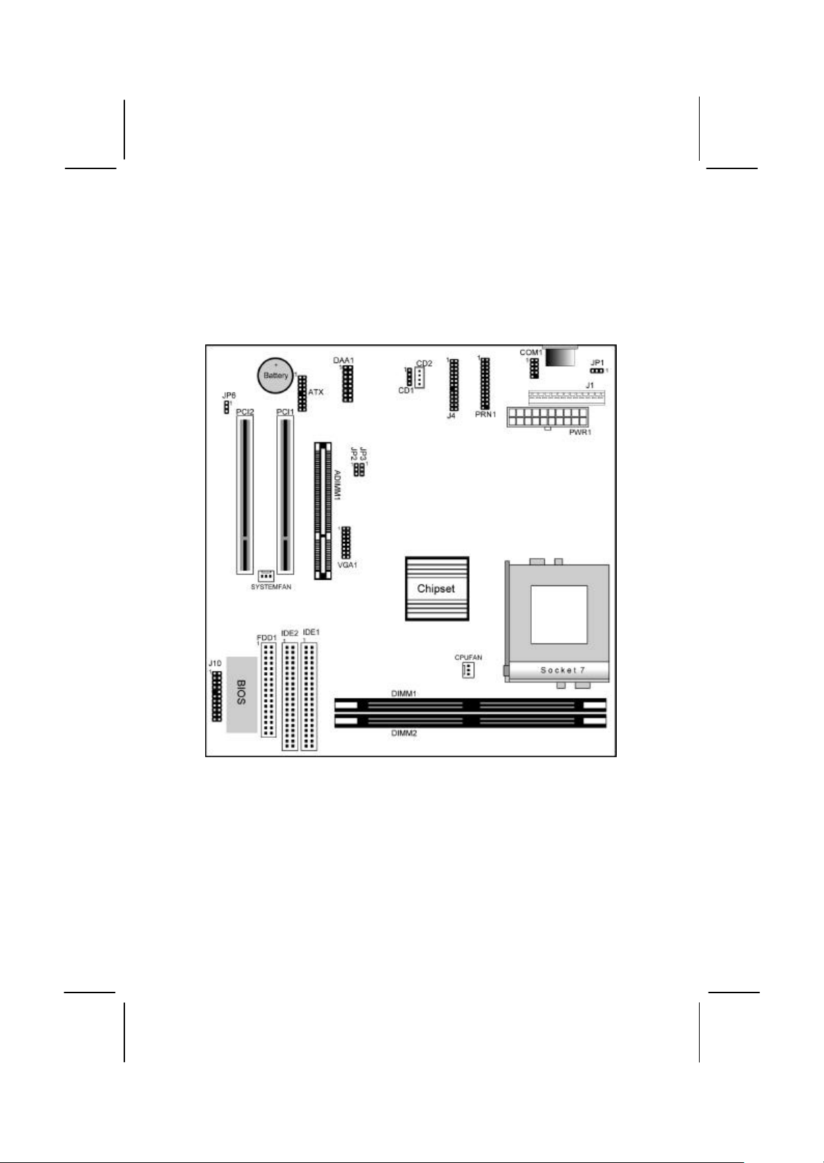
Mainboard Components
Use the diagram below to identify the major components on the
mainboard.
Note: Any jumpers on your mainboard that do not appear in
this illustration are for testing only.
Page 13
2: Mainboard Installation
9
Pin-1 Corner
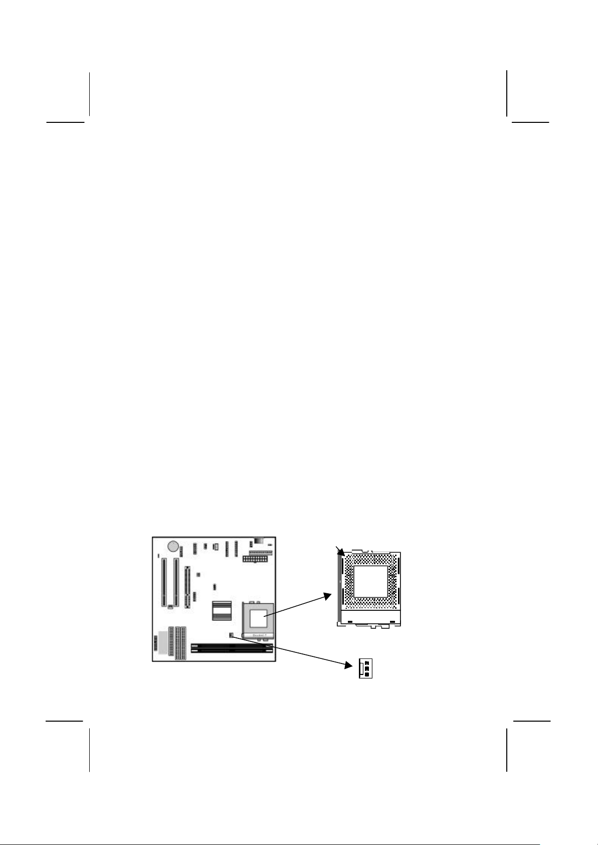
Install A CPU
This mainboard has a Socket-7 which may be installed with any of
the socket-7 processors including the Intel P55C (MMX) series, the
Cyrix/IBM 6x86L/6x86MX/MII series, the AMD K6/K6-2/K-III
series, the IDT C6/Winchip 2/2A series. The mainboard supports
system bus speeds of 66, 100 MHz.
Do not try to install a Socket-370 processor in the Socket-7. A
Socket-370 processor such as the PPGA Celeron or FCPGA
Pentium III does not fit in the Socket-7.
The board supports CPU plug and play, so the system can
automatically run the installed processor with the correct clock
speed and the correct system bus frequency. To automatically
configure the processor, use the BIOS setup program to select the
clock speed and system bus frequency. See chapter three for more
information.
To ensure reliability, make sure that your socket-7 processor is
fitted with a heatsink/cooling fan assembly.
The socket-7 processor installs into the ZIF (Zero Insertion Force)
socket-7 on the mainboard.
1. Locate the Socket-7 and CPUFAN. Pull the locking lever out
slightly from the socket and raise it to the upright position.
Socket-7
CPUFAN
Page 14

MS6391E Mainboard User’s Manual
10
2. On the processor, identify the Pin-1 corner by its beveled edge.
3. On the Socket-7, identify the Pin-1 corner. The Pin-1 corner is
at the end of the locking lever when it is locked.
4. Match the Pin-1 corners and insert the processor into the
socket. No force is required and the processor should drop into
place freely.
5. Swing the locking lever down and hook it under the catch on
the side of the socket. This secures the CPU in the socket.
6. All processors should be installed with a combination
heatsink/cooling fan, connect the cable from the fan to the
CPU fan power connector CPUFAN.
Install Memory
The mainboard has two DIMM sockets for system memory
modules. You must install at least one memory module in order to
use the mainboard.
DIMM1
DIMM2
For this mainboard, you must use 168-pin, 3.3V unbuffered
SDRAM memory modules. If the installed CPU uses a 100 MHz
system bus, you must use PC100 memory. If the installed CPU
uses a 66 MHz system bus, you must use PC66 memory. You can
install any size memory module from 16 MB to 512MB, so the
maximum memory size is 2 x 512MB = 1GB.
The edge connectors on the memory modules have cut outs, which
coincide with spacers in the DIMM sockets so that memory
modules can only be installed in the correct orientation.
Page 15

2: Mainboard Installation
11
JP2 JP3
1 1
JP6
1
JP1
1
To install a module, push the retaining latches at either end of the
socket outwards. Position the memory module correctly and insert
it into the DIMM socket. Press the module down into the socket so
that the retaining latches rotate up and secure the module in place
by fitting into notches on the edge of the module.
Setting Jumper Switches
Jumpers are sets of pins which can be connected together with
jumper caps. The jumper caps change the way the mainboard
operates by changing the electronic circuits on the mainboard. If a
jumper cap connects two pins, we say the pins are SHORT. If a
jumper cap is removed from two pins, the pins are OPEN.
Jumper JP1: Keyboard Power On Selector
If you enable the keyboard power on feature, you can use hot keys
on your keyboard as a power on/off switch for the system.
Note: The system must provide 1A on the +5VSB (+5V Standby)
signal before using the Keyboard Power On function.
Function Jumper Setting
Disable Keyboard Power On Short Pins 1-2
Enable Keyboard Power On Short Pins 2-3
Page 16

MS6391E Mainboard User’s Manual
12
Jumper JP2: Fax/Modem Enable/disable
Use this jumper to enable or disable the onboard Fax/Modem.
Disable the Fax/Modem if you plan on using another Fax/Modem.
Function Jumper Setting
Enable Fax/Modem Short Pins 1-2
Disable Fax/Modem Short Pins 2-3
Note: If you have disabled the onboard audio system with
jumper JP3, the Fax/Modem will not function even if it is
enabled.
Jumper JP3: Audio System Enable/disable
Use this jumper to enable or disable the audio system integrated on
this mainboard. Disable the built-in audio if you plan on using
another audio system on an expansion card.
Function Jumper Setting
Enable Audio Short Pins 1-2
Disable Audio Short Pins 2-3
Note: If you disable the onboard audio system, you cannot
use the onboard Fax/Modem.
Jumper JP6: Clear CMOS Memory
Use this jumper to clear the contents of the CMOS memory. You
may need to clear the CMOS memory if the settings in the Setup
Utility are incorrect and prevent your mainboard from operating.
To clear the CMOS memory, disconnect all the power cables from
the mainboard and then move the jumper cap into the CLEAR
setting for a few seconds.
Function Jumper Setting
Normal Operation Short Pins 1-2
Clear CMOS Memory Short Pins 2-3
Page 17

2: Mainboard Installation
13
SYSTEMFAN
J1: AT
Install the Mainboard
Install the mainboard in a system chassis (case). The board is a
baby-AT size mainboard. However, the board supports an AT and
an ATX power supply so you can use either an AT or ATX system
case. If you use an AT case, some of the ATX power management
features might not function.
Install the mainboard in a case. Follow the instructions provided by
the case manufacturer using the hardware and internal mounting
points on the chassis.
J10
PWR1: ATX
If you are using a case with an ATX power supply, connect the
power cable from the ATX power supply unit to the power
connector PWR1 on the mainboard.
If you are using a case with an AT power supply, connect the
power cable from the AT power supply unit to the power connector
J1 on the mainboard.
If there is a cooling fan installed in the system chassis, connect the
cable from the cooling fan to the SYSTEMFAN fan power
connector on the mainboard.
Connect the case switches and indicator LEDs to the J10 switch
and LED connector header.
Page 18

MS6391E Mainboard User’s Manual
14
Power LED
Speaker
VGA Extension
See the illustration below for a guide to the J10 connector pin
assignments.
1 2
Pins 1-3-5-7
Reset Switch Pins 17-18
Power/Suspend Switch Pins 21-22
Pins 2-4-6
HDD LED Pins 15-16
Suspend LED Pins 19-20
21 22
Install the Extension Brackets
The extension brackets are used to connect features on the
mainboard to external connectors that can be attached to the system
chassis. Follow the steps below to install the extension brackets.
Note: All the ribbon cables used on the extension brackets have a
red stripe on the Pin-1 side of the cable.
VGA Extension Bracket
The VGA extension bracket has a 15-pin connector for an external
monitor cable.
1
VGA Header
Bracket
Page 19

2: Mainboard Installation
15
Line & Tel
1. On the mainboard, locate the VGA header for this bracket.
2. Plug the cable from the bracket into the VGA header.
3. In the system chassis, remove a blanking plate from one of the
expansion slots and install the extension bracket in the slot.
Use the screw that held the blanking plate in place to secure
the extension bracket.
Fax/Modem Module
The Fax/Modem DAA module plugs directly into the mainboard in
line with to an expansion slot opening in the system chassis. When
you remove the slot cover from the system chassis, you can access
the LINE and TEL RJ11 connectors on the metal edge of the
Fax/Modem DAA module.
DAA1-Modem Header
1
1. Locate the Modem header on the mainboard.
2. Plug the Fax/Modem DAA module into the Modem header.
3. Remove the modem header slot cover.
RJ11 Sockets
Modem Header
Modem DAA Module
Page 20

MS6391E Mainboard User’s Manual
16
Audio Ports & Game/MIDI
Stereo Line-in
Stereo Line-out
channels 1-2
Audio Ports and Game/MIDI Port Extension Bracket
This bracket provides three audio jacks for stereo line in, stereo
line out and microphone. In addition it has a 15-pin D-connector
which can be used by either a joystick or a MIDI device.
If you are using a four channel speaker system, channel one and
two are output through the Stereo Line-out, and the rear speaker
channels three and four are output through Stereo Line-in.
1
J4-Sound Header
/Rear speaker
channels 3-4
Microphone
/Speaker
Game/MIDI
Extension Bracket
1. On the mainboard, locate the J4-Sound header for this bracket.
2. Plug the cable from the bracket into the header.
3. In the system chassis, remove a blanking plate from one of the
expansion slots and install the extension bracket in the slot.
Use the screw that held the blanking plate in place to secure
the extension bracket.
Page 21

2: Mainboard Installation
17
Serial Port
Parallel Port
Serial/Parallel Ports
Serial/Parallel Ports Extension Bracket
This bracket has one serial port - COM1 (9-pins) and one parallel
port – LPT1 (25pins).
1
COM1 Header
1
PRN1
COM1
LPT1
Extension Bracket
1. On the mainboard, locate the headers COM1 and PRN1 for this
bracket.
2. Plug the serial cable into COM1 and the parallel cable into
PRN1.
3. In the system chassis, remove a blanking plate from one of the
expansion slots and install the extension bracket in the slot.
Use the screw that held the blanking plate in place to secure
the extension bracket.
Page 22

MS6391E Mainboard User’s Manual
18
LAN Extension
LAN Network Adapter Extension Bracket
This bracket supports an RJ45 network connector and connects to
the built in LAN header LAN1 on the mainboard.
1
LAN Header
Bracket
1. On the mainboard, locate the LAN header for this bracket.
2. Plug the cable from the bracket into the LAN header.
3. In the system chassis, remove a blanking plate from one of the
expansion slots and install the extension bracket in the slot.
Use the screw that held the blanking plate in place to secure
the extension bracket.
Page 23

2: Mainboard Installation
19
PS/2 Mouse
ATX Form Card
This ATX Form card provides a mini-DIN port for infrared, one
mini-DIN port for a PS/2 mouse. In addition it has two USB
(Universal Serial Bus) ports.
1
ATX Header
Infrared Port
Port
USB Ports
ATX Form Card
1. On the mainboard, locate the ATX header for this bracket.
2. Plug the cable from the bracket into the ATX header.
3. In the system chassis, remove a blanking plate from one of the
expansion slots and install the extension bracket in the slot.
Use the screw that held the blanking plate in place to secure
the extension bracket.
Page 24

MS6391E Mainboard User’s Manual
20
FDD1
1 1
Install Other Devices
Install and connect any other devices in the system following the
steps below.
IDE2
1
Floppy Disk Drive
The mainboard ships with a floppy disk drive cable that can
support one or two drives. Drives can be 3.5” or 5.25” wide, with
capacities of 360K, 720K, 1.2MB, 1.44MB, or 2.88MB.
Install your drives and connect power from the system power
supply. Use the cable provided to connect the drives to the floppy
disk drive header FDD1.
IDE1
IDE Devices
IDE devices include hard disk drives, high-density diskette drives,
and CD-ROM or DVD-ROM drives, among others.
The mainboard ships with an IDE cable that can support one or two
IDE devices. If you connect two devices to a single cable, you
must configure one of the drives as Master and one of the drives as
Slave. The documentation of the IDE device will tell you how to
configure the device as a Master or Slave device. The Master
device connects to the end of the cable.
Install the device(s) and connect power from the system power
supply. Use the cable provided to connect the device(s) to the
Primary IDE channel connector IDE1 on the mainboard.
If you want to install more IDE devices, you can purchase a second
IDE cable and connect one or two devices to the Secondary IDE
channel connector IDE2 on the mainboard. If you have two
devices on the cable, one must be Master and one must be Slave.
Page 25

2: Mainboard Installation
21
CD1
1
Internal Sound Connections
If you have installed a CD-ROM drive or DVD-ROM drive, you
can connect the drive audio cable to the onboard sound system.
On the mainboard, locate the two 4-pin connectors CD1 and CD2.
There are two kinds of connector because different brands of CDROM drive have different kinds of audio cable connectors.
Connect the cable to the appropriate connector.
CD2
Expansion Slots
This mainboard has two 32-bit PCI expansion slots and one
optional ADIMM slot. The PCI slot PCI2 is shared with the USB
port. It means that you can use either one of shared both but you
cannot use the both at the same time.
PCI2 PCI1
ADIMM1
Follow the steps below to install a PCI or ADIMM expansion card.
Page 26

MS6391E Mainboard User’s Manual
22
1. Select a free PCI or ADIMM slot on the mainboard.
2. Remove the slot cover for the expansion slot from the system
chassis.
3. Insert the expansion card edge connector into the slot and press
it firmly down into it so that it is fully inserted.
4. Secure the expansion card bracket to the system chassis using
the screw that held the slot cover in place.
ADIMM slot
ADIMM stands for Advanced Double In-line Memory Module.
Use this slot to install a display cache card or video bridge card.
You can purchase an optional SiS301 video bridge card which
supports an NTSC/PAL video encoder with a Macrovision V7.1.L1
option for TV display, a TMDS® transmitter with bi-linear scaling
capability for a TFT LCD panel display, or an analog RGB port to
support a secondary CRT monitor display. These functions support
dual-display features. The second display can display independent
resolutions, color depths and frame rates different from the primary
VGA display. The card receives digital video signals and control
signals from the VGA circuitry and transforms them into
composite or component video output for a TV display, TMDS
®
signals for an LCD display or analog RGB signals for a secondary
CRT display.
Page 27

MS6391E Mainboard User’s Manual
Chapter 3
BIOS Setup Utility
Introduction
The BIOS Setup Utility records settings and information about
your computer such as the date and time, the kind of hardware
installed, and various configuration settings. Your computer uses
this information to initialize all the components when booting up
and functions as the basis for coordination between system
components.
If the Setup Utility configuration is incorrect, it may cause the
system to malfunction. It can even stop your computer from
booting properly. If this happens, you can use the clear CMOS
jumper to clear the CMOS memory used to store the configuration
information, or you can hold down the Page Up key while you
reboot your computer. Holding down the Page Up key also clears
the CPU PnP Setup information, you may need to set the CPU
speed again.
You can run the setup utility and manually make changes to the
configuration. You might need to do this to configure some of the
hardware that you install on or connect to the mainboard, such as
the CPU, system memory, disk drives, etc.
23
Page 28

MS6391E Mainboard User’s Manual
24
Running the Setup Utility
Each time your computer starts, before the operating system loads,
a message appears on the screen that prompts you to “Hit <DEL>
if you want to run SETUP ”. When you see this message, press the
Delete key and the Main menu page of the Setup Utility appears on
your monitor.
AMIBIOS SIMPLE SETUP UTILITY – VERSION 1.20e
©2000 American Megatrends, Inc. All Rights Reserved
Standard CMOS Setup Features Setup
Advanced Setup CPU PnP Setup
Power Management Setup Hardware Monitor
PCI / Plug and Play Setup Change Password
Load Optimal Settings Exit
Load Best Performance Settings
ESC: Quit ↑↓←→ : Select Item (Shift)F2 : Change Color F5 : Old Values
F6: Optimal values F7: Best performance values F10: Save&Exit
You can use the cursor arrow keys to highlight any of the options
on the main menu page. Press Enter to select the highlighted
option. To leave the setup utility, press the Escape key. To cycle
through the Setup Utility’s optional color schemes hold down the
Shift key and press F2.
Some of the options on the main menu page lead to tables of items
with installed values. In these pages, use the cursor arrow keys to
highlight the items, and then use the PgUp and PgDn keys to cycle
through the alternate values for each of the items. Other options on
the main menu page lead to dialog boxes which require you to
answer Yes or No by hitting the Y or N keys.
If you have already made changes to the setup utility, press F10 to
save those changes and exit the utility. Press F5 to reset the
changes to the original values. Press F6 to install the setup utility
with a set of default values. Press F7 to install the setup utility with
a set of high-performance values.
Page 29

3: BIOS Setup Utility
25
Use these items to set the system date and time
Standard CMOS Setup Page
Use this page to set basic information such as the date and time, the
IDE devices, and the diskette drives. If you press the F3 key, the
system will automatically detect and configure the hard disks on
the IDE channels.
AMIBIOS SETUP – STANDARD CMOS SETUP
©2000 American Megatrends, Inc. All Rights Reserved
Date (mm/ dd/yy) : Mon May 22, 2000
Time (hh/mm/ss) : 14:26:53
LBA Blk PIO 32Bit
Type Size Cyln Head WPcom Sec Mode Mode Mode Mode
Pri Master : Auto On
Pri Slave : Auto On
Sec Master : Auto On
Sec Slave : Auto On
Floppy Drive A : 1.44MB 3 1/2”
Floppy Drive B : Not Installed
Month : Jan – Dec ESC : Exit
Day : 01 – 31 éê : Select Item
Year : 1901 – 2099 PU/PD/+/- : Modify
(Shift)F2 : Color
F3 : Detect All HDD
Date & Time
Pri Master
Pri Slave
Sec Master
Sec Slave
Floppy Drive A
Floppy Drive B
Use these items to configure devices connected
to the Primary and Secondary IDE channels. To
configure an IDE hard disk drive, choose Auto. If
the Auto setting fails to find a hard disk drive, set
it to User, and then fill in the hard disk
characteristics (Size, Cyls, etc.) manually. If you
have a CD-ROM drive, select the setting
CDROM . If you have an ATAPI device with
removable media (e.g. a ZIP drive or an LS-120)
select Floptical.
Use these items to set the size and capacity of
the floppy diskette drive(s) installed in the
system.
Page 30

MS6391E Mainboard User’s Manual
26
Advanced Setup Page
Use this page to set more advanced information about your system.
Take some care with this page. Making changes can affect the
operation of your computer.
AMIBIOS SETUP – ADVANCED SETUP
©2000 American Megatrends, Inc. All Rights Reserved
Trend ChipAwayVirus Enabled
Frame Buffer Cache Control Auto
Share Memory Size 8MB
1st Boot Device IDE-0
2nd Boot Device Floppy
3rd Boot Device CDROM
Try Other Boot Devices Yes
S.M.A.R.T. for Hard Disks Disabled
BootUp Num-Lock On
Floppy Drive Swap Disabled
Floppy Drive Seek Disabled
Password Check Setup
Boot To OS/2 > 64MB No
Internal Cache Enabled
External Cache Enabled
System BIOS Cacheable Disabled ESC : Quit ↑↓←→ : Select Item
F1 : Help PU/PD/+/- : Modify
F5 : Old Values (Shift)F2 : Color
F6 : Load Optimal values
F7 : Load Best performance values
Trend ChipAway
Virus
Frame Buffer
Cache Control
Share Memory
Size
1st Boot Device
2nd Boot Device
3rd Boot Device
Try Other Boot
Device
S.M.A.R.T. for
Hard Disks
This mainboard has built-in virus protection in the
firmware. Use this item to enable or disable the
built-in virus protection.
This item appears when a Frame Buffer Cache
card is installed in the ADIMM socket. The default
setting, Auto, automatically sets the display
memory size. The Manual setting uses the next
item to manually set display memory size.
This item lets you allocate a portion of the main
memory for use by the onboard VGA display.
Use these items to determine the device order
the computer uses to look for an operating
system to load at start-up time.
If you enable this item, the system will also
search for other boot devices if it fails to find an
operating system from the first two locations.
Enable this item if any IDE hard disks support the
S.M.A.R.T. (Self-Monitoring, Analysis and
Reporting Technology) feature.
Page 31

3: BIOS Setup Utility
27
BootUp NumLock
Floppy Drive
Swap
Floppy Drive
Seek
Password Check If you have entered a password for the system,
Boot to OS/2 >
64MB
Internal Cache
External Cache
System BIOS
Cacheable
This items determines if the Num Lock key is
active or inactive at system start-up time.
If you have two diskette drives installed and you
enable this item, drive A becomes drive B and
drive B becomes drive A.
If you enable this item, your system will check all
floppy disk drives at start up. Disable this item
unless you are using an old 360KB drive.
use this item to determine if the password is
required to enter the Setup Utility (Setup) or
required both at start-up and to enter the Setup
Utility (Always).
Enable this item if you are booting the OS/2
operating system and you have more than 64MB
of system memory installed.
Leave this item enabled since all the processors
that can be installed on this board have internal
cache memory.
Leave this item enabled since all the processors
that can be installed on this board have external
cache memory.
If you enable this item, a segment of the system
BIOS will be cached to main memory for faster
execution.
Page 32

MS6391E Mainboard User’s Manual
28
Power Management Setup Page
This page sets some of the parameters for system power
management operation.
AMIBIOS SETUP – POWER MANAGEMENT SETUP
©2000 American Megatrends, Inc. All Rights Reserved
Power Management/APM Disabled
Standby Time Out (Minute) Disabled
Suspend Time Out (Minute) Disabled
Hot Key Power On Disabled
LAN Card Power On Disabled
Ring On Power On Disabled
RTC Alarm Power On Disabled
RTC Alarm Date 15
RTC Alarm Hour 12
RTC Alarm Minute 30
RTC Alarm Second 30
ESC : Quit ↑↓←→ : Select Item
F1 : Help PU/PD/+/- : Modify
F5 : Old Values (Shift)F2 : Color
F6 : Load Optimal values
F7 : Load Best performance values
Power
Management/APM
Standby Time Out
(Minute)
Suspend Time Out
(Minute)
Hot Key Power On
Use this item to enable or disable a power
management scheme. If you enable power
management, you can use the items below to
set the power management operation. Both
APM and ACPI are supported.
This sets the timeout for Standby mode in
minutes. If the time selected passes without any
system activity, the computer will enter powersaving Standby mode.
This sets the timeout for Suspend mode in
minutes. If the time selected passes without any
system activity, the computer will enter powersaving Suspend mode.
If you enable this item, you can turn the system
on by pressing hot keys (Ctrl + Alt + Back
Space) on the keyboard. You must connect an
ATX power supply and enable this function
jumper in order to use this feature.
Page 33

3: BIOS Setup Utility
29
LAN Card Power
On
Ring On Power On The system can be turned off with a software
RTC Alarm Power
On
/Date
/Hour
/Minute
/Second
The system can be turned off with a software
command. If you enable this item, the system
can automatically resume if there is traffic on
the network adapter. You must use an ATX
power supply in order to use this feature.
command. If you enable this item, the system
can automatically resume if there is an
incoming call on the Fax/Modem. You must use
an ATX power supply in order to use this
feature.
The system can be turned off with a software
command. If you enable this item, the system
can automatically resume at a fixed time based
on the system’s RTC (realtime clock). Use the
items below this one to set the date and time of
the wake-up alarm. You must use an ATX
power supply in order to use this feature.
Page 34

MS6391E Mainboard User’s Manual
30
PCI / Plug and Play Setup Page
This page sets some of the parameters for devices installed on the
PCI bus and devices that use the system plug and play capability.
AMIBIOS SETUP – PCI / PLUG AND PLAY SETUP
©2000 American Megatrends, Inc. All Rights Reserved
Plug and Play Aware O/S Yes
Primary Graphics Adapter PCI
Allocate IRQ to PCI VGA Yes
Reserved Memory Size Disabled
ESC : Quit ↑↓←→ : Select Item
F1 : Help PU/PD/+/- : Modify
F5 : Old Values (Shift)F2 : Color
F6 : Load Optimal values
F7 : Load Best performance values
Plug and Play
Aware O/S
Primary Graphics
Adapter
Allocate IRQ to
PCI VGA
Reserved Memory
Size
Enable this item if you are using an O/S that
supports Plug and Play such as Windows 95 or
98.
This item indicates if the primary graphics
adapter uses the PCI or the AGP bus. The
default PCI setting still lets the onboard display
work and allows the use of a second display
card installed in a PCI slot.
If this item is enabled, an IRQ will be assigned
to the PCI VGA graphics system. You set this
value to No to free up an IRQ.
This item lets you reserve a block of memory
for any device that requires it.
Page 35

3: BIOS Setup Utility
31
Load Optimal Settings
If you select this item and press Enter a dialog box appears. If you
press Y, and then Enter, the Setup Utility loads a set of fail-safe
default values. These default values are not very demanding and
they should allow your system to function with most kinds of
hardware and memory chips.
Load Best Performance Settings
If you select this item and press Enter a dialog box appears. If you
press Y, and then Enter, the Setup Utility loads a set of best-
performance default values. These default are quite demanding and
your system might not function properly if you are using slower
memory chips or other low-performance components.
Features Setup Page
This page sets some of the parameters for peripheral devices
connected to the system.
AMIBIOS SETUP – FEATURES SETUP
OnBoard FDC Enabled
OnBoard Serial PortA 3F8h/COM1
OnBoard IR Port Disabled
OnBoard Parallel Port 378h
Parallel Port Mode SPP
Parallel Port IRQ 7
Parallel Port DMA N/A
OnBoard PCI IDE Both
Ultra DMA Support Disabled
OnBoard Audio/Modem Enabled
OnBoard LAN Enabled
USB Function Disabled
USB Function for DOS Disabled
ESC : Quit ↑↓←→ : Select Item
F1 : Help PU/PD/+/- : Modify
F5 : Old Values (Shift)F2 : Color
F6 : Load Optimal values
F7 : Load Best performance values
OnBoard FDC
©2000 American Megatrends, Inc. All Rights Reserved
Use this item to enable or disable the onboard
floppy disk drive interface.
Page 36

MS6391E Mainboard User’s Manual
32
OnBoard Serial
PortA
OnBoard IR Port
Onboard Parallel
Port
Parallel Port Mode
Parallel Port IRQ
Parallel Port DMA
Onboard PCI IDE Use this item to enable or disable either or both
Ultra DMA Support
Onboard Audio/
Modem
Onboard LAN Use this item to enable or disable the onboard
USB Function Enable this item if you plan to use the USB
USB Function for
DOS
Use this item to enable or disable the onboard
COM1 serial port, and to assign a port address
Use this item to define the protocol for an
infrared port if you have installed an optional IR
port. The choices are IrDA and ASKIR.
Use this item to enable or disable the onboard
LPT1 parallel port, and to assign a port
address. The Auto setting will detect and
available address.
Use this item to set the parallel port mode. You
can select SPP (Standard Parallel Port), ECP
(Extended Capabilities Port), EPP (Enhanced
Parallel Port), or ECP + EPP.
Use this item to assign either IRQ 5 or 7 to the
parallel port.
Use this item to assign a DMA channel to the
parallel port. The options are 0, 1 and 3.
of the onboard Primary and Secondary IDE
channels.
Use this item to set Ultra DMA support for IDE
devices on the Primary or Secondary IDE
channels. You must enable this or UDMA
devices will not work at their intended speed.
Use this item to enable or disable the onboard
audio/modem chip.
network interface.
ports on this mainboard.
Enable this item if you plan to use the USB
ports on this mainboard in a DOS environment.
Page 37

3: BIOS Setup Utility
33
CPU PnP Setup Page
This page lets you manually configure the mainboard for the CPU.
The system will automatically detect the kind of CPU that you
have installed and make the appropriate adjustments to the items
on this page.
Note: If you manually set the wrong speed and the system won’t
run properly, press the Page Up key while the system is booting
and a default setting will replace the incorrect CPU setting.
AMIBIOS SETUP – CPU PnP SETUP
©2000 American Megatrends, Inc. All Rights Reserved
CPU Plug and Play Auto
CPU Brand
VCCore Voltage 2.0V
CPU Speed 450 MHz
CPU Base Frequency 100 MHz
CPU Multiple Factory X4.5
E-Plus CPU installed Disable
ESC : Quit ↑↓←→ : Select Item
F1 : Help PU/PD/+/- : Modify
F5 : Old Values (Shift)F2 : Color
F6 : Load Optimal values
F7 : Load Best performance values
CPU Plug and Play
CPU Brand;
VCCore Voltage
CPU Speed
CPU Base
Frequency
CPU Multiple
Factor
E-Plus CPU
installed
Use this item to select the CPU Plug and Play
function by auto-detect or user-define.
These items display the CPU brand and CPU
core voltage by the system automatic detecting.
The item displays the internal clock speed of
the CPU, based on the next two items.
Use this item to set the external clock frequency
for the CPU. Set the CPU clock based on the
requirements of the CPU installed on the board.
Use this item to set a multiplier for the CPU
external frequency. The multiplier times the
external CPU frequency sets the internal clock
speed of the CPU, e.g. 100 MHz (external clock
or “FSB”) x 4.5 (muliplier) = 450 MHz (internal
clock speed of the installed CPU).
Enable this item if you plan to use the AMD EPlus CPU on this mainboard.
Page 38

MS6391E Mainboard User’s Manual
34
Hardware Monitor Page
This page sets some of the parameters for the hardware monitoring
function of this mainboard.
AMIBIOS SETUP – HARDWARE Monitor
©2000 American Megatrends, Inc. All Rights Reserved
--- Hardware Monitor --CPU Temperature 30°C/86°F
System Temperature 30°C/86°F
CPU Fan Speed
Chassis Fan Speed
Vcore 2.000 V
+1.800V 1.800 V
Vcc3 3.300 V
Vcc 5.000 V
+12V 12.000 V
SB5V 5.000 V
ESC : Quit ↑↓←→ : Select Item
F1 : Help PU/PD/+/- : Modify
F5 : Old Values (Shift)F2 : Color
F6 : Load Optimal values
F7 : Load Best performance values
CPU / System
Temperature
FAN Speeds &
Voltage
Measurements
These items display CPU/system temperature
measurement.
These items indicate cooling fan speeds in
RPM and the various system voltage
measurements.
Change Password
If you highlight this item and press Enter, a dialog box appears
which lets you enter a Supervisor password. You can enter no more
than six letters or numbers. Press Enter after you have typed in the
password. A second dialog box asks you to retype the password for
confirmation. Press Enter after you have retyped it correctly. The
password is then required to access the Setup Utility or for that and
at start-up, depending on the setting of the Password Check item
in Advanced Setup.
Page 39

3: BIOS Setup Utility
35
Change or Remove the Password
Highlight this item, press Enter and type in the current password.
At the next dialog box, type in the new password, or just press
Enter to disable password protection.
Exit
Highlight this item and press Enter to save the changes that you
have made in the Setup Utility configuration and exit the program.
When the Save and Exit dialog box appears, press Y to save and
exit, or press N to exit without saving.
Page 40

4: Software & Applications
Chapter 4
Software & Applications
Introduction
The support software CD-ROM that is included in the mainboard
package contains all the drivers and utility programs needed to
properly run our products. Please check all the README files for
the latest information on installing and using the software.
Using the PCI Sound Application
1. Before you install the PCI Sound drivers, make sure your
Operating System has been installed, otherwise the PCI Sound
might be detected as “Other device” by the device manager of
your OS.
2. After the drivers are properly installed, choose the
MULTIMEDIA icon in the CONTROL PANEL when you
need to use the Software Wave-Table drivers as a MIDI output
device. Select the MIDI page and click on “C-media SoftMidi
Synthesis (Win98) / Driver (Win95) ”, then click “OK” to
confirm.
3. A Windows application named Audio Rack is provided with
the PCI Sound drivers, which gives you control over all the
audio functions through a user interface that is as simple to use
as a home stereo system. We recommend that you use the
System Mixer in the Audio Rack software to control your
computer ’s audio volume, recording device and the recording
gain.
36
Page 41

4: Software & Applications
37
4. If the devices that you are using require the MIDI port as the
control interface, you need to select the MULTIMEDIA icon
in the CONTROL PANEL. Select the MIDI page and click on
“CM8738 MPU-401” (Win98) or “CM8738/C3DX PCI Audio
External MIDI Port” (Win95), and then click “OK” to confirm.
5. For more information, refer to the PCI Sound manual in the
CD which ships with this mainboard.
The Four Speakers System
The onboard Sound Pro audio system supports 2 wave channels
(front/rear) known as the 4 speaker system. If you are running
applications which use the DirectSound® 3D or A3D® audio
interface, your system can simulate realistic 3D sound through a 4
speaker setup. Follow the steps below to install a 4-speaker setup.
Speaker Installation
Connect the front two speakers to the Line-out jack on the sound
ports extension bracket. Connect the rear two speakers to the Linein/Rear jack on the sound ports extension bracket. The original
Line-in can be moved to Aux.
Speaker Position
Set up your speakers similar to the following figure to get the best
audio result.
Page 42

MS6393E Mainboard User’s Manual
38
Mixer Setup
There is a 4-speakers option in the Volume Control of the Mixer
when you are setting up the PCI Audio Application. Click on the 4
SPK icon to enable this option. This means that the output to the
rear speakers is sent through the Line-in/Rear jack. In order to
avoid hardware conflicts, DO NOT enable this option when the
Line-in/Rear jack is connected with a line-in device. While the 4
speakers mode is enabled, turn on/off the output of the front
speakers and adjust the volume of the speakers so that the
front/rear speakers have the same volume.
Demo
Execute the “Helicopter ” demo in the C3D HRTF Positional Audio
Demos of the PCI Audio Application. When you hear the
helicopter flying behind you, it means that the rear speakers are
working properly.
 Loading...