

Page 1

Matrox Meteor-II
Installation and Hardware Reference
Manual no. 10577-101-0300
December 9, 1999
Page 2

Matrox® is a registered trademark of Matrox Electronic Systems Ltd.
Microsoft®, MS-DOS®, Windows®, and Windows NT® are registered
trademarks of Microsoft Corporation.
®
Intel
, Pentium®, and Pentium II® are registere d t rademarks of Intel
Corporatio n.
Texas Instrume nts is a tradema rk of Tex as Instruments Incorporated.
PC/104-Plus™ is a trademark of the PC/104 Consortium.
CompactPCI™ is a trademark of PCI Industrial Computer
Manuf acturers’ Group.
RAMDAC™ is a trademark of Booktree.
All other nationally and internationally recognized trademarks and
tradenames are hereby acknowledged.
© Copyright Matrox Electronic Systems Ltd., 1999. All rights re served.
Disclaimer: Ma trox Electronic Sy stems Ltd. reserve s the right to make
changes in specifications at any time and without notice. The
information provided by this document is believed to be accurate and
reliable. However, no responsibility is assumed by Matrox Electronic
Systems Ltd. for its use; nor for any infringements of patents or other rights
of third parti es result in g f r om it s u se. No license is grante d u nd er any
patents or patent r ig hts of Matrox Electronic Systems Ltd .
PRINTED IN CANADA
Page 3

Contents
Chapter 1: Introduction . . . . . . . . . . . . . . . . . . . . . . . . . . . 9
Matrox Meteor-II boards . . . . . . . . . . . . . . . . .10
Matrox Meteor-II /Standard . . . . . . . . . . . .10
Matrox Meteor-II /Multi-Channel . . . . . . . .11
Matrox Meteor-II /Digital . . . . . . . . . . . . . .13
Matrox Meteor-II /1394 . . . . . . . . . . . . . . .14
Matrox Meteor-II MJPEG module . . . . . . . .15
Data transfer . . . . . . . . . . . . . . . . . . . . . . .16
Software. . . . . . . . . . . . . . . . . . . . . . . . . . .16
What you need to get started. . . . . . . . . . . . . .18
Inspecting the Matrox Meteor-II package. . . . .19
Standard package. . . . . . . . . . . . . . . . . . . .19
Optional items . . . . . . . . . . . . . . . . . . . . . .19
Handling components. . . . . . . . . . . . . . . . .20
Installation overview . . . . . . . . . . . . . . . . . . . .21
Chapter 2: Hardware installation . . . . . . . . . . . . . . . . . .23
Installing Matrox Meteor-II . . . . . . . . . . . . . . .24
Installing Matrox Meteor-II for PCI . . . . . . .24
Installing Matrox Meteor-II for
CompactPCI . . . . . . . . . . . . . . . . . . . . . . . .27
Installing Matrox Meteor-II for
PC/104-Plus. . . . . . . . . . . . . . . . . . . . . . . .29
Installing the Matrox Meteor-II
MJPEG module. . . . . . . . . . . . . . . . . . . . . . . .31
Page 4

Connecting external devices . . . . . . . . . . . . . . 33
Matrox Meteor-II /Standard for PCI. . . . . . 33
Matrox Meteor-II /Standard for
CompactPCI. . . . . . . . . . . . . . . . . . . . . . . . 36
Matrox Meteor-II /Multi-Channel for PCI. . 37
Matrox Meteor -II /Standard and
/Multi-Channel for PC/104-Plus . . . . . . . . 39
Matrox Meteor-II /Digital. . . . . . . . . . . . . . 40
Matrox Meteor-II /1394 . . . . . . . . . . . . . . . 42
Chapter 3: Installing softwar e. . . . . . . . . . . . . . . . . . . . .45
Installing the software . . . . . . . . . . . . . . . . . . 46
Note about Matrox Intellicam . . . . . . . . . . . . . 46
Chapter 4: Using multiple M atrox Meteor-II boards . . 47
Using multiple Matrox Meteor-II boards . . . . . 48
Multiple board installation . . . . . . . . . . . . . . . 48
Grabbing simultaneously from different
boards . . . . . . . . . . . . . . . . . . . . . . . . . . . . . . 50
Chapter 5: Matrox Meteor-II hardware reference. . . . 53
Matrox Meteor-II hardware reference . . . . . . . 54
Matrox Meteor-II /Standard grab section . . . . 54
Input channels . . . . . . . . . . . . . . . . . . . . . 55
Low-pass filter . . . . . . . . . . . . . . . . . . . . . . 55
Video decoder . . . . . . . . . . . . . . . . . . . . . . 55
UART . . . . . . . . . . . . . . . . . . . . . . . . . . . . 56
Trigger. . . . . . . . . . . . . . . . . . . . . . . . . . . . 56
User bits . . . . . . . . . . . . . . . . . . . . . . . . . . 57
Using the auxiliary power supply . . . . . . . . 57
Page 5

Matrox Meteor-II /Multi-Channel
grab section . . . . . . . . . . . . . . . . . . . . . . . . . .58
Input channels . . . . . . . . . . . . . . . . . . . . . .59
Low-pass filter . . . . . . . . . . . . . . . . . . . . . .59
Gain . . . . . . . . . . . . . . . . . . . . . . . . . . . . . .59
Triple A/D converter. . . . . . . . . . . . . . . . . .60
PSG . . . . . . . . . . . . . . . . . . . . . . . . . . . . . .60
Phase-locked loop. . . . . . . . . . . . . . . . . . . .60
General synchronization . . . . . . . . . . . . . . .61
Trigger . . . . . . . . . . . . . . . . . . . . . . . . . . . .62
UART . . . . . . . . . . . . . . . . . . . . . . . . . . . . .63
Lookup table (LUT) . . . . . . . . . . . . . . . . . . .63
User bits. . . . . . . . . . . . . . . . . . . . . . . . . . .63
Using the auxiliary power supply . . . . . . . .64
Matrox Meteor-II /Digital grab section. . . . . . .64
UART . . . . . . . . . . . . . . . . . . . . . . . . . . . . .66
Lookup table (LUT) . . . . . . . . . . . . . . . . . . .66
PSG . . . . . . . . . . . . . . . . . . . . . . . . . . . . . .66
Control signals . . . . . . . . . . . . . . . . . . . . . .66
Matrox Meteor-II /1394 . . . . . . . . . . . . . . . . .68
Data interfaces . . . . . . . . . . . . . . . . . . . . . . . .70
Video Interface ASIC . . . . . . . . . . . . . . . . . .70
PCI interface. . . . . . . . . . . . . . . . . . . . . . . .70
VMChannel. . . . . . . . . . . . . . . . . . . . . . . . .71
Matrox Meteor-II MJPEG Module . . . . . . . . . .71
Page 6

Append ix A: Troubleshooting. . . . . . . . . . . . . . . . . . . . .75
Troubleshooting . . . . . . . . . . . . . . . . . . . . . . . 76
Common problems and solutions . . . . . . . . . . 76
Installation Problems. . . . . . . . . . . . . . . . . 76
Grabbing Problems . . . . . . . . . . . . . . . . . . 78
Contacting Matrox . . . . . . . . . . . . . . . . . . . . . 80
Append ix B: Technical information Matrox Meteor-II
/Standard
. . . . . . . . . . . . . . . . . . . . . . . . . . . . . . . . . . . . .81
Technical information . . . . . . . . . . . . . . . . . . 82
General information. . . . . . . . . . . . . . . . . . 82
Board input and output connectors . . . . . . . . 83
Video input connector on Matrox Meteor-II
for PCI and CompactPCI . . . . . . . . . . . . . . 85
Video input connector on Matrox Meteor-II
/Standard for PC/104- Plus . . . . . . . . . . . . 87
VMChannel interface connector . . . . . . . . . 88
BNC connector . . . . . . . . . . . . . . . . . . . . . 90
Auxiliary power supply input . . . . . . . . . . . 90
Auxiliary power supply selection . . . . . . . . 91
Specifications. . . . . . . . . . . . . . . . . . . . . . . . . 92
Electrical . . . . . . . . . . . . . . . . . . . . . . . . . . 92
Environmental. . . . . . . . . . . . . . . . . . . . . . 92
Page 7

Appendix C: Technica l information Matrox Me te or- II
/Multi-Channel
Technical information . . . . . . . . . . . . . . . . . . .94
Global information . . . . . . . . . . . . . . . . . . .94
Technical features: . . . . . . . . . . . . . . . . . . .94
Board input and output connectors. . . . . . . . .95
Video input connector on the PCI
form factor . . . . . . . . . . . . . . . . . . . . . . . . .96
Video input connector on the Meteor-II
/Multi-Channel for PC/104-Plus. . . . . . . . .98
VMChannel interface connector . . . . . . . . .99
Auxiliary power supply input . . . . . . . . . . .99
Auxiliary power supply selection . . . . . . . . .99
Specifications . . . . . . . . . . . . . . . . . . . . . . . .100
Electrical . . . . . . . . . . . . . . . . . . . . . . . . .100
Environmental . . . . . . . . . . . . . . . . . . . . .100
. . . . . . . . . . . . . . . . . . . . . . . . . . . . . . . . .93
Appendix D: Technical information
Matrox Meteor-II /Digital
Technical information . . . . . . . . . . . . . . . . . .102
Global information . . . . . . . . . . . . . . . . . .102
Board input and output connectors. . . . . . . .103
Digital interface connector . . . . . . . . . . . .104
RS-232 input connector . . . . . . . . . . . . . .106
Trigger input connector . . . . . . . . . . . . . .106
VMChannel interface connector . . . . . . . .107
Jumpers. . . . . . . . . . . . . . . . . . . . . . . . . .107
. . . . . . . . . . . . . . . . . . . . . . . .101
Page 8

Specifications. . . . . . . . . . . . . . . . . . . . . . . . 108
Electrical . . . . . . . . . . . . . . . . . . . . . . . . . 108
Environmental. . . . . . . . . . . . . . . . . . . . . 108
Appendix E: Technical info r m at ion
Matrox Meteor-II /1394
Technical information . . . . . . . . . . . . . . . . . 110
Global information. . . . . . . . . . . . . . . . . . 110
Board input and output connectors . . . . . . . 111
IEEE 1394 ports . . . . . . . . . . . . . . . . . . . 111
Auxiliary power supply input . . . . . . . . . . 112
References . . . . . . . . . . . . . . . . . . . . . . . . . . 112
Specifications. . . . . . . . . . . . . . . . . . . . . . . . 113
Electrical . . . . . . . . . . . . . . . . . . . . . . . . . 113
Environmental . . . . . . . . . . . . . . . . . . . . 113
. . . . . . . . . . . . . . . . . . . . . . . . . 109
Appendix F: Listing of Matrox Meteor-II Boards. . . . . 115
Matrox Meteor-II boards. . . . . . . . . . . . . . . . 116
Appendix G: Glossary . . . . . . . . . . . . . . . . . . . . . . . . . . 119
Index
Customer Support
Page 9

Chapter 1: Introduction
This chapter outlines the key features of Matrox Meteor-II
boards.
Page 10
10 Chapter 1: Introduction
Matrox Meteor-II boards
Matrox Meteor-II comes in four versions: Matrox Meteor-II
/Standard, Matrox Meteor-II /Multi-Channel, Matrox
Meteor-II /Digital, and Matrox Meteor-II / 1 394. Some of t hese
boards are available in different form factors, namely PCI,
CompactPCI, and PC/104-Plus. All boards and form factors
support real time image transfer to Host memory, and can be
programmed with the Matrox Imaging Library (MIL) or any of
its derivative s.
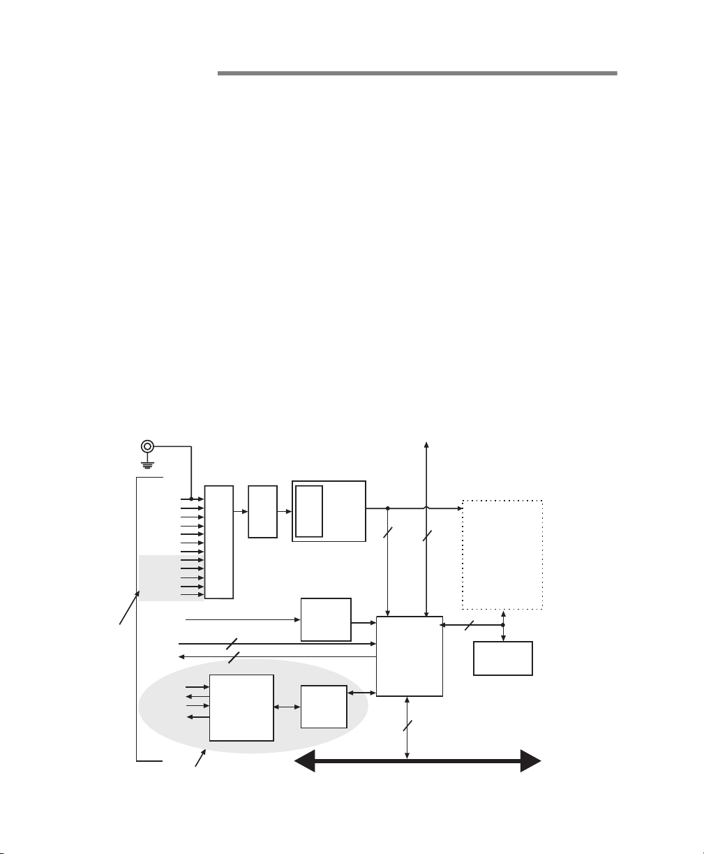
Matrox Meteor-II /Standard
Matrox Meteor-II /Standard is a standard monochrome and
color analog frame grabber. This board is available in a PCI,
PC/104-Plus, or CompactPCI (3U) form factor, all of which can
use a Matrox Meteor-II MJPEG module for compression and
decompression of mo no chrome and color imag es.
BNC Connector for
PCI and Compact
PCI form factors
To DB-44
Connector for
PCI and Compact
PCI form factors
To 30-pin male,
right-angle
connector for
PC/104-Plus
form factor
Not available on
CompactPCI
form factor
VID_IN1
VID_IN2
VID_IN3
VID_IN4
VID_IN5
VID_IN6
VID_IN7
VID_IN8
VID_IN9
VID_IN10
VID_IN11
VID_IN12
Trigger
Aux
RX
TX
/RTS
/CTS
Not available on PC/104-Plus
form factor
12:1
MUX
2
{
2
RS-232
drivers &
receivers
Low
Pass
Filter
Gain
Decoder
Opto-
coupler
UART
VMChannel (not available
on CompactPCI and
PC/104-Plus)
24
32
64
VIA
32
Host 32-bit PCI bus
MJPEG
Module
(optional)
SGRAM
(4 Mbytes)
Page 11

Matrox Meteor-II boards 11
Acquis ition feat ures Matrox Meteor-II /Standard can acquire different types of
standard vide o formats using its video dec o der. The video
decoder can accept composite (CVBS) and component (Y/C)
video in NTSC/PAL formats, and convert it to RGB 8:8:8, YUV
4:2:2 (stored in YUYV format) or YUV 4:1:1, with either square
pixels or CCIR-601 resolutions. It can also convert comp osite
RS-170/CCIR video formats with square pixels or CCIR-601
resolutions. The PCI and PC/ 104-Plus form factors fe a ture
twelve software- sele ct able input c han ne ls to switc h between
six Y/C or twelve composite video sources . Th e Compact PCI
form factor features seven inputs to switch between three Y/C
or seven composite video sour ces.
Matrox Meteor-II /Standard accepts an external trigger input,
and can operate in next valid frame/field mode. The PCI form
factor also includes an auxiliary power supply input, which can
be used to draw auxiliary power from your computer to provide
power t o your cam er a .
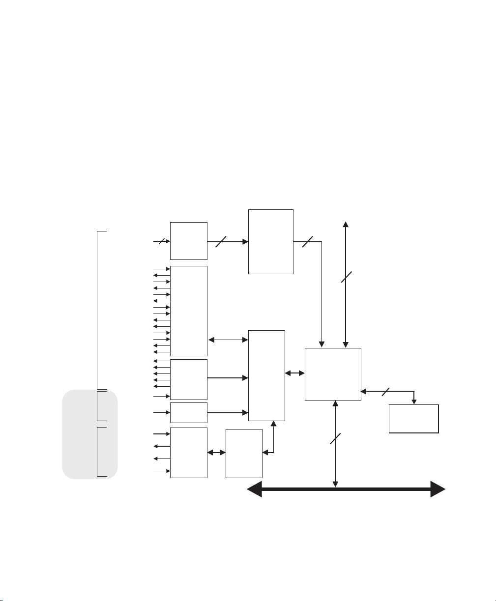
Matrox Meteor-II /Multi-Channel
Matrox Meteor-II /Multi-Channel is a monochrome and
component RGB analog frame grabber for standard and
non-standard video acquisition. Matrox Meteor-II
/Multi-Channel is available in a PCI or PC/104-Plus form factor ,
both of which can use a Matrox Meteor-II MJPEG module for
compression and d ec o m p re ssion of mono chrome a nd co lo r
images.
Page 12

12 Chapter 1: Introduction
VMChannel (not available
on CompactPCI and
PC/104-Plus)
Lowpass
Gain
4:1
MUX
White
Black
White
Black
White
Black
A/D
A/D
A/D
Sync
separator
Opto-
coupler
PSG
UART
24
LUT
3 256x8-bit
24
To DB-44
Connector
for PCI
form factor
To 30-pin
male,
connector
for
PC/104-Plus
form factor
* RS-422 version of these signals are available on the optional RS-422 connector.
This connector is only available on Matrox Meteor-II /Multi-Channel in a PCI form factor.
VID_IN1_1
VID_IN1_2
VID_IN2_1
VID_IN2_2
VID_IN3_1
VID_IN3_2
SYNC_IN
Trigger
Clk input
Clk output
Hsync
Vsync
Trigger
Exposure timer1
Exposure timer2
Not available on PC/104-Plus
form factor
Aux
RX
TX
/RTS
/CTS
2:1
MUX
2:1
MUX
2:1
MUX
2
{
2
TTL*
Drivers
&
Receivers
RS-232
Drivers
and
Receivers
filters/
24 32
VIA
32
MJPEG
Module
(optional)
64
SGRAM
(4 Mbytes)
Host 32-bit PCI bus
Acquisition features Matrox Meteor-II /Multi-Channel can acquire different types of
standard and non-standard monochrome and component RGB
video. The board features six softwar e-s electable inpu t
channels on which two component RGB or six monochrome
cameras can be attached. Matrox Meteor-II /Multi-Channel
supports acquisitio n from one camera at a time or simultaneous
acquisition from up to three g en-locked RS-170/CCIR cameras.
Matrox Meteor-II /Multi-Channel supports both single and
Page 13
Matrox Meteor-II boards 13
dual-tap configurations. It also accepts an external trigger, and
can operate in either asynchronous reset mode or next valid
frame/field mode.
The PCI form factor also includes an auxiliary power supply
input, which can be use d to draw aux iliar y pow e r from your
compute r to p ro vide powe r t o yo ur ca m e ra .
Matrox Meteor-II /Digital
Matrox Meteor-II /Digital is a digital frame grabber for
standard and non-standar d vide o acquis itio n. Th is board is
only available in a PCI form factor.
VMChannel
Hsync output
100-Pin
Connector
9-Pin Female
Trigger
Connector
9-Pin Male
RS-232
Connector
On separate bracket
Vsync output
Valid frames/line
Exposure timer1
Exposure timer2
Aux 1 output
Aux 2 output
Exposure timer1
Exposure timer2
Camera CTRL1
Camera CTRL2
Camera CTRL3
* Matrox Meteor-II is available with either RS-422 or LVDS support.
Data
Clk input
Clk output
Hsync input
Vsync input
Trigger
Aux 1 input
Aux 2 input
Trigger
Trigger
RX
/RTS
/CTS
32
RS-422/
LVDS*
Receiver
32
LUT
4 256x8-bit
or
2 4Kx16-bit
32
32
RS-422
/
LVDS*
Drivers
&
Receivers
TTL
Buffers
Opto-
coupler
TX
RS-232
Drivers
and
PSG
UART
VIA
32
64
SGRAM
(4 MB)
Receivers
Host 32-bit PCI bus
Page 14

14 Chapter 1: Introduction
Acquisition features Matrox Meteor-II /Digital can acquire digital video from
standard and non-standard cameras using the RS-422 or L VDS
differential sig ne d for mat. It suppo r ts image acq uisition from
genlocked came ra s in 4 x 8-bit, 2 x 16-bit, or 1 x 32-bit
configurations; the r efo r e, up to four cam e ras can be attac he d
to acquire four 8-bit or component RGB images. The board also
supports multi-tap grabs (u p to fo ur taps). I n addit ion, Matrox
Meteor-II /Digital accepts an external trigger, and can operate
in either asynchron o us reset mod e o r ne xt valid fr ame/field
mode.
Matrox Meteor-II /1394
Matrox Meteor-II /1394 is an IEEE 1394-to-PCI adapter board
that permits simplified, high-performance digital video capture
using a computer. This board is only available in a PCI form
factor.
6-pin IEEE-1394
Connector
6-pin IEEE-1394
Connector
6-pin IEEE-1394
Connector
Input
Input
Input
Physical
Layer
3.3V regulator
Link
Layer
32
Optional isolation
barrier
12V
input
Host 32-bit PCI bus
Acquisition features Matrox Meteor-II /1394 supports the transfer of monochrome
or color digita l vid eo from cam e r as which are compliant with
the IEEE 1394 Digital Camera Specification (DCS). Note,
Matrox Meteor-II /1394 has three input ports which can be used
for image acquisition.
Page 15
Matrox Meteor-II boards 15
The Meteor-II /1394 can also supply power from your computer
through the IEEE 1394 interface.
Matrox Meteor-II MJPEG module
Matrox Meteor-II MJPEG module is an optional board which
module supports lossy and lossl es s MJPEG (interla ced and
non-i nterlace d ) compress ion and deco mp re ssion of color and
monochrome video. There are two versions of the Matrox
Meteor-II MJPEG module: one is for use with the PCI and
CompactPCI for m fac tors, and the other is for use with the
PC/104-Plus form factor. The Matrox Meteor-II MJPEG module
is not supported by Matrox Meteo r-II /Digital and /1394.
Meteor-II
Grab Port
Interface
24
MJPEG Module
Pixel Data
Input/Output
Block
Data
8
Pixel
Interface
Color Space
Converter
JPEG
Processor
Strip Buffer
Memory
Host
Interface
Host
Interface
Code
Interface
16
SRAM
(64Kbytes)
8
8
Host
Interface
Progressive
MJPEG
24
Path
FPGA
JPEG
8
Processor
Interface
Memory
Port
64
VIA SGRAM
Interface Port
Page 16

16 Chapter 1: Introduction
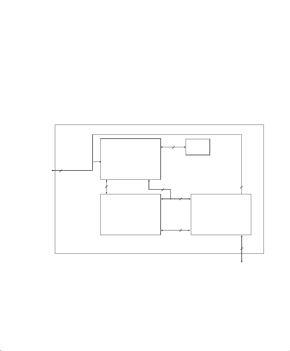
Data transfer
All versions of the Matrox Met eor-II board allow transfer of live
video to Host memory or off -board dis play memo ry. T o prevent
loss of data during long bus-access latencies found in heavily
loaded computer systems, the Matrox Meteor-II boards (except
Meteor-II /1394) feature 4 Mbytes of SGRAM for temporary
frame storage. All boards except Matrox Meteor-II /1394 are
also equipped with the Matrox Video Interface ASIC (VIA).
All PCI form factor boards (except the Meteor-II /1394) also
have a VMChannel interface (non-bus controller), which is used
to send data to o ther VM devices found on other Matrox imaging
boards (for example, Matrox Corona, Matrox Genesis main
1
board, or Matrox Genesis processor board)
.
Software
You can purchase one or more M atrox Imagin g so ft ware
products that support the Matrox Meteor-II board. These are
the Matrox Imaging Library (MIL) and its derivatives
(MIL-Lite, ActiveMIL-Lite, and Matrox Inspector). All Matrox
software is su p p orte d unde r Windows; co ns ult yo ur software
manual for supported Window s environments.
MIL MIL is a development library which provides an extensive list
of commands used to capture, process, analyze, transfer,
display, and archive images. Pr ocessing and analysis
operations include: spatial filtering operations, morphological
operations, measurements, blob analysis, optical character
recog nition ( OCR), p atter n match ing, matr ix/b ar code re ading ,
and cal ibrati on .
MIL-Lite MIL-Lite is a subs et of MIL. It inclu des al l the MIL commands
for image acquisitio n, transfer, display control, and archiving .
1. Since the Matrox Meteor-II boards cannot perform the
function of bus controller, they must be connected with at least
one board which is bus controll er capable , in order for VMChannel transfers to operate correctly.
Page 17

Matrox Meteor-II boards 17
ActiveMIL ActiveMIL is a set of ActiveX controls that are based on MIL .
ActiveMIL was designed for rapid application development
(RAD ) tools, suc h as Microso f t’ s Visual Ba sic. Ac tiveM I L is
included with MIL. (ActiveMIL-Lite is included with MIL-Lite.)
Inspector Inspector is an inter a ct ive Window s appli cation for image
capture, processing, analysis, and archiving.
MIL Developers can use Matrox Inspector as a prototyping tool
to quickly build proof-of-concept demonstrations for their
machine vision , image analysis, and medica l imaging system.
End users can use Matrox Inspect or to perform and automate
image enhancement and measurement tasks .
Intellicam Matrox Intellicam is an interactive Windows program that
allows fast camera interfacing and provides interactive access
to all the acquisition features of your Matrox board. For boards
that accept non-standard video sources, Matrox Intellicam also
has the ability to create custom digitizer configuration format
(DCF) files, which MIL and its d e riv ative s u se to interf ace to
specific non-standard video sources. Intellicam is included with
both MIL and MIL-Lite.
1
1. Matrox Meteor-II /Standa rd and /1394 only support
pre-defined DCF files.
Page 18

18 Chapter 1: Introduction
What you need to get started
To begin using Matrox Meteor-II, you need the following:
■ computer with a PCI bus and a Pentium processor or better .
■ Windows: Se e y o ur software pa ck ag e fo r sup p o rted
environments and RAM requirements.
Other useful
considerations
■ A computer with a relatively up-to-date PCI chipset, such as
the Intel 430HX, 430VX, 430TX, 440FX, 440LX, or 440BX for
full Matrox Meteor-II functionality. These chipsets are
recommended because they offer the required
sustaine d -throughp u t to H os t m emo ry.
■ A computer with an empty full-length 32-bit PCI expansion
slot (bus master capable).
■ A CD drive, and a hard disk or network drive on which to
install the Matrox Meteor-II software.
Page 19

Inspecting the Matrox Meteor-II package 19
Inspecting the Matrox Meteor-II package
Standard package
When you unpack your Matrox Met eor-II package, you s houl d
check its contents. Note that optional parts might or might not
be included, depend in g o n wh at yo u ord e red . If so met hing is
missing or damaged, contact your Matrox representative.
If you ordered Matrox Meteor-II, you should receive the
following items:
■ The Matrox Meteor-II /Standard, Matrox Meteor-II
/Multi-Channel, Matrox Meteor-II /Digital, or Matrox
Meteor-II /1394 board.
■ The M atrox Meteor-II Installation and Hardware Reference
manual (this d o cument).
■ A 4-pin power cable, included with Matrox Meteor-II
/Standard and /Multi-Channel (PCI form factor), and with
Matrox Meteor-II /1394.
■ A bracket with flat cables that attach to the trig ger an d
RS-232 input connectors, included wit h Matr ox Me teor-II
/Digital.
■ A 30-pin connector to interface with the video input
connector, included with Matrox Meteor-II /Standard and
/Multi-Channel for PC/104-Plus (stand-alone ve rs io n) .
Optional items
You might have also ordered one or more of the following:
■ MIL-32/CD, which includes ActiveMIL; MIL-LITE/32 CD,
which includes ActiveMIL-Lite; or Matrox
INSPECTOR-32/CD. MIL and MIL-Lite CDs include
Intellicam.
■ Matrox Meteor-II MJPEG module.
Page 20

20 Chapter 1: Introduction
■ DBHD44-TO-13BNC input cable with a high density 44-pin
connector and thirteen BNC connectors for the Matrox
Meteor-II /Standard (PCI and CompactPCI form factors). Si x
BNC-TO-SVHS (Y/C) adapt er ca bles are shipped with the
DBHD44-TO-13BNC cable.
■ DH44-TO-13BNC/ O inpu t cable with a high density 44-pin
connector , available for the Matrox Meteor-II / Standard. This
cable is required if you want to connect to special input and
output signals, such as synchronization signals, control
signals, and DC power output.
■ DBHD44-T O-8B N C input cable with a high den sity 44-pin
connector and eight BNC connectors for Meteor-II
/Multi-Channel (PCI form factor). Three BNC-TO-SVHS
(Y/C) adapter cables are shipped with the
DBHD44-TO-8BNC cable.
■ DH44-TO-8BNC/ O inpu t cable with a high densi ty 44-p in
connector, available for the Matrox Meteor-II
/Multi-Channel. This cable is required if you want to connect
to special input and output signals, such as synchronization
signals, control signals, and DC power output.
■ DBHD100-TO-OPEN cable for the 100-pin digital input
connector on the Matrox Meteor-II /Digital board.
❖Cables for Matrox Meteor-II /1394 are typically supplied with
the camera.
Handling components
The electronic circuits in your computer and the circuits on
Matrox Meteor-II are sensit ive to stati c electric ity and surge s.
Improper handling can seriously damage the circuits. Be sure
to follow thes e prec autions:
■ Drain static e lectr icit y fro m you r body by to uc hin g a m eta l
fixture (or ground) before you touch any electronic
component.
■ Avoid letting your clothing come in contact with the circuit
boards or components.
▲ Caution Before you add or remove devices from your computer, always
turn off the power to your computer and all peripherals
.
Page 21

Installation overview 21
Installation overview
The installation proce dur e consis t s of the foll owin g ste ps:
1. Complete the har dwar e instal latio n as de sc ribed in
Chapter 2. If you have any problems, refer to Appendix A.
2. Complete the software installation as described in
Chapter 3.
More information For information on using multiple Matrox Meteor-II boards,
refer to Chapter 4, and for in-depth hardware information, refer
to Chapter 5.
If you want technical information about Matrox Meteor-II,
including specifications and connector descriptions, and
pinouts, see Appendix B for Matrox Meteor-II /Standard,
Appendix C for Matrox Meteor -II /Multi -Channel, Appendi x D
for Matrox Meteor-II /Digital, and Appendix E for Matrox
Meteor-II /1394.
A history of the development of Matrox Meteor-II is available
in Appendix F.
Conventions When the term Matrox Meteor-II boards is used, it refers to all
versions of the board.
When the term Meteor-II for PC/104-Plus is used, it refers to
the stand-alone version (MET2+/4 or MET2-MC+/4). Another
version of Matrox Meteor-II is available pre-installed with
Matrox 4Sight, and technical information for this board is
available in the Matrox 4Sight User Guide.
When the term Host is used in this manual, it refers to your
computer.
This manual occasionally makes reference to a MIL-Lite
command. However, anything that can be accomplished with
MIL-Lite can also be accomplished with MIL, ActiveM I L,
ActiveMIL-Lite, or Matrox Inspector.
1. Most items can be accomplished with Matrox Inspector.
1
Page 22

22 Chapter 1: Introduction
Need help? Appendix A offe rs solutions to poten tial pro bl ems. If your
Matrox Meteor-II installation questions are not answered in
this manua l, c on tact y ou r loc al M atr ox re pre sen tat ive , Ma trox
Sales Office, or Matrox Imaging Custo mer Support Group (see
the Custom er Suppor t section at the bac k of this m anu al for
telephone numbers).
In the unlikely event of a failure, the warranty and Product
Assistance Request Form at the back of this manual outlines
return cond ition s a nd p rocedures.
Page 23

Chapter 2: Hardware installation
This chapter explains how to install the Matrox Meteor-II
hardware.
Page 24

24 Chapter 2: Hardware installation
Installing Matrox Meteor-II
Before you install your board, som e prec aut io nary m ea sure s
must be taken . Turn off power to the comp ute r and its
peripherals, and drain static electricity from your body (by
touching a metal part of the computer chassis). Next, follow the
steps to install you r board ac co rding to its form factor: PCI,
Compact P CI, or PC/1 0 4-Plus.
❖If you are not using Windows NT as your operating system,
your board must be installed before you install the software
(either MIL or one of its derivatives). If you are adding
another Matrox Meteor-II to your computer , you will have to
re-install your software after installin g yo ur board .
Installing Matrox Meteor-II for PCI
Use the following steps to install your Matrox Meteor-II board
for PCI:
1. Remove the cover from your computer using the
instructio ns from your com puter manua l.
2. Check that you have an empt y PCI (32-bit ) slot that can
accommodate the bo ard. If you do not have an em p ty slot,
remove a PCI board from your comput er to ma ke room for
your Matrox Meteor-II board and take note of the slot
number you choose.
Connectors of PCI slotsConnectors of PCI slots
or
Connectors of ISA slotsConnectors
of ISA slots
Page 25
Installing Matrox Meteor-II 25
▲ Caution Some compu ters ha ve a large, black -ridge d heat sink that
prevents board s from using most PCI board slots. Your
Matrox Meteor-II must not touch t his heat sink. Th erefore,
choose a slot where the board completely avoids it.
3. Connect the Matrox Met eor-II MJPEG modul e to the boar d
if required. See t he section, Installing th e Matrox Meteor-II
MJPEG module.
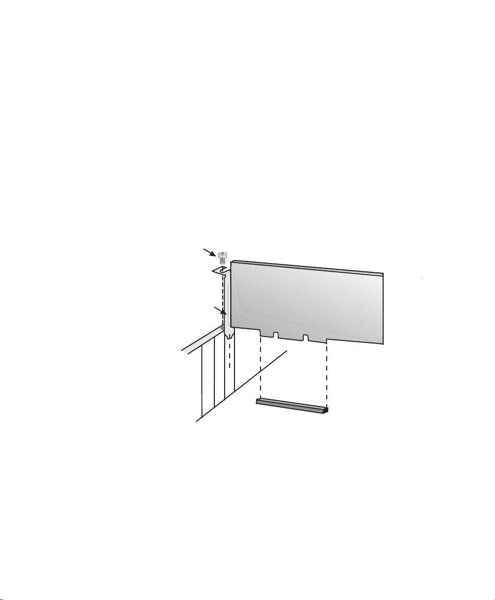
4. If present, remove the blank metal plate located at the back
of the selected slot. Keep the removed screw; you will need
it to fasten the Matrox Meteor-II board.
5. Carefully position Matrox Meteor-II in the selected PCI slot
as illustrated below. If you are using a tower computer,
orient the board to suit the board slots in your com pute r.
SCREW
METAL
PLATE
6. Once perfectly aligned with an empty slot, press the board
firmly but carefully into the connector.
7. Anchor the board by replacing the screw that you removed.
8. If you are installing the Matrox Mete or-II /Stand ard,
/Multi-Channel, or Meteor-II /1394, proceed to Step 9. If you
are installing the Matrox Meteor-II /D igital board, continue
with the following steps:
MATROX METEOR-II
PCI form factor
32-BIT PCI BOARD SLOT
Page 26
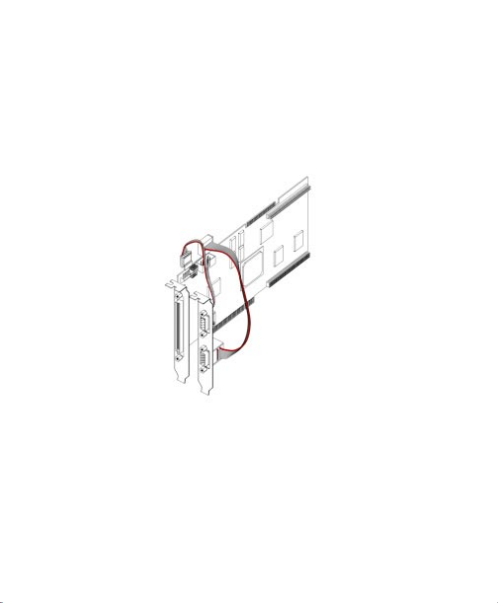
26 Chapter 2: Hardware installation
■ If present, remove the blank metal plate located at the
back of a slot next to the Matrox Meteor-II /Digital board;
do not discard this screw.
■ Install the brack et with the tr igger and RS-232 input
connectors and fasten it with the screw you just removed.
■ Connect the cables to the 4-p in tr igger connector and the
10-pin RS-232 connector on the Mat rox Meteor-II /Digital
board (see figure below).
9. Replace the cover of your computer.
10. Connect your vi deo source s. For det ails, see the Connecting
external devices section.
11. Turn on your computer.
Under Windows 98, when you boot your computer,
Windows’ Plug-and-Play system will detect a new PCI card
and you will be asked to assign a driver to it. At this point,
you should click on Cancel because the drive r will be
installed during the installa t i on of MIL or one of its
derivatives.
Page 27
Installing Matrox Meteor-II 27
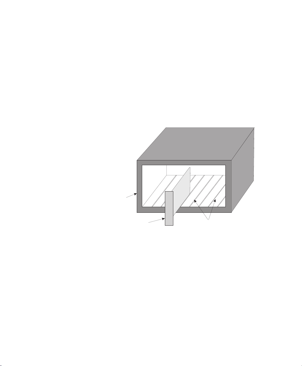
Installing Matrox Meteor-II for CompactPCI
Use the following steps to install your Matrox Meteor -II board
for CompactPCI (3U). Note that a 6U replacem ent brack et is
available.
1. Remove a plate on the subrack, exposing an empty slot.
2. Connect the Matrox Met eor-II MJPEG modul e to the boar d
if required. See t he section, Installing th e Matrox Meteor-II
MJPEG module.
3. Carefully position Matrox Meteor -II along one o f the guide
rails and slide the board towards the connector at the back.
Subrack
CompactPCI
Board
Guide slots
Page 28
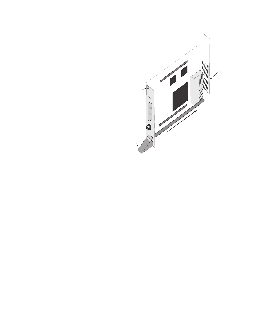
28 Chapter 2: Hardware installation
4. Press the board firmly but carefully into the connector.
Handle
Screw
Guide
Back plate
of subrack
CompactPCI
connector
5. When the board is in place, the han dle opens automatical ly ,
exposing a screw. Tighten both this screw, and the one at
the top of the bracket.
6. Connect your v ideo sour ces. For details, see the Connect ing
external devices section.
7. Turn on your computer.
Under Windows 98, when you boot your computer,
Windows’ Plug-and-Play system will detect a new PCI card
and you will be asked to assign a driver to it. At this point,
you should click on Cancel because the drive r will be
installed during the installa t i on of MIL or one of its
derivatives.
Page 29
Installing Matrox Meteor-II 29
Installing Matrox Meteor-II for PC/104-Plus
Use the following steps to install your Matrox Meteor -II board
for PC/104-Plus:
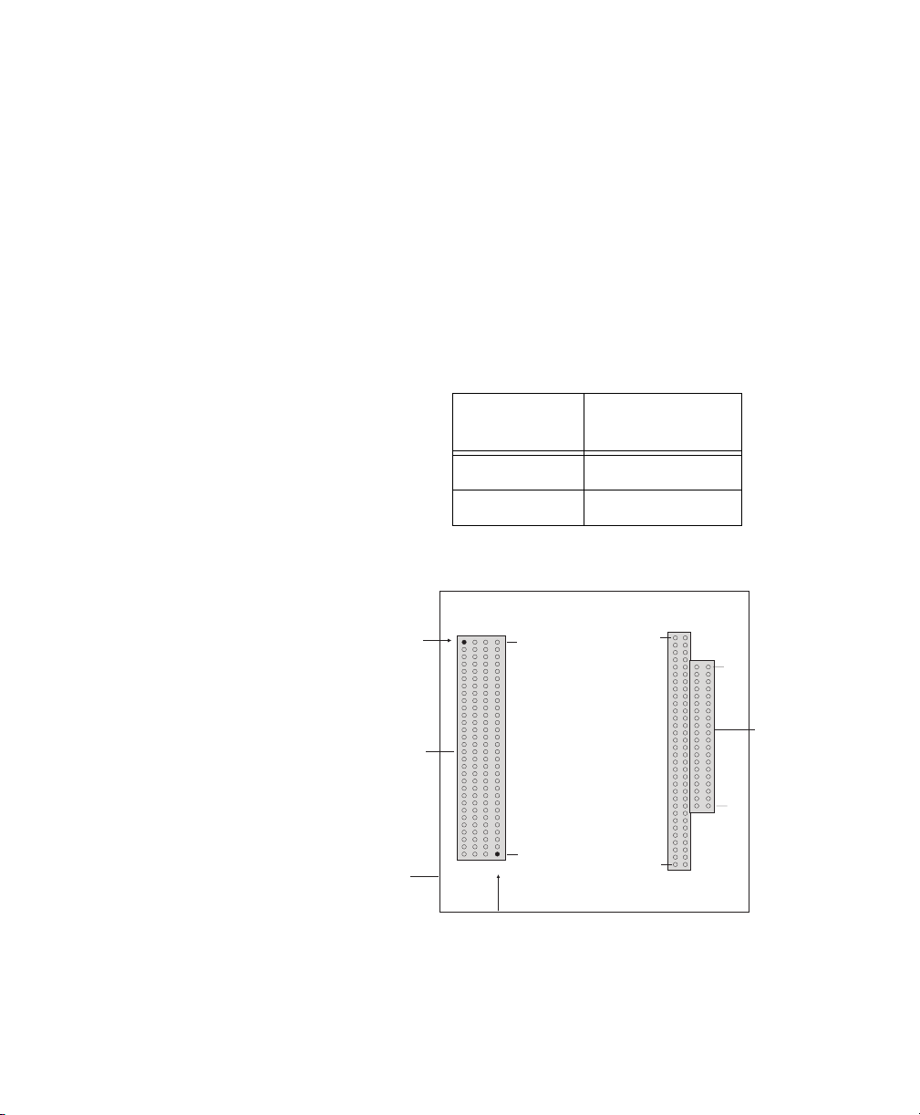
1. Matrox Meteor-II for PC/104-Plus can operate in either a
5V or 3.3V system. In some cases, a hole in the PC/104-Plus
(PCI) connector is filled, which prevents another
PC/104-Plus module from being stacked on top. To install
Matrox Meteor-II for PC/104-Plus in a system with a
specific signalling environment, a pin must be removed.
The table and diagram below indicate which pins to cut, and
their locations on the connector.
Signalling
environment
Pin to remove
on J3 connector
5V A1
3.3V D30
Remove pin D30
in a 3.3 V system
PC/104-
J3
30
Plus
J1
32
J2
19
(PCI)
0
CD
PC/104-
Plus
DCBA
1
1
BA
expansion site
Remove pin A1
ina5Vsystem
Top view
2. Connect the Matrox Met eor-II MJPEG modul e to the boar d
if required. See t he section, Installing th e Matrox Meteor-II
MJPEG module.
PC/104
(ISA)
Page 30
30 Chapter 2: Hardware installation
3. Check that you have an available PC/104-Plus connecto r on
the motherboard, or verify that your existing stack can
support another board.
4. If you have existing PC/104 boar ds in your com puter,
remove them and stack them on the PC/104-Plus board.
PC/104 boards must be stacked last.
5. Remove the anchoring screws fro m the stack; do not discard
them since you will need them to fasten the Matrox
Meteor-II board.
6. Carefully position Matrox Meteor-II over the connectors
and press the board firmly into place.
7. Replace the anchoring screws .
8. Set the rotary switch (next to the PC/104 (ISA) connector)
to 0 if installing the first stackable module, or another
appropriate setting if not the first. See the section, Multiple
board installation, in Chapter 4.
PC/104-
Plus
(PCI) connector
Expansion
module
connectors
PC/104
(ISA)connector
Motherboard
Rotary
switch
Video input
connector
9. Connect your v ideo sour ces. For details, see the Connect ing
external devices section.
Page 31

Installing the Matrox Meteor-II MJPEG module 31
10. Turn on your computer.
Under Windows 98, when you boot your computer,
Windows’ Plug-and-Play system will detect a new PCI card
and you will be asked to assign a driver to it. At this point,
you should click on Cancel becaus e th e drive r will be
installed during the installation of MIL or one of its
derivatives.
Installing the Matrox Meteor-II MJPEG module
Matrox Meteor-II MJPEG module is available in two form
factors: on e for use with P CI and CompactPCI fo rm factors, and
one for use with the PC/104-Plus form fa ct o r. The mo d ule is
supported on Matrox Meteor -II /S tandard an d /Mult i-Channel.
PCI and Co mpac tPCI
form fact ors
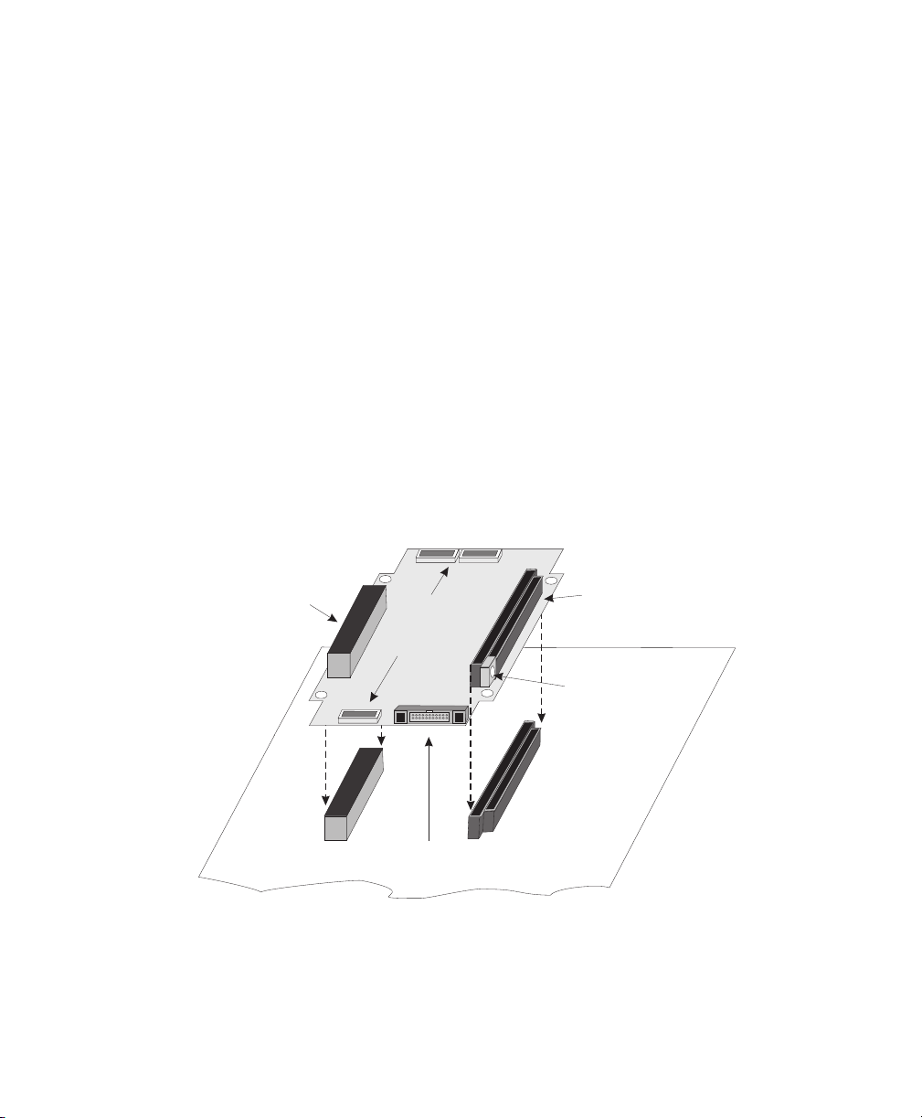
1. Position the boards such that the male connector on the
module is aligned with the female connector on the base
board and the female connector on the m odu le is aligne d
with the male connector of the base board.
MJPEG module
PCI connector
Meteor-II board
Page 32

32 Chapter 2: Hardware installation
2. Once the boards are perfectly aligned, press the module
firmly but caref u lly into th e con ne ct or s.
PC/104-Plus form factor On the PC/104-Plus form fact or, the expansion co nnectors are
located on the soldered side of the board. Follo w the steps below
to connect the Matrox Meteor-II MJPEG module to Matrox
1
Meteor-II for PC/104-Plus
MJPEG
Top pin
connector (male)
:
Top pin, spacer
and rivet at opposite side
of board
MJPEG
module
Rivet
Meteor-II
PC/104-Plus
Component
side
Spacer
PC/104(PCI)
connector
Plus
Expansion module
connector (female)
1. Align the connectors of the Matrox Meteor-II MJPEG
module with the e xp an sio n m od ule conn ec to rs on the
Matrox Meteor-II board.
2. Position the spacer bet wee n the boards over each small
hole, next to the MJP E G c onne c to rs.
3. Insert the rivet in to each hole from the s oldered s ide of the
Matrox Meteor-II MJPEG module, ensuring that it goes
through the s p acer.
4. Press the b oards to gether , s o the connec tors ar e snapped in
place.
5. Insert the top pin through the hole from the soldered side
of the Matrox Meteor-II MJPEG module to hold the rivet,
spacer, and boards in place.
PC/104
(ISA)
connector
1. The Matrox Meteor-II MJPEG module 896-00 rev. A has two
connectors and two pins. 896- 01 rev. A has three connecto rs and
five pins.
Page 33

Connecting external devices 33
Connecting external devices
All boards and f o rm f acto rs have th ei r own particulariti e s
regarding connectors and input devices. In this section, the
boards will be discuss ed in the followin g o rde r:
■ Matrox Meteor-II /Standard for PCI.
■ Matrox Meteor-II /Standard for CompactPCI.
■ Matrox Meteor-II /Multi-Channel for PCI.
■ Matrox Meteor-II /Standard and /Multi-Channel for
PC/104-Plus.
■ Matrox Meteor-II /Digital.
■ Matrox Meteor-II /1394.
Matrox Meteor-II /Standard for PCI
Matrox Meteor-II /Standard has six connectors, which are
indicated in the diagram below. Two of these connectors are
located on its bracket.The firs t fou r conn e ctor s liste d are
discussed in de tail in Ap p end ix B .
■ Video input connector. Used to receive analog video, as
well as send and receive synchronization signals and power.
■ BNC connector. Used to receive composite analog video.
■ Auxiliary power supply input. Used to route power from
your compute r thro ug h the Matrox Me teo r-II bo ard to your
camer a .
■ VMChannel connector. Used to send data to ano ther
Matrox board.
■ Expans io n modu l e in t erface
1
. Used to connect to the
optional Matrox Meteor-II MJPEG module (for image
compression and d e co m p re ssion).
1. Matrox Meteor -II /Standard boards 750-00 rev. A and 750-01
rev. A do not support the Matrox Meteor-II MJPEG module and
therefor e do not ha ve the se connectors.
Page 34

34 Chapter 2: Hardware installation
Video input
VMChannel
Auxiliary power supply
input
Connector 1 (male) for
expansion module
BNC
Connector 2 (female) for
expansion module
Connecting a video input to Meteor-II /Standard for P CI
or CompactPCI
You can connect vi deo sources to Matrox Meteor -II /Standard’ s
video input connector, using the optional DBHD44-TO-13BNC
cable. This cable has thir te en BNC connectors and a 44-pin
high-density D-Subminiature plug. The wires of the cable are
color-coded as follo ws. C onne c t your ca m eras ac co rdin gly.
Wires Signals Expected Input Form factor
RED (1) VID_IN1 Analog Video Input1 or Y1 PCI, CompactPCI
GREEN (2) VID_IN2 Analog Video Input2 or C1 PCI, CompactPCI
BLUE (3) VID_IN3 Analog Video Input3 or Y2 PCI, CompactPCI
BLACK (4) VID_IN4 Analog Video Input4 or C2 PCI, CompactPCI
WHITE (5) VID_IN5 Analog Video Input5 or C4 PCI, CompactPCI
YELLOW (6) VID_IN6 Analog Video Input6 or Y3 PCI, CompactPCI
PURPLE (7) VID_IN7 Analog Video Input7 or C3 PCI, CompactPCI
Page 35

Connecting external devices 35
Wires Signals Expected Input Form factor
BRO WN (8) VID_I N8 Analog Vid eo I n p u t8 or Y4 PC I
LIGHT BLUE (9) VID_IN9 Analog Video Input9 or Y5 PCI
ORANGE (10) VID_IN10 Analog Video Input10 or C5 PCI
PINK (11) VID_IN11 Analog Video Input11or Y6 PCI
LIGHT GREEN (12) VID_IN12 Analog Video Input12 or C6 PCI
GRAY (13) OPTOTRIG External trigger input* PCI, CompactPCI
*OPTOTRIG- is usually connected to the ground of the trigger
source.
Connect the supplied BNC-TO SVHS adaptor cables to the
DBHD44-TO-13BNC cable for Y/C input. The PCI form factor
supports up to six Y/C sources, and the CompactPCI form factor
supports up to three. The cable is color coded as follows:
Wires on
BNC-TO-SVHS
BLUE (Y) Red
GREEN (C) Green
Wires on DBHD44-TO-13BNC Description
(1)
(2)
Blue
(3)
Black
(4)
Ye llow
(6)
Purple
(7)
Brown
(8)
White
(5)
Light Blue
(9)
Orange
(10)
Pink
(11)
Light Green
(12)
Luminance
Chrominance
Connecting Matrox Meteor-II /Standard to other
boards
The VMChanne l inter f ace allo ws th e trans fer of da ta to oth er
Matrox boards. Insert a VMChannel backplane (available with
interconnect kits) acro ss the VM Channel interface to con nect
the boards. Note that when connecting multiple Matrox boards,
at least one of the boards must be bus-con troller cap able.
Matrox Meteor-II is not bus-master capable.
Page 36

36 Chapter 2: Hardware installation
Connecting Matrox Meteor-II /Standard to the auxiliary
power supply input
To use Matrox Meteor-II /Standard to power your camera:
1. Use the 4-pin power cable to connec t the auxil iary power
supply connector to the power supply in the computer.
2. Ensure that the jumper is across the appropriate Matrox
Meteor-II auxiliary power supply selection pins, for the
required voltage (5 V or 12 V). See Appendix B for a
diagram.
3. Use the DBHD44-TO-13BN C /O cab le to conne ct you r
camera’s video output and power supply input to the video
input connector. Note that the total current drawn by all
the cameras is lim ite d to 1.5 A, and the circu it use s an
auto-resettable fuse.
Matrox Meteor-II /Standard for CompactPCI
Matrox Meteor-II for CompactPCI has five connectors, which
are indicated in the diag ram below . T wo of these connector s are
located on its bracket, and are discussed in detail in Appendix
B.
■ Video input connector. Used to receive analog video, as
well as send and receive synchronization signals and power.
■ BNC connector. Used to receive composite analog video.
■ CompactPCI connector . Used to connect your board to the
PCI bus.
Page 37

Connecting external devices 37
■ Expans io n modu l e in t erface. Used to connect to the
optional Matrox Meteor-II MJPEG module (for image
compression and d e co m p re ssion).
Connector 2 (female) for
expansion module
CompactPCI connector
Video input
BNC
Connector 1 (male) for
expansion module
Connecting a video input (Co m pactPCI)
You can connect video sources to Mat rox Meteor -II / Standard’ s
video input connector CompactPCI form factor, using the
optional DBHD44-TO-13BNC cable. See the section,
Connecting a video input to Meteor-II /Standard for PCI or
CompactPCI.
Matrox Meteor-II /Multi-Channel for PCI
Matrox Meteor-II /Multi-Channel has six connec tors, which are
indicated in the diagram below. One of these connectors is
locat e d on its bracket. The first fou r co nnector s l isted are
discussed in de tail in Ap p end ix C .
■ Video input connector. Used to receive analog video, as
well as send and receive synchronization signals and power.
■ VMChannel connector. Used to send data to ano ther
Matrox board.
Page 38

38 Chapter 2: Hardware installation
■ Auxiliary power supply i nput. Used to route power from
your computer through the Matrox Meteor-II board to your
camera.
■ Expansio n module interface. Used to connect the optional
Matrox Meteor-II MJPEG module (for image compression
and dec o m pre ssion).
Auxiliary power supply input
Video input
VMChannel
Connector 1 (male) for
expansion module
Connector 2 (female) for
expansion module
Connecting a video inpu t to Meteor-II /Multi-Chann el
Connect video sources to Matrox Meteor-II /Multi-Channel’s
video input connector, using the optional DBHD44-TO-8BN C
cable. This cable has eight BNC connectors and a 44-pin
high-density D-Subminiature plug. The wires of the cable are
color-coded as follo ws:
Wires Signals Description
RED (1) VID1_IN1 A na l og Video Inpu t1, R
GREEN (2) VID1_IN2 Analog Video Input2, G
BLUE (3) VID1_IN3 Analog Video Input3, B
BLACK (4) SYNC_IN SYNC input
GREY (5) OPTOTRIG* External trigger input
WHITE (6) VID2_IN1 A n al og Video Inp ut4 , R
YELLOW (7) VID2_IN2 Analog Video Input5, G
PURPLE (8) VID2_IN3 Analog V ideo input6, B
Page 39

Connecting external devices 39
*OPTOTRIG- is usually connected to the ground of the trigger
source.
Connecting Matrox Meteor-II /Multi-Channel to other
boards
The VMChanne l inter f ace allo ws th e trans fer of da ta to oth er
Matrox boards. Insert a VMChannel backplane (available with
interconnect kits) acro ss the VM Channel interface to con nect
the boards. Note that when connecting multiple Matrox boards,
at least one of the boards you are connecting must be
bus-controller capable. Matrox Meteor-II is not bus-controller
capable.
Connecting Matrox Meteor-II /Multi-Channel to the
auxiliary power supply input
T o use Matrox Meteor-II /Multi-Channel to power your camera:
1. Use the 4-pin power cable to connect the auxiliary power
supply connector to the power supply in the computer.
2. Ensure that the jumper is across the appropriate Matrox
Meteor-II auxiliary power supply selection pins, for the
required voltage (5 V or 12 V). See Appendix B for a
diagram.
3. Use the DBHD44-T O-8BNC/ O cabl e to conne ct you r
camera’s vide o output and power supply input to the vid eo
input connector. Note that the total current drawn by all
the cameras is limited to 1.5 A, and the circuit uses an
auto-resettable fuse.
Matrox Meteor-II /Standard and /Multi-Channel for PC/104-Plus
Matrox Meteor-II /Standard and /Multi-Channel PC/104-Plus
form factor have seven connectors, which are indicated in the
diagram below.
■ Vide o input conn ector . A connect or used to rece ive analog
video, as well as send and rec e ive syn ch ro niza tio n sig nals
and power.
■ PC/104-Plus (PCI) connector. An interface connector to
send data across the P C I bus.
Page 40

40 Chapter 2: Hardware installation
■ PC/104 (ISA) connectors. Tw o interface connectors to send
data across the IS A bus.
■ Expansio n module int erface. Three connectors used to
attach to the optional Matrox Meteor -II MJPEG modul e (for
image co m p re ssion and d ec o m p re ssion); lo cated on th e
soldered side of the board.
PC/104(PCI)
Plus
Expansion
module
connectors
Video input
connector
PC/104
(ISA)
Connecting a video input to Matrox Meteor-II for
PC/104-Plus
Connect video sources to Matrox Meteor-II /Standard or
/Multi-Ch a nn el through their video input connector, a 30-pin
right-angle male connector. A standard cable for PC/104-Plus
form factor boards is not available from Matrox. You can use
the included mating connec tor , cr imp the ribbon cabl e to it and
attach your required connector to the other end of the ribbon
cable. Then, connect this custom cable to the video input
connector . See Appendices B and C for the pinouts, signals, and
ribbon cable information for the /Standard and /Multi-Channel,
respectively .
Matrox Meteor-II /Digital
Matrox Meteor-II /Digital has four connectors, which are
indicated in the diag ram below . Only one of these con nectors is
located on its brack et . All these con ne ctor s liste d be lo w are
discussed in det a il in Ap pen d ix D.
Page 41

Connecting external devices 41
■ Digital Video input. Used to receive digital video, as well
as send and receive sync hr onization signals.
■ Trigger input. A connecto r f o r d irect trigger inpu t in TTL
or opto-isolated format.
■ RS-232 input connector . Used as a standard RS-232 serial
port interface.
■ VMChannel. Used to se nd data to anoth e r Matro x boar d .
VMChannel
RS-232
Trigger input
Video input
Connecting a video input to Meteor-II /Digital
Connect video sources to Matrox Meteor-II /Digital’s video
input connector, using the optional DBHD100-TO-OPEN. This
cable can be cus tomiz ed to fit with the connect or on your v ideo
source. See Appendix D for the pinouts, signals, and mating
connector supplier.
Connecting Matrox Meteor-II /Digital to other boa rds
The VMChanne l inter f ace allo ws th e trans fer of da ta to oth er
Matrox boards. Insert a VMChannel backplane (available with
interconnect kits) acro ss the VM Channel interface to con nect
the boards. Note that when connecting multiple Matrox boards,
at least one of the boards you are connecting must be
bus-controller capable. Matrox Meteor-II is not bus-controller
capable.
Page 42

42 Chapter 2: Hardware installation
Matrox Meteor-II /1394
Matrox Meteor-II /1394 has four connectors, which are
indicated in the diagram below. Three of these connectors are
located on its bracket, and are discussed in detail in Appendix
E.
1394
ports
Auxiliary power
supply input
PCI connector
■ 1394 ports. Used to provide bi-d irectional serial
communication and power . Each I/O port features a standard
6 pin connector. See Appendix E for pinouts.
■ Auxiliary power supply i nput . Used to route power from
your computer through the Matrox Meteor-II /1394 board to
your came ra.
Connecting a device to Meteor-II /1394
Connect devices to Matrox Meteor-II /1394’s ports, using the
6-pin connectors. The cable for the Meteor-II /1394 is not
available from Matro x, but 1394 de vic e s, such as came ras ,
typically include a cable. See Appendix E for the pinouts,
signals, and mating connector supplier.
Page 43

Connecting external devices 43
Connecting Matrox Meteor-II /1394 to the a ux iliary
power supply input
To use Matrox Meteor-II /1394 to power your device:
1. Use the 4-pin power cable to connect the auxiliary power
supply connector to the power supply in the computer.
2. Connect your camera’s 1394 cable to one of the board’s ports.
Note that the total current dr awn by al l the cameras is
limited to 1.5A.
Page 44

44 Chapter 2: Hardware installation
Page 45

Chapter 3: Installing software
This chapter explains how to install the Matrox Meteor-II
software.
Page 46

46 Chapter 3: Installing software
Installing the software
To install any Matr ox ima ging software, place its CD in th e
appropriate drive; the setup.exe file will ru n auto m atically.
While installing the software, you will be asked to provide the
following information:
■ The drive and dire ct ory in which to install the sof tw a re.
■ The target operating system and compiler.
■ The type of Matrox hardware that is instal le d in your
computer.
❖ If you have an MGA board, check the MGA control panel to
ensure that yo u hav e th e lat es t disp lay d riv er installed. If
you do not have th e lates t, ins tall th e disp lay driver that is
on the CD.
Afte r ins t al l at i on, r e ad t he readme file(s) recommended by the
installation program.
Note about Matrox Intellicam
MIL-Lite uses digitizer configuration formats (DCFs) to
configure the camera interface on Mat rox di gitizers. The DCF
defines, amo ng oth e r thin gs, the vide o tim ing signals and the
video data format. Matrox Intellicam can b e used to crea te or
customize a DCF file , if the sup p lied fi les do no t inc lud e one
that matches your video source. Note that Matrox Meteor-II
/Standard and /1394 only accept sta ndar d input form ats ;
therefore, you can only use the predefined DCFs.
For more infor m ation abo u t M atrox In tellicam, refer to the
Matrox Intellicam User Guide.
Page 47

Chapter 4: Using multiple Matrox Meteor-II bo ards
This chapter explains how to use mul tiple Matrox Met eor-II
boards.
Page 48

48 Chapter 4: Using multiple Matrox Meteor-II boards
Using multiple Matrox Meteor-II boards
This section describes how to use multiple Matrox Meteor-II
boards. When a grab buffer is selected for display, grabbed
images are displayed on the VGA, live or pseudo-live,
depending on the operating computer and the position of the
window s. No te that th e PC I band width is limited, and hea vy
usage can affect the data transfer in computers using multiple
boards.
Multiple board installation
Instal ling multiple PCI
and Compa c tP CI
cards
Install each additional Matrox Meteor-II board, PCI and
CompactPCI form factors, as you installed the first board (refer
to Chapter 2). In other words, place each additional board in an
empty slot. For the PCI form factor, ensure that the installed
boards avoid the CPU heat sink.
Theoretically, you can have as many as 16 Matrox Meteor-II
PCI/CompactPCI boards installed in your compute r at one
time; this number is, however , li mited by the number of empty
slots in you r com p ute r and , fo r sim u ltaneous grab s, by the
available bandwidth of your computer (discussed later in this
chapter).
Using MIL- L ite, you have to allo cate a MI L system f or each
board and allo cate the resourc e s of ea ch M IL sy ste m .
Page 49

Multiple board installation 49
Insta lli ng m ult i p le
PC/104-Plus modules
Top screw
PCI connector
Host board
Y ou can stack a maximum of four PC/104-Plus modules, shown
in the diagram below. Note that if you have PC/104 modules in
your computer, they must be placed at the top of the stack.
ISA connectors
In addition, yo u must set the rotary swit ch of each PC/104-Plus
module to a unique setting in the stack. Settin g the ro tar y
switch dedicates a group of PCI signals to the module in the
stack: clock, request grant, ID select, and interrupt signals. It
is recommended that the first module installed (the module
closest to the Host CPU board) be configured to 0, the second
1, and so on. The table below shows the recommended switch
setting for each module, as well as the dedic ated s ign als.
Switch
position
Module
position
Interrupt Request
grant
0 or 4 1 Interrupt A 0 0
1 or 5 2 Interrupt B 1 1
2 or 6 3 Interrupt C 2 2
3 or 7 4 Interrupt D 2 3
ID
select
Page 50

50 Chapter 4: Using multiple Matrox Meteor-II boards
If you are installing an additional Matrox Meteor-II board on
Matrox 4Sight, the module already installed has the setting
fixed at 0; therefor e, th e setting o f the addit iona l module mus t
be at a setting other than 0 or 4.
Grabbing simult aneously from different boards
Y ou can simultaneously grab images from cameras attached to
different Matrox Meteor-II boards. To grab at exactly the same
time, the cameras must be genlock ed (synchr onized) and their
corresp o nding d igitiz e r config uration f o rm ats must be the
same. Note that thi s re str ict ion does no t ap ply to M atr o x
Meteor-II /1394
The number of cameras from which you can simultaneously
grab is determined by the PCI bandwidth available in your
computer.
.
Matrox Meteor-II
Matrox Meteor-II
Grabbing from two genlocked cameras
Page 51

Grabbing simultaneously from different boards 51
PCI bandwidth
requirements
Matrox Meteor-II /Standard, /Multi-Channel, and /Digital have
a low susceptibility to PCI bus latency due to 4 Mbytes of
SGRAM. In addition, sustained PCI-transfers to memory
require the use of a high performance PCI core-logic chipset,
such as the Intel 440LX or 440BX. If a high performance chipset
is used with a Matrox Meteor-II /Standard or /Multi-Channel
board, you should not have any PCI bandwidth problems when
grabbing up to two full-s ize d color image s sim u ltan eously
(using two boards). Howev er, grabbing more than two image s
simultaneously might result in PCI bandwidth problems.
As a reference point, grabbing one full-sized NTSC or PAL
image in real time will requir e a PCI band width of 35
Mbytes/sec or 42 Mbytes/sec, respectively, when transferring in
RGBX (32-bit) mode.
With the Matrox Meteor-II /Digit al board, you can experience
PCI bandwidth problems when grabbing from multiple
cameras that require a high bandwidth.
When grabbing from three or more Matrox Meteor-II boards
simultaneously , you will have to reduce the image size to avoid
reaching the upper limits of the overall available bandwidth.
Matrox Meteor-II /1394 Although Matrox Meteor-II /1394 supports simultaneous input
from multiple cameras, t here are iss ues wit h respec t to both
the PCI bus and the IEEE 1394 bus that restricts the actual
number. With respect to th e PC I bus, the available sustained
bandwidth is a factor, like other Matrox Meteor-II boards.
However, Matrox Meteor-II /1394 has a much smaller FIFO,
and is therefore more susceptible to long PC I bus late nc ie s.
With respect to the IEEE 1394 bus, Matrox Meteor-II /1394
OHCI-Lynx PCI-to-1394 Host controller is compatible with
serial IEEE 1394 bus data rates of 100, 200, or 400 Mbits per
second, and thes e rates are shared acro ss the three input por ts.
Once a time slice is allocated, the device is guaranteed to have
that time slice, and therefor e transfer data; however, the time
slices available will pose a lim itati on . In smaller systems, for
example with two or three cameras, there shoul d be enough
time slices to handle the load.
Page 52

52 Chapter 4: Using multiple Matrox Meteor-II boards
Page 53

Chapter 5: Matrox Meteor-II hardware reference
This chapter explains the architecture of the Matrox
Meteor-II hardware, as well as the available features and
modes.
Page 54

54 Chapter 5: Matrox Meteor-II hardware reference
Matrox Met eor-II har dware ref erence
This chapte r provide s in for m ation on the architecture,
operating modes, and supported features of the Matrox
Meteor-II boards.
For a summary of the information given in this chapter and
detailed spec if icat ions o f conne c tors an d pinouts, refer to
Appendices B, C, D, and E of this manual.
Matrox Meteor-II /Sta ndard grab section
The grab section of the Matrox Meteor -II /Standard board uses
a video decoder to capture composite RS-170, CCIR, NTSC, and
PAL, and component (Y/C) NTSC and PAL.
BNC Connector for
PCI and Compact
PCI form factors
To DB-44
Connector for
PCI and Compact
PCI form factors
To 30-pin male,
right-angle
connector for
PC/104-Plus
form factor
Not available on
CompactPCI
form factor
VID_IN1
VID_IN2
VID_IN3
VID_IN4
VID_IN5
VID_IN6
VID_IN7
VID_IN8
VID_IN9
VID_IN10
VID_IN11
VID_IN12
Trigger
Aux
RX
TX
/RTS
/CTS
Not available on PC/104-Plus
form factor
12:1
MUX
2
{
2
RS-232
drivers &
receivers
Low
Pass
Filter
Gain
Decoder
Opto-
coupler
UART
VMChannel (not available
on CompactPCI and
PC/104-Plus)
24
32
64
VIA
32
Host 32-bit PCI bus
MJPEG
Module
(optional)
SGRAM
(4 Mbytes)
.
Page 55

Matrox Meteor-II /Standard grab section 55
Performance The video timing p aram e ters supported by th e Matrox
Meteor-II /Standard board are as follows:
CCIR 601 sampling
rates
NTSC P AL NTSC P AL
Field rate (Hz) 60 50 60 50
Pixel/line (Pixels) 858 864 780 944
Active pixel/line (Pixels) 720 720 640 768
Active lines/frame (Lines) 480 580 480 580
Pixel rate (MHz) 13.5 13.5 12.27 14.75
ADC sampling rate (MHz) 27 27 24 .54 29.50
Line rate (KHz) 15.750 15.625 15.750 15.625
Square pixel sampling
rates
Input channels
Matrox Meteor-II /Standard for PCI and PC/104-Plus can
switch between up to t welve in dependent c omposit e or six Y/ C
video sources. Matrox Meteor -II /Standard for CompactPCI can
switch between s even indepen dent composite s ources, or up to
thre e Y /C video so urces.
Y ou can only acquire data from one channel at a time. Channels
can be selected with the MIL -Lit e comm and, MdigChannel().
Low-pass filter
The input low-pass filtering stage is us ed to lim it hig h
frequency noise an d aliasing effec ts at the input of the decoder.
The filter used on Matrox Meteor-II /Standard for PCI and
CompactPCI is a 4th o rde r But te rwor th filte r with a cu to ff
frequency of 8 MHZ. The filter used on Matrox Meteor-II
/Standard for PC/104-Plus is a single-order filter with a cutoff
frequency of 6 MHz.
Video decoder
A multi-standard video decoder is used to convert NTSC and
P AL analog video signals that are in composite (CVBS), or (Y/C)
formats to digitized component video. The decoder supports
Page 56

56 Chapter 5: Matrox Meteor-II hardware reference
RGB 8:8:8 (24-bit), RGB 5:6:5, YUV 4:2:2, and YUV 4:1:1 output
pixel formats. Note that YUV 4:2:2 output pixel formats are
grabbed as YUYV.
The video decoder on all form factors also features automatic
gain control (AGC ). Howe v er, you can disable this featur e
(MIL-Lite MdigControl() with
M_GRAB_AUTOMATIC_INPUT_GAIN set to M_DISABLE) and
adju st the ga in manu ally ( MdigControl() with
M_GRAB_INPUT_GAIN).
UART
Matrox Meteor-II /Standard for PCI and CompactPCI feature
a Universal Asynchronous Receiver/ Transmitter (UART) that
provides an RS-232 serial inte r face. For examp le, this allows
you to rem ot el y co ntr o l a cam e ra o r a m ot i on co ntrol unit, or
remotely communicate with a program logic controller (PLC).
The UART is programmed using the MIL-Lite command
MdigControl() with the
Trigger
Matrox Meteor-II /Standard accepts an external trigger input
which allows image acquisition to be synchronized to external
events. The trigger is synch ronous to the incoming video stream
and it is received thro ugh an opto-coupler that helps isolate the
rest of the circuitry from surges. Matrox Meteor-II /Standard
operates in next valid frame/field mode. When in thi s mode, the
digitizer waits for the next valid frame or field (as specified by
the DCF file) before commencing the grab. This trigger mode
functions in one of three ways:
M_UART... control type s.
■ Edge-triggered monoshot acquisition: The VIA (Video
Interface Asic) waits for the r ising/fal ling* edg e to capture a
singl e frame.
■ Edge-triggered continuous acquisition: The VIA waits
for the rising/falling* edge to start a continous grab.
■ Level- sensitiv e "continuou s" acquisi tion: The VIA grabs
continuously while the le vel of the tri gge r is high /low* .
* The polarity of the active and inactive levels of the trigger
signal are software program mable.
Page 57

Matrox Meteor-II /Standard grab section 57
Tr igger signals connected to the OPTOTRIG- and OPTOTRIG+
input pins, pass through an opto-coupler, a device that protects
the board from outside surges; OPTOTRIG- is usually
connected to the ground of the trigger source. The voltage
difference across OPTOTR IG+ and OP TO TR IG- must be
between 4.05 V an d 9.16 V for logic high, and between -5.0 V
and 0.8 V for logic low. Refer to Appendix B for the pinouts of
these signals on yo u r re spe ctive form facto r.
User bits
Matrox Meteor-II /Standard supports four auxiliary user bits
through the vid eo in put co nn e ctor: two input and two ou tp ut .
These are available for controllin g e xter nal eve nts suc h as a
strobe light. User bits are programmed using the MIL-Lite
command MdigControl().
Using the auxiliary power supply
Matrox Meteor-II /St andard can supply pow er to your c amera.
Use the 4-pin power cab le prov ided wi th your boa rd to c onnect
to the power supply of your computer. The operating voltage
can be set to either 5 V or 12 V, but the current drawn by all
cameras is limited to 1.5 A. The circuit uses an auto-resettable
fuse. For further information on connecting to the auxiliary
power supply connector, see the section, Connecting Matrox
Meteor-II /Standard to the auxiliary power supply input in
Chapter 2, and Appendix B. Note that this input is not available
on the CompactPCI and PC/104-Plus form factors.
Page 58

58 Chapter 5: Matrox Meteor-II hardware reference
Matrox Meteor-II /Multi-Channel grab section
The grab section of the Matrox Meteor -II /Multi-Channel board
captures monochrome or component-RGB video signals from
standard and non-standard cameras. Six monochrome or two
RGB cam e ras can be att ached.
VMChannel (not available
on CompactPCI and
PC/104-Plus)
Lowpass
Gain
4:1
MUX
White
Black
White
Black
White
Black
A/D
A/D
A/D
Sync
separator
Opto-
coupler
PSG
UART
24
LUT
3 256x8-bit
24
To DB-44
Connector
for PCI
form factor
To 30-pin
male,
connector
for
PC/104-Plus
form factor
* RS-422 version of these signals are available on the optional RS-422 connector.
This connector is only available on Matrox Meteor-II /Multi-Channel in a PCI form factor.
VID_IN1_1
VID_IN1_2
VID_IN2_1
VID_IN2_2
VID_IN3_1
VID_IN3_2
SYNC_IN
Trigger
Clk input
Clk output
Hsync
Vsync
Trigger
Exposure timer1
Exposure timer2
Not available on PC/104-Plus
form factor
Aux
RX
TX
/RTS
/CTS
2:1
MUX
2:1
MUX
2:1
MUX
2
{
2
TTL*
Drivers
&
Receivers
RS-232
Drivers
and
Receivers
filters/
24 32
VIA
32
MJPEG
Module
(optional)
64
SGRAM
(4 Mbytes)
Host 32-bit PCI bus
.
Page 59

Matrox Meteor-II /Multi-Channel grab section 59
Performance The video timing parameters (including those for progressive
scan) supported by the Matrox Meteor -II /Multi-Channel board
are as follows:
Max
Number of pixels / line (including sync and blanking) 4096*
Number of lines / frame (including sync and blanking) 4096*
Sampling rate (with external clock input, or in
line-locking mode)
Note that the maximum number of pixels per line that MIL
supports is:
Pixels
-------------- x N umbe r of L i n e s 4 M b y tes≤
Line
30 MSPS
Input channels
The Matrox Meteor-II /Multi-Channel has six independent
analog channels. These channels can support input from two
RGB or six monochrome cameras where the channels can be
selected with the MIL-L ite MdigChannel() command.
Low-pass filter
The input low-pass filtering stage is us ed to lim it hig h
frequency noi se and al iasing effects at the inp ut of the trip le
A/D converter. The filter used on Matrox Meteor-II
/Multi-Channel is a 4th order Butterworth filter with a cutoff
frequency of 10 MHz.
Gain
Matrox Meteor-II /Multi-Channel has adjustable gains. This
allows you to optimize the video input signal range.
Page 60

60 Chapter 5: Matrox Meteor-II hardware reference
You can change the ga in value using the MIL-L ite
MdigControl() command. The sup p orted gain facto r s a re as
follows:
Input video signal
amplitude
(excluding sync)
0.0 V up to 0.5 V 0.0 - 0.7 Vpp 4 M_G AIN 3
0.5 V up to 0.7 V 0.7 - 1.0 Vpp 2.8 (default) M_GAIN2
0.7 V up to 1.0 V 1.0 - 1.4 Vpp 2 M_G AIN 1
1.0 V up to 1.5 V 1.4 - 2.1 Vpp 1.3 M_GAIN0
1.5 V up to 2.0 V 2.1 - 2.9 Vpp 1 M_G AIN 4
T otal input vide o
signal amplit ude
(including sync)
Required
gain
setting
MIL
Triple A/D converter
A triple A/D converter with external reference generation and
sync slicing is used for component RGB digitization . The
converter can be ope rat ed at up to 30 MSP S.
In addition, the co nverter’s black and white re ference levels can
be adjusted individually . The black and white reference levels
can be adjusted between 0.6 V to 1.6 V and 1.6 V to 2.6 V
respective ly, in increments of 10.23 mV (98 distinct
adjustments).
Use the MIL-Lite MdigReference() comman d to set th e black
and white refer ence le vels.
PSG
The Programmable Synchronization Generator (PSG) is
responsi ble for m an a gin g all tim ing and synch ro nization
signals.
Phase-locked loop
The high-perfor mance, low-jit ter ph ase-lo cked loop (P LL) uses
frequenc y synthesis te chniques to gen e ra te the clock signal ,
when necessary.
The PLL can use the follo wing sources as a ref er ence:
Page 61

Matrox Meteor-II /Multi-Channel grab section 61
■ The on-board crystal oscillator.
■ The horizontal video synchronizati on s i gna l s u ppl i ed by t he
video source (line-locke d mode).
When in line-locked mo de and ac ce pting a composite vide o
signal, t he PLL can synchronize to either serrated or block
vertical sync hro n iz atio n signals.
■ The clock signal supplied b y the video sourc e (to genera te a
different clock).
When the input source supplies a sampling clock that does not
require adjust ment, t he PLL is bypas sed to a void addi ng ji tter
to the supplied clock.
General synchronization
Matrox Meteor-II /Multi-Channel can operate in either slave
or master mode.
Slave mode
Master mode
■ In slave mode, the video s ource provides the synchronizati on
information to Matrox Meteor-II /Multi-Channel. It can
accept one of the following synchronization schemes:
❐ The video source e nc ode s th e sy nc hronization si gnals on
the analog video signal prov ided to the bo ard.
❐ The video source supplies the horizont al and/ or vert i cal
synchron iza t i on signals separately in TTL format.
❐ The video source provides a composite synchronization
signal in TTL format, sepa rate from the anal og video.
■ Synchroniza tion inf o r m ation can be sent either wit h the
video data, or on a separate a nalo g synchron ization channel.
■ In master mode, Matrox Meteor-II /Multi-Channel
generates (using the PSG) the horizontal and/o r ve r tical
(TTL) sync hronization signals and suppl ies them to the video
source. This allows the video source to synchronize to the
board.
Page 62

62 Chapter 5: Matrox Meteor-II hardware reference
Trigger
Matrox Meteor-II /Multi-Channel accepts an external trigger
input which allows image acquisition to be synchronized to
external events. The boar d can operate in one of two modes, and
the selected mode is sp ecifie d by the DCF.
Matrox Meteor-II /Multi-Channel can operate in next valid
frame/field mode When in this mode, the dig itizer waits for the
next valid frame or field (as specified by the DCF file) before
commencing the grab. This trigger mode functions in one of
three ways:
■ Edge-triggered monoshot acquisition: The VIA (Video
Interface Asic) waits for the r ising/fal ling* edg e to capture a
singl e frame.
■ Edge-triggered continuous acquisition: The VIA waits
for the rising/falling* edge to start a continous grab.
■ Level- sensitiv e "continuou s" acquisi tion: The VIA grabs
continuously while the le vel of the tri gge r is high /low* .
* The polarity of the active and inactive levels of the trigger
signal are software program mable.
Matrox Meteor-II /Multi-Channel can also operate in
asynchronous reset mode. In this mode, the digitizer resets the
camera to begin a new frame when the trigger signal is received.
Direct TTL trigger Trigger signals can be received in TTL format directly through
the video-input connector on the PCI form f actor . The TTL level
signal must have a maximum am p litu d e of 5 V. A signal over
2 V is con sid ere d high while anything less than 0. 8 V is
considered low. The transition of 0.8 V to 2 V is considered to
be the rising edge.
The trigger signal’s pulse width must be greater than one pixel.
Y ou can determine the pulse width by taking the inverse of the
pixel freq ue nc y. For example, if the pixel frequency is
12.27 MHz, the minimum pulse width is 1/12.27 MHz
≈ 82
nanos ec o nd s.
Note the PC /10 4-Plus form factor does not support a TTL
trigger.
Page 63

Matrox Meteor-II /Multi-Channel grab section 63
opto-isolate d trig ge r Trigger signals connected to the OPTOTRIG- and OPTOTRIG+
input pins, pass through an opto-coupler, a device that protects
the board from outside surges; OPTOTRIG- is usually
connected to the ground of the trigger source. The voltage
difference across OPTOTR IG+ and OP TO TR IG- must be
between 4.05 V an d 9.16 V for logic high, and between -5.0 V
and 0.8 V for logic low. Refer to Appendix C for the pinouts of
these signals on your board.
UART
Matrox Meteor-II /Multi-Channel features a Universal
Asynchronous Receiver/Transmit ter (UART) t ha t provide s a n
RS-232 serial interface. For exam ple , this allo ws you to
remotely control a camera or a motion control unit, or remotely
communicate with a program logic controller (PLC). The UART
is programmed using the MIL-Lite command MdigControl()
with the
Note that the UART is not present on the Meteor-II
/Multi-Channel for PC/104-Plus.
M_UART... cont ro l ty p e s.
Lookup table (LUT)
Matrox Meteor-II /Multi-Channel has three 256x8-bit input
lookup tables (LUTs), allowing indep end e nt re-m app in g of
three 8-bit input strea m s.
The LUTs on the Matrox Meteor-II /Multi-Channel for PCI
support RGB 8:8:8 (24-bit) output pixel formats. The LUTs on
the PC/104-Plus form factor support RGB 8:8:8, RGB 5:6:5, and
RGB 5:5:5 output pixel formats. LUTs are programmed using
the MIL-Lite command, MdigLut().
User bits
Meteor-II /Multi-Channel supports four auxiliary TTL user bits
through the vid eo in put co nn e ctor: two input and two ou tp ut .
These are available for controllin g e xter nal eve nts suc h as a
strobe light or PLC. User bits are programmed using the
MIL-Lite command MdigControl().
Page 64

64 Chapter 5: Matrox Meteor-II hardware reference
Using the auxiliary power supply
Matrox Meteor-II /Multi-Channel can supply power to your
camera. Use the 4-pin power cable provided with yo ur board to
connect to the power supply of your computer. The operating
voltage can be set to either 5 V or 12 V , b u t t he c ur re nt drawn
by all cameras is limited to 1. 5 A. Th e circuit use s an
auto-resettable fuse. For further informatio n on c onnecting to
the auxiliary power supply connector, see the section,
Connecting Matrox Meteor-II /Multi-Channel to the auxiliary
power supply input in Chapter 2, and Appendix B. Note that
this input is not available on the CompactPCI and PC/104-Plus
form factors.
Matrox Meteor-II /Digital grab section
The grab section of the Matrox Meteor-II /Digital board
captures video from standard and non-standard digital
cameras. It support s component RGB, as well as monochrome
acquisiti on, in single o r m ulti -t ap configurations. Up to fou r
genlocked cameras can be attached to acquire four 8-bit or two
16-bit inpu ts.
The board is available in two versions to suppor t eit her th e
RS-422 or the LVDS interface, but is available for the PCI form
factor only.
Page 65

Hsync output
100-Pin
Connector
9-Pin Female
Trigger
Connector
9-Pin Male
RS-232
Connector
On separate bracket
Vsync output
Valid frames/line
Exposure timer1
Exposure timer2
Aux 1 output
Aux 2 output
Exposure timer1
Exposure timer2
Camera CTRL1
Camera CTRL2
Camera CTRL3
Data
Clk input
Clk output
Hsync input
Vsync input
Trigger
Aux 1 input
Aux 2 input
Trigger
Trigger
RX
/RTS
/CTS
Matrox Meteor-II /Digital grab section 65
VMChannel
UART
LUT
4 256x8-bit
or
2 4Kx16-bit
PSG
32
VIA
32
32
64
SGRAM
(4 MB)
32
RS-422/
LVDS*
32
Receiver
RS-422
/
LVDS*
Drivers
&
Receivers
TTL
Buffers
Opto-
coupler
TX
RS-232
Drivers
and
Receivers
* Matrox Meteor-II is available with either RS-422 or LVDS support.
.
Host 32-bit PCI bus
Performance The video timing p aram e ters supported by th e Matrox
Meteor-II /Digital board are as follows:
Number of pixels / line (includin g syn c and blan k ing) 65536
Number of lines / frame (including sync an d blank ing) 65536
Sampling rate (LVDS, or LVD S with ex tern al clock inp u t) 40 Mhz
Sampling rate (RS-422 or RS-422 with external clock input) 25 Mhz
Max
Page 66

66 Chapter 5: Matrox Meteor-II hardware reference
UART
Matrox Meteor-II /Digital features a Universal Asynchronous
Receiver/Transmitter (UART) that provides an RS-232 serial
interface. Fo r exam ple , this allo ws remote camera
configuration, a motion control unit, or of a program logic
controller (PLC). The UART is progra mmed using the MIL-Lite
function, MdigControl() with the
Lookup table (LUT)
The Matrox Meteor-II /Digital bo ard has four 256x8-bi t
programmable lookup tables. The LUTs on Matrox Meteor-II
/Digital can be operated as four 8-bit lookup tables, two 10-bit
lookup tables, or two 12-bit lookup tables.
PSG
The Programmable Synchronization Generator (PSG) is
responsi ble for m an a gin g all tim ing and synch ro nization
signals.
Control signals
The following is a short description of the control signals on the
Matrox Meteor-II /Digital int erface. Note that depending on the
version of your board , the signals will be in RS-422 or LVDS
format. It i s indicated w hen other si g nal s such as TTL signals
are al so supported.
M_UART... cont ro l t yp es.
Synchronization The interface can receive and/or supply the HSYNC and
VSYNC signals. The VIA receives the synchronization signals
from the PSG or from an external source.
Valid The VIA also receives a VALID signal that can either be
generated by the PSG or an external source. When received by
PSG, it can indicate valid pixels o n a line b y line basis. When
received from an external source, it can indicate valid pixels on
a pixel by pixel basis.
Clock The interface of the Matrox Meteor-II /Digital boar d can receive
and supply a cloc k, sim ul tane o u sly.
Page 67

Matrox Meteor-II /Digital grab section 67
Auxi liary Seven general p urpo se aux iliar y signals are suppo rted : four
RS-422 or L VDS user signals (two input, two output), and three
TTL output si gnals. These are avai lable for control ling external
devices, such as a stro be ligh t. User signals are program me d
using the MIL-Lite command MdigControl().
Exposure Two timers in the P SG can generate two expo su re signals
simultaneously. There are available in TTL or RS-422/LVDS
formats. Exposures are progra m me d usin g the MIL -Lite
function, MdigControl().
Trigger Three trigger inputs are routed dir ectly to th e PSG; the
interfac e su pports TTL and RS-422/LVDS trigger input. In
addition, a trigger sign al connected to the OPTO TRI G - and
OPTOTRI G+ input pins, passe s thr o ugh an opto-coup le r, a
device that protects the board from outside surges; OPTOTRIGis usually connec te d to the gr ound o f the trigger source. This
external trigger in put allo ws imag e acqui sition to be
synchronized with external events. The board can operate in
one of two mode s, and the sele cted mode is spec ified by the DCF.
Matrox Meteor-II /Digital can operate in next valid frame/field
mode When in this mode, the digitizer waits for the next valid
frame or field (as specified by the DCF file) before comme ncing
the grab. This trigger mode functi ons in one of three ways:
■ Edge-triggered monosh ot acquisition: The VIA (Video
Interface Asic) waits for th e risin g/fallin g* edge t o capture a
single frame.
■ Edge-triggered continuous acquisition: The VIA waits
for the rising/falling* edge to start a continous grab.
■ Level-sensitive "continuous" acquisition: The VIA grabs
continuously while the level of the tr igge r is high /low*.
* The polarity of the acti ve and inac tive le ve ls o f the trigg er
signal are software progra m m able.
Matrox Meteor-II /Digital can also operate in asynchronous
reset mode. In this mod e, the d igitizer resets the cam era to
begin a new frame wh e n the trigger signal is receive d .
Page 68

68 Chapter 5: Matrox Meteor-II hardware reference
Matrox Meteor-II /1394
Matrox Meteor-II /1394 is capable of acting as bus manager
(cycle master), isochronou s resou rc e manage r, and node
controller ("root" ). The cy cle master trigge rs the data signal at
125-microsecond intervals. The isochronous resource manager
is responsible for reserving, distributing, and managing the two
modes of data stre am s (iso c hro nous and async hr on o us) alo ng
the available bandwid t h. The roo t cont ro ller c an control all
peripheral devices connected (up to a maximum of 62).
The 1394 bus transfers real-time (isochronous) data streams
through a four-layered architecture, two of which are
implem e n t e d in ha rd ware: the Ph ysi c a l L a ye r and the Link
Layer.
6-pin IEEE-1394
Connector
6-pin IEEE-1394
Connector
6-pin IEEE-1394
Connector
Input
Input
Input
Physical
Layer
3.3V regulator
Link
Layer
32
Optional isolation
barrier
Host 32-bit PCI bus
12V
input
Inputs Matrox Meteor-II /1394 has three IEEE 1394 input ports to
which 1394 devices can be attached, as long as the configuration
of devices complies with the IEEE 1394 tree topology. Serial
data bus rates of 100, 200, or 400 Mbits per second are shared
across the thr ee po rts . MIL- Li te can be used to gr ab from
monoch rom e o r color di gi tal came ra s that are com p liant with
the IEEE 1394 Digital Camera Specification (DCS). Note that
YUV 4:2:2 data is grabbed in UYVY form at.
Page 69

Matrox Meteor-II /1394 69
Physical Layer The physical layer (PH Y) is par t of a bi-direc tio nal in te rfac e
between the link layer (Link) and the actual IEEE 1394 serial
bus. The physical layer acts as a conve rter, reformatting the
commands and digital data it receives, so that the data can be
transmitted over the serial bus. The PHY monitors the line
conditions to determining conn e cti on status, for initializatio n
and arbitration, and for packet reception and transmission. The
physical layer supports data transmission rates of up to 400
Mbits per second.
Link Layer The link layer (Link) is the second co mp one nt in the
bi-directional interfac e betw een the ph ysic al laye r (PHY) and
PCI bus. The Link is a PCI-to-1394 Host contro ller and is
compliant with both PCI and 1394 OHCI spe cificatio n s. The
link layer supports both asynchronous and isochronous data
transfer between nodes. When transmitting packets, the Link
must se nd a requ est t o the PHY, which contro ls t he di recti on of
transmission between the two layers. The link layer also
controls the transfer speed between itself and the PHY, and
supports data transfers of 100, 200, or 400 Mbits per second. In
addition, th e Link is c apable of tran sferring a cac heline of data
at 132 MBytes per second over the PCI bus after connecting to
the memory controller on the Host. In order to overcome high
or long PCI latency, the link layer also provides deep FIFOs.
Galva nic is olation
barrier (optional)
The optional galvanic isolation barri er is ol ates the Matrox
Meteor-II /1394’s ground from that of the 1394 netwo r k. For
example, 1394 network could consist of several PCs, or other
devices such as a digital televisi on or digital VCR. If each device
in the network has a different ground, a potential difference is
created across them; this situation is called a ground loop, and
can eventually lead to loss of data, or even damage to system
components. If a power surg e occurs, the c ircuit tr ies to grou nd
excess power, but the Matrox Meteor-II /1394 would be
protected because its ground is isolated from the rest of the
network.
Page 70

70 Chapter 5: Matrox Meteor-II hardware reference
Data interfaces
Video Interface ASIC
With the exception of Meteor-II /1394, all Meteor-II boards have
a VIA, which acts mainly as a bridge to the PCI bus. The VIA
is capable of high-speed image transfers to Host memory or
other PC I devices across the PCI bus. It uses 4 Mbyte s o f
SGRAM (on-boar d mem ory ) to store data until the PCI bus
becomes available. On the PCI form factor, the VIA also
supports image transfers across the VMChannel to one or more
Matrox imaging boards for accelerated image pro ces sing or
display.
Simultaneous data
streams
General features The VIA is capable of pla ne separ ation of i mage input on two,
Matrox VIA can manage up to two simultaneous data streams.
For example , it ca n grab into SGRAM, a nd co ncurren t ly
transfer data over the VMChannel or PCI buses.
three, or four 8-bit or 16-bit components (for ex ample , RGB
packed to RGB planar). This mechanism is also used to merge
line segments of monochrome multi-tap cameras.
PCI interface
Matrox Meteor-II has a 32-bit PCI bus interface, capable of a
peak transfer rate of 132 Mbytes/sec.
The VIA’s PCI inter face The VIA’s PCI interface is 32-bits wide and operates at 33 MHz.
It allows all VIA resources to be accessed through a 128-Mbyte
memory region, mappable anywhere in the 4-Gbyte PCI
address spac e .
In addition, the PCI in te rface support various p lane a n d pi xe l
transfer modes by using some of the VMChannel logic.
Consequently, VMChannel and PCI transfers cannot be
performed simultaneously.
Read pre-fetch and write posting buffers are integrated to
optimiz e Ho st acc e ss.
Page 71

Matrox Me teor-II MJPEG Modul e 71
VMChannel
Matrox Meteor-II provides a 32-bit non-bus controller
VMChannel interface for a secondary or additional high-speed
connection between on-board and external devices. On a
68-wire ribbon cable system, the VMChannel runs at 25 MHz
for 100 Mbytes/sec peak transfer rates. On a backplane system,
it runs at 33 MH z for 132 Mbytes/sec pe ak trans fer rates.
The VMChannel is only available on the PCI form factor of
Matrox Meteor-II/Standard, /Multi-Channel, and /Digital.
Matrox Meteor-II MJPEG Module
The optional Matrox Meteor-II MJPEG module performs
real-time lossy and lossless MJPEG (interlaced and
non-i nterlace d ) compress ion and deco mp re ssion of color and
monochrome video. There are two versions of the Matrox
Meteor-II MJPEG module available: PCI and PC/104-Plus.
Matrox Meteor-II for CompactPCI boards can use the PCI
version of the Matrox Meteor-II MJPEG module. The Matrox
Meteor-II MJPEG module is not supported by Matrox Meteo r-II
/Digital and Matrox Meteor-II /1394.
Page 72

72 Chapter 5: Matrox Meteor-II hardware reference
Meteor-II
Grab Port
Interface
24
MJPEG Module
Pixel Data
Input/Output
Block
Data
8
Pixel
Interface
Color Space
Converter
JPEG
Processor
Strip Buffer
Memory
Host
Interface
Host
Interface
Code
Interface
16
8
(64Kbytes)
8
8
SRAM
Host
Interface
JPEG
Processor
Interface
MJPEG
FPGA
Progressive
Path
Memory
VIA SGRAM
Interface Port
24
Port
64
The Matro x Me te o r-I I MJ PEG module sup por ts lo ssy
compression of RGB 8:8:8 and YUV 4:2:2 standard video, in
continuous mode. The module also supports lossy and lossless
compre ssion of 8-b it m o no chrome i m ag e s.
❖10- and 12-bit lossless compression is supported on th e
PCI/CompactPCI version only.
Color Spac e C onverter The Color Space Converter has two functions. During
compress io n, it conve rt s the inc omi ng d ata f o r the JP EG
processor; the data i s reformatted fr om raster format in to 8 x 8
pixel blocks and then passed bac k to the J PEG proce ssor. The
Color Space Converter’s second function is to convert RGB data
into YUV format in order to reduce the processing time and the
amount of da ta f o r compress ion.
During decompression, th e 8 x 8 pi xel blocks are refo rm a tted
into raster format, a nd in the case of RGB dat a, the Color Space
Converter reconverts the compressed YUV data into RGB data.
Page 73

Matrox Me teor-II MJPEG Modul e 73
JPEG Processor During compression, the JPEG Processor receives the 8 x 8
pixel blocks and compresses them according the JPEG
standard. Both los sy and lo ssless formats ar e sup por te d.
During decompression, the JPEG Processor decompresses the
data, and transfers the 8 x 8 pixel blocks to the Colo r Spac e
Converter.
MJPEG FPGA T he MJPEG FPGA control s the direc t io n of compres sed and
decompresse d d ata and ge nerates contro l signals on the
module. It implements a bus handshake with the VIA on the
baseboard to ac cess the SGRAM. The SGRAM on the baseboard
is used to store the compressed data.
Encoding M JP EG During MJPEG (interlaced) compression, the baseboard grabs
a field of data. This data enter s the mod u le throu gh th e
Meteor-II grab port, and passes through the Color Space
Converter, the JPEG Processor, and finally exits the module to
the Host throug h the m emory port on the M JP E G FPGA ch ip .
Host
Encoding JP EG During JPEG (non-interlaced) compression, the baseboard
grabs an entire frame of data. This data enters the module
through the memory port on the MJPEG FPGA chip and passes
through the Color Space Converter. From there, JPEG
compress io n foll ow s the sam e pa th as MJPEG compr e ssion.
Compressing an archived video stream is supported under
JPEG com p re ssion.
Host
Page 74

74 Chapter 5: Matrox Meteor-II hardware reference
Decoding During decompression, the data enters through the memory
port on the MJPEG FPGA chip, and passes thro ugh the JPEG
processor , the Color Space Converter, and finally exits through
the Matrox Meteor-II grab port.
Host
❖Due to a hardware limitation, the MJPEG m o dule on the
Matrox Meteor-II /Standard cannot decompress JPEG
(non-interlaced) compres se d data; deco mpress i on of JPEG
data will be performed by the Host.
Page 75

Appendix A: Troubleshooting
This appendix gives suggestions to help you resolve
potential problems. I f your problem is not addressed her e,
contact your local Matrox representative, Matrox Sales
Office, or the Matrox Imaging Customer Support Group.
Page 76

76 Appendix A: Troubleshooting
Troubleshooting
If you have problems using your Matrox Meteor-II board, please
try the followin g:
■ Check for disconnected power cords.
■ Read the Common problems and solutions section in this
chapter.
If your problem is not address ed in th is chapter or if the
solutions suggested don’t work for you, contact your local
Matrox representative, Matrox Sales Office, or the Matrox
Imaging Customer Support Group.
Common problems and solutions
Installation Problems
☛ PC/104-Plus module cannot be stacked
■ If you cannot stack your PC/104-Plus module, check the
connectors of the board in the s tac k and determine if any of
the PCI connector’s holes are filled. If this is the case, cut the
corresponding pins on your boar d. See the section, Installing
Matrox Meteor-II for PC/104-Plus in Chapte r 2.
■ If your com p ute r ha s P C/104 modul es , you m u st re - stac k
them so the PC/104 m od ules are o n top of PC/104-Plus
module s. Be sur e to rese t the rotary switches for your new
stack configuratio n .
☛ Board service fails to start
This could happen due to the following two reasons:
■ The MIL Matrox Meteor-II drivers are not installed corr ectly .
❐ When the board fa ils to start under Windows NT, your
computer will prompt you to go to the Event Viewer utility
to identify the dev ice that was unable to start. Click the
Devices icon in the Control Panel. In the Devic es dialog
box, find your Matrox frame grabber in the presented list.
Page 77

Common problems and solutions 77
If the Startup column reads Automatic, and the Status
column is blank, the driver can be started by clicking the
Start button.
❐ When the board fails to start under Windows 98, the driver
is probably not installed. Check for a Meteor-II device in
the Wi ndows Dev ice Manage r property s heet. This sheet
can be accessed using the System utility in the Control
Panel. If you do not see a Meteor-II device under Matro x
Imagin g Adapters, you will have to reinstall the driver.
❐ When the board fails to start under Windows 2000, th e
driver might not have started. Right-click on My
Computer, and select Manage from the presented menu.
Select Computer in the Com puter Manage m e nt d ialo g
box. Select the View Hidden Devices comman d . Select
Device Manager in the left pane. Select Non- Plug and
Play Drivers in the right pane. Double-click on the name
of your Matrox driver. Select the Driver tab in the
presented dial og box. Cl ick the Start button. If you do not
see a Meteor-II dev ice under Matrox Imaging Adapters,
you will have to reinstall the driver.
If the above solution for your operating system does not work,
try the following.
❐ The driver also might not start due to too much or
insufficient allo cat ion of DMA memory. To address the
problem of DMA memory, uninstall and reinstall MIL, and
specify the correct DMA setting.
■ There is a conflict in the BIOS Setup program. This problem
generally occur s when there is a PCI memory ma pping error
or when there is a PCI-IRQ routing error. To resolve this
problem with the PCI form factor, first try to swap boards
from one PCI slot to another; for the PC/104-Plus, change the
rotary switch settings. If the problem still persists, upgrade
your BIOS.
Page 78

78 Appendix A: Troubleshooting
If the above solution does not work, try the following to
determine if the re is an I RQ co n fl ict.
❐ Under Window s N T, go to W in dows NT Diag no st i c s
❐ Under Windows 98, right-click on My Computer, and
❐ Under Windows 2000, right-click on My Computer, and
☛ Not enough memory to allocate buffer un der
Windows NT 4.0
property sheet (found under Start Programs
Administrati ve T ool s (Common). Under the Resources
tab, check for devices that are sharing an IRQ with your
Matrox frame grabber .
select Computer from the presented menu. Go to View
Resources, selecting the Interrupt request (IRQ)
checkbox. Check for devices that are sharing an IRQ with
your Matrox frame grabber.
select Manage from the presented menu. Select
Computer in the Computer Management dialog box.
Selec t System Inf ormati o n\ Hardware Re source s\ I RQ.
Check for devices that are sharing an IRQ with your
Matrox frame grabber .
This is the me ssag e th at yo u will rece ive if you try to allo cat e
a grab buffer that is greater than the amount of DMA memory
specified durin g so ftwar e insta llatio n. Th is p roble m can b e
addressed by increasing the amount of DMA memory on your
computer. Uninstall and reinstall MIL and specify the
appropriate amount of DMA memory. Alternatively , re-allocate
DMA memory using the included milconfig.exe utility.
Grabbing Problems
☛ Opto-isolated tri gger pulse is not connected
When usin g the o p to -iso late d trig ge r, both OPTOTRI G- and
OPTOTRIG+ signals must be connected. OPTOTR IG- is
usually con ne cted to the ground of th e tr igg er so urc e.
Page 79

Common problems and solutions 79
☛ IRQ conflicts
In general, PCI devic es can share an interrupt line (IRQ).
However, sometimes this migh t no t be po ssib l e; for ex am pl e,
complex PC I devices, or bus maste r de vic es sho uld not share
an IRQ. The types of difficulties that you might run into are as
follows:
■ IRQ conflict un d er Windows NT 4.0
In the event that your Matrox imag ing board(s) cannot share
an IRQ line with othe r de vic es , alloc ate a diffe rent IRQ to
each device in the IRQ Configuration Setup section of the
BIOS Setup Program, if possible (accessible on bootup).
■ IRQ conflict un d er Windows 98
To resolve this problem with the PCI and CompactPCI form
factors, either re-assign a different IRQ line to the PCI slot
in which the Matrox Meteor-II board is installed or change
the resource settings in the Windows’ Device Manager
property page. This page can be accessed using the System
utility in the Control Panel.
To resolve this problem wit h the PC/ 104 -P lus form factor,
change the rotary switch se ttin gs.
❖Note that PCI devices cannot share interrupt lines with EISA
or ISA devices .
Other possible solutions to the above problems:
■ Move the Matrox Meteor-II board to another (free) PCI slot.
■ Swap Matrox Meteor-II with another board.
Problems during applicatio n development
☛ Computer ‘hangs’ or produces unwanted results while a n
applic at ion is runnin g
Sometimes, an EISA or ISA d evic e might attempt to use the
same interrupt, registers, or memory space as PCI boards, and
this causes a conflict. Check for an inter ru pt, me m o ry, or
register co nf lict:
Page 80

80 Appendix A: Troubleshooting
■ Unde r Windows NT, go to Win do w s NT Di ag no s tics
property sheet (found under Start Programs
Administrative Tools (Common). Under th e Re so urces
tab, check for devices that are sharing an IRQ with your
Matrox frame grabber.
■ Under Window s 98, ri ght -click on My Computer, and select
Computer from the presented menu. Go to View Resources,
selecting the Interrupt request (IRQ) checkbox. Check for
devices that are shar ing an IR Q with your Mat rox frame
grabber.
■ Under Windows 2000, right-cli ck on My Computer, and
select Manage from the presented menu. S elect Co m puter
in the Computer Management dialog box. Select System
Information\ Hardware Resources\ IRQ. Check for devices
that are sharing an IRQ with you r Matr ox frame grabbe r.
Contacting Matrox
Before con tac ting you r local Matrox repre sentative, Matrox
Sales Office, or th e Matrox Ima ging Customer Support G roup,
you will need the foll ow ing information :
■ A description of what happened;
■ Computer (motherboard) make and model number,
environment, and peripherals (especially boards sharing the
computer with your Matrox Meteor-II);
■ Your board’s serial number (printed on the bar code label),
and revision number.
Use the Product Assist a nce Request Form at the back of this
manu a l to re cord the ne cessary in fo rmation .
Page 81

Appendix B: Technical information Matrox Meteor-II /Standard
This appendix contains information that might be useful
when installing your Matrox Meteor-II /Standard board.
Page 82

82 Appendix B: Technical information Matrox Meteor-II /Standard
Technical information
This appendix contains information that might be useful when
installing your Matrox Meteor-II /Standard board.
General information
■ Operati ng sy ste m : See yo ur software man ual for supp o rted
versions of Windows.
■ System requir emen ts: A compu ter with a PCI bus and a
Pentium processor or equivalent.
Some olde r systems use a core lo gic chipse t (i nt er fa ces PCI
with Host memory) that has limited throughput capabilities.
Matrox Meteor-II /Standard might not be able to attain full
functionality on such systems. We recommend systems with
newer PCI chipsets, such as the Intel 430HX, 430VX, 430TX,
440FX, 440LX, or 440BX. If you need more specific
information regarding potential problems, refer to Appendix
A - Troubleshooting.
■ Technical features:
❐ PCI and PC/104-Plus form factors feature twelve software
selectable channels, which support up to twelve inputs in
either monochrome RS-170/CCIR or composite NTSC/P AL
form ats, o r up to six Y/C video inputs in NTSC /PAL
formats.
❐ CompactPCI form factor features seven soft ware selectable
channels, which sup po rt up to se ve n inputs in either
monochrome RS-170/CCIR or composite NTSC/PAL
formats, or up to three Y/C video inpu ts NTS C/PAL
formats.
❐ Accepts an extern al trig ge r in pu t, w hic h can operate in
next valid frame/field mode.
❐ Features programmable or automa t i c gain contr ol .
❐ Features 4 MBytes of SGRAM.
❐ Features Strap-selectable 5 or 12 V DC output (PCI form
factor only).
Page 83

Board input and output connectors 83
❐ Features an RS-232 port.
❐ Features 32-bit bus-controller VMChannel interface.
Board input and output connectors
PCI form factor Matrox Meteor-II /Standard PCI form factor has six interface
connectors: a VMChannel, an auxiliar y power supp ly inp u t, a
1
video input, two connectors
BNC connector.
VMChannel
Auxiliary power supply
input
Video input
for an expansion module, and a
Connector 1 (male) for
expansion module
BNC
Connector 2 (female) for
expansion module
1. Revisions 0 and 1 of the Matrox Mete or-II /Standard board do
not have an expansi on si te and therefore do not have these connectors.
Page 84

84 Appendix B: Technical information Matrox Meteor-II /Standard
CompactPCI form
factor
Matrox Meteor-II /Standard CompactPCI form factor has five
interface connector s : a video input, a BNC, two connect ors for
an expansion module, and a CompactPCI connector.
Connector 2 (female) for
expansion module
CompactPCI connector
Video input
BNC
Connector 1 (male) for
expansion module
PC/104-Plus form factor Matrox Meteor-II for the PC/104 -Plus form f actor (stan d alone
version) has five interface connectors: a video input, two
connectors for the expansion module, a PC/104-Plus (PCI), and
a PC/104 (ISA) connector .
PC/104-
Plus
(PCI)
Expansion
module
connectors
Video input
connector
PC/104
(ISA)
Page 85

Board input and output connectors 85
Video input connector on M atrox Meteor-II for PCI and CompactPCI
pin 30
pin 16
pin 44
pin 31
pin 15
pin 1
The video input conn e ctor is a high den sit y DB -44 f ema le
connector on the P CI and CompactPCI form fac tors. Its pi nout
is shown below. Note the Form Factor column specifies the
board which supports that particular pinout.
Pin Signal I/O Description Form
Factor
1 DC_OUT O +12 V/ +5 V Power Supply. PCI
2 VID_IN12 I Analog Video Input #12 or C6 PCI
3-5 GND - Ground. PCI, Compa c tPCI
6 CTS I Clear To Send (RS-232). PCI, CompactPCI
8 USER(2)_OUT O Auxiliary User Output #2 PCI, CompactPCI
9 USER(2)_IN I Auxiliary User Input #2 PCI, CompactPCI
11 VID_IN5 I Analog Video Input #5 or C4 PCI, CompactPCI
13 VID_IN3 I Analog Video Input #3 or Y2 PCI, CompactPCI
14 GND - Ground. PCI, CompactPCI
15 VID_IN1 I Analog Video Input #1 or Y1 PCI, CompactPCI
16 DC_OUT O +12 V/ +5 V Power Supply. PCI
17-18 GND - Ground. PCI, CompactPCI
19 VID_IN10 I Analog Video Input #10 or C5 PCI
Page 86

86 Appendix B: Technical information Matrox Meteor-II /Standard
Pin Signal I/O Description Form
Factor
20 VID_IN 9 I Anal og Video I n put #9 or Y5 PCI
21 RT S O Request To Send (RS-232). PCI, CompactPCI
22 RX I Receive (RS-2 3 2). PCI, CompactPCI
23 VID_IN 8 I Anal og Video I n put #8 or Y4 PCI
24 USER(1)_OUT O Auxiliary User Output #1 PCI, CompactPCI
25-31 GND - Ground. PCI, CompactPCI
33 VID_IN 11 I Analog Video Input #11 or Y6 PCI
34 OPTOTRIG- I Opto-Isolated trigger negative input. PCI, CompactPCI
35 OPTOTRIG+ I Opto-Isolated trigger positive input. PCI, CompactPCI
36 TX O Transmit (RS-232). PCI, CompactPCI
39 USER(1)_IN I Auxiliary User Input #1 PCI, CompactPCI
40 VID_IN 7 I Anal og Video I n put #7 or C3 PCI, C ompactPCI
41 VID_IN 6 I Anal og Video I n put #6 or Y3 PCI, CompactPCI
42 GN D - Ground. PCI, Compa c tPCI
43 VID_IN 4 I Anal og Video I n put #4 or C2 PCI, C ompactPCI
44 VID_IN 2 I Anal og Video I n put #2 or C1 PCI, C ompactPCI
7, 10,
12, 32,
37, 38
Not used PCI, CompactPCI
Use Matrox cable DBHD 44-T O-13BN C to inte r face with this
connector. The cable has thirteen BNC connectors, and a
high-density 44-pin D-Subminiature male connector . This cable
allows you to attach up to twe lve analog video sourc es , and a
trigger inpu t.
An open-ended ve r sion of this cabl e, the DH 44-T O-13BNC / O,
is also available that can be used to access signals in addition
to those described abo ve. Parts for cables can be purchased
from:
■ Ma nufacturer: NorComp Interconnect Devices
■ Connector & shell: HDT44P
Page 87

Board input and output connectors 87
1
2
29
30
Video input connector on Matrox Meteor-II /Standard for PC/104-Plus
The video input connector on the Meteor-II /Standard for
PC/104-Plus is located on the top side of the board. Its pinout
is as follows:
Pin Signal I /O Description
2 VID_IN1 I Analog Video Inp ut #1 or Y1
4 VID_IN2 I Analog Video Inp ut #2 or C1
6 VID_IN3 I Analog Video Inp ut #3 or Y2
8 VID_IN4 I Analog Video Inp ut #4 or C2
10 VID_IN5 I Analog Video Inp ut# 5 or C4
12 VID_IN6 I Analog Video Inp ut #6 or Y3
14 VID_IN7 I Analog Video Inp ut #7 or C3
15 USER(2)_IN I Auxiliary User Input #2
16 USER(1)_IN I Auxiliary User Input #1
17 USER(2)_OUT O Auxiliary User Output #2
18 USER(1)_OUT O Auxiliary User Output #1
20 VID_IN8 I Analog Video Inp ut #8 or Y4
22 VID_IN9 I Analog Video Inp ut #9 or Y5
23 OP TOTRIG- I Opto-Isola ted trigger n e gative input
24 OP TOTRIG+ I O pto-Isolated trig ger pos itive inpu t
26 VID_IN10 I Analog Video Input #10 or C5
28 VID_IN11 I Analog Video Input #11 or Y6
30 VID_IN12 I Analog Video Input #12 or C6
1, 3, 5, 7, 9,
11, 13, 19,
21, 25, 27,
29
GND Ground
Page 88

88 Appendix B: Technical information Matrox Meteor-II /Standard
The mating connector included with the board is a 30-pin male,
0.050 pitch right an gle co nnector. Parts for cables ca n be
purchased from:
■ Manufacturer: Fujitsu
■ Connector FCN-217J030-G/O
This connector interfaces with a ribbon cable, 0.025 inch pitch
(0.635 mm), AWG #30 (solid wire).
VMChannel interface connector
The VMChannel interface allows Matrox Meteor-II /Standard
to share data with any Matrox im ag ing board that has a
VMChannel interface capable of performing the bus controller
function. A VMC han ne l backp lan e (ava ilable with the
GEN-BUS/... interconnect kits) must be inserted across the
VMChannel interfaces of the boards.
Note the VMChannel is not supported on the CompactPCI and
PC/104-Plus form factors.
pin 34
pin 68
top view of board
(component side)
pin 1
pin 35
side view of board
pin 68
The followin g table p rovide s th e pinou t of th e VMChannel
interface:
Pin Signal Pin Signal
SAN
1
(component side)
35
pin 35
N/C*
Page 89

Board input and output connectors 89
Pin Signal Pin Signal
2
3
4
5
6
7
8
9
10
11
12
13
14
15
16
N/C*
BSN[0]
DGND
CONTROL
N/C
CLK
VMSENSE
MASK0
DGND
DATA[1]
DATA[2]
DGND
DATA[5]
DATA[6]
DGND
36
37
38
39
40
41
42
43
44
45
46
47
48
49
50
DGND
BSN[1]
SNRDYN
DGND
DGND
DGND
DGND
MASK1
DATA[0]
DGND
DATA[3]
DATA[4]
DGND
DATA[7]
DATA[8]
17
18
19
20
21
22
23
24
25
26
DATA[9]
DATA[10]
DGND
DATA[13]
DATA[14]
DGND
DATA[17]
DATA[18]
DGND
DATA[21]
51
52
53
54
55
56
57
58
59
60
DGND
DATA[11]
DATA[12]
DGND
DATA[15]
DATA[16]
DGND
DATA[19]
DATA[20]
DGND
Page 90

90 Appendix B: Technical information Matrox Meteor-II /Standard
2
1
Pin Signal Pin Signal
27
28
29
30
31
32
33
34
DATA[22]
DGND
DATA[25]
DATA[26]
DGND
DATA[29]
DATA[30]
DGND
61
62
63
64
65
66
67
68
DATA[23]
DATA[24]
DGND
DATA[27]
DATA[28]
DGND
DATA[31]
SBN
* N/C = Not connecte d . This mean s that th e pin mig ht be
defined as part of the VMChannel interface standard but it is
not used on the Matrox Meteor-II /Standard board.
BNC connector
The BNC connector provides a single composite input to the
Matrox Meteor-II /Standard board . Its pin assignments are as
follows:
■ 1: composite 1 or VID_IN1.
■ 2 (SHELL): ground.
You can use a standard video cable (available from your local
electronic store) to interface with this connector.
Auxiliary power supply input
4
3
2
1
The auxiliary power supply input connector is a standard 4-pin
male connector that routes power from the computer to a
camera (via the DB-44). Use the 4-pin power cable provided
with your boar d to connect to the power supp ly of your
computer. The operating current is 1.5 A with an
auto-resettable fuse. Note that this input is not available on the
CompactPCI and PC/104-Plus form factors.
Page 91

Board input and output connectors 91
The pinout of the auxiliary power supply input connector is as
follows:
Pin Description
1 +12 V
2Ground
3Ground
4+5 V
For customers building their own cable, the part number of the
camera supply connector is as follows:
■ Manufacturer: VEN
■ Connector: 2490-04PRT
Auxiliary power supply selection
The following diagram shows the location of the auxiliary power
supply selec tio n and their corre sp o nd in g pi n numbers:
+5V
pin 1
+12V
pin 2 pin 3
Page 92

92 Appendix B: Technical information Matrox Meteor-II /Standard
Jumper
As shown in the table below , pl ace the jumper across pins 1 and
2 for a +5 V supply output and across pins 2 and 3 for a +12 V
supply output.
Pin Description
1-2 +5 V (default)
123
pin pin pin
Side view
2-3 +12 V
By default, auxiliary power supp ly is str ap ped fo r +5 V (pins
1-2).
Specifications
Electrical
Form Factor Operating Voltage an d curre n t Power
Consumption
5 V ±5% -5 V ±5% 3.3 V ±5% 12 V ±10% -12 V ±10%
a
PCI and
1.25 A n/a n/a 250 mA 50 mA 9.85 W
CompactPCI
PC/104-Plus 100 mA 25 mA 1.1 A 150 mA n/a 6.06 W
a. This number represents the tota l power consumption of the Matrox Meteor-II board only. It
does not include the power consu mption of a Matrox Meteor-II MJPEG module, or of a
camera which draws current through the auxiliary power supply input.
Environmental
■ Min./max. amb ient oper atin g te mp eratu re: 0°C - 55° C.
■ Min./max. storage temperature: -40° C - 75° C.
■ Max. altitud e for operatio n : 3000 mete rs .
■ Max. altitud e for transpo r t: 1200 0 meter s.
■ Operating hu mid ity : 20 - 80% relative humidity
(non-condensing).
Page 93

Appendix C: Technical information Matr ox Met eor-II /Multi-Channel
This appendix contains information that might be useful
when installing your Matrox Meteor-II /Multi-Channel
board.
Page 94

94 Appendix C: Technical information Matrox Meteor-II /Multi-Channel
Technical information
This appendix contains information that might be useful when
installing your Matrox Meteor-II /Multi-Channel board.
Global information
■ Operati ng sy ste m : See yo ur software man ual for supp o rted
versions of Windows.
■ System requir emen ts: A compu ter with a PCI bus and a
Pentium processor or equivalent.
Some olde r systems use a core lo gic chipse t (i nt er fa ces PCI
with Host memory) that has limited throughput capabilities.
Matrox Meteor-II might not be able to attain full
functionality on such systems. We recommend systems with
newer PCI chipsets, such as the Intel 430HX, 430VX, 430TX,
440FX, 440LX, or 440BX. If you need more specific
information regarding potential problems, refer to Appendix
A - Troubleshooting.
Technical features:
❐ Features six software selectable channels, which support
six monochrome or two component RGB vide o inputs. Any
of these channels can serve as the sync channel; however ,
there is also a separat e sy nc chan ne l.
❐ Supports both s i ngl e an d dual-tap (channel) mo nochr ome
cameras.
❐ Accepts an exte rnal trigger input and can opera t e in nex t
valid frame/field mode or asynchronous reset mode.
❐ Features three 256 8-bit input look up table s th at can
output RGB 8:8:8, YUV 5:5:5, or YUV 5:6:5.
❐ Features four Mbytes of SGRAM.
❐ Features programmable reference levels.
❐ Features various input gain settings.
❐ Features an RS-232 port.
Page 95

❐ Features strap-selectable 5 or 12 V DC output (PCI form
factor only).
❐ Features 32-bit bus-controlle r VM Channel inter f ace.
Board input and output connectors
The Matrox Meteor-II /Multi-Channel PCI for m factor has six
interface connectors: a VMChannel, an auxiliary power supply
input, a video input, two connectors for an expansion module.
Auxiliary power supply input
Video input
Board input and output connectors 95
VMChannel
Connector 1 (male) for
expansion module
Connector 2 (female) for
expansion module
Page 96

96 Appendix C: Technical information Matrox Meteor-II /Multi-Channel
pin 1
pin 31
pin 16
pin 44
pin 15
pin 30
PC/104-Plus form factor Matrox Meteor-II for the PC/104 -Plus form f actor (stan d alone
version) has five interface connectors: video input, two
connecto rs for the expansion modu le, a PC/104-Plus (PCI)
connector, and PC/104 (ISA) connector.
PC/104-
Plus
(PCI)
Expansion
module
connectors
Video input
connector
PC/104
(ISA)
Video input connector on the PCI form factor
The video inpu t connector is a high density DB -44 female
connector on the PCI form factor. Its pinout is as follows:
Pin Signal Description
15 VID1_IN1 RED Analog Video Input ( Cha n nel 1) .
44 VID1_IN2 GREEN Analog Video Input (Channel 1).
13 VID1_IN3 BLUE Analog Vide o Input (Channel 1).
43 SYNC_IN Analog Video Input (SYNC).
11 VID2_IN1 RED Analog Video Input (Channel 2) .
41 VID2_IN2 GREEN Analog Video Input (Channel 2).
40 VID2_IN3 BLUE Analog Video Input ( Ch a nn el 2) .
35 OPTOTRIG+ Opto-Isol a te d tri g ger positive in put .
34 OPTOTRIG- Opto-Isolated trigger negative input.
20 TRIGGER Non-Protecte d TTL tri g ger input.
19 CLK _IN_TTL Clock input (TT L).
33 CLK_OUT_TTL Clock outp ut ( TTL) .
32 VSYNC_TTL Vsync input or output (TTL).
Page 97

Board input and output connectors 97
Pin Signal Description
2 HSYNC_T TL Hsy nc inp ut or output (T TL ).
38 EXP(1) Exposure #1 output (TTL).
23 EXP ( 2) E xposu re #2 ou tput (T TL).
36 TX Transmit (RS-232).
22 RX Receive (RS-232).
6 C TS CTS (RS-232).
21 RTS RTS (RS-232).
39 USER1IN+ Auxiliary User Input #1 (positive).
12 USER1IN- Auxiliary User Input #1 (negative).
9 USER2 IN+ Auxiliary User Input #2 (positive).
10 USER2IN- Auxiliary User Input #2 (negative).
24 USER1OUT Auxiliary User Output #1 (TTL).
8 USER2 OUT Auxiliary User Output #2 (TTL).
1, 16 DC POWER +12 V OR +5 V Power Supply.
7, 37 NC Not connected on
3-5, 14,
17-18,
25-31,42
GND Ground.
METEOR-II/Multi-Channel.
Use Matrox cable DBHD44-TO-8BNC to interface with this
connector. It has eight BNC connectors and a high-density
44-pin D-Subminiature male connector. This cable allows you
to attach up to six video sources, an analog sync, and a trigger
input.
An open-ended version of this ca ble, th e DH44-TO-8BNC/O, is
also available and can be custom ized to access sig nals in
addition to those described above. For customers planning to
build their own cable , p arts can be purchased fro m :
■ Manufacturer: NorComp Interconnect Devices
■ Connector: HDT44P
Page 98

98 Appendix C: Technical information Matrox Meteor-II /Multi-Channel
1
2
29
30
Video input connector on the Meteor-II /Multi-Channel for PC/104-Plus
The video input con nector on the Meteor -II / Multi-Chan nel for
PC/104-Plus is located on the top side of the board. Its pinout
is as follows:
Pin Signal I/O Description
2VID1_IN1IRED Analog Video Input (Channel 1).
4VID1_IN2
6VID1_IN3
8SYNC_IN
10 VID2_IN1
12 VID2_IN2
14 VID2_IN3
15 USER(2)_IN
16 USER(1)_IN
17 USER(1)_OUT
18 USER(2)_OUT
19 EXP(1)
20 EXP(2)
22 TRIG
23 OPTOTRIG-
24 OPTOTRIG+
GREEN Analog Video Input (Channel 1).
I
BLUE Analog V i de o Input (Channel 1) .
I
Analog Video Input (SYNC) .
I
RED Analog Video Input (Channel 2).
I
GREEN Analog Video Input (Channel 2).
I
BLUE Analog V i de o Input (Channel 2) .
I
Auxiliary User Input #2.
I
Auxiliary User Input #1.
I
Auxiliary User Output #1.
O
Auxiliary User Output #2.
O
Exposure #1 (TTL).
I
Exposure #2 (TTL).
I
Trigger (TTL).
I
Opto-isolated trigger negative input.
I
Opto-isolated trigger positive input.
I
26 CLK_IN
28 CLK_OUT
29 V SYNC
30 HSYNC
Clock input (TTL).
I
Cloc k output (TTL).
O
Vsync input or output (TTL).
I/O
Hsync i nput or output (TTL) .
I/O
Page 99

Board input and output connectors 99
Pin Signal I/O Description
1, 3, 5, 7,
9, 11, 13,
21, 25,
27
GND Ground.
The connector used is a 30-pin male , 0.050 pitc h rig ht ang le
connector. For customers planning to build their own cables,
parts can be purchased from:
■ Manufacturer: Fujitsu
■ Connector FCN-217J030-G/O
This connector interfaces with a ribbon cable, 0.025 inch pitch
(0.635 mm), AW G #30 (solid wire).
VMChannel interface connector
The VMChannel interface allows Matrox Meteor-II
/Multi-Channel to share data with any Matrox imaging board
that has a VMChannel interface capabl e of performing the bus
controller functi on. A V MC ha nn el bac k plane (a vaila ble with
the GEN-BUS/... int erconnect kits) must be inserted a cross the
VMChannel interfaces of the boards. For pinout information,
see VMChannel interface connector in Appendix B .
Auxiliary power supply input
For pinout information, see Au xiliary power supply input in
Appendix B.
Auxiliary power supply selection
For information, see Auxiliary power supply selection in
Appendix B.
Page 100

100 Appendix C: Technical information Matrox Meteor-II /Multi-Channel
Specifications
Electrical
Form Factor Operating Voltage and current Power
Consumption
5 V ±5% -5 V ±5% 3.3 V ±5% 12 V ±10%-12 V ±10%
PCI 1.0 A n/a n/a 150 mA 75 mA 7. 7 W
PC/104-Plus 140 mA 60 mA 1.03 A 15 mA n/a 5.08 W
a. This number represents the total power consumption of the Matrox Meteor-II board only.
It does not include the power consumption of an Matrox Meteor-II MJPEG module, or of
a camera which draws current through the auxiliary power supply input.
Environmental
■ Min./max. amb ient oper atin g te mp eratu re: 0°C - 55° C.
■ Min./max. storage temperature: -40° C - 75° C.
■ Max. altitud e for operatio n : 3000 mete rs .
■ Max. altitud e for transpo r t: 1200 0 meter s.
■ Operating hu mid ity : 20 - 80% relative humidity
(non-condensing)
a
 Loading...