

Page 1
User Guide
10992-301-0105
2009.05.21
ENGLISH
Matrox ATC RG Series
ATC RG-200DL • ATC RG-400SL
Page 2
Overview
Thank you for purchasing a Matrox ATC RG product. This product is a complete remote graphics
solution. ATC RG-200DL units can support up to two monitors. These monitors can be dual or single
link digital monitors or analog monitors. ATC RG-400SL units can support up to four digital or
analog monitors. As a remote graphics solution, it separates the CPU and hard disks of your system
from the computer peripherals – monitors, keyboard, mouse, and audio hardware.
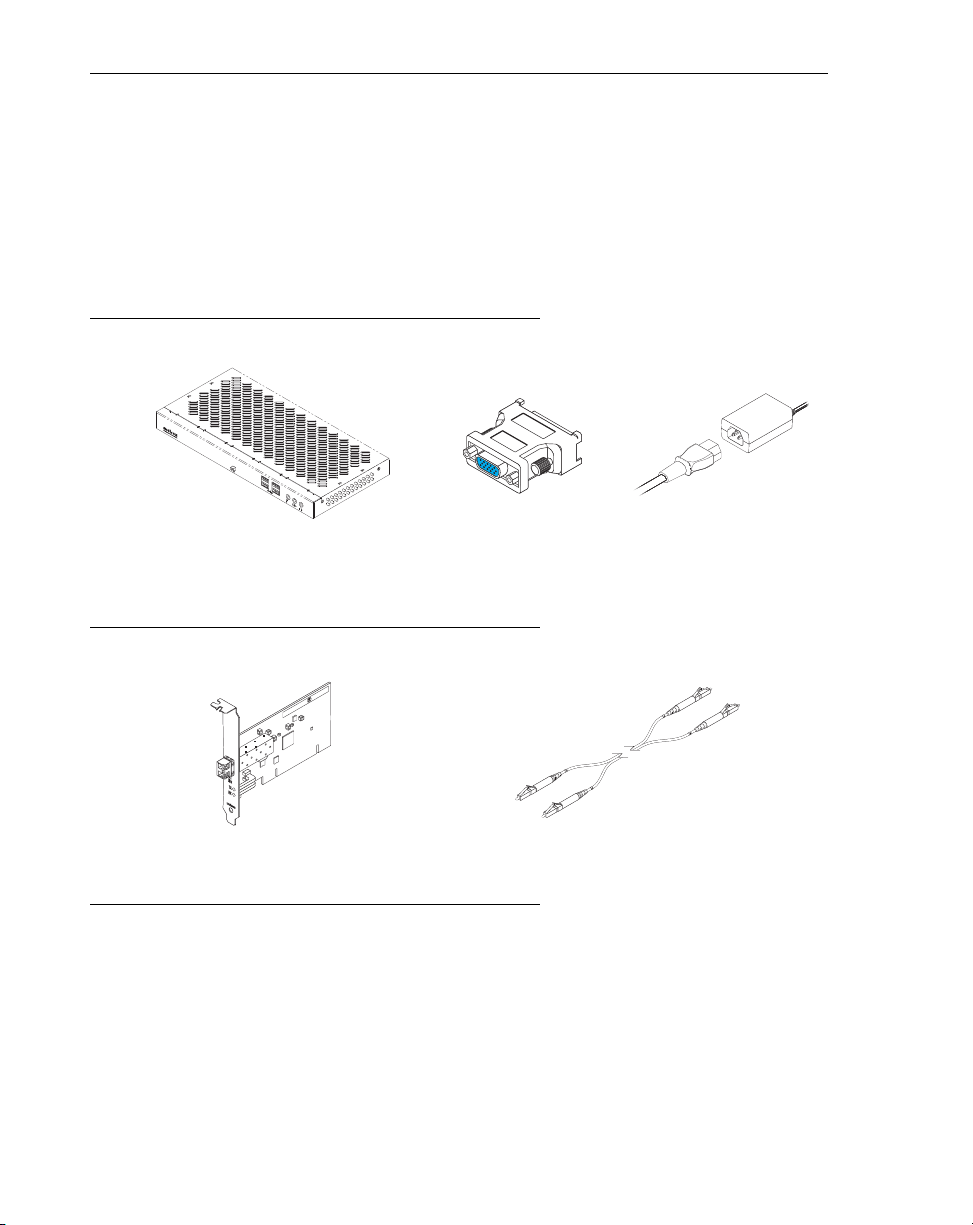
Hardware supplied
Matrox ATC RG remote graphics unit
(ATC RG-400SL shown)
* Multiple power cables are provided for international support.
Hardware required
Matrox PCI or PCIe interface card
(PCI card shown)
(sold separately)
Installation overview
To install your Matrox product:
1
Install your interface card – see “Hardware installation”, page 4.
2
Connect your ATC RG unit, monitors, and other peripherals – see “Connection setup”,
page 7.
4 DVI-to-HD15 adapters
(ATC RG-400SL only)
Dual LC optical cable
(
50 µm/125 µm or 62.5 µm/125 µm
Power supply
)
*
2 Matrox RG Series – User Guide
Page 3

3
Install the software. Your Matrox ATC RG product supports a number of operating
systems such as Windows, Unix, and Linux. To obtain a display driver for your operating
system, contact your Matrox representative.
Note: Windows XP SP2 (Service Pack 2)
– Windows may install a Matrox display driver
unsupported by your product when the hardware in your unit is detected. If you aren’t
prompted to install a display driver,
DON’T RESTART
your system. Manually install the
display driver on your Matrox installation CD-ROM before you restart.
If you’re installing an ATC RG-200DL unit with a dual link digital monitor, the display
driver used by Windows Service Pack 2 may disable your dual link DVI connector and
enable the HD-15 connector. To install a driver that supports the dual link feature of your
Matrox product, you need connect an analog monitor to the HD-15 connector.
Matrox RG Series – User Guide 3
Page 4
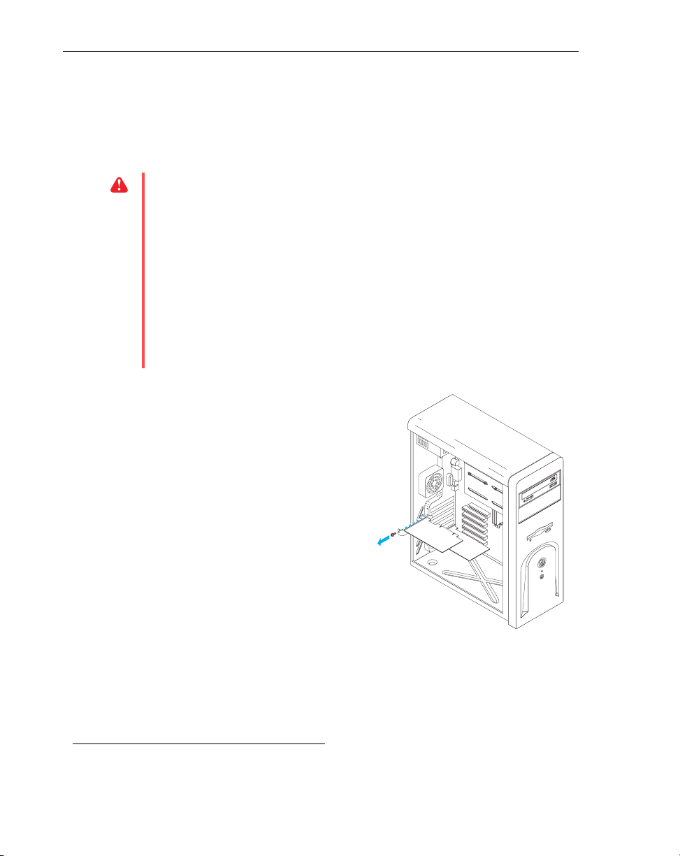
Hardware installation
This section describes how to install a Matrox interface card in your host computer. If your Matrox
interface card is already installed in your computer, skip to “Connection setup”, page 7. For
information specific to your computer, like how to remove its cover, see your system manual.
WA R N I N G:
To avoid personal injury and to prevent damage to your computer or Matrox
hardware, turn off your computer, unplug it, and then wait for it to cool before you install
your Matrox product and touch any of the internal parts of your computer.
While your computer is turned off but still plugged in, some electrical current is supplied
to the motherboard. This current may prevent newly installed hardware from working
properly.
Also, static electricity can severely damage electronic parts. Before touching any electronic
parts, drain static electricity from your body (for example, by touching the metal frame of
your computer). When handling a card, carefully hold it by its edges and avoid touching its
circuitry.
1
Open your computer and
remove your existing graphics
*
card
If a graphics card
your computer, skip to step 2.
a
Using
Windows
currently installed display drivers.
Restart your computer for the changes
to take effect.
After your computer restarts, you’re
prompted to install drivers for the new
graphics hardware detected. Click
Cancel
isn’t
already installed in
Add/Remove Programs
Control Panel
, remove any
.
in the
b
Turn off your computer and all peripherals such as your monitor or printer.
c
Open the computer and remove your existing graphics card. (If graphics hardware is
built into the motherboard of your computer, you may need to disable it manually after
your Matrox card is installed. For more information, see your system manual.)
* With multi-display mode, you may be able to use your existing graphics card. For Windows 2000/XP, see Windows 2000/XP
online help under “Install additional monitors”.
4 Matrox RG Series – User Guide
Page 5
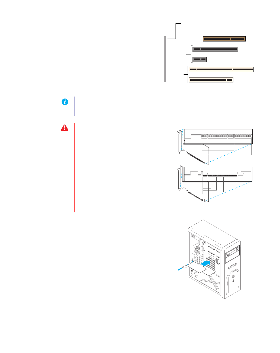
2
(64-bit)
(Back of computer)
(32-bit)
PCI
Express
slots
AGP slot
(×16)
(×1)
PCI
slots
PCI card
32-bit
64-bit
PCI Express card
×16
×1
×4
×8
an expansion slot for your
interface card
Most computers have different types of
expansion slots. Choose a PCI or PCI
Express (PCIe) ×1 slot, depending on the
type of Matrox card you have. If you have a
PCI card, your card supports both 64-bit
and 32-bit PCI slots. Your system manual
should identify the location of each type of
expansion slot in your computer.
Note:
If you’re using a PCI card in a 64-bit PCI slot, your choice of PCI slot may affect your
card or system performance. For more information, see your computer manual.
WA R N I N G:
Inserting your Matrox card
into the wrong type of slot could damage
your card, your computer, or both.
If you’re using a PCI interface card in a
64-bit PCI expansion slot, your card uses
only the part of your expansion slot closest
to the back of the computer.
3
Insert your Matrox interface
card
a
Position your Matrox card over the
expansion slot you’ve chosen.
b
Push the card in firmly and evenly until
it’s fully seated in the slot.
c
Secure the bracket of your Matrox card
to the computer frame.
Matrox RG Series – User Guide 5
Page 6

Your Matrox card is now installed.
Before restarting your computer
, first connect your RG400SL unit
to your computer, then connect your monitors and your peripherals to your unit (see “Connection
setup”, page 7).
After connecting
, restart your computer and install your Matrox software.
WA R N I N G:
If your computer doesn’t restart after your Matrox card is installed, turn off
your computer to avoid damaging electronic parts.
6 Matrox RG Series – User Guide
Page 7

Connection setup
Audio cables (stereo)
USB cables
Power cable
USB cables
Optical cables
Audio cable
(stereo or SPDIF)
Monitor connectors
(4 DVI for RG-400SL,
2 DVI + 2 HD-15 for RG-200DL)
This section describes how to connect monitors and other peripherals to your Matrox ATC RG unit.
Connection overview
Matrox RG Series – User Guide 7
Page 8
Step-by-step connection setup
Optical cable
Cable A
Cable B
Cable B
Cable A
Monitor
connector (DVI)
Monitor connector
(HD-15)
DVI-to-HD15
adapter
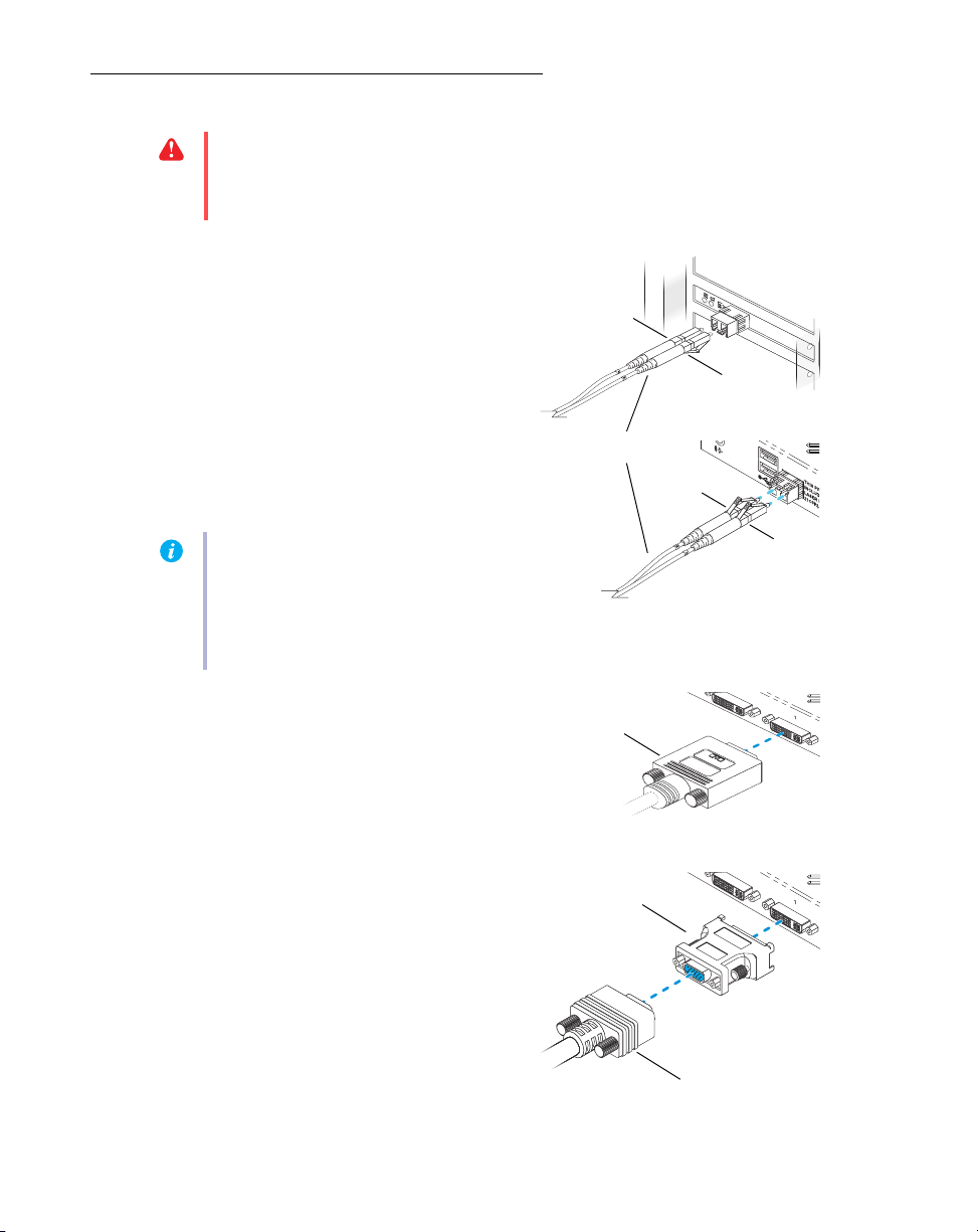
WA R N I N G:
Because the body of your ATC RG unit is used to disperse heat, it may become
warm to the touch. Make sure your unit is located in a well ventilated area and nothing is
blocking its ventilation holes.
1
Connect your unit to your
interface card
To connect your ATC RG unit to your
interface card, you need a dual LC optical
cable (sold separately).
Connect one end of your optical cable to the
optical connector of your interface card.
Connect the other end of your cable to the
optical connector on your unit. Make sure
your connectors are properly connected.
Note:
The maximum length of optical
cable supported by your Matrox product is
250 meters/750 feet. For more
information, see “Product information”,
page 12.
2
Connect your monitors
ATC RG-400SL
the monitor connectors at the back of your
ATC RG un i t.
– Connect your monitors to
8 Matrox RG Series – User Guide
If your monitors have DVI connectors,
connect them directly to the monitor
connectors at the back of your unit.
If your monitors have HD-15 connectors,
you need DVI-to-HD15 adapters to connect
your monitors to the monitor connectors on
your unit.
Page 9

ATC RG-200DL
Monitor connector
(HD-15)
Monitor
connector (DVI)
Power supply
cable
USB connectors
– Connect your mo nitors to
the monitor connectors at the back of your
Extio unit.
If your monitors have DVI connectors,
connect them directly to the DVI monitor
connectors (
A
) at the back of your unit.
If your monitors have HD-15 connectors,
connect them directly to the HD-15 monitor
connectors (
Note
B
) at the back of your unit.
: While a DVI monitor is connected
to a DVI connector on your unit, the
corresponding HD-15 connector is
disabled.
3
Connect the power supply
Attach one end of the power supply cable
provided with your Matrox product to the
power connector on your Matrox product.
Plug the power supply cord into an electrical
outlet.
4
Connect your input devices
(optional)
To use a keybo ard or mo use, s imp ly co nnect
a USB mouse or keyboard to one of the USB
connectors on your unit. There are 2 USB
connectors at the back of the unit and 4 at
the front.
Note:
USB devices (including keyboard and mouse) are unavailable until Windows starts.
Matrox RG Series – User Guide 9
Page 10

5
Audio connector
(SPDIF/Stereo)
Reception indicator light
Optical connector
Transmission indicator light
Connect your audio devices
(optional)
Your unit has 2 input and 2 output audio
connectors. The 2 input connectors are
in
() and
output audio connectors are
() and
Microphone
Line out
(). The 2
Headphones
( ). All audio
Line
connectors support stereo jack connectors.
The
Line out
connector also supports
SPDIF
(Sony/Philips Digital Interface Format) mini-
plug optical connectors.
To connect an audio device to your unit:
a
Plug one end of your audio cable into the audio connector on your unit.
b
Plug the other end of the cable in your audio device. For information on the type of
connector supported by your audio device, see its documentation.
Note:
If you’re using the headphone connector at the front of your unit, the line-out
connector at the back of the unit is muted.
Your Matrox product is now installed. Restart your computer, and install your Matrox software.
Verifying your interface connection
10 Matrox RG Series – User Guide
To check your interface connection, your computer and your ATC RG unit must be on.
On the bracket of your interface card, make
sure both the transmission (
reception (
RX
) indicator lights are green.
TX
) and
If the reception indicator is red and you have
separate optical cables, switch the cables in
the optical connector of your Matrox
product.
If the transmission indicator is red, your
optical connector may be loose. Make sure
your optical connector is firmly in place by
pushing it into its housing. If the light doesn’t change to green, contact your Matrox
representative.
Page 11

On your ATC RG unit, make sure the
Reception indicator light
Optical connector
reception indicator light is off while your
unit is turned on. This indicator light is
inside your unit next to the optical
connector. If the indicator light is on (red)
and you have separate optical cables, switch
the cables in the optical connector of your
Matrox product.
Note:
If the reception indicator lights on your interface card and your ATC RG unit are red
after changing the cables, your optical cable may be damaged. Try your connection with a
different optical cable.
Matrox RG Series – User Guide 11
Page 12

Product information
Remote unit features
Digital monitor support DVI (single and dual link) DVI (single link)
# of displays supported 24
Interface card supported Optical Optical
Memory 128 MB 128 MB
Maximum display
resolution
# of DVI-to-HD15 adapters —4
# of USB connectors
# and type of audio
connectors
Interface card features
Front: 1 microphone input,
Matrox ATC RG-200DL Matrox ATC RG-400SL
2048 × 2048 1920 × 1200
2.0 compliant
(2 in back, 4 in front)
Back: 1 stereo/SPDIF
output
1 line-in input, 1 stereo
output
2.0 compliant
(2 in back, 4 in front)
Back: 1 stereo/SPDIF
output
Front: 1 microphone input,
1 line-in input, 1 stereo
output
Interface type Optical
Card Type PCI or PCIe ×1
Form factor Low-profile
Cable type supported Dual-LC optical
Maximum distance (cable type)
Notes
Your Matrox graphics hardware is 100% VGA compatible and supports all VESA
standards: VBE 2.0 (Super VGA modes), DPMS (energy saving), and DDC-2B (Plugand-Play monitor).
To get the most of your Matrox product, we recommend using the highest color palette
setting (a 32-bit color palette) for all your displays.
12 Matrox RG Series – User Guide
250 m (50 µm/125 µm)
150 m (62.5 µm/125 µm)
Page 13

The display resolutions and refresh rates available depend on your Matrox graphics
hardware, display driver, software monitor settings, and monitor. For information on the
capabilities of your monitor, see your monitor documentation.
If you’re using multiple monitors, your Matrox hardware uses the same display
resolution and monitor settings for all your monitors. This display resolution and
monitor settings (such as refresh rate) are dependent on your operating system and your
display driver.
If you’re using BNC connectors with a Plug-and-Play monitor, the Plug-and-Play feature
of your monitor can’t be used. To use the Plug-and-Play feature of your monitor, instead
of the BNC connectors, use the 15-pin connector at the back of your monitor.
Supported VESA modes
(main display)
In the table below, VESA modes supported by your Matrox graphics hardware are indicated
by a VESA mode number. Many Super VGA DOS programs use VESA modes.
Display
resolution
640 × 400 — 100 — — —
640 × 480 (VGA) 101 110 111 112
800 × 600 102 103 113 114 115
1024 × 768 — 105 116 117 118
1280 × 1024 — 107 119 11A 11B
1600 × 1200 — 11C 11D 11E 11F
Columns25435060
80 ———108
132 109 10A 10B 10C
16 colors 256 colors 32 K colors 64 K colors 16 M colors
Rows
Matrox RG Series – User Guide 13
Page 14

Customer support
Matrox Web
Matrox is on the Internet with a World Wide Web (WWW) site. Our Web site has product literature,
press releases, technical material, a sales office list, trade show information, and other relevant
material.
Visit the Matrox Graphics Web site at www.matrox.com/graphics.
E-mail questions or comments regarding the site to webmaster@matrox.com.
If you have a problem
Matrox values your business and offers professional support for your Matrox product. For product
support, contact your Matrox representative or visit our technical support Web site at
www.matrox.com/graphics/support/
Information we need
Please give a complete description of the problem, and include:
Matrox card serial number, model number, revision number, BIOS number, driver type
and version, and memory address at which the Matrox card is installed.
.
Computer brand and model name.
Monitor brand and model name.
Operating system, version, and service pack.
Brand and model of any other cards and devices installed on your system.
Program specific problems
If a problem appears with a specific program, please give us the following information:
Display settings (color palette, display resolution, and so on) applied when the problem
occurs.
If possible, take note of the file and segment address that caused the problem.
Detailed steps known to cause the bug, so we can reproduce it.
14 Matrox RG Series – User Guide
Page 15

Warranty
A. Limited Warranty Statement
1. Matrox Graphics Inc. (“Matrox”) warrants to the end-user customer, who provides adequate proof of purchase that
Matrox hardware products purchased from Matrox authorized dealers will be free from defects in materials and
workmanship for a period of one (1) year from the date of purchase. This warranty applies only to the original enduser purchaser and is non-transferable. Conditions and limitations of Matrox’s warranty are stated below.
2. Matrox’s limited warranty covers only those defects which arise as a result of normal use of the hardware and does
not apply to any:
a. improper or inadequate maintenance;
b. incompatibilities due to the user’s hardware or software applications with or in which the Matrox product
interfaces;
c. product of a special or custom-made nature;
d. unauthorized modification or misuse;
e. improper installation, misapplication or negligence;
f. operation outside the product’s environmental specifications;
g. improper site preparation or maintenance;
h. software;
i. other causes that do not relate to a product defect;
j. defects or damage suffered as a result of force majeure (including theft);
k. defects or damage suffered as a result of normal wear and tear, and/or
l. stolen goods.
3. If Matrox receives, during the applicable warranty period, notice of a defect in a warranted hardware product and the
defective Matrox product in question, Matrox shall at its sole option, either repair or replace the product, and shall
return the repaired product or a replacement product within a reasonable delay. The replacement product may not be
new, provided that it has functionality at least equal to that of the product being replaced.
4. This warranty is valid in any country where Matrox hardware products are distributed by Matrox or its authorized
dealers.
5. This Limited Warranty Statement gives the customer specific legal rights. The customer may also have other rights
which vary from state to state in the United States, from province to province in Canada, and from country to country
elsewhere in the world.
B. Limitations of Warranty
1. NEITHER MATROX NOR ANY OF ITS THIRD PARTY SUPPLIERS MAKES ANY OTHER WARRANTY OF ANY KIND,
WHETHER EXPRESSED OR IMPLIED, WITH RESPECT TO MATROX PRODUCTS. MATROX SPECIFICALLY
DISCLAIMS (and the customer, by accepting the Matrox product, specifically accepts such disclaimer and waives)
ALL OTHER WARRANTIES, EITHER EXPRESSED OR IMPLIED, INCLUDING BUT NOT LIMITED TO THE IMPLIED
WARRANTIES OF MERCHANTABILITY AND FITNESS FOR A PARTICULAR OR INTENDED PURPOSE OR USE AND
THE WARRANTY AGAINST LATENT DEFECTS, WITH RESPECT TO THE HARDWARE AND/OR SOFTWARE.
MATROX FURTHER DISCLAIMS ANY WARRANTY THAT MATROX PRODUCTS, IN WHOLE OR IN PART, WILL BE
FREE FROM INFRINGEMENT OF ANY THIRD PARTY INTELLECTUAL PROPERTY OR PROPRIETARY RIGHTS.
2. To the extent that this Limited Warranty Statement is inconsistent with the law of the locality where the customer
purchases the Matrox product, this Limited Warranty Statement shall be deemed modified to be consistent with such
local law. Under such local law, certain limitations of this Limited Warranty Statement may not apply to the consumer.
3. To the extent allowed by local law, the remedies provided in this Limited Warranty Statement are the customer’s sole
and exclusive remedies.
Matrox RG Series – User Guide 15
Page 16

C. Limitations of Liability
1. EXCEPT FOR THE OBLIGATIONS SPECIFICALLY SET FORTH IN THE LIMITED WARRANTY STATEMENT, IN NO
EVENT SHALL MATROX BE LIABLE FOR:
a. any direct, indirect, special, incidental, consequential, foreseeable or unforeseeable, or punitive damages, whether
based on contract, tort, delict or any other legal theory and whether advised of the possibility of such damages,
and/or
b. damages arising from the loss of use, data, production revenue and/or profit of in connection with the Matrox
product or any business interruption.
2. Without prejudice to the foregoing, any liability of Matrox for any breach of warranty shall be limited to the amount
paid by the customer for the defective hardware in question.
3. To the extent allowed by local law, Matrox’s entire liability and the customer’s exclusive remedy shall be the repair or
replacement of any defective product during the warranty period. Matrox does not offer any other warranty with
respect to Matrox hardware or software or any other hardware or software.
4. Customer shall be responsible for all applicable taxes, duties and customs fees on any replacement unit, as well as
all transport, insurance, storage and other charges incurred on all returned products.
D. Obtaining Service
1. Verify that your Matrox product was installed and configured according to the information in its accompanying
documentation.
2. Read the “Troubleshooting” information included with the Matrox product to see if you can solve the problem yourself.
3. If you are still experiencing difficulties, please contact your dealer where you purchased your Matrox product.
4. If you must return a Matrox product, leave the configuration as it was when you were using it, and leave all
identification stickers on the product. Pack the product in its original box and return to your Matrox dealer where the
product was purchased, together with your proof of purchase. Your Matrox dealer will return the product for you.
Alternatively, if this first option is unavailable to you, you may contact the Matrox Technical Support group who will
issue an Return Merchandise Authorization (RMA) number, upon receipt of adequate proof of purchase, and inform
you of shipping instructions. DO NOT RETURN THE PRODUCT TO MATROX WITHOUT MATROX’S RMA NUMBER
AND EXPRESS AUTHORIZATION.
E. General
This limited warranty shall be governed by the laws of the Province of Quebec, Canada and the federal laws of Canada
applicable therein and the courts of the Province of Quebec shall have exclusive jurisdiction to hear and decide any
dispute instituted by the customer in connection with this limited warranty; the customer waives, by accepting the
product, its rights to institute proceedings in connection with this warranty against Matrox in any jurisdiction other than
Quebec.
16 Matrox RG Series – User Guide
Page 17

Software license agreement
Single User Products This Matrox software (the “Software”) is copyrighted by Matrox Graphics Inc. All rights are
reserved. The purchaser is granted a license to use the software only, subject to the following restrictions and limitations:
1. The license is for the original purchaser only, and is not transferable without written permission of Matrox.
2. The original purchaser may use the Software on a single computer owned or leased by the original purchaser. You
may not use the Software on more than a single computer, even if you own or lease more than one computer, without
written consent of Matrox.
3. The original purchaser may make back-up copies of the Software for his or her own use only, subject to the use
limitations of this license.
4. The original purchaser may not engage in, nor permit third parties to engage in, any of the following:
• Providing or disclosing the Software to third parties.
• Providing use of the Software in a computer service business, network, time-sharing, multiple CPU or multi-user
arrangement to users who are not individually licensed by Matrox.
• Making alterations or copies of any kind in the Software (except as specifically permitted above).
• Attempting to unassemble, de-compile or reverse engineer the Software in any way.
• Granting sublicenses, leases, or other rights in the Software to others.
• Making copies, or verbal or media translations, of the user’s guide.
• Making telecommunication data transmissions of the Software.
Matrox reserves the right to terminate this license if there is a violation of its term or default by the Original Purchaser.
Upon termination, for any reason, all copies of the Software must be immediately returned to Matrox, and the Original
Purchaser shall be liable to Matrox for any and all damages suffered as a result of the violation or default.
Limited warranty Matrox warrants to you, for a period of 90 days normal use from your date of purchase, that:
1. The CD/disks on which the software is furnished and the documentation are not defective.
2. The Software is properly recorded upon the CD/disks included.
3. The documentation is substantially complete and contains all the information Matrox deems necessary to use the
software.
4. The Software functions substantially as described in the documentation.
Matrox’s entire liability and your exclusive remedy shall be the replacement of any CD/Disks or documentation not
meeting these warranties, which is returned to Matrox or an authorized dealer, together with a copy of your paid receipt.
The above is the only warranty of any kind, either express or implied, including, but not limited to the implied warranties
of merchantability and fitness for a particular use that is made by Matrox on this Licensed Software. In no event shall
Matrox be liable to you or to any third party for consequential, special, indirect or incidental damages which you may
incur as a result of using the licensed software, including, but not limited to, loss of data, or information of any kind which
you may experience.
Matrox RG Series – User Guide 17
Page 18

Thank you for choosing Matrox
Please register online (http://www.matrox.com/graphics/en/registration) to be eligible
for customer support, new product announcements, and information on special offers
and upcoming events.
Page 19

USA
FCC Compliance Statement
Remark for the Matrox hardware products supported by this guide This equipment has been tested and found to
comply with the limits for a Class A digital device, pursuant to Part 15 of the FCC Rules. These limits are designed to
provide reasonable protection against harmful interference when the equipment is operated in a commercial
environment. This equipment generates, uses, and can radiate radio frequency energy and, if not installed and used in
accordance with the instructions manual, may cause harmful interference to radio communications. Operation of this
equipment in a residential area is likely to cause harmful interference in which case the user will be required to correct
the interference at his own expense.
WARNING Changes or modifications to this unit not expressly approved by the party responsible for the compliance
could void the user’s authority to operate this equipment. The use of shielded cables for connection of the monitor to
the card is required to meet FCC requirements.
CANADA
(English) Industry Canada Compliance Statement
Remark for the Matrox hardware products supported by this guide These digital apparatus does not exceed the
Class A limits for radio noise emission from digital devices set out in the Radio Interference Regulation of Industry
Canada.
(Français) Conformité avec les exigences du ministère de l’Industrie Canada
Remarque sur les produits matériels Matrox couverts par ce guide Ce present appareil numérique n’émet aucun
bruit radioélectrique dépassant les limites applicables aux appareils numériques de Classe A prescrites dans le
Règlement sur le brouillage radioélectrique édicté par Industrie Canada.
USA
(English) FDA (Food and Drug Administration) requirements for Laser Products
Remark for the Matrox hardware products supported by this guide This product includes a 850 nm Laser
Product compliant to 21CFR Subpart J Class 1.
JAPAN
VCCI Compliance Statement
Remark for the Matrox hardware products supported by this guide This is a Class A product based on the
standard of the Voluntary Control Council for Interference by Information Technology Equipment (VCCI). If this
equipment is used in a domestic environment, radio disturbance may occur, in which case, the user may be required to
take corrective actions.
EUROPE
(English) European user’s information – Declaration of Conformity
Remark for the Matrox hardware products supported by this guide These devices comply with EC
Directive 89/336/EEC for a Class A digital device. They have been tested and found to comply with
EN55022/CISPR22 and EN55024/CISPR24. In a domestic environment these products may cause radio interference in
which case the user may be required to take adequate measures. To meet EC requirements, shielded cables must be
used to connect the monitor and other peripherals to the card. These products have been tested in a typical class A
compliant host system. It is assumed that these products will also achieve compliance in any class A compliant system.
Page 20

(Français) Informations aux utilisateurs Européens – Déclaration de conformité
Remarque sur les produits matériels Matrox couverts par ce guide Ces unités sont conformes à la directive
communautaire 89/336/EEC pour les unités numériques de classe A. Les tests effectués ont prouvé qu’elles sont
conformes aux normes EN55022/CISPR22 et EN55024/CISPR24. Le fonctionnement de ces produits dans un
environnement résidentiel peut causer des interférences radio, dans ce cas l’utilisateur peut être amené à prendre les
mesures appropriées. Pour respecter les impératifs communautaires, les câbles de connexion entre le moniteur ou
autres périphériques et la carte doivent être blindés. Ces produits ont été testés dans un système hôte typique
compatible classe A. On suppose qu’ils présenteront la même compatibilité dans tout système compatible classe A.
(Deutsch) Information für europäische Anwender – Konformitätserklärung
Anmerkung für die Matrox Hardware-Produktunterstützung durch dieses Handbuch Diese Geräte entsprechen
EC Direktive 89/336/EEC für ein digitales Gerät Klasse A. Sie wurden getestet und entsprechen demnach
EN55022/CISPR22 und EN55024/CISPR24. In einer Wohnumgebung können diese Produkte Funkinterferenzen
erzeugen, und der Benutzer kann genötigt sein, entsprechende Maßnahmen zu ergreifen. Um EG-Anforderungen zu
entsprechen, müssen zum Anschließen des Monitors und anderer Peripheriegeräte an die Karte abgeschirmte Kabel
verwendet werden. Diese Produkt wurden in einem typischen, der Klasse A entsprechenden, Host-System getestet. Es
wird davon ausgegangen, daß diese Produkte auch in jedem Klasse A entsprechenden System entsprechend
funktionieren.
(Italiano) Informazioni per gli utenti europei – Dichiarazione di conformità
Nota per i prodotti hardware Matrox supportati da questa guida Questi dispositivi sono conformi alla direttiva
CEE 89/336/EEC relativamente ai dispositivi digitali di Classe A. Sono stati provati e sono risultati conformi alle norme
EN55022/CISPR22 e EN55024/CISPR24. In un ambiente domestico, questi prodotti possono causare radiointerferenze,
nel qual caso all’utente potrebbe venire richiesto di prendere le misure adeguate. Per soddisfare i requisiti CEE, il monitor
e le altre periferiche vanno collegati alla scheda grafica con cavi schermati. Questi prodotti sono stati provati in un tipico
sistema host conforme alla clas se A. Inoltre, si dà per scontato che questi prodotti acquisiranno la conformità in qualsiasi
sistema conforme alla classe A.
(Español) Información para usuarios europeos – Declaración de conformidad
Observación referente a los productos de hardware de Matrox apoyados por este manual Estos dispositivos
cumplen con la directiva de la CE 89/336/EEC para dispositivos digitales de Clase A. Dichos dispositivos han sido
sometidos a prueba y se ha comprobado que cumplen con las normas EN55022/CISPR22 y EN55024/CISPR24. En
entornos residenciales, estos productos pueden causar interferencias en las comunicaciones por radio; en tal caso el
usuario deberá adoptar las medidas adecuadas. Para satisfacer las disposiciones de la CE, deberán utilizarse cables
apantallados para conectar el monitor y demás periféricos a la tarjeta. Estos productos han sido sometidos a prueba en
un típico sistema anfitrión que responde a los requisitos de la clase A. Se supone que estos productos cumplirán
también con las normas en cualquier sistema que responda a los requisitos de la clase A.
EUROPE
(English) European user’s information – Directive on Waste Electrical and
Electronic Equipment (WEEE)
Please refer to the Matrox Web site (www.matrox.com/environment/weee) for recycling information.
(Français) Informations aux utilisateurs Européens – Règlementation des
déchets d’équipements électriques et électroniques (DEEE)
Se référer au site Web de Matrox (www.matrox.com/environment/weee) pour l’information concernant le recyclage.
(Deutsch) Information für europäische Anwender – Europäische Regelungen zu Elektround Elektronikaltgeräten
Bitte wenden Sie sich an der Matrox-Website (www.matrox.com/environment/weee) für Recycling-Informationen.
(WEEE)
(Italiano) Informazioni per gli utenti europei – Direttiva sui rifiuti di apparecchiature
elettriche ed elettroniche (RAEE)
Si prega di riferirsi al sito Web Matrox (www.matrox.com/environment/weee) per le informazioni di riciclaggio.
Page 21

FRANCE
Avertissement sur l’épilepsie
À lire avant toute utilisation d’un jeu vidéo par vous-même ou votre enfant Certaines personnes sont
susceptibles de faire des crises d’épilepsie ou d’avoir des pertes de conscience à la vue de certains types de lumières
clignotantes ou d’éléments fréquents dans notre environnement quotidien. Ces personnes s’exposent à des crises
lorsqu’elles regardent certaines images télévisées ou qu’elles jouent à certains jeux vidéo. Ces phénomènes peuvent
apparaître alors même que le sujet n’a pas d’antécédent médical ou n’a jamais été confronté à une crise d’épilepsie.
Si vous-même ou un membre de votre famille avez déjà présenté des symptômes liés à l’épilepsie (crise ou perte de
conscience) en présence de stimulations lumineuses, veuillez consulter votre médecin avant toute utilisation.
Nous conseillons aux parents d’être attentifs à leurs enfants lorsqu’ils jouent avec des jeux vidéo. Si vous-même ou votre
enfant présentez un des symptômes suivants: vertige, trouble de la vision, contraction des yeux ou des muscles, perte
de conscience, trouble de l’orientation, mouvement involontaire ou convulsion, veuillez immédiatement cesser de jouer
et consultez un médecin.
Précautions à prendre dans tous les cas pour l’utilisation d’un jeu vidéo Ne vous tenez pas trop près de l’écran.
• Jouez à bonne distance de l’écran de TV et aussi loin que le permet le cordon de raccordement. • Utilisez de
préférence les jeux de vidéo sur un écran de petite taille. • Évitez de jouer si vous êtes fatigué ou si vous manquez de
sommeil. • Assurez-vous que vous jouez dans une pièce bien éclairée. • En cours d’utilisation, faites des pauses de dix
à quinze minutes toutes les heures.
MACROVISION
(English) A. Apparatus claims of US patent numbers 4,631,603, 4,577,216, 4,819,098, and 4,907,093 licensed for
limited viewing uses only. B. This product incorporates copyright protection technology that is protected by method
claims of certain U.S. patents and other intellectual property rights owned by Macrovision Corporation and other rights
owners. Use of this copyright protection technology must be authorized by Macrovision Corporation, and is intended
for home and other limited viewing uses only unless otherwise authorized by Macrovision Corporation. Reverse
engineering or disassembly is prohibited.
(Français) A. Demande de numéros de brevet aux États-Unis 4,631,603, 4,577,216, 4,819,098 et 4,907,093 avec
licence pour des utilisations limitées d’affichage uniquement. B. Ce produit bénéficie d’une technologie de protection
de droits d’auteur mis en œuvre par des demandes de brevets américains et d’autres droits de propriété intellectuelle
de Macrovision Corporation et d’autres propriétaires de droits. L’utilisation de cette technologie de protection de droits
d’auteur doit être autorisée par Macrovision Corporation, et est destinée à des utilisations domestiques ou de
consultation limitée autorisées par Macrovision Corporation. L’ingénierie à rebours ou le désassemblage est interdit.
(Deutsch) A. Patentansprüche für Geräte mit US-Patentnummern 4.631.603, 4.577.216, 4.819.098 und 4.907.093,
die nur für eingeschränkte Anzeigen lizenziert sind. B. Dieses Produkt enthält urheberrechtlich geschützte
Technologie, die durch Patentansprüche bestimmter US-Patente und andere geistige Eigentumsrechte der Macrovision
Corporation und anderen Eigentümern von Rechten geschützt sind. Die Verwendung dieser urheberrechtlich
geschützten Technologie muß von der Macrovision Corporation genehmigt werden und darf nur zum Abspielen für
private Zwecke und anderen Einschränkungen unterliegende Zwecke eingesetzt werden, sofern keine Genehmigung für
andere Zwecke von Macrovision vorliegt. Reverse Engineering und Disassemblieren ist untersagt.
(Italiano) A. Diritti di brevetto USA n. 4,631,603, 4,577,216, 4,819,098 e 4,907,093 in licenza solamente per la
visualizzazione limitata. B. Questo prodotto incorpora una tecnologia per la protezione dei diritti d’autore che è
coperta da brevetti USA e da altri diritti di proprietà intellettuale detenuti da Macrovision Corporation e da altri titolari.
L’utilizzo di questa tecnologia di protezione dei diritti d’autore deve essere autorizzato da Macrovision Corporation, ed
è intesa solamente per la visione casalinga ed altri utilizzi limitati salvo diversa autorizzazione di Macrovision
Corporation. È proibito il disassemblaggio o procedimenti di reverse engineering.
(Español) A. Aparato patentado en los EE.UU. con los números siguientes. 4,631,603, 4,577,216, 4,819,098 y
4,907,093 con licencia para visualización limitada únicamente. B. Este producto incorpora una tecnología de
protección por Copyright mediante la demanda de ciertas patentes en los EE.UU. y otros derechos de propiedad
intelectual de Macrovision Corporation y otros propietarios de los derechos. La utilización de esta tecnología de
protección por Copyright debe ser autorizada por Macrovision Corporation y está destinada a su utilización doméstica
y otras formas de visualización limitada, a menos que Macrovision Corporation exprese lo contrario. Está prohibida la
utilización de técnicas de ingeniería inversa y el desmontaje.
Page 22

Copyright © 2009 Matrox Graphics Inc. • (English) All rights reserved. • (Français) Tous droits réservés. • (Deutsch) Alle
Rechte vorbehalten. • (Italiano) Tutti i diritti riservati. • (Español) Reservados todos los derechos.
Trademarks • Marques déposées • Warenzeichen • Marchi registrati •
Marcas registradas
Matrox Electronic Systems Ltd. /
Matrox Graphics Inc.................................................. Matrox
Adobe Systems Inc. ................................................. Acrobat
Apple Computer, Inc. ............................................... Apple®, Mac®, Mac OS
Belden Inc. ............................................................... Belden
Dolby Laboratories, Inc. ............................................ Dolby®, Dolby Digital
Intel Corporation ....................................................... Intel®, Pentium
International Business Machines Corporation .......... IBM®, VGA
Macrovision Corporation........................................... Macrovision™
Microsoft Corporation ............................................... Aero™, Direct3D
Silicon Graphics, Inc. ................................................OpenGL
Silicon Image, Inc...................................................... PanelLink™
U.S. Environmental Protection Agency ..................... Energy Star™
®
, DualHead®, CenterWINDOW™, DVDMax™,
GigaColor™, ASM™, ATC™, AuroraVX3mp™, AuroraVX™, DFC™,
DLC™, DualHead2Go™, Epic
A
™, Equinox™, Extio™, G400™,
G450™, G550™, ICP™, Marvel™, MED2mp™, MED2mp-DVI™,
MED3mp-DVI™, MED4mp™, MED5mp-DVI™, MED5mp™,
Millennium™, MMS™, Multi-Monitor Series™, MultiDesk™,
P650™, P650™ Low-profile, P690™, P750™, Parhelia™,
Parhelia™ APVe, Parhelia-512™, Parhelia-LX™, Parhelia HR256™,
PJ4OLP™, PowerDesk™, PowerSpace™, QID™, Quad
Information Display™, RAD™, Quick Connect™, MaxVIEW™,
MGA™, MGA-G100™, MGA-G200™, Onyx™, PixelTOUCH™,
PrecisionCAD™, Precision SGT™, QuickDesk™, RAD2mp™,
RAD3mp™, RAD9mp™, RAD PCI™, RAD PCIe™, RADQ2mp™,
Rainbow Runner
®
, SonoVUE™, SPECTRUM™, TheatreVUE™,
TripleHead™, TripleHead2Go™, VDA™, Veos™, Xenia™
®
®
Microsoft
Windows Server
®
, Reader
®
®
®
®
®
, DirectDraw®, DirectShow™, DirectX™,
®
, MS-DOS®, PowerPoint®, Windows®, Windows NT®,
®
, Windows Vista™
®
• (English) Registered trademarks are registered in the United States, Canada, and/or other countries. All other nationally
and internationally recognized trademarks and tradenames are hereby acknowledged. • (Français) Les marques
déposées sont déposées aux États-Unis, au Canada et/ou dans d’autres pays. Toutes les autres marques et tous les
autres noms déposés reconnus nationalement ou internationalement sont également reconnus par les présentes. •
(Deutsch) Die eingetragenen Warenzeichen sind in den USA, Kanada und/oder anderen Ländern registriert. Alle
sonstigen national und international bekannten Warenzeichen und Produktnamen werden hiermit anerkannt. • (Italiano)
I marchi registrati sono registrati negli Stati Uniti, in Canada e/o in altri paesi. Tutti gli altri marchi registrati e nomi
commerciali riconosciuti a livello nazionale e internazionale sono ugualmente riconosciuti qui. • (Español) Las marcas
registradas están registradas en los EE.UU., Canadá u otros países. Por medio del presente se reconocen todas las
demás marcas y nombres comerciales reconocidos a nivel nacional e internacional.
Page 23

(English) Disclaimer
THE INFORMATION IN THIS GUIDE IS SUBJECT TO CHANGE AT ANY TIME AND WITHOUT NOTICE.
Matrox Graphics Inc. reserves the right to make changes in specifications at any time and without notice. The
information provided by this document is believed to be accurate and reliable. However, no responsibility is assumed by
Matrox Graphics Inc. for its use; nor for any infringements of patents or other rights of third parties resulting from its use.
No license is granted under any patents or patent rights of Matrox Graphics Inc.
(Français) Responsabilité
LES INFORMATIONS CONTENUES DANS CE MANUEL PEUVENT ÊTRE MODIFIÉES À TOUT MOMENT SANS
PRÉAVIS.
Matrox Graphics Inc. se réserve le droit de modifier les spécifications à tout moment sans préavis. Les informations
contenues dans ce manuel sont reconnues comme étant précises et fiables. Cependant, Matrox Graphics Inc. n’assume
aucune responsabilité concernant leur utilisation, ni leur contrefaçon ou les autres droits des tiers résultant de leur
utilisation. Aucune licence n’est accordée sur aucun brevet ou droit d’exploiter un brevet de Matrox Graphics Inc.
(Deutsch) Haftungsablehnungserklärung
DIE IN DIESEM HANDBUCH ENTHALTENEN ANGABEN UND DATEN KÖNNEN OHNE VORHERIGE ANKÜNDIGUNG
GEÄNDERT WERDEN.
Die Matrox Graphics Inc. behält sich das Recht vor, jederzeit und ohne Ankündigung technische Daten zu ändern. Es
wird keine Garantie für die Richtigkeit des Inhalts dieses Handbuchs übernommen. Weiterhin übernimmt die Matrox
Graphics Inc. keinerlei Verantwortung für die Benutzung dieses Handbuchs, weder für Verstöße gegen Patentrechte
noch für andere Rechte Dritter, die aus seinem Gebrauch resultieren mögen. Es werden keinerlei Lizenzrechte gewährt
für sämtliche Patente oder Patentrechte der Matrox Graphics Inc.
(Italiano) Discrezionalità
LE INFORMAZIONI CONTENUTE NEL PRESENTE DOCUMENTO SONO SOGGETTE A MODIFICHE SENZA
PREAVVISO.
Matrox Graphics Inc. si riserva il diritto di apportare variazioni di qualunque tipo alle specifiche tecniche in qualunque
momento e senza alcun preavviso. Le informazioni contenute in questa documentazione sono ritenute corrette e
attendibili. In ogni caso, non è imputabile a Matrox Graphics Inc. nessuna responsabilità per il loro utilizzo, come
nessuna violazione a brevetti o diritti di altri produttori derivante dal loro utilizzo.
(Español) Renuncia
LA INFORMACION QUE CONTIENE EL PRESENTE MANUAL ESTA SUJETA A CAMBIOS SIN PREVIO AVISO EN
CUALQUIER MOMENTO.
Matrox Graphics Inc. se reserva el derecho de realizar modificaciones en cualquier momento y sin previo aviso. La
información facilitada en este documento se considera que es exacta y fiable. Sin embargo, Matrox Graphics Inc. no
asume ninguna responsabilidad por su uso; ni por cualquier infracción de patentes u otros derechos de terceras partes
derivados de su uso. No se concede ninguna licencia bajo cualesquiera patentes o derechos de patentes de Matrox
Graphics Inc.
Page 24

Matrox Graphics Inc.
1055 Saint Regis Boulevard
Dorval, Quebec, Canada H9P 2T4
North America: 1-800-361-1408
International: (514) 822-6000
Email: graphics@matrox.com
Web site: www.matrox.com/graphics
Technical support:
www.matrox.com/graphics/support
To locate the sales office nearest you, visit
www.matrox.com/graphics/contact
 Loading...