

Page 1

Matrox 4Sight-M
Installation and Hardware Reference
Manual no. 10916-101-0100
February 28, 2005
MATROX IMAGING est distribué par TECHWAY - www.techway.fr - info@techway.fr - +33 (0)1 64 86 58 30
Page 2

Matrox® is a registered trademark of Matrox Electronic Systems Ltd.
Microsoft® and Windows® are registered trademarks of Microsoft
Corporation.
PC/104™ and PC/104-Plus™ are trademarks of the PC/104 Consortium.
Intel
®
is a registered trademark of Intel Corporation.
Pentium
®
is a registered trademark of Intel Corporation.
Celeron™ is a trademark of Intel Corporation.
Phoenix™ is a trademark of Phoenix Technologies Ltd.
Fujitsu hard disk drives are products of Fujitsu Limited.
Energizer
®
is a registered trademark of Eveready Battery Company Inc.
All other nationally and internationally recognized trademarks and
tradenames are hereby acknowledged.
© Copyright Matrox Electronic Systems Ltd., 2005. All rights reserved.
Limitation of Liabilities: In no event will Matrox or its suppliers be liable
for any indirect, special, incidental, economic, cover or consequential
damages arising out of the use of or inability to use the product, user
documentation or related technical support, including without
limitation, damages or costs relating to the loss of profits, business,
goodwill, even if advised of the possibility of such damages. In no
event will Matrox and its suppliers’ liability exceed the amount paid by
you, for the product.
Because some jurisdictions do not allow the exclusion or limitation of
liability for consequential or incidental damages, the above limitation
may not apply to you.
Disclaimer: Matrox Electronic Systems Ltd. reserves the right to make
changes in specifications at any time and without notice. The
information provided by this document is believed to be accurate and
reliable. However, neither Matrox Electronic Systems Ltd. nor its suppliers
assume any responsibility for its use; or for any infringements of patents
or other rights of third parties resulting from its use. No license is granted
under any patents or patent right of Matrox Electronic Systems Ltd.
PRINTED IN CANADA
MATROX IMAGING est distribué par TECHWAY - www.techway.fr - info@techway.fr - +33 (0)1 64 86 58 30
Page 3

Contents
Using this manual . . . . . . . . . . . . . . . . . . . . . . . . . . . . . . . . . . . . . . . . . . . . . . . . . . . . 9
Part 1: Operating your Matrox 4Sight-M unit
Chapter 1: Before you begin . . . . . . . . . . . . . . . . . . . . . . . . . . . . . 13
Overview . . . . . . . . . . . . . . . . . . . . . . . . . . . . . . . . . . . . . . . . . . . . . . . . . . . . . . . . . . 14
Hardware components. . . . . . . . . . . . . . . . . . . . . . . . . . . . . . . . . . . . . . . . . . . . . . . . 14
Motherboard . . . . . . . . . . . . . . . . . . . . . . . . . . . . . . . . . . . . . . . . . . . . . . . . . 14
Mass storage . . . . . . . . . . . . . . . . . . . . . . . . . . . . . . . . . . . . . . . . . . . . . . . . . . 16
Chassis . . . . . . . . . . . . . . . . . . . . . . . . . . . . . . . . . . . . . . . . . . . . . . . . . . . . . . 16
Memory . . . . . . . . . . . . . . . . . . . . . . . . . . . . . . . . . . . . . . . . . . . . . . . . . . . . . 17
Optional components . . . . . . . . . . . . . . . . . . . . . . . . . . . . . . . . . . . . . . . . . . . . . . . . 17
Matrox frame grabbers . . . . . . . . . . . . . . . . . . . . . . . . . . . . . . . . . . . . . . . . . . 17
Inspecting your Matrox 4Sight-M package. . . . . . . . . . . . . . . . . . . . . . . . . . . . . . . . . 18
Integrated-unit version . . . . . . . . . . . . . . . . . . . . . . . . . . . . . . . . . . . . . . . . . . 18
Motherboard-only version . . . . . . . . . . . . . . . . . . . . . . . . . . . . . . . . . . . . . . . 19
Additional components . . . . . . . . . . . . . . . . . . . . . . . . . . . . . . . . . . . . . . . . . 20
Operating your Matrox 4Sight-M unit. . . . . . . . . . . . . . . . . . . . . . . . . . . . . . . . . . . . 21
Light emitting diodes (LEDs). . . . . . . . . . . . . . . . . . . . . . . . . . . . . . . . . . . . . 21
Handling precautions . . . . . . . . . . . . . . . . . . . . . . . . . . . . . . . . . . . . . . . . . . . 22
Turning off the integrated-unit version of Matrox 4Sight-M. . . . . . . . . . . . . . 22
MATROX IMAGING est distribué par TECHWAY - www.techway.fr - info@techway.fr - +33 (0)1 64 86 58 30
Page 4

Chapter 2: Connecting peripherals to the unit . . . . . . . . . . . . . . 23
Overview . . . . . . . . . . . . . . . . . . . . . . . . . . . . . . . . . . . . . . . . . . . . . . . . . . . . . . . . . . 24
Connecting display devices . . . . . . . . . . . . . . . . . . . . . . . . . . . . . . . . . . . . . . . . . . . . 25
Connecting a high-resolution display device. . . . . . . . . . . . . . . . . . . . . . . . . . 26
Connecting a digital flat panel . . . . . . . . . . . . . . . . . . . . . . . . . . . . . . . . . . . . 27
Connecting NTSC/PAL video output devices . . . . . . . . . . . . . . . . . . . . . . . . 27
Connecting a USB mouse, keyboard, or printer. . . . . . . . . . . . . . . . . . . . . . . . . . . . . 28
Connecting other USB devices . . . . . . . . . . . . . . . . . . . . . . . . . . . . . . . . . . . . . . . . . 28
Networking connections . . . . . . . . . . . . . . . . . . . . . . . . . . . . . . . . . . . . . . . . . . . . . . 28
Connecting video input devices . . . . . . . . . . . . . . . . . . . . . . . . . . . . . . . . . . . . . . . . . 30
Units with a Matrox Meteor-II /Standard . . . . . . . . . . . . . . . . . . . . . . . . . . . . 30
Units with Matrox Meteor-II /Multi-Channel . . . . . . . . . . . . . . . . . . . . . . . . 32
Units with Matrox Meteor-II /Digital. . . . . . . . . . . . . . . . . . . . . . . . . . . . . . . 33
Units with Matrox Meteor-II /Camera Link. . . . . . . . . . . . . . . . . . . . . . . . . . 33
Connecting devices to the serial port . . . . . . . . . . . . . . . . . . . . . . . . . . . . . . . . . . . . . 34
Connecting devices to the auxiliary I/O interface. . . . . . . . . . . . . . . . . . . . . . . . . . . . 34
Connecting a stereo audio device. . . . . . . . . . . . . . . . . . . . . . . . . . . . . . . . . . . . . . . . 35
Part 2: Customizing the motherboard
Chapter 3: Adding devices to the Matrox 4Sight-M motherboard 39
Introduction . . . . . . . . . . . . . . . . . . . . . . . . . . . . . . . . . . . . . . . . . . . . . . . . . . . . . . . 40
Removing the Matrox 4Sight-M chassis. . . . . . . . . . . . . . . . . . . . . . . . . . . . . . . . . . . 41
Connecting a hard disk or CD drive . . . . . . . . . . . . . . . . . . . . . . . . . . . . . . . . . . . . . 43
Connecting devices with an ATA 44-pin connector . . . . . . . . . . . . . . . . . . . . 43
Connecting devices with an ATA 40-pin connector . . . . . . . . . . . . . . . . . . . . 44
Connecting both types of IDE devices . . . . . . . . . . . . . . . . . . . . . . . . . . . . . . 45
Drive assignments . . . . . . . . . . . . . . . . . . . . . . . . . . . . . . . . . . . . . . . . . . . . . 45
MATROX IMAGING est distribué par TECHWAY - www.techway.fr - info@techway.fr - +33 (0)1 64 86 58 30
Page 5

Connecting a PC/104-Plus board . . . . . . . . . . . . . . . . . . . . . . . . . . . . . . . . . . . . . . . . 46
Some considerations . . . . . . . . . . . . . . . . . . . . . . . . . . . . . . . . . . . . . . . . . . . . 46
Removing and installing memory. . . . . . . . . . . . . . . . . . . . . . . . . . . . . . . . . . . . . . . . 47
Removing memory . . . . . . . . . . . . . . . . . . . . . . . . . . . . . . . . . . . . . . . . . . . . . 47
Installing memory. . . . . . . . . . . . . . . . . . . . . . . . . . . . . . . . . . . . . . . . . . . . . . 48
Adjusting your new memory settings . . . . . . . . . . . . . . . . . . . . . . . . . . . . . . . 48
Chapter 4: Installing the Matrox 4Sight-M motherboard in a custom
chassis . . . . . . . . . . . . . . . . . . . . . . . . . . . . . . . . . . . . . . . . . . . . . . . 49
Overview . . . . . . . . . . . . . . . . . . . . . . . . . . . . . . . . . . . . . . . . . . . . . . . . . . . . . . . . . . 50
Custom chassis. . . . . . . . . . . . . . . . . . . . . . . . . . . . . . . . . . . . . . . . . . . . . . . . . . . . . . 50
Custom fan . . . . . . . . . . . . . . . . . . . . . . . . . . . . . . . . . . . . . . . . . . . . . . . . . . . . . . . . 51
Custom power supply. . . . . . . . . . . . . . . . . . . . . . . . . . . . . . . . . . . . . . . . . . . . . . . . . 52
Part 3: Reference material for all users
Chapter 5: Matrox 4Sight-M hardware reference. . . . . . . . . . . . . 55
Overview . . . . . . . . . . . . . . . . . . . . . . . . . . . . . . . . . . . . . . . . . . . . . . . . . . . . . . . . . . 56
Motherboard . . . . . . . . . . . . . . . . . . . . . . . . . . . . . . . . . . . . . . . . . . . . . . . . . . . . . . . 56
Processing. . . . . . . . . . . . . . . . . . . . . . . . . . . . . . . . . . . . . . . . . . . . . . . . . . . . . . . . . . 57
Memory . . . . . . . . . . . . . . . . . . . . . . . . . . . . . . . . . . . . . . . . . . . . . . . . . . . . . . . . . . . 59
Display. . . . . . . . . . . . . . . . . . . . . . . . . . . . . . . . . . . . . . . . . . . . . . . . . . . . . . . . . . . . 59
Encoder . . . . . . . . . . . . . . . . . . . . . . . . . . . . . . . . . . . . . . . . . . . . . . . . . . . . . 60
TMDS transmitter . . . . . . . . . . . . . . . . . . . . . . . . . . . . . . . . . . . . . . . . . . . . . 60
Mass storage. . . . . . . . . . . . . . . . . . . . . . . . . . . . . . . . . . . . . . . . . . . . . . . . . . . . . . . . 60
BIOS . . . . . . . . . . . . . . . . . . . . . . . . . . . . . . . . . . . . . . . . . . . . . . . . . . . . . . . . . . . . . 61
Networking . . . . . . . . . . . . . . . . . . . . . . . . . . . . . . . . . . . . . . . . . . . . . . . . . . . . . . . . 61
MATROX IMAGING est distribué par TECHWAY - www.techway.fr - info@techway.fr - +33 (0)1 64 86 58 30
Page 6

I/O interfaces. . . . . . . . . . . . . . . . . . . . . . . . . . . . . . . . . . . . . . . . . . . . . . . . . . . . . . . 62
Serial ports . . . . . . . . . . . . . . . . . . . . . . . . . . . . . . . . . . . . . . . . . . . . . . . . . . . 62
Audio interface. . . . . . . . . . . . . . . . . . . . . . . . . . . . . . . . . . . . . . . . . . . . . . . . 65
Parallel port . . . . . . . . . . . . . . . . . . . . . . . . . . . . . . . . . . . . . . . . . . . . . . . . . . 65
Auxiliary I/O interface . . . . . . . . . . . . . . . . . . . . . . . . . . . . . . . . . . . . . . . . . . 65
USB interface . . . . . . . . . . . . . . . . . . . . . . . . . . . . . . . . . . . . . . . . . . . . . . . . . 65
PC/104-Plus interface . . . . . . . . . . . . . . . . . . . . . . . . . . . . . . . . . . . . . . . . . . . . . . . . 66
Power supply, fan, and chassis . . . . . . . . . . . . . . . . . . . . . . . . . . . . . . . . . . . . . . . . . . 66
Power supply . . . . . . . . . . . . . . . . . . . . . . . . . . . . . . . . . . . . . . . . . . . . . . . . . 67
Fan. . . . . . . . . . . . . . . . . . . . . . . . . . . . . . . . . . . . . . . . . . . . . . . . . . . . . . . . . 67
Chassis . . . . . . . . . . . . . . . . . . . . . . . . . . . . . . . . . . . . . . . . . . . . . . . . . . . . . . 68
Part 4: Appendices
Appendix A: BIOS reference. . . . . . . . . . . . . . . . . . . . . . . . . . . . . 73
Introduction . . . . . . . . . . . . . . . . . . . . . . . . . . . . . . . . . . . . . . . . . . . . . . . . . . . . . . . 74
The BIOS Setup utility . . . . . . . . . . . . . . . . . . . . . . . . . . . . . . . . . . . . . . . . . . . . . . . 74
Entering the Setup utility . . . . . . . . . . . . . . . . . . . . . . . . . . . . . . . . . . . . . . . . 74
The Menu bar . . . . . . . . . . . . . . . . . . . . . . . . . . . . . . . . . . . . . . . . . . . . . . . . 75
The Legend bar . . . . . . . . . . . . . . . . . . . . . . . . . . . . . . . . . . . . . . . . . . . . . . . 76
The Selection window . . . . . . . . . . . . . . . . . . . . . . . . . . . . . . . . . . . . . . . . . . 76
The Item Specific Help window . . . . . . . . . . . . . . . . . . . . . . . . . . . . . . . . . . . 77
Main menu . . . . . . . . . . . . . . . . . . . . . . . . . . . . . . . . . . . . . . . . . . . . . . . . . . . . . . . . 78
Master and Slave submenus . . . . . . . . . . . . . . . . . . . . . . . . . . . . . . . . . . . . . . 79
Cache memory submenu . . . . . . . . . . . . . . . . . . . . . . . . . . . . . . . . . . . . . . . . 84
Boot options submenu . . . . . . . . . . . . . . . . . . . . . . . . . . . . . . . . . . . . . . . . . . 85
Advanced menu. . . . . . . . . . . . . . . . . . . . . . . . . . . . . . . . . . . . . . . . . . . . . . . . . . . . . 87
I/O Device Configuration submenu. . . . . . . . . . . . . . . . . . . . . . . . . . . . . . . . 89
MATROX IMAGING est distribué par TECHWAY - www.techway.fr - info@techway.fr - +33 (0)1 64 86 58 30
Page 7

Intel menu . . . . . . . . . . . . . . . . . . . . . . . . . . . . . . . . . . . . . . . . . . . . . . . . . . . . . . . . . 91
Video (Intel IGD) Control submenu . . . . . . . . . . . . . . . . . . . . . . . . . . . . . . . 91
ICH Control submenu . . . . . . . . . . . . . . . . . . . . . . . . . . . . . . . . . . . . . . . . . . 93
Power Menu. . . . . . . . . . . . . . . . . . . . . . . . . . . . . . . . . . . . . . . . . . . . . . . . . . . . . . . . 95
Boot menu . . . . . . . . . . . . . . . . . . . . . . . . . . . . . . . . . . . . . . . . . . . . . . . . . . . . . . . . . 96
Changing a device’s boot sequence position . . . . . . . . . . . . . . . . . . . . . . . . . . 96
Exit menu . . . . . . . . . . . . . . . . . . . . . . . . . . . . . . . . . . . . . . . . . . . . . . . . . . . . . . . . 100
Overriding the device sequence . . . . . . . . . . . . . . . . . . . . . . . . . . . . . . . . . . . . . . . . 101
BIOS messages and diagnostic codes . . . . . . . . . . . . . . . . . . . . . . . . . . . . . . . . . . . . 103
BIOS messages . . . . . . . . . . . . . . . . . . . . . . . . . . . . . . . . . . . . . . . . . . . . . . . 103
BIOS diagnostic codes . . . . . . . . . . . . . . . . . . . . . . . . . . . . . . . . . . . . . . . . . 106
Appendix B: Technical reference . . . . . . . . . . . . . . . . . . . . . . . . 109
Motherboard . . . . . . . . . . . . . . . . . . . . . . . . . . . . . . . . . . . . . . . . . . . . . . . . . . . . . . 110
Memory . . . . . . . . . . . . . . . . . . . . . . . . . . . . . . . . . . . . . . . . . . . . . . . . . . . . . . . . . . 112
Hard drive . . . . . . . . . . . . . . . . . . . . . . . . . . . . . . . . . . . . . . . . . . . . . . . . . . . . . . . . 112
Power supply . . . . . . . . . . . . . . . . . . . . . . . . . . . . . . . . . . . . . . . . . . . . . . . . . . . . . . 113
Chassis . . . . . . . . . . . . . . . . . . . . . . . . . . . . . . . . . . . . . . . . . . . . . . . . . . . . . . . . . . . 113
Fan. . . . . . . . . . . . . . . . . . . . . . . . . . . . . . . . . . . . . . . . . . . . . . . . . . . . . . . . . . . . . . 113
Battery . . . . . . . . . . . . . . . . . . . . . . . . . . . . . . . . . . . . . . . . . . . . . . . . . . . . . . . . . . . 114
Auxiliary I/O interface . . . . . . . . . . . . . . . . . . . . . . . . . . . . . . . . . . . . . . . . . . . . . . . 114
Pinouts of front panel connectors. . . . . . . . . . . . . . . . . . . . . . . . . . . . . . . . . . . . . . . 115
Ethernet jacks . . . . . . . . . . . . . . . . . . . . . . . . . . . . . . . . . . . . . . . . . . . . . . . . 115
USB connectors . . . . . . . . . . . . . . . . . . . . . . . . . . . . . . . . . . . . . . . . . . . . . . 116
Analog VGA connector. . . . . . . . . . . . . . . . . . . . . . . . . . . . . . . . . . . . . . . . . 117
DVI-compliant digital VGA connector ("DVI-I") . . . . . . . . . . . . . . . . . . . . 118
Auxiliary I/O connector ("Aux. I/O"). . . . . . . . . . . . . . . . . . . . . . . . . . . . . . 120
MATROX IMAGING est distribué par TECHWAY - www.techway.fr - info@techway.fr - +33 (0)1 64 86 58 30
Page 8

Pinouts of back panel connectors. . . . . . . . . . . . . . . . . . . . . . . . . . . . . . . . . . . . . . . 121
Serial port connectors. . . . . . . . . . . . . . . . . . . . . . . . . . . . . . . . . . . . . . . . . . 121
Video input connector ("Video in") . . . . . . . . . . . . . . . . . . . . . . . . . . . . . . . 123
Digital video input connectors ("Digital Video in") . . . . . . . . . . . . . . . . . . . 128
Camera Link connectors. . . . . . . . . . . . . . . . . . . . . . . . . . . . . . . . . . . . . . . . 131
Pinouts of internal connectors and dip switches. . . . . . . . . . . . . . . . . . . . . . . . . . . . 132
Internal ATA 44-pin connector . . . . . . . . . . . . . . . . . . . . . . . . . . . . . . . . . . 133
Internal ATA 40-pin connector . . . . . . . . . . . . . . . . . . . . . . . . . . . . . . . . . . 135
Internal connector for the parallel interface . . . . . . . . . . . . . . . . . . . . . . . . . 137
Power connectors for IDE devices and system power supply. . . . . . . . . . . . . 138
Internal dip switch . . . . . . . . . . . . . . . . . . . . . . . . . . . . . . . . . . . . . . . . . . . . 138
Creating custom cables . . . . . . . . . . . . . . . . . . . . . . . . . . . . . . . . . . . . . . . . . . . . . . 139
Unit Reliability Prediction Mean time between failure (MTBF) . . . . . . . . . . . . . . . 140
Appendix C: Glossary . . . . . . . . . . . . . . . . . . . . . . . . . . . . . . . . . 141
Index
Regulatory Compliance
Product support
MATROX IMAGING est distribué par TECHWAY - www.techway.fr - info@techway.fr - +33 (0)1 64 86 58 30
Page 9

Using this manual 9
Using this manual
Thank-you for purchasing Matrox 4Sight-M. This installation and hardware
reference has been written to assist you with the setup of your unit and the
connection of peripheral and internal devices.
For users who have purchased the motherboard-only version of Matrox 4Sight-M,
and need to install it into a custom chassis, the specifications of such a chassis,
fan, and power supply can also be found in this reference.
The reference is divided into four parts as follows:
• The first part is composed of Chapters 1 and 2, and outlines basic information
needed to set up and operate Matrox 4Sight-M.
• The second part is composed of Chapters 3 and 4, and deals with customizing the
motherboard.
• The next part is composed of Chapter 5, and specifically outlines the details of
the motherboard’s components.
• The final part is composed of three appendices, which provide useful information
regarding Matrox 4Sight-M. They are designed for all users of Matrox 4Sight-M,
and include a BIOS reference, a technical reference, and a glossary.
OS-specific
documentation
This reference deals with the physical components of Matrox 4Sight-M.
Information that is operating-system specific can be found in the Matrox
4Sight-M software manual that is included in your package.
MATROX IMAGING est distribué par TECHWAY - www.techway.fr - info@techway.fr - +33 (0)1 64 86 58 30
Page 10

10 Using this manual
Need help? If you experience problems during installation or while using this product, refer
to the support page on the Matrox Imaging web site:
www.matrox.com/imaging/support. This page provides answers to frequently
asked questions, as well as offers registered customers additional ways of obtaining
support.
If your question is not addressed and you are registered, you can contact technical
support. To do so, you should first complete and submit the online Technical
Support Request Form, accessible from the above-mentioned page. Once the
information is submitted, a Matrox support agent will contact you shortly
thereafter by email or phone, depending on the problem.
In the unlikely event of a failure, you will find the warranty and Product Assistance
Request Form, which outlines return conditions and procedures, at the back of this
manual.
MATROX IMAGING est distribué par TECHWAY - www.techway.fr - info@techway.fr - +33 (0)1 64 86 58 30
Page 11

Part 1: Operating
your Matrox
4Sight-M unit
MATROX IMAGING est distribué par TECHWAY - www.techway.fr - info@techway.fr - +33 (0)1 64 86 58 30
Page 12

MATROX IMAGING est distribué par TECHWAY - www.techway.fr - info@techway.fr - +33 (0)1 64 86 58 30
Page 13

Chapter
1
Before you begin
This chapter introduces you to the hardware components
found on Matrox 4Sight-M.
MATROX IMAGING est distribué par TECHWAY - www.techway.fr - info@techway.fr - +33 (0)1 64 86 58 30
Page 14

14 Chapter 1: Before you begin
Overview
Matrox 4Sight-M is a self-contained platform that integrates processing and
display, along with image capture, networking, and general purpose I/O.
Matrox 4Sight-M comes in two basic versions: the integrated-unit version and
the motherboard-only version.
The integrated-unit version includes a Matrox 4Sight-M motherboard, a DIMM
memory module, a mass storage device, and an optional frame grabber, all of which
are encased within a metal chassis.
The motherboard-only version is sold without the chassis and is not bundled with
a frame grabber, memory module, or storage device. You will have to purchase
these items separately.
For a complete list of all standard and additional components of your Matrox
4Sight-M unit, refer to the Inspecting your Matrox 4Sight-M package section, later
in this chapter.
Hardware components
Motherboard
The Matrox 4Sight-M EBX motherboard integrates processing, display, storage,
networking, and general purpose I/O.
• Processing. The Matrox 4Sight-M motherboard features either an
Intel Celeron-M 1.3 GHz or Pentium M 1.6 GHz processor
1
.
The chipset is divided into two components called the GMHC (Graphic memory
hub controller) and ICH (I/O hub controller). The GMHC component is
implemented using the Intel 855GME chip and contains a dedicated CPU
interface, a memory controller, and a display controller. The ICH component is
implemented using the Intel ICH4 chip and provides an interface to the audio
Codec, IDE devices, USB port, PCI port, and LAN controller.
1. The processor is actually covered by a heat sink. During POST, the BIOS will display
the type of processor in your unit.
MATROX IMAGING est distribué par TECHWAY - www.techway.fr - info@techway.fr - +33 (0)1 64 86 58 30
Page 15

Hardware components 15
• Digital Visual Interface (DVI). The Matrox 4Sight-II integrates a DVI port for
interfacing to a digital flat panel as your secondary display. The flat panel display
device should have a cable/adapter assembly that complies with the Digital Display
Working Group’s high bandwidth, video interface/DVI standard.
• Display. Display capabilities are provided via the GMHC 855GME chip. The
855GME has built-in circuitry to display images on a high-resolution monitor,
analog flat panel, or TV. It also supports digital visual interface (DVI) compliant
digital VGA output, to display images on a digital display device. In addition, it
supports 32-bit (true-color) non-destructive graphics overlay onto live video, for
a completely true-color display. The 855GME is capable of output to one or two
display devices.
• PC/104-Plus interface. PC/104-Plus
is a standard stackable form factor for the
PCI bus. It provides access to Matrox frame grabbers for PC/104-Plus
and other
third-party PC/104-Plus boards. Note that this interface does not provide access
to PC/104 boards. Also, the PC/104-Plus
interface on the Matrox 4Sight-M does
not tolerate 5 V signalling (use only 3.3 V signalling).
• Auxiliary I/O interface. The auxiliary I/O interface is composed of 16
independent user-defined sink-driver output signals and 16 independent
user-defined input signals. These user-defined signals can be used to control digital
signals to and from external devices.
• Networking. The Matrox 4Sight-M motherboard integrates a standard
10/100BaseT Ethernet interface, as well as a Gigabit Ethernet (GbE) interface.
• Other I/O interfaces. Matrox 4Sight-M includes:
- One internal connector for a parallel port, one RS-232 port, and one
RS-232/RS-422/RS-485-selectable serial port.
- One stereo audio input and one stereo audio output connector.
- Four USB 2.0 interfaces to connect a USB keyboard, mouse, and printer.
MATROX IMAGING est distribué par TECHWAY - www.techway.fr - info@techway.fr - +33 (0)1 64 86 58 30
Page 16
16 Chapter 1: Before you begin
Mass storage
For mass storage, IDE devices, such as a hard disk, can be connected to either the
ATA 44-pin connector or the ATA 40-pin connector.
Chassis
The Matrox 4Sight-M chassis can enclose the Matrox 4Sight-M motherboard, up
to three PC/104-Plus
boards, an optional 2.5 inch IDE hard drive and fan.
Mounting points on the chassis allow the unit to be secured to other equipment.
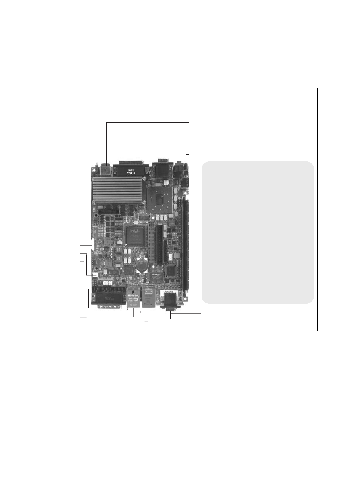
Analog video output connectors
=
= Internal ATA 44-pin connector
= Accessory device power supply
=
= Physical chip for 10/100 LAN controller
= Gigabit LAN controller
=
= System ROM
= Internal
= Heat-sink (processor lies beneath)
=
=
= Super I/O
= Internal USB connector
=
PC/104-Plus (PCI) connector
= Internal ATA 40-pin connector
Internal connector of the parallel interface
South bridge (ICH4)
connector (JTAG)
DIMM slot
North bridge (Intel 855GME)
controller
Battery
= CPU fan connector
A
B
C
D
E
F
G
H
I
J
K
L
M
N
O
P
Q
Matrox 4Sight-M components and connectors
System fan connector
CPU JTAG debugger
LEDs
Power input
Video input connector
2 serial ports
Audio input and output
On/off switch
C
D
P
K
F
G
H
A
B
I
L
M
N
E
DVI-compliant digital VGA connector
J
Gigabit ethernet connector
Ethernet connector
4 USB 2.0 connectors
Auxiliary I/O connector
O
PS/2 connector
Q
MATROX IMAGING est distribué par TECHWAY - www.techway.fr - info@techway.fr - +33 (0)1 64 86 58 30
Page 17

Optional components 17
Memory
Computer memory is provided via a 184-pin DIMM slot, which supports
modules up to 1 Gbyte in size. A 1 Mbyte flash memory device stores the BIOS.
Optional components
You can purchase additional components for Matrox 4Sight-M, which if
purchased, will arrive pre-installed in the integrated unit. A description of each
device is outlined below.
Matrox frame grabbers
You can purchase a Matrox Meteor-II frame grabber for your unit.
Matrox Meteor-II
frame grabbers.
The Matrox Meteor-II frame grabbers capture images and send data to the Host
along the PCI bus. They integrate 4 Mbytes of SGRAM to store the data until
the bus becomes available.
The Matrox Meteor-II frame grabbers are available in four versions in the
PC/104-Plus form factor:
• /Standard. This version captures composite (CVBS) and component (Y/C) video,
in NTSC or PAL format, with square-pixel resolutions.
• /Multi-Channel. This version captures component RGB video, with square-pixel
resolutions.
• /Digital. This version captures digital video with square-pixel resolutions from
digital cameras. Your unit will include a special back-plate that will accommodate
the two digital video inputs ("Digital Video in") connector of the Matrox
Meteor-II /Digital frame grabber.
• /Camera Link. This version captures Camera Link area or line scan video from
monochrome or RGB cameras. Your unit will include a special back-plate that
will accommodate the two Camera Link connectors.
The Matrox Meteor-II /Standard and /Multi-Channel frame grabbers can be made
especially for your Matrox 4Sight-M unit, in that their video input connector can
interface directly with a connector on your unit’s motherboard, which in turn, is
MATROX IMAGING est distribué par TECHWAY - www.techway.fr - info@techway.fr - +33 (0)1 64 86 58 30
Page 18

18 Chapter 1: Before you begin
hardwired to the external video input connector. This allows you to interface your
camera with the frame grabber by connecting it to your unit’s video input
connector. Refer to the Connecting peripherals to the unit chapter for details.
For more information on the Matrox Meteor-II frame grabbers, refer to their
accompanying documentation.
Inspecting your Matrox 4Sight-M package
The following tables indicate standard and optional items included in your Matrox
4Sight-M package. If anything is missing or damaged, contact Matrox.
Integrated-unit version
If you have purchased the integrated-unit version of Matrox 4Sight-M, your
package should include the following items:
Standard package item Details
Integrated unit Encases the following components:
•The motherboard.
• A memory module.
•A storage device.
• A frame grabber (if ordered).
Matrox 4Sight-M software
package
Includes the following:
• An operating system license (if ordered).
• A Matrox 4Sight-M operating system-specific manual.
• The Matrox 4Sight-M CD. The CD contains drivers, utilities, and
applications needed to operate Matrox 4Sight-M.
This Matrox 4Sight-M hardware
and installation reference
Power cord For the power supply interface.
Accessory-device power cable To provide power to certain devices connected to the motherboard.
MATROX IMAGING est distribué par TECHWAY - www.techway.fr - info@techway.fr - +33 (0)1 64 86 58 30
Page 19

Inspecting your Matrox 4Sight-M package 19
Motherboard-only version
If you have purchased the motherboard-only version of Matrox 4Sight-M, your
package should contain the following items:
Standard package item Details
Motherboard
This Matrox 4Sight-M hardware and
installation reference
Matrox 4Sight-M software package Includes the following:
• An operating system license (if a hard drive with an operating
system is ordered).
• A Matrox 4Sight-M software manual.
• A Matrox 4Sight-M CD. The CD contains drivers, utilities, and
applications needed to operate Matrox 4Sight-M.
Accessory-device power cable To provide power to certain devices connected to the
motherboard.
MATROX IMAGING est distribué par TECHWAY - www.techway.fr - info@techway.fr - +33 (0)1 64 86 58 30
Page 20

20 Chapter 1: Before you begin
Additional components
You might have purchased one or more of the following additional components
to complete your unit:
❖ If you have purchased a Matrox Meteor-II /Camera Link frame grabber, you will
need to purchase the Camera Link cables from your camera’s manufacturer or
from 3M Interconnect Solutions for Factory Automation.
Additional component Details
Matrox Imaging software
packages
Refer to the software manual for details on Matrox Imaging software
compatible with Matrox 4Sight-M.
Matrox frame grabbers for
PC-104/Plus
• Matrox Meteor-II/Standard.
• Matrox Meteor-II/Multi-Channel.
• Matrox Meteor-II/Digital (includes the special back-plate to
accommodate the Digital Video input connectors).
• Matrox Meteor-II /Camera Link (includes the special front-plate to
accommodate the two Camera Link connectors).
If purchased with the integrated-unit version of Matrox 4Sight-M, these
devices will be pre-installed in your unit.
Standard 15-pin
VGA-TO-5BNC cable
This cable is used to connect an NTSC/PAL display device to the
secondary analog VGA connector on Matrox 4Sight-M.
DBHD44-TO-13BNC cable Used for interfacing to a Matrox Meteor-II/Standard frame grabber.
Six adapter cables for Y/C input (BNC-TO-SVHS) are shipped with the
DBHD44-TO-13BNC cable.
DBHD44-TO-13BNC/O
cable with a high density
44-pin connector
Also used for interfacing to the Matrox Meteor-II /Standard frame grabber.
This is an open-ended version of the DH44-TO-13BNC cable. It is required
for connection to special input and output signals, such as
synchronization, control, and DC power output.
DBHD44-TO-8BNC cable Used for interfacing to a Matrox Meteor-II /Multi-Channel frame grabber.
Three adapter cables for Y/C input (BNC-TO-SVHS) are shipped with the
DBHD44-TO-8BNC cable.
DBHD44-TO-8BNC/O cable Also used for interfacing to the Matrox Meteor-II /Multi-Channel frame
grabber.
This is an open-ended version of the DBHD44-TO-8BNC cable. It is
required for connection to special input and output signals, such as
synchronization, control, and DC power output.
VHDCI-TO-OPEN cable Used for interfacing to a Matrox Meteor-II /Digital frame grabber.
MATROX IMAGING est distribué par TECHWAY - www.techway.fr - info@techway.fr - +33 (0)1 64 86 58 30
Page 21

Operating your Matrox 4Sight-M unit 21
Operating your Matrox 4Sight-M unit
The following points should be considered when operating your Matrox 4Sight-M
unit.
Light emitting diodes (LEDs)
There are a total of six clearly labelled LEDs on the Matrox 4Sight-M unit.
• On one side, there are four LEDs:
- On (topmost LED). The Power-on LED lights up when the unit is on.
- User (second LED). The User-defined LED is currently teserved for future use.
-Diagnostics (third LED). The Diagnostic LED flashes according to a
pre-determined pattern to communicate POST errors. See the BIOS reference
appendix for details on interpreting the flash codes.
- HDD (bottom LED). The Hard disk drive LED lights when the hard disk is
working.
• On the opposite side, there are four network LEDs:
- 100 Mbps (yellow LED). The 100 Mbps LED light when the networking
interface is in 100BaseT mode. This LED shuts off when the network interface
is in 10BaseT mode.
- Activity (green LED). The Activity LED for the 100 Mbps network interface
lights when the unit is connected to a network and blinks during data transfers;
this LED shuts off when there is no connection present.
- GbE (100/1000 bicolor LED). The Gigabit Ethernet LED lights yellow when
the networking interface is using the 100BaseT Ethernet network connection;
the LED lights green when the networking interface is using the 1000 Gigabit
Ethernet network connection. This LED shuts off when the unit uses the
10BaseT connection.
- Activity (green LED). The Activity LED for the GbE network interface lights
when the unit is connected to a network and blinks during data transfers. This
LED shuts off when there is no connection present.
MATROX IMAGING est distribué par TECHWAY - www.techway.fr - info@techway.fr - +33 (0)1 64 86 58 30
Page 22

22 Chapter 1: Before you begin
Handling precautions
Your Matrox 4Sight-M motherboard is sensitive to static electricity and surges. To
avoid damaging the motherboard, follow these precautions:
Precautions
applicable to both
versions of Matrox
4Sight-M
•Be sure to turn off the power to your unit and all peripherals before adding or
removing devices.
• Don’t touch the heat sinks while the unit is operating; they might be very hot.
• Drain static electricity from your body by touching a metal fixture (or ground)
before touching the motherboard.
• Avoid letting your clothing come in contact with the motherboard.
Precautions
applicable to the
motherboard-only
version.
• Keep the motherboard in its protective bag until you are ready to install it.
• Handle the motherboard by its edges.
Turning off the integrated-unit version of Matrox 4Sight-M
To turn off the integrated-unit version of Matrox 4Sight-M, push and hold the
power button for at least four seconds. While it is being pressed, the unit will
shut-off. This feature acts as a safety precaution so that your unit is less likely to
be turned off by accident.
You can however, reconfigure certain BIOS settings, which will allow you to turn
off the unit by pushing and releasing the power-button immediately.
For information on changing the BIOS settings, refer to BIOS reference.
MATROX IMAGING est distribué par TECHWAY - www.techway.fr - info@techway.fr - +33 (0)1 64 86 58 30
Page 23

Chapter
2
Connecting
peripherals to the
unit
This chapter is geared to users who are ready to connect
various peripherals to their unit
MATROX IMAGING est distribué par TECHWAY - www.techway.fr - info@techway.fr - +33 (0)1 64 86 58 30
Page 24

24 Chapter 2: Connecting peripherals to the unit
Overview
This chapter describes how to connect various devices to the Matrox 4Sight-M
unit.
Important In addition to connecting the devices, some devices must be configured to properly
interact with Matrox 4Sight-M. For information on the configuration procedure,
refer to your operating system-specific, Matrox 4Sight-M software manual.
The front and back panels of Matrox 4Sight-M provide connection to:
• A USB mouse, keyboard, and printer, as well as an additional USB or USB 2.0
device.
• One or two high-resolution monitors.
• An NTSC/PAL video display device, such as a TV monitor.
• A DVI display device (such as a digital flat panel screen).
Front panel
Back panel
Serial
ports
Ethernet jack (top)
and
USB 2.0
connectors (bottom)
analog VGA
connector (top)
and
DVI-compliant
digital VGA
connector (bottom)
Video input
connector
Audio input (top)
and output (bottom)
Power
connector
Auxiliary I/O port
Gigabit Ethernet jack (top)
and
USB 2.0 connectors (bottom)
Power
button
LEDs
MATROX IMAGING est distribué par TECHWAY - www.techway.fr - info@techway.fr - +33 (0)1 64 86 58 30
Page 25

Connecting display devices 25
• A local area network (LAN) at 10/100 Mbps.
• A Gigabit Ethernet interface at 10/100/1000 Mbps
• A video input device.
• A serial device (2 connectors).
• External devices that connect to the auxiliary I/O interface.
• A stereo audio device.
Connecting display devices
Connect a high-resolution monitor or analog flat panel to analog VGA
connector #1, or a digital flat panel to the DVI-compliant digital VGA connector
("DVI-I"). You can also connect a TV or a second high-resolution display (such
as, another monitor or analog flat panel) to analog VGA connector #2.
The various display combination options are presented below:
Devices connected to analog VGA connector Devices connected to the TV-Out/DVI-I connector
standard high-resolution monitor
NC
1
1. “NC” = no connection.
* Using a DVI to VGA adapter.
standard high-resolution monitor standard high-resolution monitor*
standard high-resolution monitor analog flat panel*
standard high-resolution monitor digital flat panel
standard high-resolution monitor TV (NTSC or PAL)
analog flat panel NC
analog flat panel standard high-resolution monitor
analog flat panel analog flat panel
analog flat panel TV (NTSC or PAL)
NC standard high-resolution monitor*
NC analog flat panel*
NC digital flat panel
NC TV (NTSC or PAL)
MATROX IMAGING est distribué par TECHWAY - www.techway.fr - info@techway.fr - +33 (0)1 64 86 58 30
Page 26
26 Chapter 2: Connecting peripherals to the unit
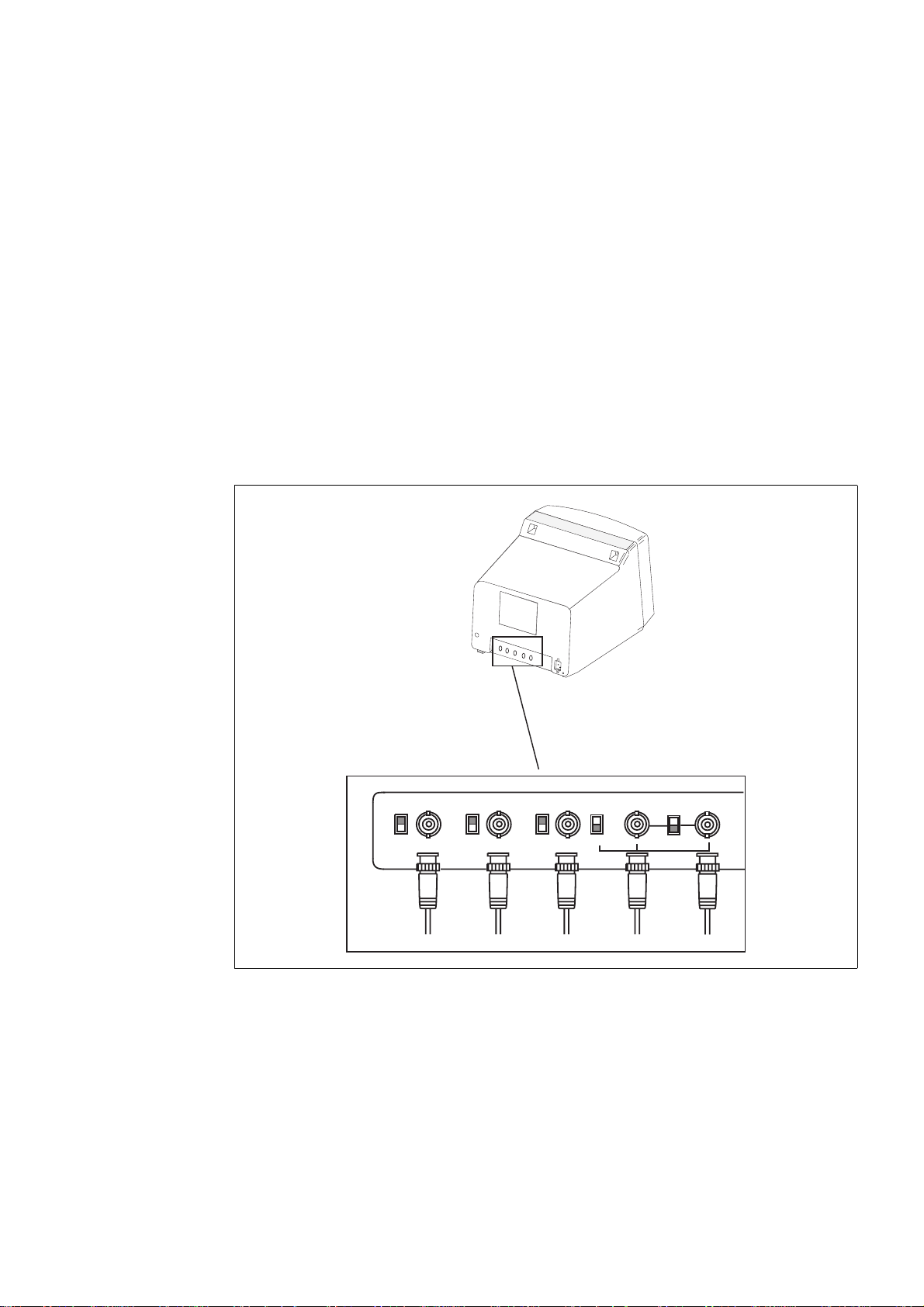
Connecting a high-resolution display device
To connect your high-resolution monitor(s):
1. Connect the first monitor to the top analog VGA connector (connector #1) on
the Matrox 4Sight-M unit. If your monitor has a DB-15 connector, use a standard
DB-15 to DB-15 cable. If your monitor has 5 BNC-type connectors, use a
standard DB-15 to 5-BNC cable. To connect your monitor with a DB-15 to
5-BNC, refer to steps 2 and 3. These cables are usually supplied with your monitor.
2. If your monitor has input impedance switches, set the switches for the red, green,
and blue inputs to 75 ohms, as shown in the illustration below.
3. Set the switches for the synchronization inputs according to your monitor’s
manual. In most cases, these switches should be set to high impedance and external
synchronization mode.
G
R
B
HSYNC
VSYNC
(BNC)
(BNC) (BNC)
(BNC)
(BNC)
INT
EXT
75757575
RED BLUE
GREEN
WHITE
or
GRAY
BLACK
MATROX IMAGING est distribué par TECHWAY - www.techway.fr - info@techway.fr - +33 (0)1 64 86 58 30
Page 27

Connecting display devices 27
4. If you have a second high-resolution monitor, you can connect it to the
TV-Out/DVI-I connector (connector #2) on the Matrox 4Sight-M unit. Connect
the DVI-to-VGA adapter (provided wtih the Matrox 4Sight-M unit) to the
TV-Out/DVI-I connector.
5. Follow the same procedures as outlined in the above steps for connecting the first
high-resolution monitor to the first VGA connector.
Connecting a digital flat panel
Connect a digital flat-panel to the DVI-compliant digital VGA connector
("DVI-I") using the cable provided with your display device.
Connecting NTSC/PAL video output devices
You can connect video output devices, such as a TV monitor or VCR to analog
VGA connector #2. Matrox 4Sight-M can output both composite (CVBS) and
component (Y/C) video in NTSC or PAL format. It can also output component
RGB video with resolutions similar to video in NTSC/PAL formats.
Connect the DVI-to-VGA adapter to the VGA connector #2, then connect your
device to analog VGA connector #2, using a DB-15 to 5BNC adapter cable,
composed of a 15-pin VGA connector on one side, and 5 BNC connectors on the
other. This cable can be purchased from various third-party vendors. The wires
of the BNC connectors are color-coded for the following output:
To output video to an NTSC/PAL video output device, configure your unit using
the appropriate commands when programming your imaging application. Refer
to your imaging software’s documentation for details.
Wire Analog composite video output Analog Y/C video output Analog RGB video output
Green Luma
Y G
Red
Chroma C R
Blue Encoded CVBS (composite
signals)
CVBS B
Black Not connected
Composite sync
Composite sync
1
1. Note that the synchronization signal can have its own line, or be coupled with either the R, G, or B signal.
Gray Not connected
Not connected Not connected
MATROX IMAGING est distribué par TECHWAY - www.techway.fr - info@techway.fr - +33 (0)1 64 86 58 30
Page 28

28 Chapter 2: Connecting peripherals to the unit
Connecting a USB mouse, keyboard, or printer
You can connect any USB-compliant mouse, keyboard, or printer to the USB
connectors, located on the front panel of the Matrox 4Sight-M unit.
Connecting other USB devices
If you are using Matrox 4Sight-M under the Microsoft Windows 2000 or
Windows XP operating system, you can connect other USB devices to the USB
connectors.
If you are using another operating system, refer to its accompanying
documentation to determine if USB devices are supported.
Networking connections
Connect a network cable to an Ethernet jack, located on the front panel of the
chassis.
Required cabling for
Ethernet
connections
Matrox 4Sight-M can gain access to a LAN via Fast Ethernet (100BaseT) or
Twisted Pair Ethernet (10BaseT) through the 10/100BaseT Ethernet jack. You
can also use a Gigabit Ethernet interface connection through the Gigabit Ethernet
jack.
If you plan to use Fast Ethernet, use an Unshielded Twisted Pair Category 5
(UTP5) cable. If you will be using Twisted Pair Ethernet, use a UTP5 or UTP3
cable. If you plan to use Gigabit Ethernet, use a Category 5e (CAT5e) cable.
MATROX IMAGING est distribué par TECHWAY - www.techway.fr - info@techway.fr - +33 (0)1 64 86 58 30
Page 29
Networking connections 29
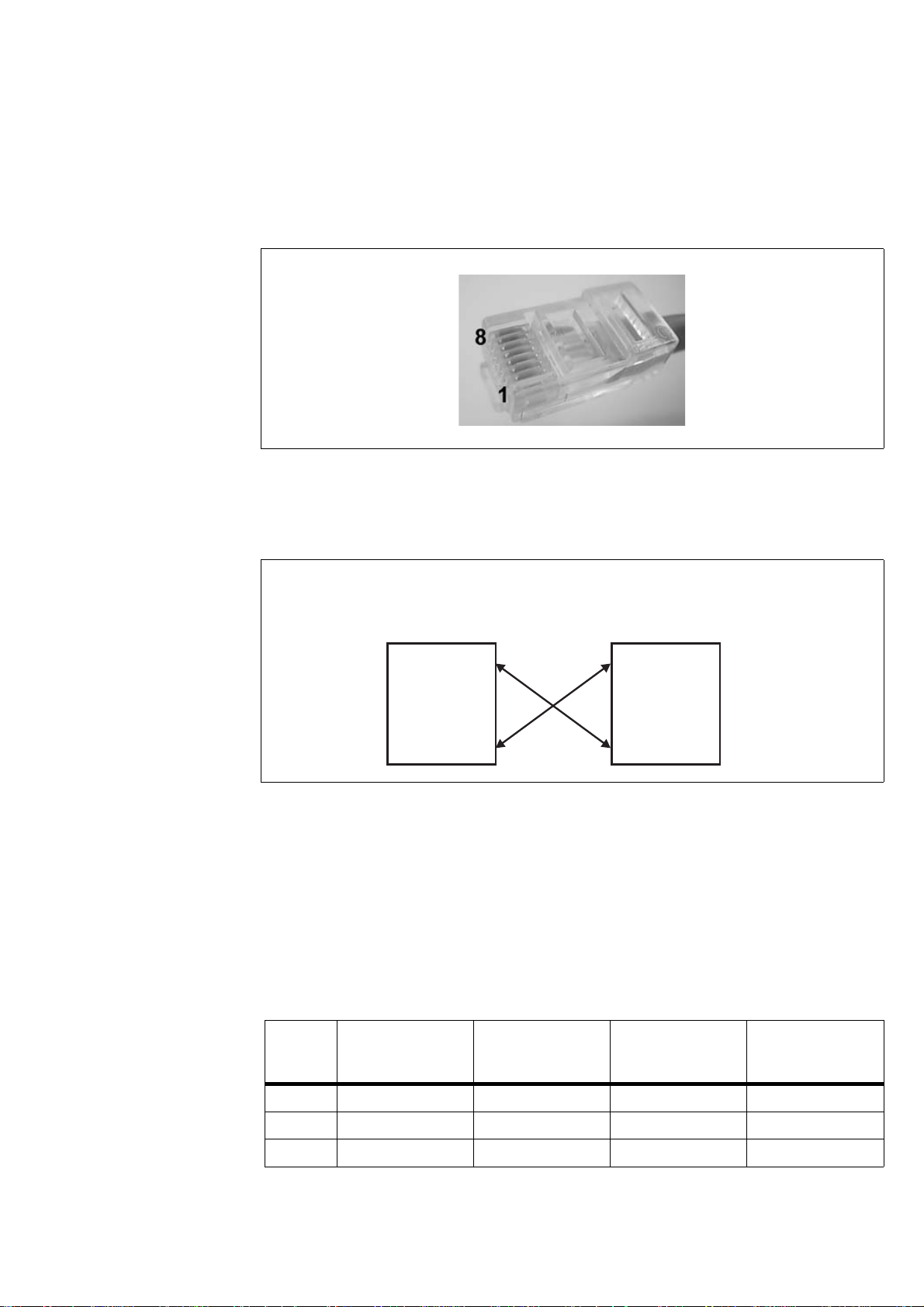
An RJ45 connector must be attached to each end of the cable.
Peer-to-peer
communication
To connect the Matrox 4Sight-M unit in a peer-to-peer communication
configuration, you will have to use a custom-made crossover network cable to
connect your unit and the computer.
Build this special cable based on the following table, using an Unshielded Twisted
Pair Category 5 (UTP5) cable. An RJ45 connector must be attached to each end
of the crossover cable.
❖ This special peer-to-peer cable is only used for the 10/100 Ethernet jack.
Connect the wires of the cable as follows. Each row in the table represents a wire
of the cable:
RJ45 Left-side
function
Left-side RJ45
cable-connector
pin-number
Right-side RJ45
cable- connector
pin-number
RJ45 Right-side
function
Wire 1 TX+ 1 3 RX+
Wire 2TX-26RX-
Wire 3 RX+ 3 1 TX+
Peer-to-peer connection for Matrox 4Sight-M.
PC 1
Matrox 4Sight-M
Transmitter
Receiver
Transmitter
Receiver
MATROX IMAGING est distribué par TECHWAY - www.techway.fr - info@techway.fr - +33 (0)1 64 86 58 30
Page 30

30 Chapter 2: Connecting peripherals to the unit
Connecting video input devices
Most Matrox frame grabbers designed for Matrox 4Sight-M have a custom video
input connector that attaches directly to the motherboard, which in turn, is
hard-wired to the video input connector, on the back side of the unit. Therefore,
you can interface a camera with the frame grabber by connecting the camera to
your unit’s video input connector.
Two exceptions to this are Matrox Meteor-II /Digital and Meteor-II /Camera Link
for PC/104-Plus:
• You must connect video sources to Matrox Meteor-II /Digital through the frame
grabber’s two digital video input connectors, Digial Video in 1 and 2, located on
the back side of the unit.
• Yo u m us t co nn ec t vi de o s ou rc es to Ma tr ox Me te or -I I / Ca me ra Li nk to the Ca me ra
Link input connectors, located on the back side of the unit.
Note that if you purchase additional frame grabbers for your unit, the video input
connector of your frame grabber will not interface directly with the motherboard.
Therefore, you will have to connect your cameras directly to the additional frame
grabbers. Refer to Chapter 3: Adding devices to the Matrox 4Sight-M motherboard
for information on installing additional frame grabbers to your unit, and refer to
your frame grabber’s installation guide for cabling and pinout information.
Units with a Matrox Meteor-II /Standard
A DBHD44-TO-13BNC cable is used to interface video sources through Matrox
4Sight-M’s video input connector to a Matrox Meteor-II /Standard frame grabber
(designed for Matrox 4Sight-M).
Wire 4BD1+47BD2+
Wire 5BD1-58BD2-
Wire 6 RX- 6 2 TX-
Wire 7BD2+74BD1+
Wire 8BD2-85BD1-
RJ45 Left-side
function
Left-side RJ45
cable-connector
pin-number
Right-side RJ45
cable- connector
pin-number
RJ45 Right-side
function
MATROX IMAGING est distribué par TECHWAY - www.techway.fr - info@techway.fr - +33 (0)1 64 86 58 30
Page 31

Connecting video input devices 31
This cable has a DBHD44 connector on one side, and thirteen BNC connectors
on the other. It supports up to twelve video input signals and one trigger signal.
The thirteen BNC wires connect to the different cameras, as such:
Connecting to
composite input
signals
You can interface up to twelve composite cameras to Matrox Meteor-II /Standard
on the 4Sight-M. To do so:
1. Connect each camera to one of the BNC wires, using the information in the
previous table.
2. Attach the DBHD44 connector to "Video in", the video input connector of
Matrox 4Sight-M.
BNC#
1
Signal Composite camera input connector Y/C camera input connector
1 VID_IN1 Camera 1 Y (camera 1)
2 VID_IN2 Camera 2 C (camera 1)
3 VID_IN3 Camera 3 Y (camera 2)
4 VID_IN4 Camera 4 C (camera 2)
5 VID_IN5 Camera 5 C (camera 4)
6 VID_IN6 Camera 6 Y (camera 3)
7 VID_IN7 Camera 7 C (camera 3)
8 VID_IN8 Camera 8 Y (camera 4)
9 VID_IN9 Camera 9 Y (camera 5)
10 VID_IN10 Camera 10 C (camera 5)
11 VID_IN11 Camera 11 Y (camera 6)
12 VID_IN12 Camera 12 C (camera 6)
13 OPTOTRIG
External trigger input (OPTOTRIG+)
2
External trigger input (OPTOTRIG+)
2
1. The wire color associated with each BNC number can be found on the color code pinout char t included with the
DBHD44-TO-13BNC cable.
2. OPTOTRIG- is connected to the ground of the trigger source, and passes through the cable shield.
MATROX IMAGING est distribué par TECHWAY - www.techway.fr - info@techway.fr - +33 (0)1 64 86 58 30
Page 32

32 Chapter 2: Connecting peripherals to the unit
3. Attach the DBHD44 connector to the video input connector of Matrox 4Sight-M.
Connecting to other
signals
You can also use a DBHD44-TO-13BNC/O cable if you need to interface other
signals (such as, special user input and output signals) in addition to composite
and Y/C video signals. The DBHD44-TO-13BNC/O cable is an open-ended
version of the DH44-TO-13BNC cable. The pinout of the video input connector,
found in Technical reference, contains a list of all the signals available along the
interface. After referring to this table, you can then refer to the color code pinout
chart, included with your cable, to connect the appropriate wire.
Units with Matrox Meteor-II /Multi-Channel
To interface video sources to a Matrox Meteor-II /Multi-Channel frame grabber
(designed for Matrox 4Sight-M), use a DBHD44-TO-8BNC cable to connect to
the unit’s external video input connector.
This cable has a DBHD44 connector on one side, and eight BNC connectors on
the other. It supports up to seven video input signals and one trigger signal.
The wires of this cable are numbered as follows:
Connecting to RGB
input signals
You can interface up to two RGB cameras to the Matrox Meteor-II
/Multi-Channel frame grabber. To do so:
1. Connect the BNC wires to each RGB camera using the information from the
above table.
2. Attach the DBHD44 connector to the video input connector of Matrox 4Sight-M.
BNC #
1
Signal RGB camera input connector
1 VID1_IN1 R (camera 1)
2 VID1_IN2 G (camera 1)
3 VID1_IN3 B (camera 1)
4 SYNC_IN SYNC
5OPTOTRIG
External trigger input (OPTOTRIG+)
2
6 VID2_IN1 R (camera 2)
7 VID2_IN2 G (camera 2)
8 VID2_IN3 B (camera 2)
1. The wire color associated with each BNC number can be found on the color code pinout chart included with the
DBHD44-TO-8BNC cable.
2. OPTOTRIG- is connected to the ground of the trigger source, and passes through the cable shield.
MATROX IMAGING est distribué par TECHWAY - www.techway.fr - info@techway.fr - +33 (0)1 64 86 58 30
Page 33

Connecting video input devices 33
Connecting to other
signals
You can also use a DBHD44-TO-8BNC/O cable if you need to connect to other
signals (such as, special user input and output signals) in addition to RGB video
signals. The DBHD44-TO-8BNC/O cable is an open-ended version of the
DH44-TO-8BNC cable.
Units with Matrox Meteor-II /Digital
To interface video sources to a Matrox Meteor-II /Digital frame grabber (designed
for Matrox 4Sight-M), use one or two VHDCI-TO-OPEN cables to connect to
the unit’s digital video input connectors. These cables have a VHDCI connector
on one side, and are open-ended on the other.
Connecting to digital
input signals
You can interface digital video sources to Matrox Meteor-II /Digital. To do so:
1. Refer to the Technical reference appendix, for the pinout of the digital video input
connectors on Matrox 4Sight-M.
2. Attach the open-ended side of the cable to connectors designed to interface with
your cameras, and connect them to the cameras.
3. Attach the VHDCI connector to the digital video input connector "Digial video
in 1" of Matrox 4Sight-M
1
.
4. Repeat the previous steps if you need to connect additional cameras to the bottom
digital video input connector.
Units with Matrox Meteor-II /Camera Link
To interface video sources to Matrox Meteor-II /Camera Link, simply attach your
cables to the Camera Link connectors on the Matrox 4Sight-M unit.
Connecting to other
signals
Other signals, such as special user input and output signals, can be accessed
through the 44-pin video input ("Video in") connector of Matrox 4Sight-M. The
pinout of the video input connector, found in the Technical reference appendix,
contains a list of all the signals available for the interface. For customers planning
to build their own cable, parts can be purchased from:
1. A single camera might require interfacing to both digital video input connectors if its
image acquisition format uses 3 x 8-bit, 2 x 16-bit, or 1 x 32-bit configurations.
Manufacturer NorComp Interconnect Devices
Connector HDT44P
MATROX IMAGING est distribué par TECHWAY - www.techway.fr - info@techway.fr - +33 (0)1 64 86 58 30
Page 34

34 Chapter 2: Connecting peripherals to the unit
Connecting devices to the serial port
You can connect devices to the two serial ports using a 9-pin RS-232 or
RS-422/RS-485 serial port cable.
If you connect RS-422/RS-485 serial devices, remember to configure the serial
port to meet this standard. This is done by adjusting the internal dip switch.
Note that the RS-422/RS-485 standard cables are different from those meeting
the RS-232 standard. This is because RS-422/RS-485 specifies differential
signaling, and therefore its electrical requirements are different. In addition, the
function of the serial port connector’s pins are different when operating under
RS-422/RS-485. For details on the connector pinout of each interface, refer to
the Technical reference appendix.
Connecting devices to the auxiliary I/O interface
If you have purchased the integrated-unit version of Matrox 4Sight-M, you can
connect devices to the auxiliary I/O interface connector, located on the front panel
of the unit.
The auxiliary I/O interface supports up to 24 V. Each input can be driven by TTL
devices or other devices, up to a maximum of 24 V. Each output is capable of
sinking up to 100 mA (fuse protected) with a voltage up to 24 V. Auxiliary output
signals are only capable of sinking currents (using only the sink driver), that is,
auxiliary outputs are not capable of sourcing voltage. Essentially, instead of
transmitting a high or low voltage state, a current from a connected device is either
terminated (grounded) or not.
Connecting TTL
devices
To connect TTL devices to the external auxiliary I/O interface connector, you will
need a custom cable with a DBHD44 connector.
Pinout information for the auxiliary I/O connector can be found in the Technical
reference appendix. You can also refer to this appendix for information on where
a custom-mating connector can be obtained.
MATROX IMAGING est distribué par TECHWAY - www.techway.fr - info@techway.fr - +33 (0)1 64 86 58 30
Page 35

Connecting a stereo audio device 35
The output of a TTL device can be connected directly to an input on the auxiliary
I/O. The input of a TTL device can be connected directly to an output on the
auxiliary I/O; however, you will need to add a pull-up resistor to this connection
(connected at 5 V).
Connecting non-TTL
devices
The output of a non-TTL device (up to a maximum of 24 V) can be connected
directly to an input on the auxiliary I/O. The input of a non-TTL device can be
connected directly to an output on the auxiliary I/O. You might need to add a
pull-up resistor to this connection (connected at 5 V). Refer to the vendor
specifications for your non-TTL device for more information.
To connect non-TTL devices to the external auxiliary I/O interface connector,
you need a custom cable with a DBHD44 connector.
Important Voltage requirements for external devices connected to the auxiliary connector
module should not exceed 24 V.
Connecting a stereo audio device
You can connect a stereo audio device to the audio input and output jacks, using
a 1/8” mini audio input/output plug. The audio interface is only designed for line
input/output operations. Because there is no output amplifier or input
preamplifier, the interface will not support speakers nor microphones.
MATROX IMAGING est distribué par TECHWAY - www.techway.fr - info@techway.fr - +33 (0)1 64 86 58 30
Page 36

36 Chapter 2: Connecting peripherals to the unit
MATROX IMAGING est distribué par TECHWAY - www.techway.fr - info@techway.fr - +33 (0)1 64 86 58 30
Page 37

Part 2: Customizing
the motherboard
MATROX IMAGING est distribué par TECHWAY - www.techway.fr - info@techway.fr - +33 (0)1 64 86 58 30
Page 38

MATROX IMAGING est distribué par TECHWAY - www.techway.fr - info@techway.fr - +33 (0)1 64 86 58 30
Page 39

Chapter
3
Adding devices to
the Matrox 4Sight-M
motherboard
This chapter deals with additions that can be made to the
Matrox 4Sight-M motherboard.
MATROX IMAGING est distribué par TECHWAY - www.techway.fr - info@techway.fr - +33 (0)1 64 86 58 30
Page 40

40 Chapter 3: Adding devices to the Matrox 4Sight-M motherboard
Introduction
The Matrox 4Sight-M integrated unit is designed to accommodate selected
hardware additions. The following diagram provides a reference to motherboard
connections:
If you have purchased the integrated-unit version of Matrox 4Sight-M, the first
step in making hardware additions involves removing the chassis cover. Once
removed, you will have access to all the connectors located on the motherboard.
The following sections outline how to remove the chassis cover, as well as how to
connect various IDE devices, PC/104-Plus boards, memory modules, parallel
devices, and external devices that connect to the auxiliary I/O interface.
DIMM slot
Internal
ATA 44-pin connector
Back Panel
Front Panel
Internal connector of
the parallel interface
Internal ATA 40-pin connector
PC/104expansion site
Plus
TM
MATROX IMAGING est distribué par TECHWAY - www.techway.fr - info@techway.fr - +33 (0)1 64 86 58 30
Page 41

Removing the Matrox 4Sight-M chassis 41
Removing the Matrox 4Sight-M chassis
To remove the Matrox 4Sight-M chassis:
Warning 1. Unplug the Matrox 4Sight-M power cord.
2. Remove the appropriate screws and nut on the Matrox 4Sight-M unit’s front panel.
3. With the Matrox 4Sight-M unit laid flat, face the back panel, place your hands
on top of the chassis and slowly slide the chassis so that the top and front panels
(which are attached) separate from the back and bottom panels (which are also
attached).
Front panel
remove this
screw
remove this
screw
remove these nuts
remove these nuts
Back panel
MATROX IMAGING est distribué par TECHWAY - www.techway.fr - info@techway.fr - +33 (0)1 64 86 58 30
Page 42

42 Chapter 3: Adding devices to the Matrox 4Sight-M motherboard
Warning Do not touch the heat sinks while the unit is running, or soon after it has been
turned off; they might be very hot.
Warning If your Matrox 4Sight-M unit is installed in a factory-provided chassis, be sure to
always operate it with the cover on. This ensures that the fan properly removes
any heat accumulating in the heat sinks.
If you have one or more devices connected to the motherboard, it might be
impossible to properly place the cover on top of the chassis. One way to work
around this is to flip and install the cover so that the front panel points upwards.
This will avoid interference from any cables or devices that are coming out of the
chassis.
MATROX IMAGING est distribué par TECHWAY - www.techway.fr - info@techway.fr - +33 (0)1 64 86 58 30
Page 43

Connecting a hard disk or CD drive 43
Connecting a hard disk or CD drive
The Matrox 4Sight-M motherboard provides a primary ATA 44-pin connector
and a secondary ATA 40-pin connector, each of which allows you to connect one
or two IDE devices. The location of the ATA connectors are shown in the diagram
below:
The following sections outline the procedure to be followed when connecting IDE
devices to your unit.
Connecting devices with an ATA 44-pin connector
You can connect one IDE device that has an ATA 44-pin connector (such as 2.5
inch hard disk) to the ATA 44-pin internal connector. To do so, use a flat ribbon
cable with a 44-pin, IDC, female connector on each side.
If you need to connect two ATA 44-pin connector, IDE devices to a single
ATA 44-pin connector, you will have to make a custom cable. For pinout
information, refer to the Technical reference appendis.
Secondary ATA 40-pin connector
Front Panel
Power-supply connector
to IDE device
Primary ATA 44-pin
connector
MATROX IMAGING est distribué par TECHWAY - www.techway.fr - info@techway.fr - +33 (0)1 64 86 58 30
Page 44

44 Chapter 3: Adding devices to the Matrox 4Sight-M motherboard
Connecting devices with an ATA 40-pin connector
You can connect one IDE device that has an ATA 40-pin connector (such as a CD
drive or a 3.5 inch hard disk) to the secondary connector.
Connecting one IDE
device
If you want to connect one IDE device that has an ATA 40-pin connector to the
ATA 40-pin connector, you will need the following items:
• A flat-ribbon cable with 40-pin, IDC, female connectors on each side.
• An accessory power cable (included with your Matrox 4Sight-M package).
To connect the device:
1. Attach a 40-pin connector of the flat-ribbon cable to the ATA 40-pin connector
on the device.
2. Attach the other end of the flat-ribbon cable to the secondary ATA 40-pin
connector.
3. Attach the accessory power cable between the power-input connector on your IDE
device, and the power-supply connector on the motherboard.
Important The voltages that can be drawn from the 4-pin power supply connector on the
motherboard are outlined in the Motherboard section of the Technical reference
appendix. If the IDE device that you are connecting requires more power than
that specified in the table, use an external power supply. If you do not, you will
risk damaging the motherboard.
Connecting two IDE
devices to a single
ATA 40-pin
connector
If you want to connect two, 40-pin connector, IDE devices to the secondary
ATA 40-pin connector, you will need the following items:
• A flat-ribbon cable with three 40-pin, IDC, female connectors at each end.
• A custom power cable. The accessory power cable provided by Matrox will not be
adequate, since it has been designed for use by a single device only.
MATROX IMAGING est distribué par TECHWAY - www.techway.fr - info@techway.fr - +33 (0)1 64 86 58 30
Page 45

Connecting a hard disk or CD drive 45
To connect the devices:
1. Using the three-connector flat-ribbon cable, attach one connector to the
motherboard, and attach the other two connectors to each device.
2. Set the jumpers on each device, so that one will operate in master mode, and the
other in slave mode.
3. Attach the custom power cable between the power-input connectors on your IDE
devices, and the power-supply connector on the motherboard.
Important The voltages that can be drawn from the 4-pin power connector on the
motherboard are outlined in the Motherboard section of the Technical reference
appendix. If the IDE device you are connecting requires more power than that
specified in the table, use an external power supply. If you do not, you will risk
damaging the motherboard.
Connecting both types of IDE devices
You can connect both types of IDE devices to the motherboard simultaneously.
Follow the procedures outlined in the previous sections.
Drive assignments
By default, if a device is attached to the primary ATA 44-pin connector, it is
automatically identified as the primary master or primary slave by the BIOS.
Similarly, when a device is attached to the secondary ATA 40-pin connector, it
will be identified as the secondary master or secondary slave by the BIOS. Run
the BIOS Setup program to verify your devices’ configurations.
Master or slave designations are based on your device’s jumper settings, and are
used simply to differentiate between two devices connected to the same
ATA 40-pin or ATA 44-pin connector. There is no difference in performance
between these modes. For more information, refer to your device’s documentation.
MATROX IMAGING est distribué par TECHWAY - www.techway.fr - info@techway.fr - +33 (0)1 64 86 58 30
Page 46

46 Chapter 3: Adding devices to the Matrox 4Sight-M motherboard
Connecting a PC/104-Plus board
You can connect up to three PC/104-Plus boards on the Matrox 4Sight-M
motherboard, in a stack-through configuration, as shown below. Each board must
be attached to the other through four jack screws.
Some considerations
The following points are critical when connecting additional PC/104-Plus boards
to the Matrox 4Sight-M motherboard:
• The voltage I/O pins on the Matrox 4Sight-M PC/104-Plus connectors are set to
3.3 V.
Warning • Matrox 4Sight-M cannot tolerate all PC/104-Plus connections. Use only
PC/104-Plus with 3.3 V signalling.
• Matrox 4Sight-M does not support PC/104 ISA boards.
PC/104- boardPlus
module 1
PC/104-
(PCI) connector
Plus
Matrox 4Sight-M motherboard
PC/104- boardPlus
PC/104- boardPlus
module 2
module 3
Connect jack-screws
together.
Fit jack-screws inside
appropriate holes.
Top-most board fitted
with top-screws
MATROX IMAGING est distribué par TECHWAY - www.techway.fr - info@techway.fr - +33 (0)1 64 86 58 30
Page 47

Removing and installing memory 47
•The PC/104-Plus board might have a PCI shroud, a plastic case that protects the
PCI connector pins. However, it hinders air circulation, and therefore should be
removed before installation.
Number of boards • Although it is possible to connect one or more acquisition boards, the actual
number depends on the type of the required frame grabbers. For example, you
can connect up to three Matrox Meteor-II frame grabbers or third-party
PC/104-Plus boards.
Switch positions • You must configure multiple master-capable or interrupt-capable PC/104-Plus
boards using their rotary switch; the rotary switch selects a specific PCI signal.
It is recommended that you configure the first module installed (the module
closest to the motherboard) to 0, the second to 1, and so on. If you are installing
more than one PC/104-Plus
board, the rotary switch on each board must be set
as follows:
Using multiple
acquisition boards
• You can simultaneously grab images from cameras attached to different frame
grabbers. To grab at exactly the same time, the cameras must be genlocked
(synchronized) and their camera definition formats (DCF) must be the same.
Removing and installing memory
The Matrox 4Sight-M motherboard features one 184-pin DIMM slot. This slot
can support DDR SDRAM modules up to 1 Gbyte in size. Matrox 4Sight-M
supports 3.3 V, unbuffered, PC2700-compliant DDR SDRAM DIMMs. This
section describes how to remove and install a DDR SDRAM module.
Removing memory
To remove memory:
1. Spread the clips at each end of the module.
2. Lift the module out of the slot.
Module # Switch position
10 or 4
21 or 5
32 or 6
MATROX IMAGING est distribué par TECHWAY - www.techway.fr - info@techway.fr - +33 (0)1 64 86 58 30
Page 48

48 Chapter 3: Adding devices to the Matrox 4Sight-M motherboard
Installing memory
To insta l l m e m o r y :
1. Ensure that the clips at each end of the module are spread.
2. Position the module over the DIMM slot, such that the notches along the module’s
bottom edge align with the notch in the DIMM slot.
3. Gently insert the bottom edge of the module into the slot.
4. Carefully close the clips over the side notch.
Adjusting your new memory settings
If the Matrox Imaging Library (MIL) or one of its derivatives is installed in your
unit, you must adjust your unit’s new memory settings using MilConfig (the MIL
Configuration utility). Refer to the software manual for more information on
using this utility.
DDR SDRAM module
clip
DIMM slot
notches
MATROX IMAGING est distribué par TECHWAY - www.techway.fr - info@techway.fr - +33 (0)1 64 86 58 30
Page 49

Chapter
4
Installing the
Matrox 4Sight-M
motherboard in a
custom chassis
This chapter provides some guidelines for installing the
Matrox 4Sight-M motherboard in a custom chassis.
MATROX IMAGING est distribué par TECHWAY - www.techway.fr - info@techway.fr - +33 (0)1 64 86 58 30
Page 50

50 Chapter 4: Installing the Matrox 4Sight-M motherboard in a custom chassis
Overview
This chapter provides general guidelines when using a custom chassis to house the
Matrox 4Sight-M motherboard. It also lists specifications to safely connect a
custom power-supply and fan. In addition to this chapter, any specific instructions
included with your custom components should also be read.
If you purchased the Matrox 4Sight-M integrated unit, you can skip this chapter.
Warning To protect the Matrox 4Sight-M motherboard against static electricity, follow the
precautions mentioned in Handling precautions, found in Chapter 1.
Custom chassis
The Matrox 4Sight-M motherboard complies with the EBX form factor
(5.75" x 8").
Make sure the chassis provides clearance for all motherboard components,
particularly the DDR SDRAM module and any PC/104-Plus boards. Also ensure
that there are adequate ventilation openings near the fan and the processor.
To avoid injury, be careful of sharp corners and rough edges when mounting the
chassis.
MATROX IMAGING est distribué par TECHWAY - www.techway.fr - info@techway.fr - +33 (0)1 64 86 58 30
Page 51

Custom fan 51
Custom fan
You can use any fan that provides at least 18 cfm (0.5 m3/min.) of air flow through
the CPU heat sink. Due to the heat sink’s convoluted fins, the fan must be placed
on one side of the heat sink, as illustrated in the diagram below. This will ensure
proper airflow through the fins, resulting in an efficient removal of accumulated
heat.
The following are the specifications for each pin on the fan connector:
Pin Power supply (V) Max. voltage (V) Min. voltage (V) Max. current (A)
1GROUND
27-12 12 7 0.5
3 Tachometer, four pulses per rotation.
Front Panel
System fan connector
Place fan on either side of the motherboard
heat sink
MATROX IMAGING est distribué par TECHWAY - www.techway.fr - info@techway.fr - +33 (0)1 64 86 58 30
Page 52

52 Chapter 4: Installing the Matrox 4Sight-M motherboard in a custom chassis
Custom power supply
The power connector on the stand-alone Matrox 4Sight-M motherboard is a 4-pin
locking connector.
Voltage requirements for each pin are given below.
Pin Power supply (V) Max. voltage (V) Min. voltage (V)
Maximum current
1
(A)
1. The maximum current capacity of each pin is 7 A.
1 12-24 24 12 7
2GROUND
3 12-24 24 12 7
4GROUND
Rear of motherboard
Pin 1 Pin 2
Pin 3 Pin 4
MATROX IMAGING est distribué par TECHWAY - www.techway.fr - info@techway.fr - +33 (0)1 64 86 58 30
Page 53

Part 3: Reference
material for all
users
MATROX IMAGING est distribué par TECHWAY - www.techway.fr - info@techway.fr - +33 (0)1 64 86 58 30
Page 54

MATROX IMAGING est distribué par TECHWAY - www.techway.fr - info@techway.fr - +33 (0)1 64 86 58 30
Page 55

Chapter
5
Matrox 4Sight-M
hardware reference
This chapter provides hardware descriptions of
Matrox 4Sight-M.
MATROX IMAGING est distribué par TECHWAY - www.techway.fr - info@techway.fr - +33 (0)1 64 86 58 30
Page 56

56 Chapter 5: Matrox 4Sight-M hardware reference
Overview
The hardware reference provides a detailed description of the major components
making up Matrox 4Sight-M. Technical information, such as connector pinouts
and hardware specifications can be found in Technical reference.
Motherboard
The Matrox 4Sight-M EBX motherboard integrates processing, display, storage,
networking, and I/O functionality. EBX is a standard form factor with a small
footprint (8” x 5¾”).
Intel
North Bridge (GMCH)
855 GME
with integrated graphics
®
Embedded
Intel
Celeron M or
TM
®
®
Pentium M
64 at 400 MHz FSB
/
Intel ICH4
(82801DB)
®
Hub interface
266 Mbytes/s
IDE
Hard drive
4 channel
USB 2.0
AC'97
2.2/2.3
Ethernet
PHY
10/100 Mb
up to
1 Gbyte of
DDR
SDRAM
(333 Mhz)
VGA1
DVO
Chrontel
7009
encoder
VGA2
TV-OUT
DVI
/
Super I/O
controller
User I/O
FPGA
PCI 32 bits/33 Mhz
User I/O
Watchdog
COM1
COM2
PP
PS/2
Matrox Imaging
Frame Grabber
Matrox Imaging
Frame Grabber
Gigabit
Ethernet
Fan
Controller
LPC Bus
MATROX IMAGING est distribué par TECHWAY - www.techway.fr - info@techway.fr - +33 (0)1 64 86 58 30
Page 57

Processing 57
Processing
Microprocessor The Matrox 4Sight-M motherboard supports either the Intel Celeron M
microprocessor, running at 1.3 GHz, or an Intel Pentium M microprocessor,
running at 1.6 GHz.
Chipset The chipset consists of the Intel 855GME graphics and memory hub controller
(GMCH) and the Intel ICH4 I/O hub controller (ICH).
The Intel 855GME components include:
• A Host interface that transfers data between the processor, computer memory,
and peripherals at a rate of 400 MHz.
• A computer memory (DRAM) controller, which can support a 64-bit DIMM
main memory interface, running at up to 333 Mhz.
The Intel ICH4 components include:
• A PCI interface, which can transfer data over the 32-bit PCI bus at rates up to
133 Mbytes/sec.
• An EIDE controller, working in UltraDMA-33/66/100 master mode.
• A USB 2.0 controller.
• A RealTime clock.
• A LAN controller 10/100 Mbits/sec.
• A digital audio controller.
• Power management features.
The Intel ICH4 interfaces with the BIOS, via a LPC bus. In addition, it interfaces
with the 855GME GMCH via the hub link (version 1.5) interface at 266
Mbytes/sec.
MATROX IMAGING est distribué par TECHWAY - www.techway.fr - info@techway.fr - +33 (0)1 64 86 58 30
Page 58

58 Chapter 5: Matrox 4Sight-M hardware reference
MMX and SSE
technology
The Intel Celeron M and Intel Pentium M processors both use multimedia
extension (MMX) technology. This technology, an extension to the Intel
architecture, is designed specifically to accelerate multimedia and imaging
applications. It addresses the key characteristics of applications that must handle
large amounts of image, video, and graphics data.
The Intel Celeron M and Intel Pentium M processors also use single SIMD
extension (SSE) technology. This is the second set of instructions designed to
enhance multimedia operations.
Cache Both the Intel Celeron M and Pentium M processors have primary (level 1) and
secondary (level 2) caches. Both caches are located on-die (on the processor).
The Intel Celeron M processor incorporates a 32 Kbyte, non-blocking, primary
cache, which is separated into a 16 Kbyte data cache and a16 Kbyte instruction
cache. The Intel Celeron M processor also incorporates a unified (non-separated)
512 Kbyte, non-blocking, secondary cache.
The Intel Pentium M processor also incorporates a 32 Kbyte, non-blocking,
primary cache, separated into a 16 Kbyte data cache and a 16 Kbyte instruction
cache. The Intel Pentium M processor also incorporates a 1 Mbyte, non-blocking,
secondary cache, called Advanced Transfer Cache.
MATROX IMAGING est distribué par TECHWAY - www.techway.fr - info@techway.fr - +33 (0)1 64 86 58 30
Page 59

Memory 59
Memory
Computer memory (RAM) is installed into one 184-pin DIMM slot on the
motherboard. The interface supports PC-2700, unbuffered DDR SDRAM
modules, up to 1 Gbyte in size.
BIOS settings are stored in a 1 Mbyte flash memory chip. Its capabilities are similar
to that of an EEPROM, in that it can be erased and re-written, as well as hold its
content without power.
Display
Display capabilities are made possible due to the integrated Intel 855GME
GMCH that features a 360 MHz primary display RAMDAC, and a DVO port.
The DVO port connects to the Chrontel 7009 encoder which allows you to
connect external display interfaces, such as a second VGA or TV-Out or DVI
device.
The Intel 855GME GMCH uses up to 64 Mbytes of computer memory to store
display data.
The GMCH can output to two display devices simultaneously. This is made
possible by two independent CRT controllers. The CRT controller set as
display #1 enables the display device connected to analog VGA connector #1, and
the CRT controller set as display #2 enables the display #2 device connected to
the DVI connector. This feature allows you to extend your Windows Desktop so
that it spans across a second monitor.
MIL and MIL-Lite can use the second CRT controller to output an auxiliary
display to a second device
1
.
1. Refer to your software manual for information on display capabilities supported by
your operating system, and refer to the MIL/MIL-Lite documentation for information on displaying images on an auxiliary device.
MATROX IMAGING est distribué par TECHWAY - www.techway.fr - info@techway.fr - +33 (0)1 64 86 58 30
Page 60

60 Chapter 5: Matrox 4Sight-M hardware reference
Encoder
Matrox 4Sight-M provides an integrated Chrontel 7009 video encoder, driven by
the second CRT controller of the 855GME GMCH.
The video encoder can be programmed to output composite (CVBS) and
component (Y/C) video in NTSC/PAL formats. It can also output component
RGB video with the same resolution and refresh rate as video in NTSC/PAL
formats.
To output to a display device using the encoder, you must insert the appropriate
MIL/MIL-Lite coding into your application.
By default, the encoder operates in underscan mode, providing a visible area
outside of the specified resolution. It is also possible to specify an overscan encoder
display, whereby the visible display area is exactly the size of the specified
resolution.
TMDS transmitter
To output data to a digital display, the 855GME graphics controller with the
Chrontel 7009 video encoder uses transition minimized differential signaling
(TMDS) through the digital visual interface (DVI).
Mass storage
To store data, the Matrox 4Sight-M integrated unit features a 30 Gbyte, 2.5 inch
hard disk drive. It has a 44-pin connector that connects to the ATA 44-pin
connector on the motherboard, via a flat-ribbon cable. The hard disk,
manufactured by Fujitsu Limited, supports the ATA/ATAPI-4 device
specification, whose features include the following:
• Support for two hard disks on a single channel. Support for programmed I/O
(PIO) modes 0, 1, 2, 3, and 4.
• Support for Direct Memory Access (DMA) modes 0,1, and 2.
• Support for Ultra DMA modes 0, 1, and 2.
MATROX IMAGING est distribué par TECHWAY - www.techway.fr - info@techway.fr - +33 (0)1 64 86 58 30
Page 61

BIOS 61
• Cyclical Redundancy Checking (CRC).
• Logical Block Addressing (LBA).
The hard drive is resistant to small and medium shocks or vibration, but can be
permanently damaged if subjected to excessive forces.
BIOS
The BIOS is the interface between the operating system and the hardware. Its
data, crucial to the proper functioning of the hardware, is stored in a 1 Mbyte
flash memory device, which sits in a socket located on the Matrox 4Sight-M
motherboard.
The BIOS Setup program allows you to reconfigure the BIOS to your
specifications. It is accessed by pressing F2 at startup, during POST.
For more information on BIOS Setup, refer to the BIOS reference appendix.
Networking
The networking capabilities of Matrox 4Sight-M are met by a standard
10/100BaseT Ethernet interface and a Gigabit Ethernet (GbE) networking
interface.
The standard 10/100BaseT Ethernet controller is built into the Intel ICH4 bus,
providing high transfer rates to and from memory.
On both networking interfaces, two LEDs, above each Ethernet jack, provide
transmission and reception information. The following table describes the LEDs:
LEDs Description
10/100 Ethernet Activity LED Lights green when connected to a network.
Blinks whenever packets are being transmitted or received.
Turns off when no network connection is present.
10/100 Ethernet connection LED Lights yellow when operating in 100BaseT mode.
Turns off when operating in 10BaseT mode.
MATROX IMAGING est distribué par TECHWAY - www.techway.fr - info@techway.fr - +33 (0)1 64 86 58 30
Page 62

62 Chapter 5: Matrox 4Sight-M hardware reference
I/O interfaces
Matrox 4Sight-M integrates two serial ports, an audio interface, an internal
connector for a parallel port, and six USB ports. In addition, an auxiliary I/O
connector, featuring support for 32 auxiliary I/Os, is present.
Serial ports
Matrox 4Sight-M integrates two serial ports, the driver and the receiver of which
are always enabled. Each interface is controlled by a Universal Asynchronous
Receiver-Transmitter (UART) device, which converts serial data into parallel data
when receiving information. Conversely, when transmitting information, the
UART converts parallel data to serial data. The Matrox 4Sight-M motherboard
integrates 16550/16450-compatible UARTs, which feature independently
programmable baud rates (maximum baud rate = 115 200 bps) and internal
16-byte FIFO memory buffers.
Both serial ports conform to the RS-232 interface standard. RS-232 is capable of
sending and receiving information to and from local devices. Each port supports
a single device (point-to-point connections), and data communication is
single-ended.
The bottom serial port can also be configured for the RS-422/RS-485 interface
standard by adjusting the internal dip switch to the required interface standard.
For more information on this particular internal dip switch, refer to the section
Connecting devices to the serial port in Chapter 2.
Gigabit Activity LED Lights green when connected to a network.
Blinks whenever packets are being transmitted or received.
Turns off when to the 10BaseT mode.
Gigabit connection LED Lights yellow when operating in 100BaseT mode.
Lights green when operating in 1000 Gigabit mode.
Turns off when operating in 10BaseT mode.
Turns off when operating in 10BaseT mode.
LEDs Description
MATROX IMAGING est distribué par TECHWAY - www.techway.fr - info@techway.fr - +33 (0)1 64 86 58 30
Page 63

I/O interfaces 63
RS-422 and RS-485 can support multiple devices, at faster rates and farther
distances. In addition, data communication is differential.
For more information on the pinouts for the serial ports, see the Serial port
connectors section in the Technical reference appendix.
Connecting your Matrox 4Sight-M unit to a multidrop network
You can use either serial port to connect your Matrox 4Sight-M unit to a multidrop
network. This is a convenient means to connect your unit to multiple devices that
are already connected to each other through this network.
Four-wire multidrop
network
If you have configured the bottom connector for the RS-422/RS-485 standard,
the Matrox 4Sight-M unit can be connected to a four-wire multidrop network.
Internal resistor
termination
When you are using a device connected to a multidrop network, the signals sent
by your device can sometimes become distorted. The distortion is often the result
of reflections caused by a signal that is not completely absorbed by the receiver.
D
A
B
R
A
B
Rt
D
A
B
R
A
B
D
A
B
R
A
B
D
A
B
Rt
R
A
B
TX
RX
ENABLE
TX
RX
ENABLE
TX
RX
ENABLE
D Driver-
Circuit ground or
circuit common
R-Receiver
-
MASTER
SLAVE
SLAVE
SLAVE
UP TO 4000 FT
SUPPORTED BY MATROX 4SIGHT-M
Use the dip switch to
enable or disable the
resistor
MATROX IMAGING est distribué par TECHWAY - www.techway.fr - info@techway.fr - +33 (0)1 64 86 58 30
Page 64

64 Chapter 5: Matrox 4Sight-M hardware reference
On Matrox 4Sight-M, you can activate internal resistor termination to eliminate
distortion caused by these reflections. To connect internal resistor termination on
your unit, adjust the internal dip switch accordingly.
❖ Note that on a Matrox 4Sight-M unit in a multidrop network, internal resistor
termination is available exclusively for the receivers.
Two-wire multidrop
network
The following illustrates a typical RS-485 two-wire multidrop network that
Matrox 4Sight-M cannot support.
Note that because the driver and receiver for the Matrox 4Sight-M serial port are
always enabled, the unit cannot be connected to a typical RS-485 two-wire
multidrop network shown below.
D
R
A
B
A
B
TX
RX
ENABLE
D
R
A
B
A
B
TX
RX
ENABLE
D
R
A
B
A
B
TX
RX
ENABLE
D
R
A
B
A
B
TX
RX
ENABLE
Rt
Rt
TERMINATION RESISTORS AT BOTH ENDS ONLY
UP TO 4000 FT
D Driver-
Circuit ground or
circuit common
R-Receiver
-
Use the dip switch to
enable or disable the
resistor
MATROX IMAGING est distribué par TECHWAY - www.techway.fr - info@techway.fr - +33 (0)1 64 86 58 30
Page 65

I/O interfaces 65
Audio interface
Matrox 4Sight-M supports 16-bit stereo audio input and output along its audio
interface. The interface is only designed for line input/output operations. Because
there is no output amplifier or input preamplifier, it will not support speakers nor
microphones.
Parallel port
Matrox 4Sight-M has an internal connector for a parallel port. To it, you can
connect a printer or another device that integrates a parallel interface. The port
can operate in enhanced parallel port (EPP) mode or extended capabilities port
(ECP) mode. In addition to supporting bi-directional transfer, these modes can
transfer data up to ten times more quickly than the “standard” parallel interface.
You can specify the operations mode using the BIOS Setup program. For more
information, refer to the BIOS reference appendix.
Auxiliary I/O interface
Matrox 4Sight-M can send and receive up to sixteen digital signals (up to 24 V)
to and from external devices through the auxiliary I/O interface. Auxiliary input
signals have interrupt-generation capabilities.
If you do not want the signals to generate interrupts, your application can poll the
auxiliary I/O signals to determine their state.
USB interface
The Universal Serial Bus (USB) is an interface standard, which supports low-speed
peripherals, such as a keyboard or mouse. A single interface can support up to 127
devices. Matrox 4Sight-M is also equipped with a high-speed USB 2.0 interface
running at 480Mbits which supports high-speed peripherals such as an external
hard drive, CD-ROM, or printer.
If you are using Matrox 4Sight-M under Microsoft Windows 2000 or
Windows XP, you can connect other USB devices to the USB connectors.
However if you are using your unit under Microsoft Windows NT, you are limited
to connecting USB keyboards and mice.
If you are using any other operating system, refer to its accompanying
documentation, to determine if USB devices are supported.
MATROX IMAGING est distribué par TECHWAY - www.techway.fr - info@techway.fr - +33 (0)1 64 86 58 30
Page 66

66 Chapter 5: Matrox 4Sight-M hardware reference
PC/104-Plus interface
The Matrox 4Sight-M motherboard has connectors that provide a PC/104-Plus
interface. PC/104-Plus is a standard stackable form factor for PCI busses. The
interface allows you to connect:
• Several Matrox frame grabbers for PC/104-Plus.
• Other third-party PC/104-Plus boards (PCI support).
The Matrox 4Sight-M chassis provides room for up to three PC/104-Plus boards
in total.
Warning Note that Matrox 4Sight-M cannot tolerate all PC/104-Plus connections; it
supports only PC/104-Plus boards with 3.3V signalling.
Power supply, fan, and chassis
If you have purchased the integrated-unit version of Matrox 4Sight-M, you will
receive a motherboard, equipped with a power-supply and fan, which is encased
in a metal chassis.
If you have purchased the motherboard-only version of Matrox 4Sight-M will
have to supply these components yourself. Refer to Chapter 4: Installing the Matrox
4Sight-M motherboard in a custom chassis for details on the specifications of these
components.
MATROX IMAGING est distribué par TECHWAY - www.techway.fr - info@techway.fr - +33 (0)1 64 86 58 30
Page 67

Power supply, fan, and chassis 67
Power supply
The integrated-unit version of Matrox 4Sight-M features an external, universal
power supply with the following specifications:
• Input: from 100 to 240 V
ac
.
•Output: 12 V
dc
, 5.8 A (=70 W).
• An non-resettable fuse, which cuts off the power-supply if the current exceeds
12 A.
Fan
The fan, which is used to cool the entire unit, is rated at 18 - 38 cubic feet/min.
(0.5 - 1.07 m
3
/min.). It can operate at two speed settings, which are controlled
by the BIOS, based on the processor’s temperature.
MATROX IMAGING est distribué par TECHWAY - www.techway.fr - info@techway.fr - +33 (0)1 64 86 58 30
Page 68

68 Chapter 5: Matrox 4Sight-M hardware reference
Chassis
The Matrox 4Sight-M chassis encloses the Matrox 4Sight-M motherboard, up to
three PC/104-Plus boards, a 2.5 inch storage device (such as a hard drive), and
fan. Mounting points on the chassis allow the unit to be secured to other
equipment.
3.350"
8.509 cm
7.250"
18.415 cm
Fan
chassis
mounting
points
chassis
mounting
points
Front
Back
8.200"
20.828 cm
1.063"
2.7 cm
0.823"
2.09 cm
0.823"
2.09 cm
0.248"
0.63 cm
0.840"
2.13 cm
0.248"
0.63 cm
0.5"
1.27 cm
0.324"
0.822 cm
MATROX IMAGING est distribué par TECHWAY - www.techway.fr - info@techway.fr - +33 (0)1 64 86 58 30
Page 69

Power supply, fan, and chassis 69
Important Note that you should use model #6-32 UNC screws for mounting the Matrox
4Sight-M unit to other equipement, or screws of similar length and specifications.
The recommended length of the screws is 1/8" (0.125") or 3.2 mm (0.32 cm).
MATROX IMAGING est distribué par TECHWAY - www.techway.fr - info@techway.fr - +33 (0)1 64 86 58 30
Page 70

70 Chapter 5: Matrox 4Sight-M hardware reference
MATROX IMAGING est distribué par TECHWAY - www.techway.fr - info@techway.fr - +33 (0)1 64 86 58 30
Page 71

Part 4: Appendices
MATROX IMAGING est distribué par TECHWAY - www.techway.fr - info@techway.fr - +33 (0)1 64 86 58 30
Page 72

MATROX IMAGING est distribué par TECHWAY - www.techway.fr - info@techway.fr - +33 (0)1 64 86 58 30
Page 73

Appendix A:
BIOS reference
This appendix describes the BIOS Setup utility. It also lists
BIOS messages and diagnostic codes.
MATROX IMAGING est distribué par TECHWAY - www.techway.fr - info@techway.fr - +33 (0)1 64 86 58 30
Page 74

74 Appendix A: BIOS reference
Introduction
BIOS stands for Basic Input/Output System. It acts as an interface between the
operating system and the hardware. When the computer is turned on, it is the
BIOS that is responsible for booting up the machine, and loading the operating
system that is used to run applications. The computer BIOS image is written on
a 1 Mbyte flash memory chip, installed on Matrox 4Sight-M.
You can change computer BIOS settings by running a utility program called Setup,
which can be accessed soon after turning on your unit
1
.
This appendix shows you how to access and change the settings of the BIOS Setup
utility. It also explains the different messages and flash codes displayed by BIOS
during the course of your unit’s operation.
The BIOS Setup utility
The BIOS Setup utility allows you to modify certain hardware settings. The
default settings are suitable in most cases, but under some circumstances, you
might need to change them.
Entering the Setup utility
To enter the Setup utility, turn on Matrox 4Sight-M and press F2 during POST.
You only have a few moments to press F2 before the boot-up process continues.
1. Note that most of the settings of the Setup utility have been optimally configured to
the specifications of Matrox 4Sight-M. However, you might need to change certain
settings if you make additions to your unit.
MATROX IMAGING est distribué par TECHWAY - www.techway.fr - info@techway.fr - +33 (0)1 64 86 58 30
Page 75

The BIOS Setup utility 75
Upon entering the Setup utility, the items of the Main menu are displayed in the
workspace. The workspace is divided into four sections: the Menu bar, the Legend
bar, the Selection window, and the Item Specific Help window.
The Menu bar
The Menu bar displays the following options:
Each Menu bar option represents a different configuration menu. You can choose
among the different menus using the Left and Right keys.
Item Specific Help
Matrox 4Sight-M Setup Utility
F1 -/+ F9
Esc Enter F10
Help Select Item Change Values Setup Defaults
Exit Select Menu Select Sub-Menu Save and Exit
#$
fg
Menu Bar
Selection Window
Legend Bar
Item Specific Help
Window
Main Power Boot ExitAdvanced Intel
Menu Bar Options Description
Main Configures basic computer properties.
Advanced Configures advanced computer properties.
Intel Configures internal Intel devices.
Power Allows you to control the power consumption of your unit.
Boot Configures various boot-up proper ties.
Exit Saves or discards any new configuration changes.
MATROX IMAGING est distribué par TECHWAY - www.techway.fr - info@techway.fr - +33 (0)1 64 86 58 30
Page 76

76 Appendix A: BIOS reference
The Legend bar
The Legend bar contains the list of keys necessary to successfully navigate
throughout the BIOS Setup utility. The following table lists these keys and
describes their uses:
The Selection window
When a menu is selected, its name will appear highlighted in the menu bar and
its menu items will be displayed with blue text in the Selection window. Within
each menu, you can use the Up and Down keys to select the different items of the
menu. The selected item will have its name highlighted.
A pointer ( ) next to a menu item marks the presence of a submenu. Press
Enter to access the submenu when it is highlighted.
Key Function
F1 or Alt-h Displays the General Help window.
Esc Exits the current menu.
Left or Right Selects a different menu.
Up or Down Moves the cursor up or down.
F5 or - Displays the previous setting for the current item.
F6 or + or Space Displays the next setting for the current item.
F9 Loads the default values for all menus.
F10 Saves and exits.
Enter Performs one of the following, depending on the context:
- Selects a submenu.
- Displays all options for selection.
- Executes the selected configuration.
MATROX IMAGING est distribué par TECHWAY - www.techway.fr - info@techway.fr - +33 (0)1 64 86 58 30
Page 77

The BIOS Setup utility 77
The Item Specific Help window
The Item Specific Help window provides a description of the selected menu item,
and, in less obvious cases, an explanation of the different settings of this item.
:
I/O Device Configuration
Reset Configuration Data []
Legacy USB Support: [Disabled]
Local Bus IDE adapter: [Both]
SMART Device Monitoring: [Enabled]
No
Item Specific Help
Matrox 4Sight-M Setup Utility
Main Power Boot ExitAdvanced Intel
F1 -/+ F9
Esc Enter F10
Help Select Item Change Values Setup Defaults
Exit Select Menu Select Sub-Menu Save and Exit
#$
fg
Menu name
Contents of the menu
whose name is highlighted
will be displayed in
the Selection window.
Menu items
Sub-menu title
P
ress <Enter> to display
the Sub-menu.
Menu Options
D
isplayed when you highlight
a Menu item and press <Enter>.
No
Yes
Menu Selection
D
isplays the current settings of
a specific menu item.
MATROX IMAGING est distribué par TECHWAY - www.techway.fr - info@techway.fr - +33 (0)1 64 86 58 30
Page 78

78 Appendix A: BIOS reference
Main menu
This section describes all the items of the Main menu. Refer to the previous section
entitled The Legend bar for guidelines on navigating within this menu.
• System Time.
This item displays and sets the time in HH:MM:SS format.
- To alternate between fields, press the Ta b key.
- To increase the value of each field by 1, press the + key.
- To decrease the value of each field by 1, press the - key.
You can also set the hour, minute, and second fields by typing in their values.
•System Date.
This item displays and sets the date in MM/DD/YYYY format.
- To alternate between fields, press the Ta b key.
- To increase the value of each field by 1, press the + key.
- To decrease the value of each field by 1, press the - key.
You can also set the month, date, and year fields by typing in their values.
• System Memory.
This item reports the amount of conventional memory on Matrox 4Sight-M.
• Extended Memory.
This item reports the amount of extended memory available to Matrox 4Sight-M.
Note that the amount of extended memory does not include the first 1 Mbyte of
memory; the value reported in this item is 1 Mbyte less that the value of System
memory displayed during POST.
MATROX IMAGING est distribué par TECHWAY - www.techway.fr - info@techway.fr - +33 (0)1 64 86 58 30
Page 79

Main menu 79
Master and Slave submenus
The Master and Slave submenus allow you to configure the ATA 44-pin connector
(called the primary connector) and the ATA 40-pin connector (called the
secondary connector) on the Matrox 4Sight-M motherboard.
Each of these internal connectors can support up to two IDE or ATAPI devices,
provided that one device is configured as Master and the other device as Slave.
This is done by setting the jumpers on the IDE/ATAPI device. Master and slave
configuration allows the connectors to differentiate between each device
connected to it. Refer to your IDE/ATAPI device’s user guide for the correct way
to set the jumpers.
The BIOS will assign each IDE/ATAPI device as being a primary master, primary
slave, secondary master, or secondary slave. This assignment is based on the
connector to which the device is connected, as well as its master/slave
configuration. For example, if a device is connected to the primary ATA 44-pin
connector, and is manually configured as master, the BIOS will assign this drive
as being the primary master.
You will see how your device has been assigned by seeing its name next to one of
the Master and Slave submenu titles.
Once you have your IDE/ATAPI devices connected to Matrox 4Sight-M, you can
configure them further using the following submenus:
• Primary Master submenu.
• Primary Slave submenu.
• Secondary Master submenu.
• Secondary Slave submenu.
The following items are available for all master and slave submenus:
•Type.
This item allows you to select the type of device that is connected to the specified
connector.
MATROX IMAGING est distribué par TECHWAY - www.techway.fr - info@techway.fr - +33 (0)1 64 86 58 30
Page 80

80 Appendix A: BIOS reference
By selecting Auto, the drive itself provides the correct device information. This
process is called autotyping. By selecting User, you must specify various device
characteristics (such as multi-sector transfers, LBA mode control, and transfer
mode). The details of these characteristics are specified later in this section.
Options:
-Auto (default)
-None
-ATAPI Removable
-CD-ROM
-IDE Removable
- Other ATAPI
-User
Important It is strongly recommended that you choose the Auto setting when configuring
your IDE devices. This prevents various drive errors caused by incorrect BIOS
settings.
CHS format section
1
•Cylinders.
This item allows you to enter the number of cylinders present on your device.
•Heads.
This item allows you to enter the number of heads on your device.
1. If your storage device has a capacity equal to or greater than 8.455 Gbytes, it will not use CHS addressing to exchange data with your unit. Therefore, you will not be required or be able to specify the number of cylinders, heads, and sectors.
MATROX IMAGING est distribué par TECHWAY - www.techway.fr - info@techway.fr - +33 (0)1 64 86 58 30
Page 81

Main menu 81
•Sectors.
This item allows you to enter the number of sectors per track on your device.
• Maximum Capacity.
This item reports the maximum capacity of your device, based on the number of
cylinders, heads, and sectors reported. This number should equal the value
provided by the manufacturer’s specifications.
LBA format section • Total Sectors.
This item reports the total number of sectors of your device.
• Maximum Capacity.
This item reports the maximum capacity of your device, based on the total number
of sectors found.
General storage
device items
• Multi-Sector Transfers1.
This item allows you to define the number of sectors that make up a data transfer
block, provided your drive supports multi-sector data transfers.
Options:
- Disabled (default)
-2 Sectors
-4 Sectors
-8 Sectors
-16 Sectors
1. If the Ty pe menu item is set to Auto, the autotyping process will choose the option
best suited for the drive installed in your unit.
MATROX IMAGING est distribué par TECHWAY - www.techway.fr - info@techway.fr - +33 (0)1 64 86 58 30
Page 82

82 Appendix A: BIOS reference
• LBA Mode Control1.
This item allows you to enable or disable Logical Block Addressing (LBA) mode
control to address drive locations. LBA involves serializing the sectors on a drive,
so that each one has an integer number, ranging from 0 until the total number of
sectors on the drive. This mode is standard for addressing large hard disks that
have more than 1024 cylinders (thereby having a capacity of over 512 Mbytes).
By selecting Enabled, you choose LBA mode control. By selecting Disabled, you
are choosing CHS addressing, which addresses drive locations using the cylinder,
head, and sector number.
Options:
- Disabled (default)
-Enabled
• Transfer Mode
1
.
This item allows you to select the method of data transfer between the IDE device
and system memory.
Options:
- Standard (default)
-Fast PIO 1
-Fast PIO 2
-Fast PIO 3
1. If the Ty pe menu item is set to Auto, the autotyping process will choose the option
best suited for the drive installed in your unit.
MATROX IMAGING est distribué par TECHWAY - www.techway.fr - info@techway.fr - +33 (0)1 64 86 58 30
Page 83

Main menu 83
-Fast PIO 4
- FPIO 3 / DMA 1
- FPIO 4 / DMA 2
• Ultra DMA Mode
1
.
This item allows you to select the Ultra DMA mode of transfer. The Ultra DMA
mode allows for a faster transfer rate between the IDE device and system memory.
Options:
- Disabled (default)
-Mode 0
-Mode 1
-Mode 2
-Mode 3
-Mode 4
-Mode 5
• SMART Monitoring.
This item reports whether if SMART monitoring is supported and enabled on the
selected IDE/ATAPI device.
Options:
- Disabled (default)
-Enabled
MATROX IMAGING est distribué par TECHWAY - www.techway.fr - info@techway.fr - +33 (0)1 64 86 58 30
Page 84

84 Appendix A: BIOS reference
Cache memory submenu
This submenu allows you to configure the specified block of memory.
• Memory Cache.
This item allows you to set the state of the memory cache.
Options:
-Enabled (default)
-Disabled
• Cache Extended Memory Area.
This item allows you to control the caching of memory above 1 Mbyte.
Options:
-Uncached
-Write Through
-Write Protect
- Write Back (default)
• Cache D000 - D3FF.
This item allows you to control the caching of this address space. Setting this item
to Write T hro ugh will enable writing data to the cache memory and have it sent
to the main memory immediately. Setting this item to Write Protect will ignore
all writes, and Wri te B ack will enable writing data to the cache memory but will
not send it to the main memory right away.
Options:
- Disabled (default)
-Write Through
MATROX IMAGING est distribué par TECHWAY - www.techway.fr - info@techway.fr - +33 (0)1 64 86 58 30
Page 85

Main menu 85
-Write Protect
-Write Back
• Cache D400 - D7FF.
This item allows you to control the caching of this address space. Setting this item
to Write T hro ugh will enable writing data to the cache memory and have it sent
to the main memory immediately. Setting this item to Write Protect will ignore
all writes, and Wri te B ack will enable writing data to the cache memory but will
not send it to the main memory right away.
Options:
- Disabled (default)
-Write Through
-Write Protect
-Write Back
Boot options submenu
This submenu allows you to configure unit boot options.
•SETUP prompt.
This item allows you to toggle the display of the prompt to enter the BIOS Setup
menu when the unit boots. Note that disabling this item does not prevent the
ability to enter the BIOS setup menu; you can still press F2 to enter the BIOS
setup menu.
Options:
- Disabled (default)
-Enabled
MATROX IMAGING est distribué par TECHWAY - www.techway.fr - info@techway.fr - +33 (0)1 64 86 58 30
Page 86

86 Appendix A: BIOS reference
•POST Errors.
This item allows you to toggle the display of the prompt to enter the BIOS Setup
menu if a recoverable error occurs on boot.
Options:
- Disabled (default)
-Enabled
• Summary Screen.
This item allows you to enable or disable the display of a summary screen during
boot-up.
By selecting Enabled, the BIOS displays a system summary-screen during
boot-up, after POST. You must then press any key or wait 5 seconds to continue
with the boot process. By selecting Disabled, the BIOS does not display the
summary screen and automatically continues the boot process after POST.
Options:
-Enabled
- Disabled (default)
• QuickBoot Mode.
This item allows you to enable or disable QuickBoot mode. In this mode, the
BIOS skips certain POST tests at startup, provided no errors have occurred during
the previous boot
1
. This results in a faster boot time.
Options:
-Enabled (default)
-Disabled
MATROX IMAGING est distribué par TECHWAY - www.techway.fr - info@techway.fr - +33 (0)1 64 86 58 30
Page 87

Advanced menu 87
•Hard Disk Pre-Delay.
This item allows you to enable or disable adding a delay before the first access to
a hard disk by the BIOS. You might want to enable this option because some hard
disks tend to hang if they are accessed before they are initialized.
Options:
- Disabled (default)
-3 Seconds
-6 Seconds
-9 Seconds
-12 Seconds
-15 Seconds
-21 Seconds
-30 Seconds
Advanced menu
This section describes all the items of the Advanced menu. Refer to the previous
section entitled The Legend bar for guidelines on navigating within this menu.
• Reset Configuration Data.
This item allows you to clear or maintain the Extended System Configuration
Data (ESCD) area. The BIOS accesses the ESCD area during the boot process,
to access information about the plug-and-play devices connected to the unit.
1. If an error did occur, all POST tests are performed during the next boot-up, regardless
of this item’s settings.
MATROX IMAGING est distribué par TECHWAY - www.techway.fr - info@techway.fr - +33 (0)1 64 86 58 30
Page 88

88 Appendix A: BIOS reference
By selecting No, the ESCD area is maintained, and the BIOS configures the
devices according to the specifications in this area, resulting in a faster boot. By
selecting Yes , the ESCD area is cleared and reconfigured.
If an IRQ conflict occurs after you install a new device, change this menu item’s
setting to Yes to have the BIOS clear and reconfigure the ESCD area upon
rebooting. This might rectify the conflict. Upon rebooting, this menu item is
automatically reset to No.
Options:
-No (default)
-Yes
• Legacy USB Support.
This item allows you to enable or disable support on the USB ports for legacy
devices, such as a keyboard or mouse.
Options:
-Disabled
-Enabled (default)
• Local Bus IDE adapter.
This item allows you to enable or disable the primary ATA 44-pin and secondary
ATA 40-pin interface. The primary ATA 44-pin interface uses IRQ14, and the
secondary ATA 40-pin interface uses IRQ15. If, however, one of these IRQs is
required for another device, you can disable one of the interfaces, and free up an
IRQ line.
By selecting Disabled, both interfaces will be disabled, making IRQ14 and IRQ15
available. By selecting Primary, only the primary ATA 44-pin interface will be
enabled, making IRQ15 available. By selecting Secondary, only the secondary
ATA 40-pin interface will be enabled, making IRQ14 available. By selecting Both,
the primary and secondary interfaces will be enabled, so neither IRQ14 nor IRQ15
will be available.
MATROX IMAGING est distribué par TECHWAY - www.techway.fr - info@techway.fr - +33 (0)1 64 86 58 30
Page 89

Advanced menu 89
Options:
-Disabled
-Primary
-Secondary
-Both (default)
• Smart device monitoring.
This item allows you to enable or disable IDE failure prediction.
Options:
-Enabled (default)
-Disabled.
I/O Device Configuration submenu
•Serial port A.
This item allows you to enable or disable serial port A (the top serial port).
By selecting Disabled, the serial port is not configured and is turned off. It also
frees up IRQ 4 and I/O addresses 3F8h to 3FFh. By selecting Enabled, the port
is turned on, but requires that you select the base I/O address from the
subsequently displayed list of available base addresses. By selecting Auto, the BIOS
configures the serial port’s base address during POST.
Options:
-Disabled
-Enabled
-Auto (default)
MATROX IMAGING est distribué par TECHWAY - www.techway.fr - info@techway.fr - +33 (0)1 64 86 58 30
Page 90

90 Appendix A: BIOS reference
•Serial port B.
This item allows you to enable or disable serial port B (the bottom serial port).
By selecting Disabled, the serial port is not configured and is turned off. It also
frees up IRQ 3 and I/O addresses 2F8h to 2FFh. By selecting Enabled, the port
is turned on, but requires that you select the base I/O address from the
subsequently displayed list of available base addresses. By selecting Auto, the BIOS
configures the serial port’s base address during POST.
Options:
-Disabled
-Enabled
-Auto (default)
• Parallel port.
This item allows you to enable or disable the parallel port.
By selecting Disabled, the parallel port is not configured and is turned off. It also
frees up IRQ 7 and I/O addresses 378h to 37Fh. By selecting Enabled, the port
is turned on, but requires that you select the base I/O address from the
subsequently displayed list of available base addresses. By selecting Auto, the BIOS
configures the parallel port’s base address during POST.
Options:
-Disabled
-Enabled
-Auto (default)
MATROX IMAGING est distribué par TECHWAY - www.techway.fr - info@techway.fr - +33 (0)1 64 86 58 30
Page 91

Intel menu 91
•Mode.
This item allows you to select the data transfer mode through the parallel port
interface.
Options:
-Output only
- Bi-directional (default)
Intel menu
This section describes all the items of the Intel menu. Refer to the section entitled
The Legend bar for navigation guidelines.
Video (Intel IGD) Control submenu
In this submenu, you can configure items to control the internal graphics display
(IGD) device, that is, the graphics controller integrated in the Intel chipset.
• IGD - Memory size.
This item allows you to select the amount of memory to be used by the graphics
controller integrated in the Intel chipset.
Options:
- UMA = 1MB
- UMA = 8MB (default)
- UMA = 16MB
- UMA = 32MB
•IGD - POST Display type.
This item allows you to select the display device that will be used during POST.
Unless VBIOS Default is selected, POST assumes the selected device is connected.
Selecting VBIOS Default will cause POST to use the default display device
MATROX IMAGING est distribué par TECHWAY - www.techway.fr - info@techway.fr - +33 (0)1 64 86 58 30
Page 92

92 Appendix A: BIOS reference
specified in the video BIOS. Selecting CRT will use the VGA device connected
to the first output. Selecting EFP will use the external flat panel device connected
to the second output. Selecting TV will use the TV monitor device connected to
the second output; output to the TV monitor will be in composite PAL mode
1
.
Selecting CRT + EFP will enable both the primary VGA device and the external
flat panel (if connected).
Options:
- VBIOS Default (default)
-CRT
-EFP
-TV
-CRT + EFP
•IGD - Windows Display Type.
This item allows you to select the display device(s) that will be used by the graphics
controller, integrated in the Intel chip, when operating under Windows. Windows
assumes that only these devices are connected. Windows also uses this item to
determine which device is represented as display #1 and #2 in the Settings tab of
the Display Properties dialog box. Selecting CRT will set the CRT monitor as
display #1; display #2 will not be available. Selecting CRT+EFP will set the CRT
monitor as display #1 and the external flat panel as display #2. Selecting
CRT+TV(NTSC) will set the CRT monitor as display #1 and set TV monitor as
display #2. Selecting CRT+CRT2 will set the a CRT monitor as display #1 and
a second CRT monitor as display #2. Selecting EFP+CRT will set the external flat
panel as display #1 and the CRT monitor as display #2. Selecting
TV(NTSC)+CRT will set the TV monitor as display #1 and the CRT monitor
as display #2. Note that if a TV monitor is set as either display #1 or #2, output
to the TV monitor will be in composite NTSC mode
2
.
1. PAL mode is currently the only mode supported. This is an Intel VGA BIOS limitation.
2. NTSC mode is currently the only mode supported. This is an Intel display driver limitation.
MATROX IMAGING est distribué par TECHWAY - www.techway.fr - info@techway.fr - +33 (0)1 64 86 58 30
Page 93

Intel menu 93
Options:
-CRT (default)
-CRT+CRT2
-CRT+EFP
-CRT+TV(NTSC)
-EFP+CRT
-TV(NTSC)+CRT
ICH Control submenu
The ICH Control submenu allows you to configure various ICH (I/O hub
controller) parameters.
Integrated Device Control submenu
This submenu allows you to configure the items that determine whether the
integrated PCI devices (such as the IDE controller) are enabled in the PCI
configuration space. If an item is not enabled, the corresponding associated device
will not be accessible, that is, the connected device will be essentially disabled.
• USB 2.0 EHCI Controller.
This item allows you to enable or disable the USB 2.0 EHCI controller.
Options:
-Enabled (default)
-Disabled
MATROX IMAGING est distribué par TECHWAY - www.techway.fr - info@techway.fr - +33 (0)1 64 86 58 30
Page 94

94 Appendix A: BIOS reference
• IDE Controller.
This item allows you to enable or disable the IDE controller. The IDE controller
is enabled by default. Selecting Disabled will disable the IDE controller, for
instance, you will not be able to connect to a hard disk.
Options:
-Enabled (default)
-Disabled
• AC’97 Audio Controller.
This item allows you to enable or disable the AC’97 audio device.
Options:
-Enabled (default)
-Disabled
• Internal LAN Controller.
This item controls the 10/100 Ethernet port. Setting this item to Enabled allows
you to configure the LAN properly. When this item is set to Disabled, the LAN
will be removed from the PCI configuration space, that is, no Ethernet connection
will be available on the 10/100 Ethernet port.
Options:
-Enabled (default)
-Disabled
MATROX IMAGING est distribué par TECHWAY - www.techway.fr - info@techway.fr - +33 (0)1 64 86 58 30
Page 95

Power Menu 95
Power Menu
This section describes all the items of the Power menu. Refer to the section entitled
The Legend bar for navigation guidelines.
• After Power failure.
This item allows you to choose the state of the Matrox 4Sight-M unit when AC
Power is restored after the unit loses power (for example, if the power cord is pulled
out, or there is a power outage). Setting the item to Power On keeps the power
on. The Last State setting restores the previous state prior to loss of power. Setting
the item to Stay Off keeps the power off until the power button is pressed.
Options:
- Stay Off (default)
- Last State
-Power On
MATROX IMAGING est distribué par TECHWAY - www.techway.fr - info@techway.fr - +33 (0)1 64 86 58 30
Page 96

96 Appendix A: BIOS reference
Boot menu
This section describes all the items of the Boot menu. Refer to the section entitled
The Legend bar for navigation guidelines.
Changing a device’s boot sequence position
The BIOS can boot the operating system from any available boot-device (such as
a hard drive or CD drive). When Matrox 4Sight-M is turned on, the BIOS checks
each device in sequence until it finds an operating system to boot or there are no
devices left to check.
Among the other items in the Boot menu, the device boot-sequence will be
displayed. Devices with higher boot priority (that is, devices that are checked first)
will be displayed towards the top of the list. The default device sequence is
presented below:
1. Removable devices (such as a floppy disk drive).
2. Hard drive.
3. CD/DVD drive.
MATROX IMAGING est distribué par TECHWAY - www.techway.fr - info@techway.fr - +33 (0)1 64 86 58 30
Page 97

Boot menu 97
To change the position of a device on the list, highlight it using the Up and Down
keys. You can then move the selection up or down using the + and - keys.
Expanding and
collapsing device
types
Note that a "+" sign next to a device type means that there are one or more such
devices connected to the unit. For example, in the previous figure the Hard Drive
option has a “+” sign next to it.
Main Advanced Intel Power ExitBoot
Item Specific Help
Matrox 4Sight-M Setup Utility
F1 -/+ F9
Esc Enter F10
Help Select Item Change Values Setup Defaults
Exit Select Menu Select Sub-Menu Save and Exit
#$
fg
Select a device using
the or keys.
Change the position of
the device using the
and keys.
Up Down
+-
Removable Devices
CD/DVD Drive
Hard Drive
+
Collapsed indicator
MATROX IMAGING est distribué par TECHWAY - www.techway.fr - info@techway.fr - +33 (0)1 64 86 58 30
Page 98

98 Appendix A: BIOS reference
Selecting a device type that has a “+” sign next to it and pressing Enter expands
the option, showing all the devices of the same type connected to your unit. An
expanded version might look like this:
Note that there is now a “-” sign next to the Hard Drive option. This indicates
that the option has been expanded, and can be collapsed by pressing Enter again.
When a device-type option is expanded, you can change the boot sequence
position of the devices listed, by highlighting the device and using the + and - keys
to move your selection. For example, if you expand the hard drive option, you can
have Matrox 4Sight-M try to boot from the secondary master before the primary
master.
Main Advanced Intel Power ExitBoot
Item Specific Help
Matrox 4Sight-M Setup Utility
F1 -/+ F9
Esc Enter F10
Help Select Item Change Values Setup Defaults
Exit Select Menu Select Sub-Menu Save and Exit
#$
fg
Select a device using
the or keys.
Change the position of
the device using the
and keys.
Up Down
+-
Removable Devices
CD/DVD Drive
Hard Drive
Bootable Add-in Cards
-
Expanded indicator
Same device type
MATROX IMAGING est distribué par TECHWAY - www.techway.fr - info@techway.fr - +33 (0)1 64 86 58 30
Page 99

Boot menu 99
Enabling or disabling
a boot device
It is also possible to enable or disable a boot device using the Boot menu. By
default, all connected devices are enabled. To disable them, select the device using
the Up and Down keys and press Shift+1. You will notice the “!” character appear
to the left of the selected device. Press Shift+1 to enable the device again. The “!”
character will disappear.
If you cannot enable a device (that is, if the “!” character will not disappear), check
to see if the device is connected properly, or even present in your unit.
Sometimes, a device’s name might still appear in the Boot menu, even if it is not
connected to your unit. Because the BIOS does not detect it, the device is tagged
as disabled (!), and you cannot enable it.
You might, however, want to remove the unconnected device’s name from the
Boot menu:
1. Select the name of the disconnected device that appears in the Boot menu.
2. Press d.
The device’s name will be removed.
Main Advanced Intel Power ExitBoot
Item Specific Help
Matrox 4Sight-M Setup Utility
F1 -/+ F9
Esc Enter F10
Help Select Item Change Values Setup Defaults
Exit Select Menu Select Sub-Menu Save and Exit
#$
fg
Removable Devices
CD/DVD Drive
Hard Drive
Bootable Add-in Cards
!
!
Indicates disabled device
(press to enable).Shift+1
MATROX IMAGING est distribué par TECHWAY - www.techway.fr - info@techway.fr - +33 (0)1 64 86 58 30
Page 100

100 Appendix A: BIOS reference
Exit menu
This section describes all the items of the Exit menu. Refer to the section entitled
The Legend bar for navigation guidelines.
•Exit Saving Changes.
Choose this option to save your changes in CMOS memory and exit the BIOS
Setup utility.
Before exiting, a Setup Confirmation dialog box will appear, allowing you to
confirm that the changes made should be saved. Using the Space key or the Left
and Right keys, select either Yes or No, and press Enter to continue. You can al so
press Esc to return to the Exit menu.
• Exit Discarding Changes.
Choose this option to discard your changes and exit the BIOS Setup utility.
If configuration changes have been made, a Setup Warning dialog box will appear,
allowing you to confirm that the changes made should not be saved. Using the
Space key or the Left and Right keys, select either Yes or No, and press Enter to
continue. You can also press Esc to return to the Exit menu.
Important If you select No, all the changes made in the BIOS Setup utility will be discarded.
• Load Setup Defaults.
Choose this option to load the default configuration into the Setup utility. This
will replace each Setup item with its default value. These values are stored in
CMOS memory. Once loaded, the Exit menu will remain open.
Before loading, a Setup Confirmation dialog box will appear, allowing you to
confirm that you have chosen to load your default configuration. Using the Space
key or the Left and Right keys, select either Yes or No, and press Enter to continue.
You can also press Esc to return to the Exit menu.
MATROX IMAGING est distribué par TECHWAY - www.techway.fr - info@techway.fr - +33 (0)1 64 86 58 30
 Loading...