

Page 1
Application Note:
VIDEO
VIDEO
HD
Interfacing non-standard cameras to Matrox Pulsar
SONY XC-55 July 18, 2000
Camera
Descriptions
• 646 × 485 × 8-bits.
• Single channel analog video output.
• Interlace or Progressive scan.
• Internal (composite).
• Pixel Clock rate: 12.27 MHz
Interface modes
Camera
Interface
Briefs
• Continuous, Asynchronous reset (E-DONPISHA-II)
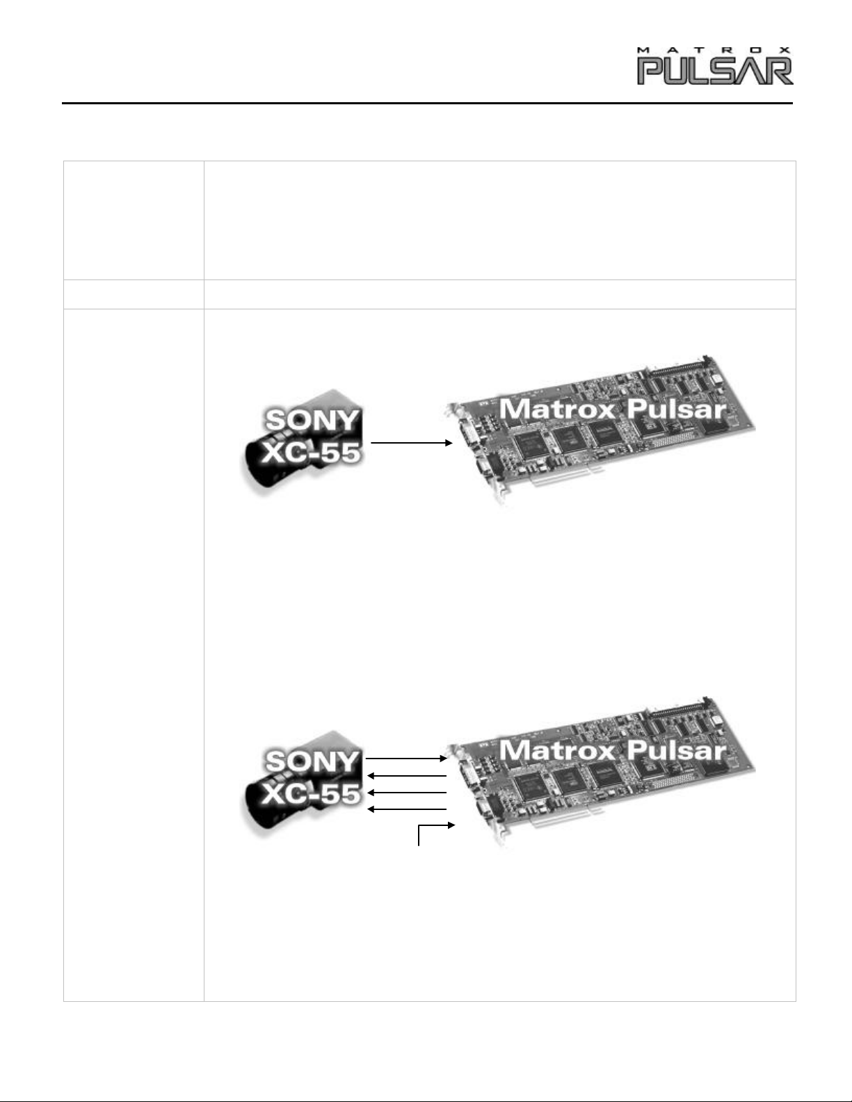
Mode 1: Continuous
E
• 640 × 480 × 8-bits.
• Single channel analog video.
• Interlaced or progressive scan.
• Matrox Pulsar receiving continuous video signals from camera.
• DCF used: XC55N.DCF (Progressive scan)
• DCF used: XC55I.DCF (Interlaced)
Mode 2: Asynchronous reset (E-DONPISHA-II)
PUL-CID-052
TRIGGER
VD
TTL EXTERNAL TRIGGER
• 640 × 480 × 8-bits.
• Single channel analog video.
• Progressive scan.
• Matrox Pulsar receiving TTL external trigger.
• Matrox Pulsar sending EXPOSURE1 (TRIGGER) signal to camera; EXPOSURE1
(TRIGGER) signal sent to reset pixels and initiate exposure.
• DCF used: XC55NA.DCF
Page 2
Application Note:
Interfacing non-standard cameras to Matrox Pulsar
SONY XC-55 July 18, 2000
Camera
Interface
Details
Camera Switch settings (External /Internal)
Mode 1: Continuous (Interlaced) 1l / Factory settings
Mode 2: Continuous (Progressive scan) 1N / Factory settings
Mode 3: Asynchronous reset (E-DONPISHA-II) 1N / S2 = E
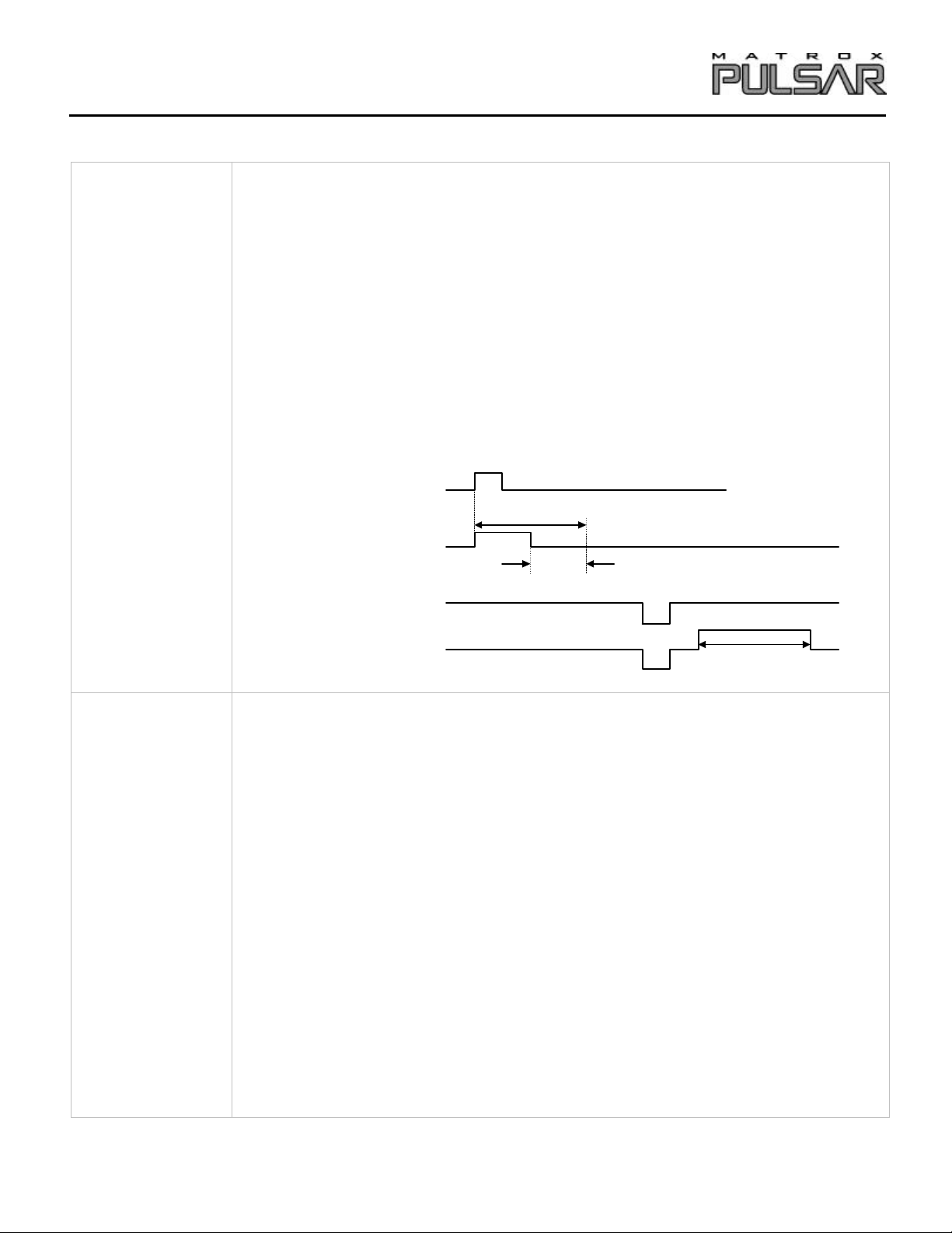
Mode 2: Asynchronous reset (E-DONPISHA-II)
• The frame rate is determined by the period of the TTL external trigger.
• The external trigger is input on the Matrox Pulsar via the analog trigger input.
• Once this external trigger is received, the Matrox Pulsar generates an EXPOSURE1
(TRIGGER) pulse, which in turn initiates camera exposure.
• The exposure time is the EXPOSURE1 (TRIGGER) period plus a fixed internal camera
delay of 8 µsec.
TTL External Trigger
Exposure Time
EXPOSURE1 (TRIGGER)
Delay 8 ms
Exposure2 (VD)
Cabling
Requirements
Video (Video Out)
Mode 1: Continuous
• IMG-7W2-TO-5BNC (red BNC) or IMG-7W2-TO-1BNC cable required for video output
of camera.
Mode 2: Asynchronous reset (E-DONPISHA)
Video Valid
• IMG-7W2-TO-5BNC and PLS-TTL-CABLE cables required for TTL external trigger signal
and for video output of camera.
• TTL external trigger source should be connected to the TTL trigger input of the IMG-7W2-
TO-5BNC cable.
• Connections between the 37-pin connector of the Matrox Pulsar (PLS-TTL-CABLE) and
the 12-pin connector of the camera are as follows:
Matrox Pulsar Sony XC-55
(37-pin connector) (12-pin connector)
Pin name Pin no. Pin name Pin no.
TTL_ EXPOSURE1 09
TTL_ EXPOSURE2
27
→
→
GROUND 23 -- GROUND 08
TTL_ HSYNC 26
→
continued
EXT. TRIGGER INPUT 09
VD 07
HD 06
PUL-CID-052
2
Page 3

Application Note:
Interfacing non-standard cameras to Matrox Pulsar
SONY XC-55 July 18, 2000
Cabling
Requirements
(continued)
Power Supply
Pin name
+ 12 volts -- -- + 12 volts 11
GROUND -- -- GROUND 10
Sony XC-55
(12-pin connector)
The DCF(s) mentioned in this application note can be found on the MIL and MIL-Lite CD, or our FTP site (ftp.matrox.com). The information
furnished by Matrox Electronics System, Ltd. is believed to be accurate and reliable. Please verify all interface connections with camera
documentation or manual. Contact your local sales representative or Matrox Sales office or Imaging Applications at 514-822-6061 for assistance.
Corporate
headquarters:
Canada and U.S.A.
Matrox Electronic Systems
Ltd.
1055 St. Regis Blvd.
Dorval, Quebec H9P 2T4
Canada
Tel: (514) 685-2630
Fax: (514) 822-6273
PUL-CID-052
3
 Loading...