

Matrixx MX-100, MX-150, MX-200 Maintenance Manual

Installation, Operation and
Maintenance Manual
US Water Matrixx Water
Softener
Hardness and Scale Prevention
System.
Matrixx MX-100
Matrixx MX-150
Matrixx MX-200
& HTO Systems
US Water Systems, Inc.
1209 Country Club Road
Indianapolis, IN 46234
1-800-608-8792
info@uswatersystems.com
www.uswatersystems.com

Installation, Operation and Maintenance Manual
Matrixx MX-100, MX-150, MX-200 System
Table of Contents
System Specifications ............................................................................. 3
How Your Water Conditioner Works ....................................................... 4
Main Valve Functions .............................................................................. 5
Tank Installation……………………………………………………………….7
General Installations ............................................................................... 8
Start-up Instructions………………………………………………………....10
Level 1 User Programming.....................................................................11
Level 2 User Programming………………………………………………….13
Level 2 Programming Flow Chart……………………………………….….14
Diagnostic Mode & Vacation Setting.......................................................15
Valve Cycle Settings...............................................................................16
Maintenance……………..…………………………………………………...18
Valve Drive Assembly Exploded View……………………………...……..20
Control Valve Assembly Exploded View………………………..…………21
Troubleshooting………………….…………………………………………..22
Warranty……………………….……………………………………………...23
HTO Installation & Quick Start Sheet……………………………………...24
2

Installation, Operation and Maintenance Manual
Matrixx MX-100, MX-150, MX-200 System
System Specifications
Figure 1. Specifications
US Water Systems classifies each softener according to the actual resin capacity. However, this is not the
regeneration capacity. The regeneration capacity will be lower than the actual resin capacity. This is due to
the resin ’ s regeneration salt curve. For example:
A 53,000 grain unit would require 30 lbs of salt during regeneration if the capacity was set to the actual resin
capacity ( 53,000 grains ) . If the unit is set at 37,000 grains it can be regenerated using only 10 lbs of salt.
The unit is much more efficient when it is set using the proper salt curve capacity and salt dosage levels. So
you can see that to get the final 16,000 grains from a 53,000 grain unit the salt usage will more than double.
Please use the chart below when setting you softener. This will ensure efficiency and longevity of your unit.
Maximum Water Temperature = 110°F (43°C)
Maximum Operating Pressure = 100
PSIG (689 kPa)
Voltage = 110 volts standard
Pipe Size = 3/4”
At the stated service flow rates, the pres-
sure drop through these devices will not
exceed 15 psig.
Changing salt settings from factory setting
may require changing injector sizes to
achieve stated capacities.
The manufacturer reserves the right to make
product improvements which may deviate from
the specifications and descriptions stated herein,
without obligation to change previously manufac-
Model # System Capacity Grains Flow Rate Regeneration Water Mineral
@ 10
lbs/cu ft
085-MX-100 25,000 20,000 13,000 10.0 2.0 38.0 48.0 9 X 48 1.00 15 X 15 X
085-MX-150 37,000 30,000 18,000 12.0 2.4 48.5 60.5 10 X 54 1.50 15 X 15 X
085-MX-200 50,000 40,000 25,000 15.0 3.5 80.5 95.5 12 X 52 2.00 20.3 X 37.4 385 158
@6 lbs/
cu ft
(Factory
Settings)
@ 3 lbs/
cu ft
Service
USGPM
Back-
wash
USGPM
Clean
Water
(Factory
Setting)
tured products or to note the change.
Problem
Water
Tank
Size
Resin
Cu. Ft.
Brine Tank/
Cabinet
Size Inches
34.7
34.7
Salt
Capacity
(Lbs)
230 122
230 155
Weight
For the HTO systems use the following chart.
Ship
(Lbs)
24,000
4.7
37,000 44,000
7.1 9.5
3
Installation, Operation and Maintenance Manual
Matrixx MX-100, MX-150, MX-200 System
How Your Water Conditioner Works
The principle behind water softening is simple chemistry. A water softener contains resin beads which hold electrically
charged ions. When hard water passes through the softener, calcium and magnesium ions are attracted to the charged resin
beads. It's the resulting removal of calcium and magnesium ions that produces soft water.
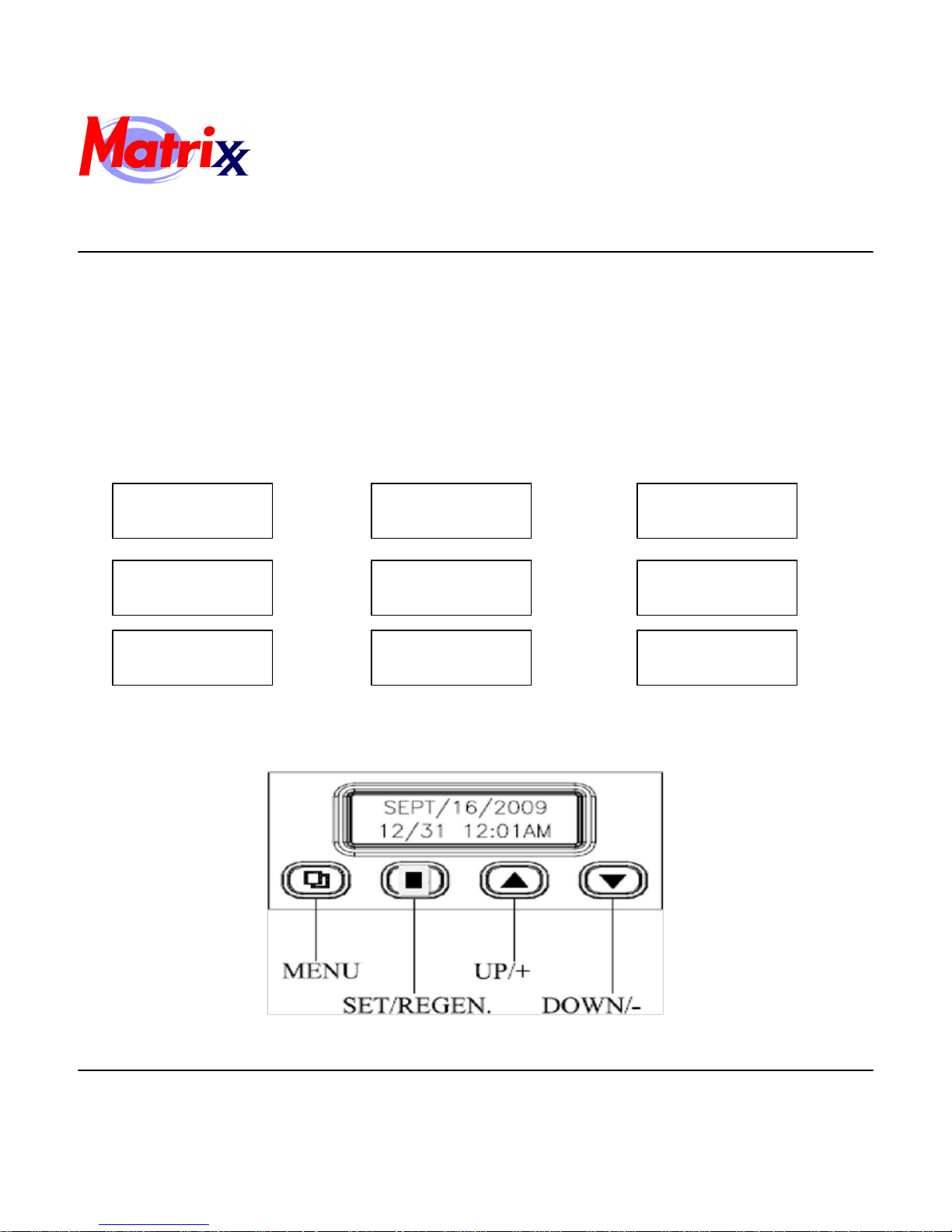
This valve is controlled with simple, user-friendly electronics displayed on a large LCD screen. The main page displays the
current date and time. In addition, the main page also shows key valve information and statistics including: current capacity
setting, volume remaining, date of last regeneration, current flow rate, and peak flow rate.
Figure 2. Main Page Displays
MAY 8, 2012
2:30 PM
REGEN DAYS
7 DAYS
LAST REGEN
MAY 2, 2012
CAPACITY
1,545 GAL
REMAINING DAYS
5 DAYS
CURRENT FLOW
15 GPM
VOLUME REMAING
1,295 GAL
REGENERATION
TIME 2:00 AM
PEAK FLOW
5.8 GPM
NOTE:REGEN DAYS and REMAINING DAYS are only shown in the CALENDAR CLOCK mode or METER OVERRIDE mode.
Figure 3. Key Pad Configuration
4
Installation, Operation and Maintenance Manual
Matrixx MX-100, MX-150, MX-200 System
MENU BUTTON The function of this key is to enter level one programming mode where the valve settings
can be adjusted.
SET / REGEN BUTTON This button has two functions. The first is to initiate a manual regeneration by holding the
button for 3 or more seconds. The second function is while in programming mode, pressing
this key allows the user to change the value of each setting.
UP / DOWN ARROWS These buttons are used to increase or decrease the value of the settings while in the
programming mode.
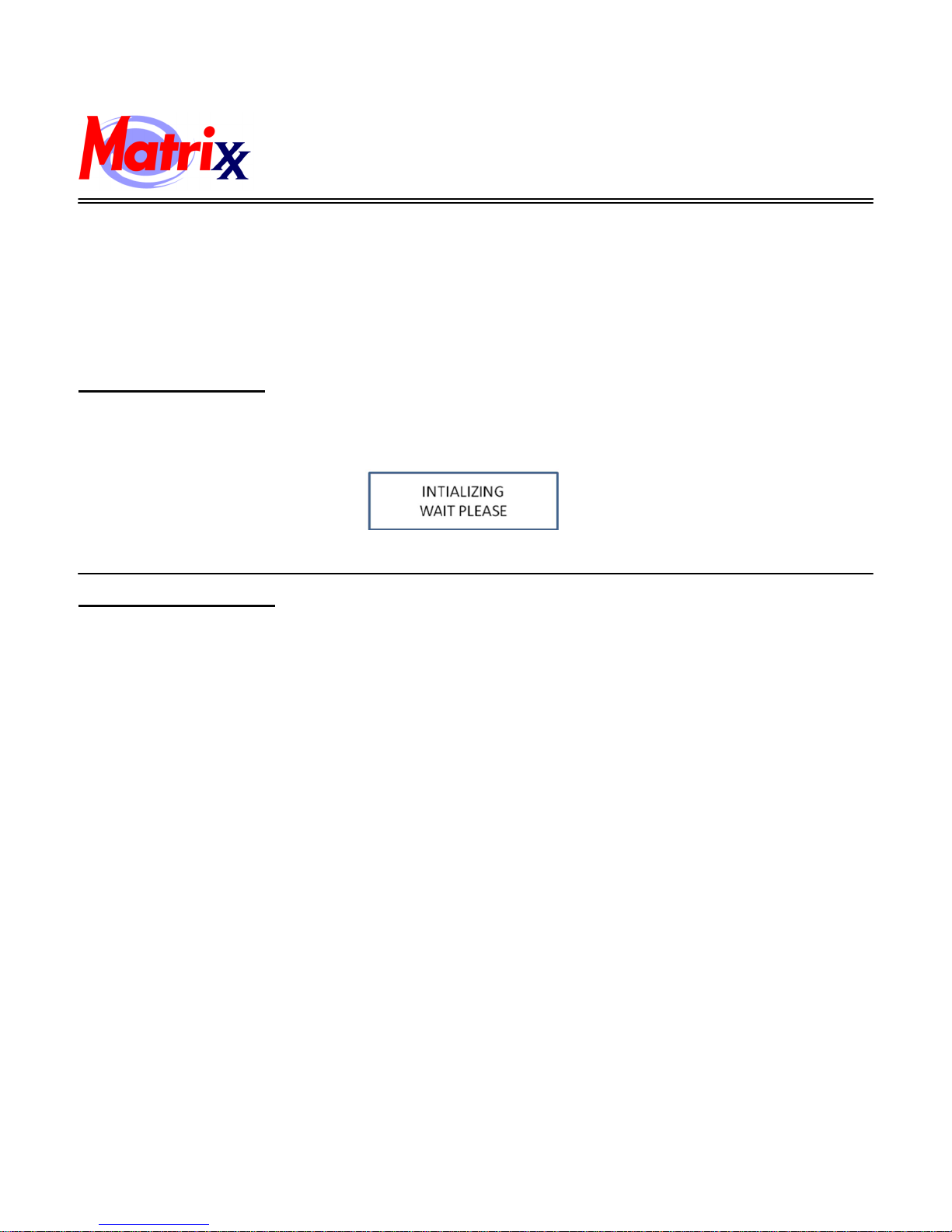
System Initialization
When power is first supplied, the valve may take up to two minutes to initialize the valve. During this time the valve will
show “INTIALIZING WAIT PLEASE”. Do not touch any buttons at this time. When the valve reaches the service position, it will display the current date and time.
Figure 4. System Initialization Display
Main Valve Functions
VALVE OPERATION MODE:
SOFTENER: Standard water softener operation.
FILTER: Automatic back washing filters such as Multi-Media Depth Filter or Carbon Filter.
IRON FILTER: This mode is typically used with Manganese Green Sand Filters.
RE G ENERATION M O D E: 1. METER DELAYED 2. METER I M MEDIATE 3. CALENDAR C LOCK
4. METER OVERRIDE
CAPACITY CALCULATION: 1. AUTOMATIC 2. MANUAL
ADJUSTABLE CYCLES: All of the valve cycles are fully adjustable.
1. BACKWASH 2. BRINE / RINSE
3.RINSE 4. REFILL
NOTE: Refer to Level II User Programming for description of each mode.
5
Installation, Operation and Maintenance Manual
Matrixx MX-100, MX-150, MX-200 System
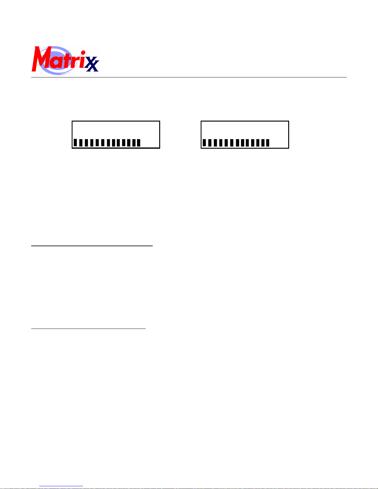
During a regeneration cycle, the valve will display what position it is advancing to. Once in the correct position, the valve
will display the current position along with the time remaining for that cycle. On the bottom row, the time remaining is also
graphically displayed.
BACKWASH
Figure 4. Regeneration Cycle Valve Display
“MENU BUTTON”: The funcon of this key is to enter the level one programming mode where the valve set
tings can be adjusted.
“SET / REGEN BUTTON”: This buon has two funcons. The rst is to initiate a manual regeneration by holding the
button for 3 or more seconds. The second function is while in programming mode,
pressing this key allows the user to change the value of each setting.
“UP / DOWN”: These buons are used to increase or decrease the value of the settings while in the
programming mode.
REMAINING 6 MIN
Manual Regeneration (Delayed or Immediate)
If screen is locked, press “MENU” for 3 seconds to unlock. To iniate an immediate regeneration, press the SET / REGEN
button for 3 seconds, an option for delayed or immediate regeneration will appear. Press the SET / REGEN button again and
delayed will begin flashing, press the down arrow button to have immediate flash, press the SET / REGEN button and then
press the menu button and the valve will immediately start into manual regeneration.
To initiate a delayed regeneration, press the SET / REGEN button for 3 seconds, then press the menu button and a regeneration
will be queued to the next pre-set regeneration time (2:00 a.m.).
Control Operation During A Power Failure
In the event of power failure, the valve will keep track of the time and day for 48 hours. The programmed settings are stored in
a non-volatile memory and will not be lost during a power failure.
If power fails while the unit is in regeneration, the valve will move to the service position from the point it is at once power is
restored. However, since the unit did not complete its regeneration, it will queue another regeneration at the next scheduled
regeneration time.
If the valve misses a scheduled regeneration due to a power failure, it will queue a regeneration at the next regeneration ti me
once power is restored.
6
Installation, Operation and Maintenance Manual
Matrixx MX-100, MX-150, MX-200 System
Matrixx Tank Installation Instructions
WATER PRESSURE: A minimum of 20 pounds of water pressure is required for regeneration valve to operate effectively.
ELECTRICAL FACILITIES: An uninterrupted alternating current (A/C) supply is required. Note: Other voltages are availa-
ble. Please make sure your voltage supply is compatible with your unit before installation.
EXISTING PLUMBING: Condition of existing plumbing should be free from lime and iron buildup. Piping that is built up heavily
with lime and/or iron should be replaced.
LOCATION OF MATRIXX TANK AND DRAIN: The Infusion tank should be located close to a drain to prevent air breaks and
back flow.
CAUTION: Water pressure is not to exceed 80 psi, water temperature is not to exceed 110°F (43°C), and the unit cannot be subjected to
freezing conditions.
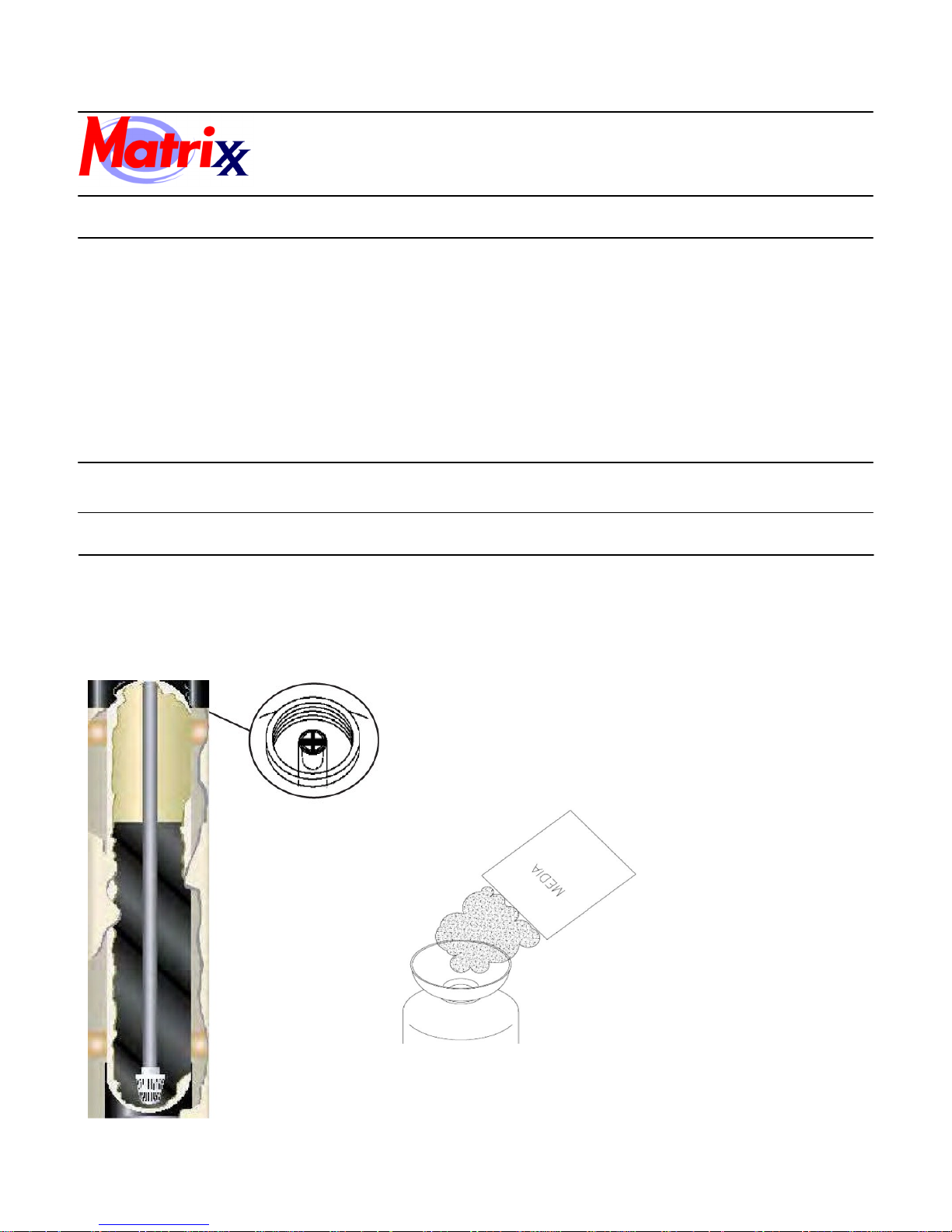
Media Installation
Assembly Instructions
Media Installation (for HTO systems please refer to the Quick Start Guide)
1) Remove the tank from carton.
2) Verify the riser tube is centered in the bottom center of the tank. A flashlight may be necessary.
3) Place a piece of duct tape over the riser tube so no media enters the riser while filling.
4) Make sure the riser is centered to facilitate the valve installation after installation of the media.
5) Use the Blue Funnel provided, to pour the media into the
tank. Pour it evenly around the hole to ensure it is well distributed in the tank and pour slow enough, to keep from
plugging the hole.
6) When media is installed move tank side to side to settle the
media.
7
Installation, Operation and Maintenance Manual
Matrixx MX-100, MX-150, MX-200 System
Assembly Instructions
Valve Installation
1) Remove the tape from the riser and discard.
2) Lubricate the two o-rings with a light coat of Silicone.
3) Install the Upper Basket to the valve, twisting it to lock it in place (if not already installed).
4) Slip the Upper Basket over the Riser sliding it down into place and screw the valve on and tighten.
5) Follow the installation procedures in this manual and program accordingly.
General Installation
Water Pressure Minimum 25 PSI
Electrical Supply Uninterrupted AC
Existing Plumbing Free of any deposits or build-ups inside pipes.
Unit Location
Bypass Valves Always provide for bypass valve if unit is not equipped with one.
Plumbing
Locate close to drain and connect according to plumbing codes
Softener and or other water treatment equipment should be installed to local plumbing codes
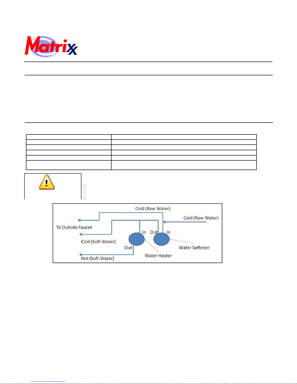
CAUTION
Do not exceed 120 psi water pressure.
Do not exceed 110°F water temperature.
Do not subject unit to freezing conditions.
Figure 5. Piping Diagram
1. Locate the softener tank and brine tank close to a drain where the system will be installed. The surface should be clean a nd
level.
8
 Loading...