

Page 1
mvHYPERION-Series
Technical Manual
Page 2

CONTENTS i
Contents
1 About this manual 2
1.1 Composition of the manual . . . . . . . . . . . . . . . . . . . . . . . . . . . . . . . . . . . . . . 2
1.2 How to get started? . . . . . . . . . . . . . . . . . . . . . . . . . . . . . . . . . . . . . . . . . . 2
1.2.1 Introduction . . . . . . . . . . . . . . . . . . . . . . . . . . . . . . . . . . . . . . . . . . 2
1.2.2 Basics . . . . . . . . . . . . . . . . . . . . . . . . . . . . . . . . . . . . . . . . . . . . . 3
1.2.3 Image acquisition concept . . . . . . . . . . . . . . . . . . . . . . . . . . . . . . . . . . 5
1.2.4 Installation . . . . . . . . . . . . . . . . . . . . . . . . . . . . . . . . . . . . . . . . . . 5
1.2.5 Programming . . . . . . . . . . . . . . . . . . . . . . . . . . . . . . . . . . . . . . . . . 6
2 Imprint 7
3 Revisions 8
4 Graphic Symbols 10
4.1 Notes, Warnings, Attentions . . . . . . . . . . . . . . . . . . . . . . . . . . . . . . . . . . . . . . 10
4.2 Webcasts . . . . . . . . . . . . . . . . . . . . . . . . . . . . . . . . . . . . . . . . . . . . . . . 10
5 Important information 11
5.1 European Union Declaration of Conformity statement . . . . . . . . . . . . . . . . . . . . . . . . 11
6 Introduction 14
6.1 What's inside and accessories . . . . . . . . . . . . . . . . . . . . . . . . . . . . . . . . . . . . 14
7 Quickstart 15
7.1 Hardware installation . . . . . . . . . . . . . . . . . . . . . . . . . . . . . . . . . . . . . . . . . 15
7.2 Windows . . . . . . . . . . . . . . . . . . . . . . . . . . . . . . . . . . . . . . . . . . . . . . . . 15
7.2.1 System Requirements . . . . . . . . . . . . . . . . . . . . . . . . . . . . . . . . . . . . 15
7.2.2 Software installation . . . . . . . . . . . . . . . . . . . . . . . . . . . . . . . . . . . . . 16
7.3 Linux . . . . . . . . . . . . . . . . . . . . . . . . . . . . . . . . . . . . . . . . . . . . . . . . . . 20
7.3.1 System Requirements . . . . . . . . . . . . . . . . . . . . . . . . . . . . . . . . . . . . 20
7.3.2 Installing the mvIMPACT Acquire driver . . . . . . . . . . . . . . . . . . . . . . . . . . . 21
7.4 Connecting a camera . . . . . . . . . . . . . . . . . . . . . . . . . . . . . . . . . . . . . . . . . 25
7.5 Settings behavior during startup . . . . . . . . . . . . . . . . . . . . . . . . . . . . . . . . . . . 25
MATRIX VISION GmbH
Page 3

ii CONTENTS
8 Technical data 28
8.1 mvHYPERION-CLx . . . . . . . . . . . . . . . . . . . . . . . . . . . . . . . . . . . . . . . . . . 28
8.1.1 Block diagrams . . . . . . . . . . . . . . . . . . . . . . . . . . . . . . . . . . . . . . . . 28
8.1.2 Connectors . . . . . . . . . . . . . . . . . . . . . . . . . . . . . . . . . . . . . . . . . . 28
8.1.3 Components . . . . . . . . . . . . . . . . . . . . . . . . . . . . . . . . . . . . . . . . . 37
8.1.4 Device Feature And Property Lists . . . . . . . . . . . . . . . . . . . . . . . . . . . . . . 38
8.2 mvHYPERION-32R16 . . . . . . . . . . . . . . . . . . . . . . . . . . . . . . . . . . . . . . . . . 38
8.2.1 Block diagram . . . . . . . . . . . . . . . . . . . . . . . . . . . . . . . . . . . . . . . . . 38
8.2.2 Connectors . . . . . . . . . . . . . . . . . . . . . . . . . . . . . . . . . . . . . . . . . . 39
8.2.3 Components . . . . . . . . . . . . . . . . . . . . . . . . . . . . . . . . . . . . . . . . . 40
8.3 mvHYPERION-HD-SDI . . . . . . . . . . . . . . . . . . . . . . . . . . . . . . . . . . . . . . . . 41
8.3.1 Block diagram . . . . . . . . . . . . . . . . . . . . . . . . . . . . . . . . . . . . . . . . . 41
8.3.2 Connectors . . . . . . . . . . . . . . . . . . . . . . . . . . . . . . . . . . . . . . . . . . 42
8.3.3 Components . . . . . . . . . . . . . . . . . . . . . . . . . . . . . . . . . . . . . . . . . 44
9 Application Usage 48
9.1 wxPropView . . . . . . . . . . . . . . . . . . . . . . . . . . . . . . . . . . . . . . . . . . . . . . 48
9.1.1 How to work with wxPropView . . . . . . . . . . . . . . . . . . . . . . . . . . . . . . . . 48
9.1.2 How to configure a device . . . . . . . . . . . . . . . . . . . . . . . . . . . . . . . . . . 69
9.1.3 Command-line options . . . . . . . . . . . . . . . . . . . . . . . . . . . . . . . . . . . . 94
9.2 mvDeviceConfigure . . . . . . . . . . . . . . . . . . . . . . . . . . . . . . . . . . . . . . . . . . 95
9.2.1 How to set the device ID . . . . . . . . . . . . . . . . . . . . . . . . . . . . . . . . . . . 95
9.2.2 How to update the firmware . . . . . . . . . . . . . . . . . . . . . . . . . . . . . . . . . . 97
9.2.3 How to recover a broken firmware update . . . . . . . . . . . . . . . . . . . . . . . . . . 100
9.2.4 How to allocate image memory . . . . . . . . . . . . . . . . . . . . . . . . . . . . . . . . 101
9.2.5 How to disable CPU sleep states a.k.a. C states (< Windows 8) . . . . . . . . . . . . . . 102
9.2.6 Command-line options . . . . . . . . . . . . . . . . . . . . . . . . . . . . . . . . . . . . 103
10 HRTC - Hardware Real-Time Controller 106
10.1 Introduction . . . . . . . . . . . . . . . . . . . . . . . . . . . . . . . . . . . . . . . . . . . . . . 106
10.1.1 Operating codes . . . . . . . . . . . . . . . . . . . . . . . . . . . . . . . . . . . . . . . 106
10.1.2 Program controls . . . . . . . . . . . . . . . . . . . . . . . . . . . . . . . . . . . . . . . 106
10.2 How to use the HRTC . . . . . . . . . . . . . . . . . . . . . . . . . . . . . . . . . . . . . . . . . 107
MATRIX VISION GmbH
Page 4

CONTENTS iii
11 C developers 108
12 C++ developers 109
13 .NET developers 110
14 Python developers 111
14.1 Introduction . . . . . . . . . . . . . . . . . . . . . . . . . . . . . . . . . . . . . . . . . . . . . . 111
14.2 Building . . . . . . . . . . . . . . . . . . . . . . . . . . . . . . . . . . . . . . . . . . . . . . . . 111
14.2.1 Windows . . . . . . . . . . . . . . . . . . . . . . . . . . . . . . . . . . . . . . . . . . . 111
14.2.2 Linux . . . . . . . . . . . . . . . . . . . . . . . . . . . . . . . . . . . . . . . . . . . . . 112
14.3 Using . . . . . . . . . . . . . . . . . . . . . . . . . . . . . . . . . . . . . . . . . . . . . . . . . 112
15 DirectShow Interface 115
15.1 Supported Interfaces . . . . . . . . . . . . . . . . . . . . . . . . . . . . . . . . . . . . . . . . . 115
15.1.1 IAMCameraControl . . . . . . . . . . . . . . . . . . . . . . . . . . . . . . . . . . . . . . 115
15.1.2 IAMDroppedFrames . . . . . . . . . . . . . . . . . . . . . . . . . . . . . . . . . . . . . 115
15.1.3 IAMStreamConfig . . . . . . . . . . . . . . . . . . . . . . . . . . . . . . . . . . . . . . . 115
15.1.4 IAMVideoProcAmp . . . . . . . . . . . . . . . . . . . . . . . . . . . . . . . . . . . . . . 115
15.1.5 IKsPropertySet . . . . . . . . . . . . . . . . . . . . . . . . . . . . . . . . . . . . . . . . 115
15.1.6 ISpecifyPropertyPages . . . . . . . . . . . . . . . . . . . . . . . . . . . . . . . . . . . . 115
15.2 Logging . . . . . . . . . . . . . . . . . . . . . . . . . . . . . . . . . . . . . . . . . . . . . . . . 115
15.3 Registering and renaming devices for DirectShow usage . . . . . . . . . . . . . . . . . . . . . . . 116
15.3.1 Registering devices . . . . . . . . . . . . . . . . . . . . . . . . . . . . . . . . . . . . . . 116
15.3.2 Renaming devices . . . . . . . . . . . . . . . . . . . . . . . . . . . . . . . . . . . . . . 118
15.3.3 Make silent registration . . . . . . . . . . . . . . . . . . . . . . . . . . . . . . . . . . . . 119
16 Glossary 120
MATRIX VISION GmbH
Page 5

CONTENTS 1
17 Use cases 122
17.1 scanCameras Working with line scan cameras . . . . . . . . . . . . . . . . . . . . . . . . . . . . 122
17.2 Pass-through of digital input signals . . . . . . . . . . . . . . . . . . . . . . . . . . . . . . . . . . 122
17.3 Working with pulse start events . . . . . . . . . . . . . . . . . . . . . . . . . . . . . . . . . . . . 123
17.4 Working with an rotary encoder . . . . . . . . . . . . . . . . . . . . . . . . . . . . . . . . . . . . 124
17.4.1 DigitalSignalA . . . . . . . . . . . . . . . . . . . . . . . . . . . . . . . . . . . . . . . . . 125
17.4.2 DigitalSignalB . . . . . . . . . . . . . . . . . . . . . . . . . . . . . . . . . . . . . . . . . 125
17.4.3 PulseMultiplication . . . . . . . . . . . . . . . . . . . . . . . . . . . . . . . . . . . . . . 126
17.4.4 Direction . . . . . . . . . . . . . . . . . . . . . . . . . . . . . . . . . . . . . . . . . . . 126
17.4.5 Mode . . . . . . . . . . . . . . . . . . . . . . . . . . . . . . . . . . . . . . . . . . . . . 126
17.4.6 int Reset() . . . . . . . . . . . . . . . . . . . . . . . . . . . . . . . . . . . . . . . . . . . 127
17.5 Working with a Basler Sprint line scan color camera . . . . . . . . . . . . . . . . . . . . . . . . . 127
17.5.1 Introduction . . . . . . . . . . . . . . . . . . . . . . . . . . . . . . . . . . . . . . . . . . 127
17.5.2 RawLineAcquisition Mode . . . . . . . . . . . . . . . . . . . . . . . . . . . . . . . . . . 129
17.5.3 EnhancedRawLineAcquisition Mode . . . . . . . . . . . . . . . . . . . . . . . . . . . . . 131
17.6 Working with trigger events . . . . . . . . . . . . . . . . . . . . . . . . . . . . . . . . . . . . . . 135
17.6.1 FrameStart . . . . . . . . . . . . . . . . . . . . . . . . . . . . . . . . . . . . . . . . . . 136
17.6.2 FrameStart + FrameStop . . . . . . . . . . . . . . . . . . . . . . . . . . . . . . . . . . . 137
17.6.3 AcquisitionStart . . . . . . . . . . . . . . . . . . . . . . . . . . . . . . . . . . . . . . . . 139
17.7 Synchronous acquisition with different camera settings . . . . . . . . . . . . . . . . . . . . . . . . 140
MATRIX VISION GmbH
Page 6

2 CONTENTS
1 About this manual
1.1 Composition of the manual
The mvIMPACT Acquire manual for the MATRIX VISION frame grabbers is based on a modular concept. That
means like in many object-oriented programming languages you have for each functionality your own "class". Instead of classes, you have books. For example, if you want to know how images are acquired with the frame
grabbers, have a look in the respective programming language chapter.
Here is a short summary about all books of the frame grabber manual:
• The manual starts with technical data of the frame grabber as well as a quick start chapter.
Afterwards, you will find the different books:
• Application Usage (p. 48)
– The frame grabbers can also be managed via user interface. The program is called wxPropView (p. 48).
• DirectShow developers (p. 115)
– This is the documentation of the MATRIX VISION DirectShow_acquire interface.
• Use cases (p. 122)
– This book offers solutions and explanations for standard use cases.
Note
For C, C++, .NET developers, there are separate mvIMPACT Acquire manuals
• "mvIMPACT_Acquire_API_CPP_manual.chm",
• "mvIMPACT_Acquire_API_C_manual.chm", and
• "mvIMPACT_Acquire_API_NET_manual.chm"
available as downloads from our website http://www.matrix-vision.com. The manuals contain
chapter about
• how to link and build applications using mvIMPACT Acquire,
• how the log output for "mvIMPACT Acquire" devices is configured and how it works in general,
• how to create your own installer packages for Windows and Linux, and
• the general mvIMPACT Acquire API documentation.
1.2 How to get started?
1.2.1 Introduction
This chapter gives you a short overview, how to get started with a MATRIX VISION frame grabber and where to find
the necessary information in the manual. It will also explain or link to the concepts behind the driver and the image
acquisition. Furthermore it shows you how to get start programming own applications.
MATRIX VISION GmbH
Page 7

1.2 How to get started? 3
1.2.2 Basics
1.2.2.1 Driver concept
The driver supplied with the MATRIX VISION product represents the port between the programmer and the
hardware. The driver concept of MATRIX VISION provides a standardized programming interface to all image
processing products (excluding mvBlueLYNX) made by MATRIX VISION GmbH.
The advantage of this concept for the programmer is that a developed application runs without the need for any
major modifications to the various image processing products made by MATRIX VISION GmbH. You can also
incorporate new driver versions, which are available for download free of charge on our website.
The following diagram shows a schematic structure of the driver concept:
Figure 1: Driver concept
• 1 Part of any mvIMPACT Acquire driver installation package (Windows).
• 2 Separately available for 32 bit and 64 bit. Requires at least one installed driver package.
• 3 See 2, but requires an installed version of the mvBlueFOX driver.
• 4 Part of the NeuroCheck installer but requires at least one installed frame grabber driver.
• 5 Part of the mvIMPACT SDK installation. However, new designs should use the .NET libs that are now part
of mvIMPACT Acquire ("mv.impact.acquire.dll"). The namespace "mv.impact.acquire" of
"mv.impact.acquire.dll" provides a more natural and more efficient access to the same features
as contained in the namespace "mvIMPACT_NET.acquire" of "mvIMPACT_NET.dll", which is why
the latter one should only be used for backward compatibility but NOT when developing a new application.
• 6 Part of Micro-Manager.
MATRIX VISION GmbH
Page 8

4 CONTENTS
1.2.2.2 NeuroCheck support
A couple of devices are supported by NeuroCheck. However between NeuroCheck 5.x and NeuroCheck 6.x there
has been a breaking change in the internal interfaces. Therefore also the list of supported devices differs from one
version to another and some additional libraries might be required.
For NeuroCheck 5.x the following devices are supported:
Device Additional software needed
mvTITAN-G1 mvSDK driver for mvTITAN/mvGAMMA devices
mvTITAN-CL mvSDK driver for mvTITAN/mvGAMMA devices
mvGAMMA-CL mvSDK driver for mvTITAN/mvGAMMA devices
mvBlueFOX mvIMPACT Acquire driver for mvBlueFOX devices, "NCUSBmvBF.dll"
For NeuroCheck 6.0 the following devices are supported:
Device Additional software needed
mvTITAN-G1 mvIMPACT Acquire driver for mvTITAN/mvGAMMA de-
vices
mvTITAN-CL mvIMPACT Acquire driver for mvTITAN/mvGAMMA de-
vices
mvGAMMA-CL mvIMPACT Acquire driver for mvTITAN/mvGAMMA de-
vices
mvHYPERION-CLb mvIMPACT Acquire driver for mvHYPERION devices
Every other mvIMPACT Acquire compliant device mvIMPACT Acquire driver for the corresponding device
family, "mv.impact.acquire.NeuroCheck6.←-
dll" (comes with the driver package, but the driver
package must be installed AFTER installing NeuroCheck 6
For NeuroCheck 6.1 the following devices are supported:
Device Additional software needed
mvTITAN-G1 mvIMPACT Acquire driver for mvTITAN/mvGAMMA de-
vices
mvTITAN-CL mvIMPACT Acquire driver for mvTITAN/mvGAMMA de-
vices
mvGAMMA-CL mvIMPACT Acquire driver for mvTITAN/mvGAMMA de-
vices
mvHYPERION-CLb mvIMPACT Acquire driver for mvHYPERION devices
Every other mvIMPACT Acquire compliant device mvIMPACT Acquire driver for the corresponding device
family, "mv.impact.acquire.NeuroCheck6_←-
1.dll" (comes with the driver package, but the driver
package must be installed AFTER installing NeuroCheck
6.1
1.2.2.3 VisionPro support
Every mvIMPACT Acquire driver package under Windows comes with an adapter to VisionPro from Cognex. The
installation order does not matter. After the driver package and VisionPro has been installed, the next time VisionPro
is started it will allow selecting the mvIMPACT Acquire device. No additional steps are needed.
MATRIX VISION devices that also comply with the GigE Vision or USB3 Vision standard don't need any software
at all, but can also use VisionPro's built-in GigE Vision or USB3 Vision support.
MATRIX VISION GmbH
Page 9

1.2 How to get started? 5
1.2.2.4 HALCON support
HALCON comes with built-in support for mvIMPACT Acquire compliant devices, so once a device driver has been
installed for the mvIMPACT Acquire device, it can also be operated from a HALCON environment using the corresponding acquisition interface. No additional steps are needed.
MATRIX VISION devices that also comply with the GigE Vision or USB3 Vision standard don't need any software
at all, but can also use HALCON's built-in GigE Vision or USB3 Vision support.
As some mvIMPACT Acquire device driver packages also come with a GenTL compliant interface, these can also
be operated through HALCON's built-in GenTL acquisition interface.
1.2.2.5 LabVIEW support
Every mvIMPACT Acquire compliant device can be operated under LabVIEW through an additional set of VIs which
is shipped by MATRIX VISION as a separate installation ("mvLabVIEW Acquire").
MATRIX VISION devices that also comply with the GigE Vision or USB3 Vision standard don't need any additional
software at all, but can also be operated through LabVIEW's GigE Vision or USB3 Vision driver packages.
1.2.2.6 DirectShow support
Every mvIMPACT Acquire compliant device driver package comes with an interface to DirectShow. In order to be
usable from a DirectShow compliant application, devices must first be registered for DirectShow support. How to
this is explained here (p.116).
1.2.2.7 Micro-Manager support
Every mvIMPACT Acquire compliant device can be operated under https://micro-manager.org when
using mvIMPACT Acquire 2.18.0 or later and at least Micro-Manager 1.4.23 build AFTER 15.12.2016. The
adapter needed is part of the Micro-Manager release. Additional information can be found here: https←-
://micro-manager.org/wiki/MatrixVision.
1.2.3 Image acquisition concept
The image acquisition is based on queues to avoid the loss of single images. With this concept you can acquire images via single acquisition or triggered acquisition. For detailed description of the acquisition concept, please have
a look at "How the capture process works" in the mvIMPACT_Acquire_API manual matching the programming
language you are working with.
1.2.4 Installation
To install the frame grabber properly you have to follow these steps:
(Please follow the links for detailed descriptions.)
• Windows:
– Please check the system requirements (p.15).
– Please install the software and driver (p. 16).
– Please install the hardware (p.15).
• Linux:
– Please check the system requirements (p.20).
– Please install the software and driver (p. 21).
– Please install the hardware (p.15).
MATRIX VISION GmbH
Page 10

6 CONTENTS
1.2.5 Programming
To control the camera and handle the images, you will have a good introduction by reading the main pages of the
"mvIMPACT Acquire" interface references. Additionally, please have a look at the example programs. Several
basic examples are available. The separate mvIMPACT Acquire manuals
• "mvIMPACT_Acquire_API_CPP_manual.chm",
• "mvIMPACT_Acquire_API_C_manual.chm", and
• "mvIMPACT_Acquire_API_NET_manual.chm"
are available as downloads from our website http://www.matrix-vision.com.
MATRIX VISION GmbH
Page 11

2 Imprint 7
2 Imprint
MATRIX VISION GmbH
Talstrasse 16
DE - 71570 Oppenweiler
Telephone: +49-7191-9432-0
Fax: +49-7191-9432-288
Website: http://www.matrix-vision.de
E-Mail:
info@matrix-vision.de
support@matrix-vision.de
jobs@matrix-vision.de
Author
U. Lansche
Date
2016
This document assumes a general knowledge of PCs and programming.
Since the documentation is published electronically, an updated version may be available online. For this reason we
recommend checking for updates on the MATRIX VISION website.
MATRIX VISION cannot guarantee that the data is free of errors or is accurate and complete and, therefore, assumes no liability for loss or damage of any kind incurred directly or indirectly through the use of the information of
this document.
MATRIX VISION reserves the right to change technical data and design and specifications of the described products
at any time without notice.
Copyright
MATRIX VISION GmbH. All rights reserved. The text, images and graphical content are protected by copyright
and other laws which protect intellectual property. It is not permitted to copy or modify them for trade use or
transfer. They may not be used on websites.
• Windows® XP, Windows® Vista, Windows® 7 are trademarks of Microsoft, Corp.
• Linux® is a trademark of Linus Torvalds.
All other product and company names in this document may be the trademarks and tradenames of their
respective owners and are hereby acknowledged.
The manual has been generated with Doxygen (Website: http://www.doxygen.org).
Parts of the log file creation and the log file display make use of Sarissa (Website: http://dev.←-
abiss.gr/sarissa) which is distributed under the GNU GPL version 2 or higher, GNU LGPL version
2.1 or higher and Apache Software License 2.0 or higher. The Apache Software License 2.0 is part of this
driver package.
MATRIX VISION GmbH
Page 12

8 CONTENTS
3 Revisions
Date Description
09. November 2018 Added "Hard Disk Recording" in wxPropView (p.48).
21. December 2016 Added Setting up multiple display support and/or work with several capture
settings in parallel (p. 59).
15. December 2016 Added Micro-Manger in Driver concept (p. 3).
11. March 2015 Added chapter Accessing log files (p. 68).
21. October 2014 Added description about the record mode in How to see the first image (p.50).
28. July 2014 Updated supported image formats of mvHYPERION-HD-SDI-2 in Components
(p. 44).
06. December 2013 Added information about Changing the view of the property grid to assist writing
code that shall locate driver features (p. 67).
15. October 2013 Added Webcasts (p. 10) links.
Added chapter Bit-shifting an image (p. 66).
20. September 2013 Updated ambient temperature of mvHYPERION-CLb: Components (p. 37).
24. January 2013 Added information about image error counts and disabling CPU sleep states: How to
disable CPU sleep states a.k.a. C states (< Windows 8) (p. 102).
14. December 2012 New version of technical documentation.
20. September 2012 Added chapter "Porting existing code written with versions earlier than 3.0.0"
17. July 2012 Firmware Update (p. 100): Corrected "Switch 3" to "Switch 1".
20. April 2012 Added chapter HRTC - Hardware Real-Time Controller (p. 106)
Added use case Working with a Basler Sprint line scan color camera (p. 127)
Added use case Synchronous acquisition with different camera settings (p.140)
16. February 2012 Renewed chapter wxPropView (p.48).
09. November 2011 Added Settings behavior during startup (p. 25) in chapter Quickstart (p. 15).
26. July 2011 Removed chapter EventHandling. See "Porting existing code written with ver-
sions earlier then 2.0.0".
11. July 2011 Added chapter "Callback demo".
06. Jun. 2011 Added chapter "Porting existing code written with versions earlier than 2.0.0".
28. March 2011 Added LED description for mvHYPERION-CLx frame grabbers (p.28).
18. January 2011 Added chapter Setting up multiple display support and/or work with several cap-
ture settings in parallel (p. 59).
07. December 2010 Added chapter How to allocate image memory (p. 101).
19. October 2010 Added chapter "Chunk data format".
01. Oct. 2010 Updated Working with trigger events (p. 135) and Camera acquisition techniques
(p. 89).
Added chapter Working with an rotary encoder (p. 124).
01. Oct. 2010 Updated Components (p. 44) table of (mvHYPERION-HD-SDI-2) and added supported signal formats.
17. Sep. 2010 Corrected image of connector J6 Connectors (p. 28) (mvHYPERION-Clx) and Con-
nectors (p.42) (mvHYPERION-HD-SDI).
02. Aug. 2010 Added chapter Import and Export images (p. 58).
19. Apr. 2010 Added example ContinuousCaptureDirectX.
15. Mar. 2010 Updated chapter mvHYPERION-HD-SDI (p. 41).
17. Feb. 2010 Added chapter Camera acquisition techniques (p. 89).
28. Jan. 2010 Added chapter Copy grid data to the clipboard (p. 58).
13. Jan. 2010 Added chapter "Porting existing code written with versions earlier then 1.12.0".
16. Dec. 2009 Added frame grabber mvHYPERION-32R16 (p. 38).
15. Dec. 2009 Added frame grabber mvHYPERION-HD-SDI (p. 41).
10. Nov. 2009 Added Windows 7 as supported operating system.
MATRIX VISION GmbH
Page 13

3 Revisions 9
05. Nov. 2009 Added example CaptureToUserMemory_C.
04. Nov. 2009 Added chapter Connecting a camera (p. 25).
19. Oct. 2009 Updated wxPropView (p. 48) description about handling settings.
02. Jun. 2009 Please note the remark about connecting PoCL cameras to the mvHYPERION←-
: Hardware installation (p.15).
05. May 2009 Updated wxPropView (p. 48)
Added book Use cases (p. 122), which offers solutions and explanations for standard
use cases.
09. Apr. 2009 Added chapter "Porting existing code written with versions earlier then 1.11.0".
30. Mar. 2009 Added information for - DirectShow developers (p.115).
Added new examples
• DigitalIOs,
• ContinuousCaptureMultipleInputs and
• ContinuousCaptureMultipleVideoSignals.
30. Jan. 2009 Changed Switch numbering of mvHYPERION-CLx (p. 28).
13. Jan. 2009 Added environmental information of mvHYPERION-CLx (p.28).
14. Nov. 2008 Added wxPropView example wxPropView.
18. Aug. 2008 Added new example CaptureToUserMemory.
11. July 2008 Corrected Figure of J6 connector Technical data (p. 28).
18. Jun. 2008 Added chapter Triggering with mvHYPERION (p. 87).
29. Apr. 2008 Added chapter How to recover a broken firmware update (p. 100).
12. Dec. 2007 Added chapter "Pinning J6 (internal digital I/Os)" in Connectors (p.28).
06. Dec. 2007 Updated chapter What's inside and accessories (p. 14).
07. Nov. 2007 Added chapter "Porting existing code written with versions earlier then 1.10.0".
12. Oct. 2007 Updated information about "Opto-isolated digital output" in chapter Connectors
(p. 28).
25. Sep. 2007 Added chapter mvDeviceConfigure (p. 95) and description about "Switches" in
Connectors (p.28).
1. August 2007 Rewritten "How to use this manual". This book now includes a getting started chapter
(see: Composition of the manual (p. 2)).
19. Jun. 2007 Changed installation sequence Quickstart (p. 15).
12. Mar. 2007 Added Linux installation chapter Linux (p. 20).
Feb. 2007 Initial version
MATRIX VISION GmbH
Page 14

10 CONTENTS
4 Graphic Symbols
4.1 Notes, Warnings, Attentions
Note
A note indicates important information that helps you optimize usage of the products.
Warning
A warning indicates how to avoid either potential damage to hardware or loss of data.
Attention
An attention indicates a potential for property damage, personal injury, or death.
All due care and attention has been taken in preparing this manual. In view of our policy of continuous product
improvement, however, we can accept no liability for completeness and correctness of the information contained in
this manual. We make every effort to provide you with a flawless product.
In the context of the applicable statutory regulations, we shall accept no liability for direct damage, indirect damage
or third-party damage resulting from the acquisition or operation of a MATRIX VISION product. Our liability for intent
and gross negligence is unaffected. In any case, the extend of our liability shall be limited to the purchase price.
4.2 Webcasts
This icon indicates a webcast about an issue which is available on our website.
MATRIX VISION GmbH
Page 15
5.1 European Union Declaration of Conformity statement 11
5 Important information
We cannot and do not take any responsibility for the damage caused to you or to any other equipment
connected to the mvHYPERION frame grabber. Similarly, warranty will be void, if a damage is caused
by not following the manual.
Handle the mvHYPERION frame grabber with care. Do not misuse the mvHYPERION frame grabber.
Avoid shaking, striking, etc. The mvHYPERION frame grabber could be damaged by faulty handling
or shortage.
• Handle with care and avoid damage of electrical components by electrostatic discharge (ESD):
– Discharge body static (contact a grounded surface and maintain contact).
– Avoid all plastic, vinyl, and styrofoam (except antistatic versions) around printed circuit
boards.
– Do not touch components on the printed circuit board with your hands or with conductive
devices.
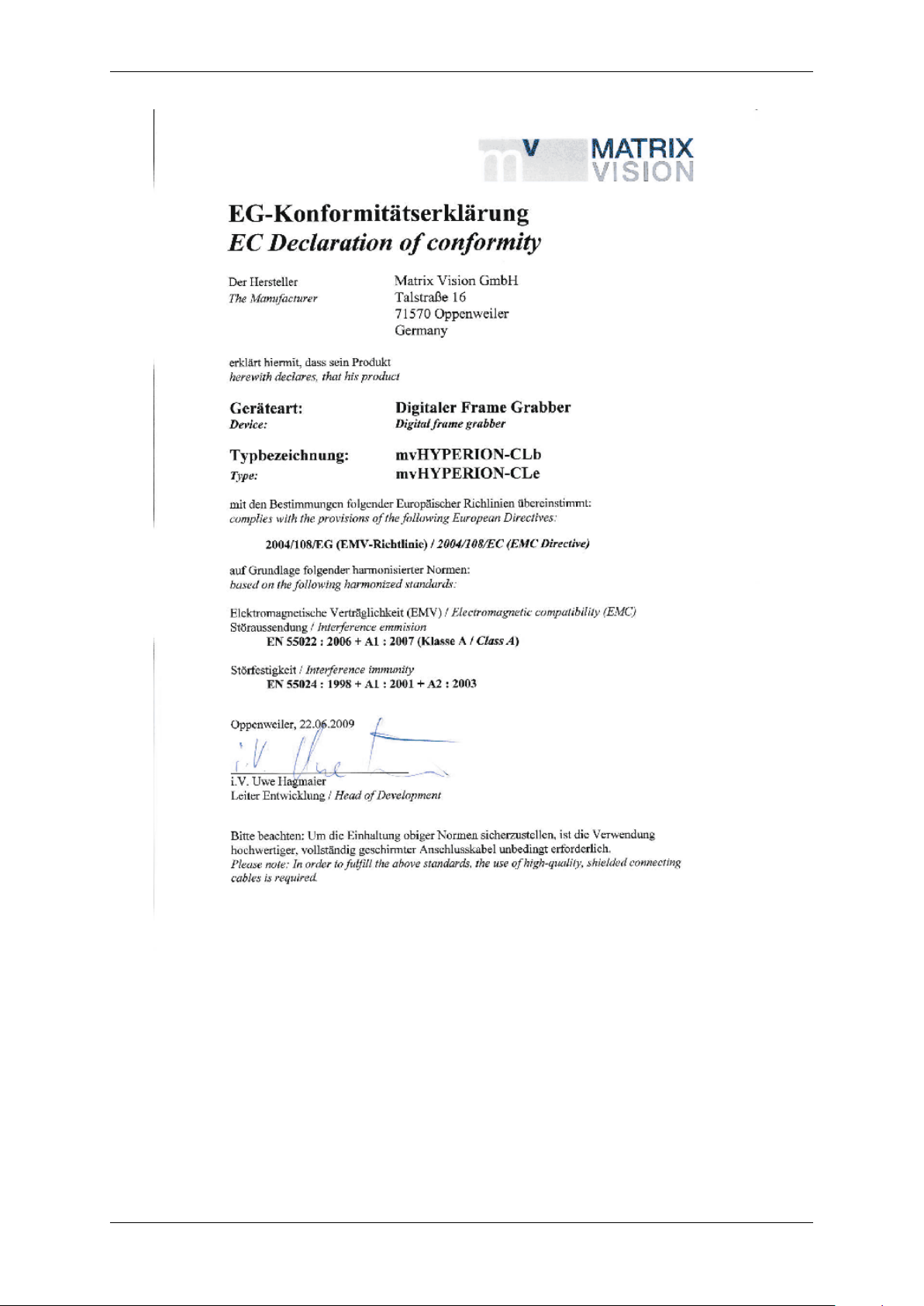
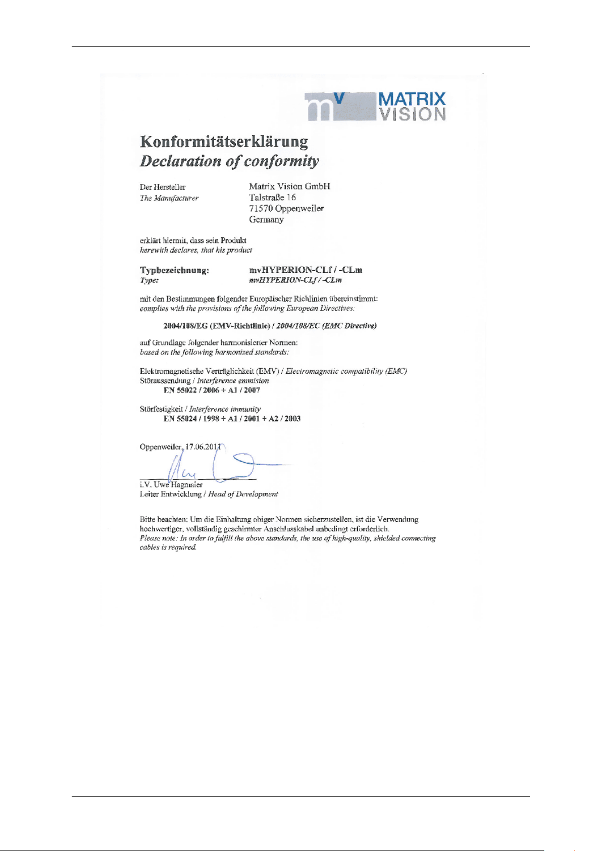
5.1 European Union Declaration of Conformity statement
The mvHYPERION-CLx is in conformity with all applicable essential requirements necessary for CE
marking. It corresponds to the EU EMC guideline 2004/108/EC based on the following harmonized
standards Electromagnetic compatibility (EMC)
• Interference emmision EN 55024:1998 + A1:2001 + A2:2003
• Interference immunity EN 55022 : 2006 + A1:2007 Class A
• Interference immunity EN 55022 : 2006 + A1:2007 Class B with modifications
EN 55022 : 2006 + A1:2007 Class B with modifications requires an CameraLink cable
with an retrofittable ferrite to be used (near to frame grabber connector) such as
– Company: Würth Elektronik Type: WE No. 742 711 31
MATRIX VISION corresponds to the EU guideline WEEE 2002/96/EG on waste electrical and electronic equipment and is registered under WEEE-Reg.-No. DE 25244305.
MATRIX VISION GmbH
Page 16
12 CONTENTS
MATRIX VISION GmbH
Page 17
5.1 European Union Declaration of Conformity statement 13
MATRIX VISION GmbH
Page 18
14 CONTENTS
6 Introduction
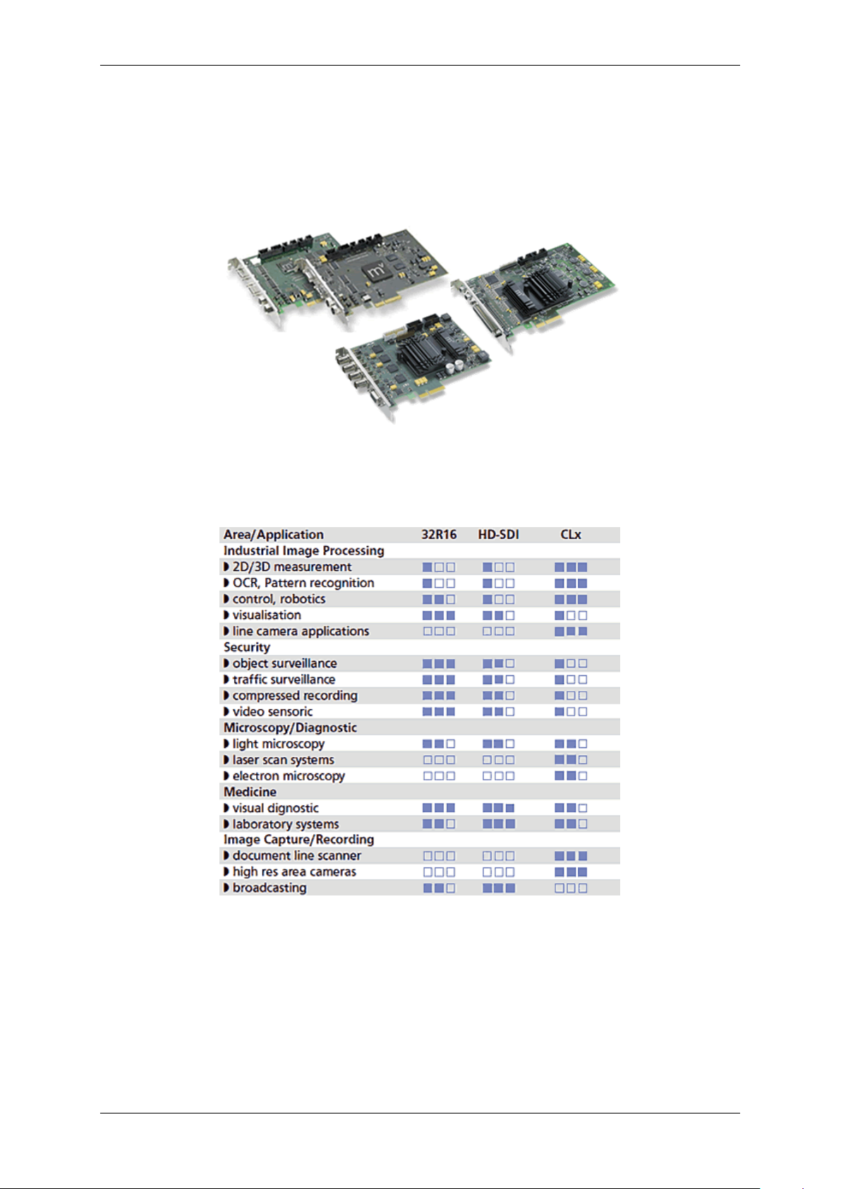
The mvHYPERION-Series are frame grabbers for the bus system PCI Express®. The mvHYPERION frame grabber
series for PCI Express® offers image processing with fast cameras using maximum capture bandwidth up to 1 G←-
B/s. Depending on the model type, the frame grabbers are suitable for high-end machine vision applications with
CameraLink cameras as well as broadcasting or surveillance solutions.
Figure 1: mvHYPERION series
There are digital inputs available for external synchronization and digital outputs for e.g. controlling a flash.
The mvHYPERION series is suitable for following application areas:
Figure 2: Application areas
6.1 What's inside and accessories
Due to the varying fields of application the mvHYPERION series is shipped without accessories. The package
contents:
• mvHYPERION frame grabber
Accessories for the mvHYPERION-CLx frame grabbers:
MATRIX VISION GmbH
Page 19

7 Quickstart 15
7 Quickstart
7.1 Hardware installation
Warning
Please take all proper Electro Static Discharge (ESD) precautions during the installation of your new hardware!
Before starting the installation, turn off your computer and all peripheral devices. Disconnect the computer from the
power supply and all necessary components.
Note
To avoid doing damage to the hardware, discharge yourself of static charge by touching e.g. the casing.
Beware of touching contacts of the frame grabber or of the computer.
• Select a free busmaster slot (PCI Express). Remove the slot's cover at the back of the computer and keep
the screw.
• Carefully insert the board into the slot by holding the board at the top and gently pushing both ends into the
slot at the same time. Press onto the upper edge of the board to make sure it is seated in the slot firmly.
• Do not force the board into the slot! You run the risk of bending the contacts. If the board does not fit easily,
pull it back out, and try again.
• Fasten the board's bracket at the back of the computer using the screws you saved from the shield.
• Put the cover back on the computer and reconnect the peripheral devices.
• Start the computer.
Warning
According to the construction, if you want to connect or disconnect a PoCL (p. 120) camera, please be sure
that the PC or the mvHYPERION frame grabber is switched off! Otherwise, during the connection, the camera
or the frame grabber could be short-circuited and possibly destroyed!
7.2 Windows
7.2.1 System Requirements
Currently supported Windows versions are:
• Microsoft Windows 7 (32-bit, 64-bit) (requires min. 2 GB main memory)
• Microsoft Windows 8.1 (32-bit, 64-bit) (requires min. 2 GB main memory)
Consecutively the installation for Windows will be described. The description for the Linux installation can be found
here: Linux (p. 20).
Note
For a correct installation of the frame grabber please install the MSI package before connecting any board to
the system. Afterwards you can install the physical board(s) and when the system starts again everything else
is done automatically.
MATRIX VISION GmbH
Page 20
16 CONTENTS
7.2.2 Software installation
All necessary drivers for Windows and Linux are contained in the mvIMPACT CD-ROM or DVD-ROM. For newer
driver versions we recommend to visit the MATRIX VISION website at www.matrix-vision.de, section Support/←-
Download/Hardware.
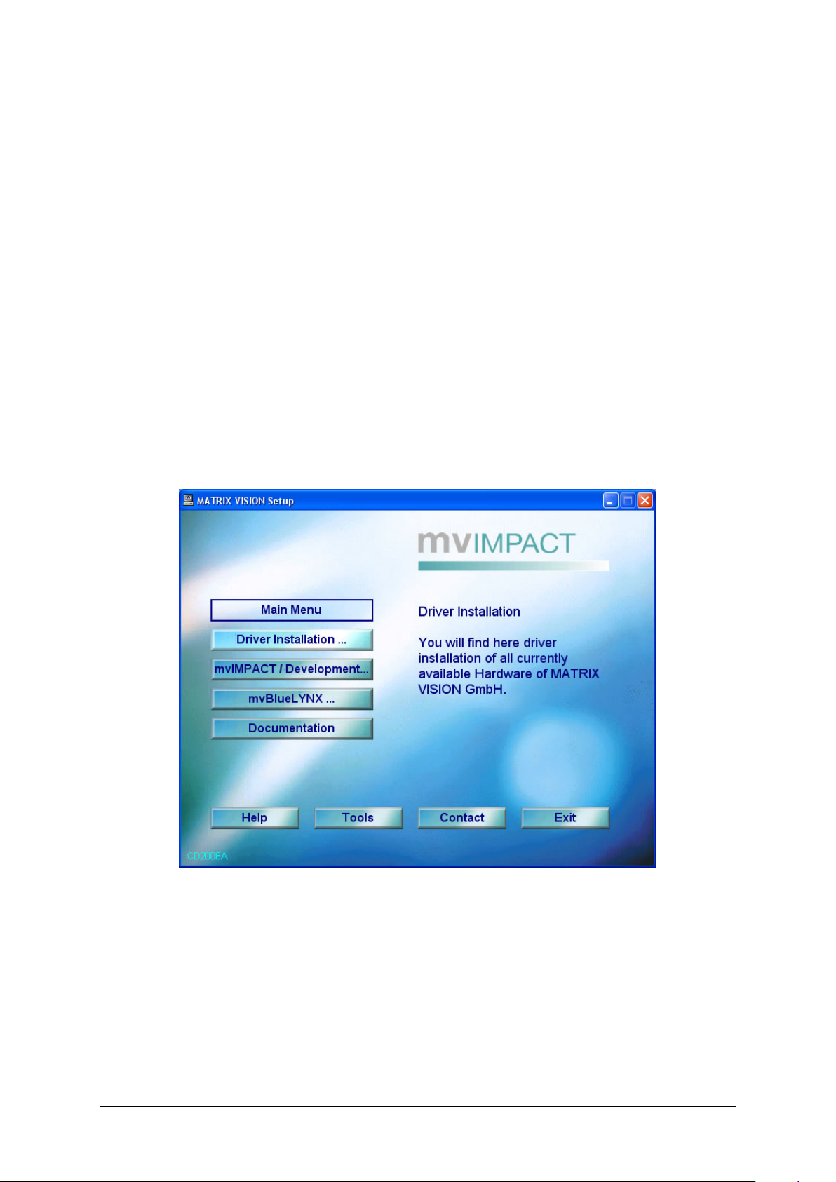
After the Hardware installation (p. 15) the boot sequence shows "Found New Hardware" and starts the Windows
Hardware Wizard. Closed this windows and insert the mvIMPACT CD-ROM or DVD-ROM into your drive and select
"Driver installation ..." and the needed mvIMPACT Acquire driver (e.g. "mvTITAN / mvGAMMA").
Figure 1: Start window
After the click on the needed driver the installation process starts.
MATRIX VISION GmbH
Page 21
7.2 Windows 17
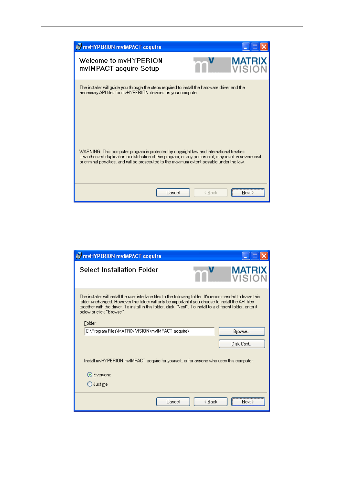
Figure 2: mvHYPERION installer - Start window
Select the folder, where you want to install the software.
Figure 3: mvHYPERION installer - Select folder
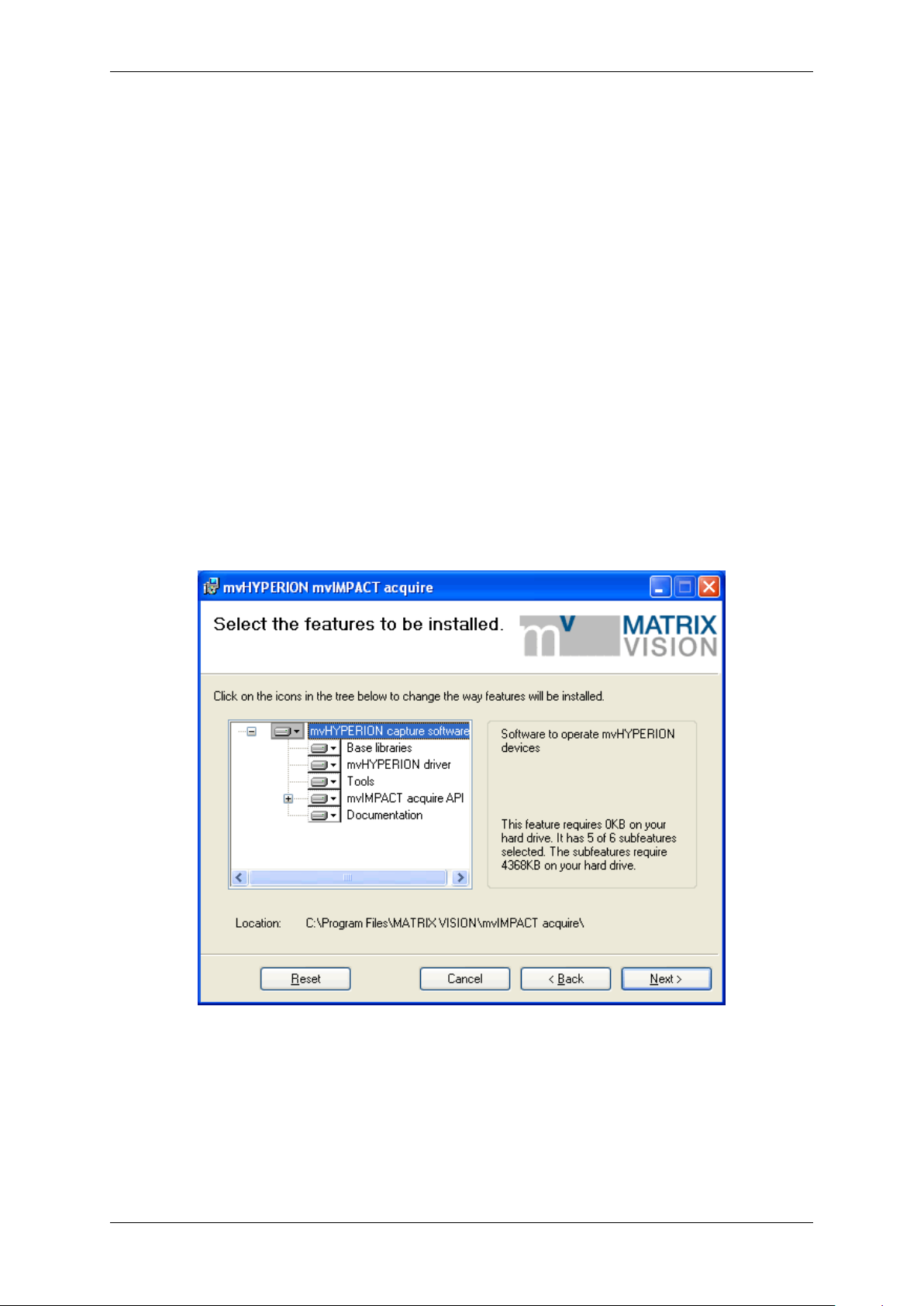
Select the features, which you want to install. Following features exist:
MATRIX VISION GmbH
Page 22
18 CONTENTS
• "Base Libraries"
This feature contains all necessary files for property handling and display. Therefore, it is not selectable.
• "mvHYPERION driver"
This is also not selectable.
• "Tools"
This feature contains tools for the frame grabber (e.g. to acquire images (wxPropView (p. 48))).
• "mvIMPACT acquire API"
The "mvIMPACT acquire API" contains the header for own programming. Additionally you can choose the
examples, which installs the sources of wxPropView (p. 48) and three mini samples. The project files of the
mini samples are for Visual C++ 7, Visual C++ 6 and Borland C Builder 6. The wxPropView (p. 48) project
exists only for Visual C++ 7.
• "Documentation"
This will install this manual as single HTML help file (.chm).
Figure 4: mvHYPERION installer - Select features
Confirm the installation by clicking "Next".
MATRIX VISION GmbH
Page 23
7.2 Windows 19
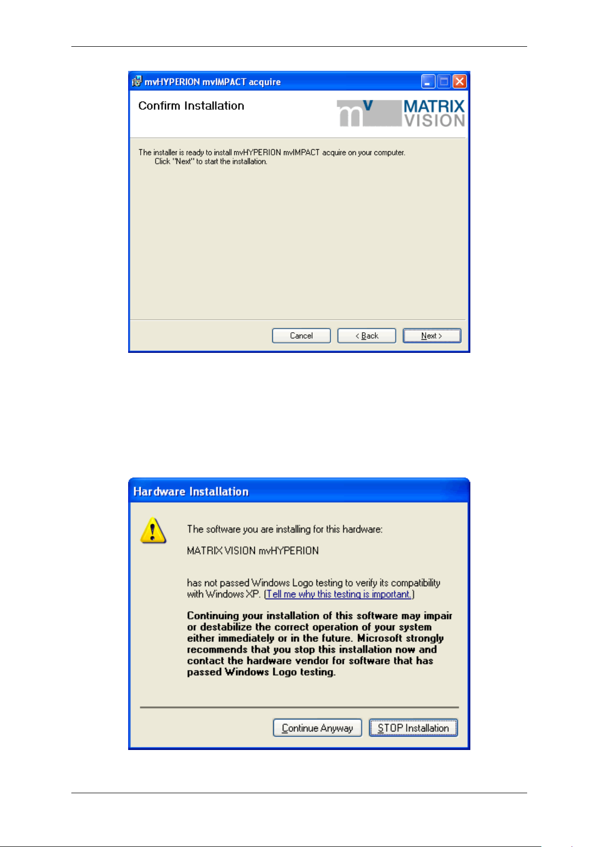
Figure 5: mvHYPERION installer - Confirm installation
The installation process copies the files to Windows. Then Windows shows a message to signal that this driver is
not checked through Microsoft. This is only an attempt to make insecure and it is recommended to ignore it.
Press "Continue Anyway" and finish the driver installation.
MATRIX VISION GmbH
Figure 6: mvHYPERION installer - Windows logo testing
Page 24
20 CONTENTS
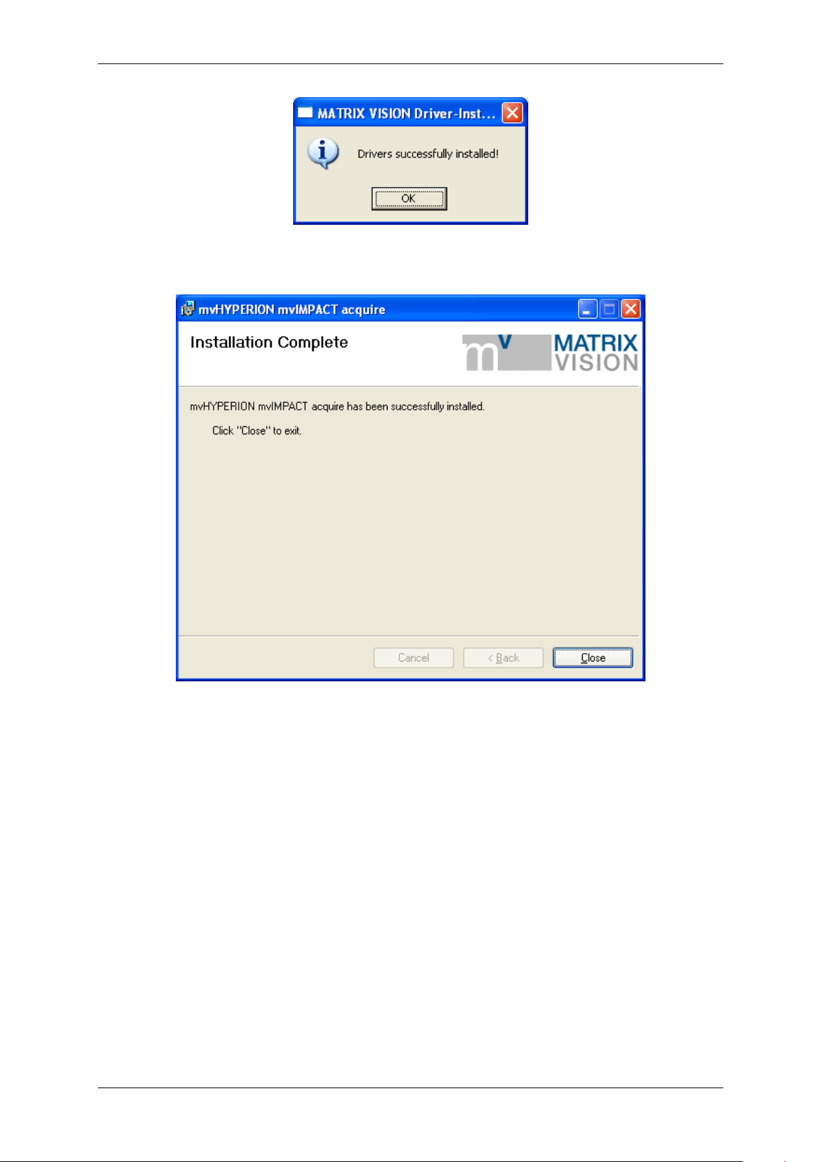
Figure 7: mvHYPERION installer - Driver successfully installed
Figure 8: mvHYPERION installer -Installation complete
After this, you have to restart the system. Afterwards, you can acquire images with the frame grabber. Simply start
the application wxPropView (p.48) (wxPropView.exe).
See also
wxPropView (p.48)
7.3 Linux
7.3.1 System Requirements
Kernel requirements
Kernel 2.6.x.
Software requirements
MATRIX VISION GmbH
Page 25

7.3 Linux 21
• Linux x86 (32-bit)
– The 32 bit version will run on a 64-bit Linux system if the other library requirements are met with 32-bit
libraries. i.e. you cannot mix 64 and 32-bit libraries and applications.
– Versions for Linux on x86-64 (64-bit), PowerPC, ARM or MIPS may be possible on request.
• GNU compiler version GCC 3.2.x or greater and associated toolchain.
Other requirements
• libexpat ( http://expat.sourceforge.net)
• Optional: wxWidgets 2.6.x (non Unicode) for the wxWidget test programs.
• Optional: udev or hotplug subsystem (see also 6. below).
As an example of which packets need to be installed, consider OpenSuSE 10.1:
• The compiler used is gcc 4.1.0 and may need to be installed. Use the "gcc" und "gcc-c++" RPMs. Other
RPMs may be installed automatically due to dependencies (e.g. make).
• libexpat will almost definitely be installed already in any software configuration. The RPM is called "expat".
• Install the wxWidgets "wxGTK" and "wxGTK-develop" RPMs. Others that will be automatically installed due
to dependencies include "wxGTK-compat" and "wxGTK-gl". Although the MATRIX VISION software does not
use the ODBC database API the SuSE version of wxWidgets has been compiled with ODBC support and the
RPM does not contain a dependency to automatically install ODBC. For this reason you must also install the
"unixODBC-devel" RPM.
• OpenSuSE 10.1 uses the udev system so a separate hotplug installation is not needed.
Hardware requirements
PC with PCI Express Single lane
Note
The driver contains libraries for Linux x86 (32 bit) or Linux 64-bit (x86_64). There are separate package files
for systems with toolchains based on GNU gcc 3.2.x - 3.3.x and those based on GNU gcc >= 3.4.x. gcc 3.1.x
may work but, in general, the older your toolchain is, the lass likely it is that it will work. Toolchainss based on
GNU gcc 2.x.x are not supported at all.
7.3.2 Installing the mvIMPACT Acquire driver
7.3.2.1 Using the installer script
To use the mvHYPERION frame grabber within Linux (grab images from it and change its settings), a driver is
needed, consisting of several libraries and several configuration files. These files are required during run time.
To develop applications that can use the mvHYPERION frame grabber, a source tree is needed, containing header
files, makefiles, samples, and a few libraries. These files are required at compile time.
Both file collections are distributed in a single package:
mvHYPERION-x86_ABI2-n.n.n.tgz
MATRIX VISION GmbH
Page 26

22 CONTENTS
1. Please start a console and change into a directory e.g. /home/username/workspace
cd /home/username/workspace
2. Copy the install script and the hardware driver to the workspace directory (e.g. from a driver CD or from the
website):
~/workspace$ cp /media/cdrom/drv/Linux/install_mvHYPERION.sh /
. && cp /media/cdrom/drv/Linux/mvHYPERION-x86_ABI2-2.14.0.tgz -t ./
3. Run the install script:
~/workspace$ ./install_mvHYPERION.sh
Note
The install script has to be executable. So please check the rights of the file.
During installation, the script will ask, if it should build all tools and samples.
You may need to enable the execute flag with
chmod a+x install_mvHYPERION.sh
The installation script checks the different packages and installs them with the respective standard packages manager (apt-get) if necessary.
Note
The installation script ("install_mvHYPERION.sh") and the archive ("mvHYPERION-x86_AB←-
I2-n.n.n.tgz") must reside in the same directory. Nothing is written to this directory during script execu-
tion, so no write access to the directory is needed in order to execute the script.
You need Internet access in case one or more of the packages on which the GenICam™ libs depend are not yet
installed on your system. In this case, the script will install these packages, and for that, Internet access is required.
The script takes two arguments, both of which are optional:
1. target directory name
2. version
The target directory name specifies where to place the driver. If the directory does not yet exist, it will be created.
The path can be either absolute or relative; i.e. the name may but need not start with "/.".
Note
This directory is only used for the files that are run time required.
The files required at compile time are always installed in "$HOME/mvimpact-acquire-n.n.n". The script
also creates a convenient softlink to this directory:
mvimpact-acquire -> mvIMPACT_acquire-2.3.2
If this argument is not specified, or is ".", the driver will be placed in the current working directory.
The version argument is entirely optional. If no version is specified, the most recent mvHYPERION-x86_AB←-
I2-n.n.n.tgz found in the current directory will be installed.
If you have also installed tools and samples, you will find them in apps. Just change into the subdirectory, for
example, "apps/mvPropView/x86" you can find the camera setup tool wxPropView (p. 48). You can find
it in subdirectory "∼/mvimpact-acquire/apps/mvPropView/x86". However, you do not always have
to start the tool from this folder. The installer script has created symbolic links so that it is enough to type in
wxPropView throughout the system to start wxPropView (p.48).
The mvIMPACT Acquire libraries look for camera definition files in the directory "mvimpact-acquire/camerafiles"
so you will need to create these directories as the "root" user using "mkdir -p ./mvimpact-acquire/camerafiles".
MATRIX VISION GmbH
Page 27

7.3 Linux 23
7.3.2.2 Doing it manually
The mvHYPERION is controlled by a number of user-space libraries. It is not necessary to compile a kernel module.
1. Logon to the PC as the "root" user or start a super user session with "su". Start a console with "root"
privileges.
2. Determine which package you need by issuing the following command in a terminal window:
gcc -v
This will display a lot of information about the GNU gcc compiler being used on your system. In case of the
version number you have to do following:
3. You can now install the mvHYPERION libraries as follows:
• create a new directory somewhere on your system.
• copy the correct package file to this directory and change into this directory with "cd".
The libraries are supplied as a "tgz" archive with the extension ".tgz".
(a) Unpack the archive using "tar" e.g.:
tar xvzf mvhyperion-x86-ABI1-1.8.4.55.tgz
or
tar xvzf mvhyperion-x86-ABI2-1.8.4.55.tgz
Note
Current versions of the ABI1 libraries were compiled using a SuSE 8.1 system for maximum compatibility with older Linux distributions. These libraries should work with all SuSE 8.x and SuSE
9.x versions as well as with Debian Sarge and older Red Hat / Fedora variants.
Current versions of the ABI2 libraries were compiled using a SuSE 10.1 system for maximum
compatibility with newer Linux distributions. These libraries should work with SuSE 10.x as well
as with Ubuntu 6.06 or newer, with up-to-date Gentoo or Fedora FC5.
(b) After installing the access libraries you will see something like the following directory structure in your
directory (dates and file sizes will differ from the list below):
drwxr-xr-x 10 root root 4096 Jan 5 15:08 .
drwxr-xr-x 23 root root 4096 Jan 4 16:33 ..
drwxr-xr-x 3 root root 4096 Jan 5 15:08 DriverBase
-rw-r--r-- 1 root root 1079 Jan 5 15:08 Makefile
drwxr-xr-x 7 root root 4096 Jan 5 15:08 apps
drwxr-xr-x 4 root root 4096 Jan 5 15:08 common
drwxr-xr-x 3 root root 4096 Jan 5 15:08 lib
drwxr-xr-x 3 root root 4096 Jan 5 15:08 mvDeviceManager
drwxr-xr-x 2 root root 4096 Jan 5 15:08 mvIMPACT_CPP
drwxr-xr-x 3 root root 4096 Jan 5 15:08 mvPropHandling
drwxr-xr-x 1 root root 4096 Jan 5 15:08 scripts
The directory "lib/x86" contains the pre-compiled 32-bit libraries for accessing the mvBlueFOX.
If 64-bit libraries are supplied they will be found in "lib/x86_64". The "apps" directory contains test
applications (source code). The directories contain headers needed to write applications for the device.
Since the libraries are not installed to a directory known to the system i.e. not in the "ldconfig"
cache you will need to tell the system where to find them by...
• using the "LD_LIBRARY_PATH" environment variable,
• or copying the libraries by hand to a system directory like "/usr/lib" (or using some symbolic
links),
• or entering the directory in "/etc/ld.so.conf" and running "ldconfig".
e.g. to start the application called "LiveSnap":
MATRIX VISION GmbH
Page 28

24 CONTENTS
Note
Please declare the device e.g. HC∗ or HC000000001
cd my_directory
LD_LIBRARY_PATH=‘pwd‘/lib/x86 apps/LiveSnap/x86/LiveSnap HC
For 64-bit it will look like this...
LD_LIBRARY_PATH=‘pwd‘/lib/x86_64 apps/LiveSnap/x86_64/LiveSnap HC
For ARM it will look like this...
LD_LIBRARY_PATH=‘pwd‘/lib/arm apps/LiveSnap/arm/LiveSnap HC
*
*
*
etc.
After installing the libraries and headers you may continue with "3." below as a normal user i.e. you do
not need to be "root" in order to compile the test applications. See also the note "4." below.
(c) To build the test applications type "make". This will attempt to build all the test applications contained
in "apps". If you have problems compiling the wxWidget library or application you may need to do one
or more of the following:
• install the wxWidget 3.x development files (headers etc.) supplied for your distribution. (See "Other
requirements" above).
• fetch, compile and install the wxWidget 3.x packet from source downloaded from the website (
http://www.wxwidgets.org).
• alter the Makefiles so as to find the wxWidget configuration script called wx-config.
The files you may need to alter are to be found here:
apps/mvPropView/Makefile.inc
You will find the compiled test programs in the subdirectories "apps/.../x86". For 64 bit systems
it will be "apps/.../x86_64". For ARM systems it will be "apps/.../arm".
If you cannot build the wxWidget test program you should, at least, be able to compile the text-based
test programs in apps/SingleCapture, apps/LiveSnap, etc.
The Makefile will also attempt to configure itself so that the mvHYPERION kernel module can be built.
You should see the following message at the end of the compile block:
=============================================================
To install the mvHYPERION kernel module now make sure that you are root and type:
make install
=============================================================
If you are not already logged in as the "root" user you must now use "su" to change users and type
"make install". On an Ubuntu system you might try "sudo make install". The kernel
module will now be built and installed.
Now you will have to tell your system to use this kernel module and to associate it with a device
node. To do this you need to edit the file "/etc/modprobe.conf". Depending on your system
you may have a directory called "/etc/modules.d/", where you can put files that are included
automatically in "/etc/modprobe.conf". Other systems (e.g. older SuSE) use a file called
"/etc/modprobe.conf.local" which the user may alter. Which ever way you do it, you need
to add some lines like this:
alias char-major-64 hyperion
options hyperion major_dev_num=64
Afterwards, please use "depmod -a" to tell the system about this change. The lines above tell the
system to use a device called "/dev/hyperion" with a major number of 64.
(d) If you are using a system with an up-to-date version of udev you might be interested in the file "←-
Scripts/50-udev-hyperion.rules". By including this file in your udev rules directory you can tell your
system to create a device node for the mvHYPERION automatically when loading the kernel module.←-
You will need to edit the file to fit your system. As delivered, all entries are commented out.
If you do not use udev then you will have to create a device node yourself by hand. For example, you
could do the following to use major device number 64:
mknod /dev/hyperion c 64 0
MATRIX VISION GmbH
Page 29

7.4 Connecting a camera 25
If you have more than one mvHYPERION in your PC you will need a device node per card:
mknod /dev/hyperion0 c 64 0
mknod /dev/hyperion1 c 64 1
mknod /dev/hyperion2 c 64 2
mknod /dev/hyperion3 c 64 3
(e) The mvIMPACT Acquire libraries look for camera definition files in the directory "/etc/matrix-vision/mvimpact-acquire/camerafiles"
so you will need to create these directories as the "root" user using "mkdir -p /etc/matrix-vision/mvimpact-acquire/camerafiles".
You should download the camera definitions for your camera from the MATRIX VISION website and
copy them to this directory.
7.4 Connecting a camera
To connect a camera, for example via CameraLink cable to the mvHYPERION-CLx frame grabber, please do the
following:
• Connect the cable from the camera (labeled with e.g. Data channel 1) to the first connector J1 of the mvH←-
YPERION frame grabber.
• Optionally, if you are using a Medium or Full, connect the cable from the camera (labeled with e.g. Data
channel 2) to the second connector J2 of the mvHYPERION.
• Optionally, use the connector J3 to power the camera.
Make sure that you do not mix up the channels. For this, please have a look at chapter Technical data (p. 28),
where to find the specific connectors.
• Afterwards, start wxPropView (p.48) and choose the "Generic" camera definition.
• Now, press the Live button - at this point you should see something from the camera.
• Then, create a new camera definition as described in Working with camera descriptions (p. 71).
• Finally, export the new camera definition and choose it in "wxPropView -> ImageSetting -> Camera -> Type".
7.5 Settings behavior during startup
Settings contain all the parameters that are needed to prepare and program the device for the image capture. Every
image can be captured with completely different set of parameters. In almost every case, these parameters are
accessible via a property offered by the device driver. A setting e.g. might contain
• the gain to be applied to the analog to digital conversion process for analog video sources or
• the AOI to be captured from the incoming image data.
So for the user a setting is the one an only place where all the necessary modifications can be applied to achieve
the desired form of data acquisition.
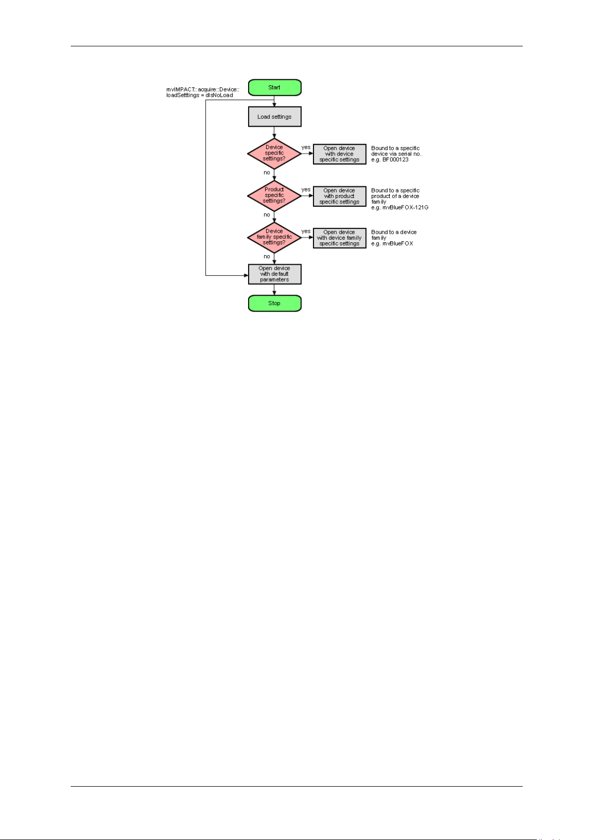
Now, whenever a device is opened, the driver will execute following procedure:
MATRIX VISION GmbH
Page 30
26 CONTENTS
Figure 9: wxPropView - Device setting start procedure
• Please note that each setting location step in the figure from above internally contains two search steps. First
the framework will try to locate a setting with user scope and if this can't be located, the same setting will be
searched with global (system-wide) scope. Under Windows® this e.g. will access either the HKEY_CURR←-
ENT_USER or (in the second step) the HKEY_LOCAL_MACHINE branch in the Registry.
• Whenever storing a product specific setting, the device specific setting of the device used for storing will be
deleted (if existing). So when the user is currently working with a device 'VD000001' belonging to the product
group 'VirtualDevice' and there is a setting exclusively for this device storing a product specific setting now will
automatically delete the setting for 'VD000001'. Otherwise a product specific setting would never be loaded
as a device specific setting will always be found first.
• The very same thing will also happen when opening a device from any other application! wxPropView (p. 48)
does not behave in a special way but only acts as an arbitrary user application.
• Whenever storing a device family specific setting, the device specific or product specific setting of the device
used for storing will be deleted (if existing). See above to find out why.
• Under Windows® the driver will not look for a matching XML file during start-up automatically as the native
storage location for settings is the Windows® Registry. This must be loaded explicitly by the user by using
the appropriate API function offered by the SDK. However, under Linux XML files are the only setting formats
understood by the driver framework thus here the driver will also look for them at start-up. The device specific
setting will be an XML file with the serial number of the device as the file name, the product specific setting
will be an XML file with the product string as the filename, the device family specific setting will be an XML
file with the device family name as the file name. All other XML files containing settings will be ignored!
• Only the data contained in the lists displayed as "Image Setting", "Digital I/O" and "Device
Specific Data" under wxPropView (p.48) will be stored in these settings!
• Restoring of settings previously stored works in a similar way. After a device has been opened the settings
will be loaded automatically as described above.
• A detailed description of the individual properties offered by a device will not be provided here but can be
found in the C++ API reference, where descriptions for all properties relevant for the user (grouped together in
classes sorted by topic) can be found. As wxPropView (p.48) doesn't introduce new functionality but simply
evaluates the list of features offered by the device driver and lists them any modification made using the GUI
MATRIX VISION GmbH
Page 31

7.5 Settings behavior during startup 27
controls just calls the underlying function needed to write to the selected component. wxPropView (p. 48)
also doesn't know about the type of component or e.g. the list of allowed values for a property. This again is
information delivered by the driver and therefore can be queried by the user as well without the need to have
special inside information. One version of the tool will always be delivered in source so it can be used as a
reference to find out how to get the desired information from the device driver.
MATRIX VISION GmbH
Page 32

28 CONTENTS
8 Technical data
8.1 mvHYPERION-CLx
8.1.1 Block diagrams
The following block diagrams show schematically how the different mvHYPERION-CLx are designed.
8.1.2 Connectors
Figure 1: mvHYPERION-CLb block diagram | mvHYPERION-CLe block diagram
Figure 2: mvHYPERION-CLm block diagram | mvHYPERION-CLf block diagram
The mvHYPERION supports the serial communication over CameraLink™ cable as described in the Camera←-
Link™ specification. The driver offers a serial interface without the need of a host PC's COM port. During the
boot sequence of the operating system the serial interface is initialized. Normally, manufacturers of CameraLink™
cameras provide software to parameterize the camera. If this software abides by the specification, it will access our
serial interface driver automatically.
MATRIX VISION GmbH
Page 33

8.1 mvHYPERION-CLx 29
Note
For Linux there is no CameraLink™ specified library. Therefore we ship CameraLink™ compliant library
libclserMV.so which can be found in the lib directory.
Figure 3: mvHYPERION-CLe
8.1.2.1 Status LEDs
Figure 4: mvHYPERION-CLf
Figure 5: Rev. 1.x
LED Name Description
D9 FPGA state Green: FPGA is loaded
D10 PCI Express® connection state Green: No problem with connection
MATRIX VISION GmbH
Figure 6: Rev. 3.x
Page 34

30 CONTENTS
LED Name Description
D9 FPGA state Green: FPGA is loaded
D10 PCI Express® x4 connection state Green: No problem with connection (PCI Express host supports 4
lanes)
D24 PCI Express® x1 connection state Green: No problem with connection (PCI Express host supports 1
lanes)
8.1.2.2 Use of J1..J4
Connector usage mvHYPERION
-CLb -CLe -CLm -CLf
J1 Camera 1 (BASE 1) Camera 1 (BASE 1) Camera 1 (BASE 1) Camera 1 (BASE 1)
J2 - Camera 1 (MEDI←-
UM 1) or camera 2
(BASE 2)
J3 Camera 1 trigger
/ sync / strobe /
power connector
Camera 1 trigger
/ sync / strobe /
power connector
J4 - Camera 2 trigger
/ sync / strobe /
power connector
Camera 1 (MEDI←-
UM 1) or camera 2
(BASE 2)
Camera 1 trigger
/ sync / strobe /
power connector
Camera 2 trigger
/ sync / strobe /
power connector
Camera 1 (MEDI←-
UM 1) or camera 1
(FULL 1)
Camera 1 trigger
/ sync / strobe /
power connector
Additional connector with trigger
/ sync / strobe /
power
8.1.2.3 Pinning J1/J2 (CL configuration)
Figure 7: Mini CameraLink connector (female)
Pin J1/J2 (used as) BASE (used as) MEDIUM (used as) FULL
Signal Type Signal Type Signal Type
1 Internal
shield or
Power
14 Internal
shield
PoCL (p. 120)
(+12V or
Ground)
Internal
shield or
Power
Ground Internal
shield
PoCL (p. 120)
(+12V or
Ground)
Internal
shield or
Power
Ground Internal
shield
PoCL (p. 120)
(+12V or
Ground)
Ground
25 X0- Input 1- Y0- Input 1- Y0- Input 1-
12 X0+ Input 1+ Y0+ Input 1+ Y0+ Input 1+
24 X1- Input 2- Y1- Input 2- Y1- Input 2-
11 X1+ Input 2+ Y1+ Input 2+ Y1+ Input 2+
23 X2- Input 3- Y2- Input 3- Y2- Input 3-
10 X2+ Input 3+ Y2+ Input 3+ Y2+ Input 3+
22 Xclk- Input 4- Yclk- Input 4- Yclk- Input 4-
9 Xclk+ Input 4+ Yclk+ Input 4+ Yclk+ Input 4+
21 X3- Input 5- Y3- Input 5- Y3- Input 5-
8 X3+ Input 5+ Y3+ Input 5+ Y3+ Input 5+
20 SerTC+ Output 6+ Not used - - Not used, In-
put 6+
MATRIX VISION GmbH
Page 35

8.1 mvHYPERION-CLx 31
7 SerTC- Output 6- Not used - - Not used, In-
put 6-
19 SerTFG- Output 7- Not used 100 Ohm ter-
Z0- Input 7-
minated
6 SerTFG+ Output 7+ Not used 100 Ohm ter-
Z0+ Input 7+
minated
18 CC1- Output 8- Not used 100 Ohm ter-
Z1- Input 8-
minated
5 CC1+ Output 8+ Not used 100 Ohm ter-
Z1+ Input 8+
minated
17 CC2+ Output 9+ Not used 100 Ohm ter-
Z2- Input 9-
minated
4 CC2- Output 9- Not used 100 Ohm ter-
Z2+ Input 9+
minated
16 CC3- Output 10- Not used 100 Ohm ter-
Zclk- Input 10-
minated
3 CC3+ Output 10+ Not used 100 Ohm ter-
Zclk+ Input 10+
minated
15 CC4+ Output 11+ Not used 100 Ohm ter-
Z3- Input 11-
minated
2 CC4- Output 11- Not used 100 Ohm ter-
Z3+ Input 11+
minated
13 Internal
shield
26 Internal
shield
Ground Internal
shield
Ground Internal
shield or
Power
Ground Internal
shield
PoCL (p. 120)
(+12V or
Ground)
Internal
shield or
Power
Ground
PoCL (p. 120)
(+12V or
Ground)
8.1.2.4 Pinning J3 (Camera 1: Trigger/Flash/Power)
Figure 8: 8-pin Binder Line 711 (female)
Pin. Signal Cable (KS99-0285)
1 +12 V DC (0.7A/2A) (camera power) Red
2 Trigger-Out1 (+) -> Collector White
3 Trigger-Out1 (-) -> Emitter Brown
4 Trigger-In1 (+) -> Anode Green
5 Trigger-In1 (-) -> Cathode Yellow
6 Sync-In1 (+) -> Anode Gray
7 Sync-In1 (-) -> Cathode Pink
8 GND (camera power) Blue
8.1.2.5 Pinning J4 (Camera 2: Trigger/Flash/Power)
MATRIX VISION GmbH
Pin. Signal Cable (KS99-0285)
1 +12 V DC (0.7A/2A) (camera power) Red
Page 36

32 CONTENTS
2 Strobe-Out2 (+) -> Collector White
3 Strobe-Out2 (-) -> Emitter Brown
4 Trigger-In2 (+) -> Anode Green
5 Trigger-In2 (-) -> Cathode Yellow
6 Sync-In2 (+) -> Anode Gray
7 Sync-In2 (-) -> Cathode Pink
8 GND (camera power) Blue
Recommended plugs for 8-pin Binder series 711:
• 711: Binder ordering no. 99-0479-100-08 / 99-0479-102-08
Detailed information: http://www.binder-connector.de
8.1.2.6 Pinning J5 (Power supply (floppy))
You can connect a free power supply cable for floppy drives on connector J5 to increase the available current on the
power supply pins on J3 and J4 to 2A.
Pin Signal
1 +12 V
2 Ground
3 Ground
4 Not connected
8.1.2.7 Pinning J6 (internal digital I/Os)
Figure 9: J6
Pin Signal Signal direction
1..5 used internally (do not connect!)
6 Ground Ground
7 +5V out +5V DC power supply
8 +3.3V out +3.3V DC power supply
9..12 GPIN0..3 LVTTL(3.3V) input.
not 5V tolerant!
13..16 GPOUT0..3 LVTTL(3.3V) output.
not 5V tolerant!
17 Ground Ground
18 +12V DC Out +12V DC power supply
19 +12V DC Out +12V DC power supply
20 Ground Ground
MATRIX VISION GmbH
Page 37

8.1 mvHYPERION-CLx 33
IDC multi-pin connector 2 x 10 Pol RM 2.54 x 2.54 mm.
Note
Pins are not opto-isolated, feature no EMC filter and are not protected against overload and overvoltage.
Digital signals (pins 9-16) are LVTTL signals and not 5V tolerant. Failure to take this into account may
result in the destruction of the board.
Attention
Without an additional card with corresponding snubbers these signals must not conducted!
8.1.2.8 Switches
mvHYPERION
-CLb -CLe -CLm CLf
Switch S1
Flash memory
Position Comment
Def. Case of need FPGA version is
loaded (write protected)
User FPGA version, which can be
updated, is loaded.
Switch S2
Switch between TTL (5V) and PLC (24V) as well as Trigger and Sync on connector J3
Position Comment
Trigger (1) Sync (2)
on TTL (5V) TTL (5V)
off PLC (24V) PLC (24V)
Switch S3
Switch between TTL (5V) and PLC (24V) as well as Trigger and Sync on connector J4
Position Comment
Trigger (1) Sync (2)
on TTL (5V) TTL (5V)
off PLC (24V) PLC (24V)
MATRIX VISION GmbH
Page 38

34 CONTENTS
8.1.2.9 Digital I/Os
Figure 10: Trigger-In mvHYPERION-CLx
MATRIX VISION GmbH
Page 39

8.1 mvHYPERION-CLx 35
Figure 11: Trigger-In mvHYPERION-CLx
Figure 12: Trigger-Out mvHYPERION-CLx
8.1.2.9.1 Opto-isolated digital inputs
TTL compatible threshold (standard):
VIH,
25V (VIH, max = maximum input voltage, which causes an active signal)
max:
VIH,
4V (VIH, min = minimum input voltage, which causes an active signal)
min:
VIH, typ 5V..24V (VIH, typ = typical input voltage, which causes an active signal)
VIL, max 1V (VIL, max = maximum input voltage, which causes an inactive signal)
VIL, min -30V (VIL, min = minimum input voltage, which causes an active signal)
Ii, max 20mA (li, max = maximum input current)
PLC compatible threshold (additionally external protective circuit of Z diodes necessary):
VIH,
37V (VIH, max = maximum input voltage, which causes an active signal)
max:
VIH,
15V (VIH, min = minimum input voltage, which causes an active signal)
min:
VIL, max 13V (VIL, max = maximum input voltage, which causes an inactive signal)
VIL, min -30V (VIL, min = minimum input voltage, which causes an active signal)
MATRIX VISION GmbH
Page 40

36 CONTENTS
Ii, max 20mA (li, max = maximum input current -> controlled internally)
Max. input frequency of the opto-isolated inputs: 10MHz
An additional series resistor is not necessary at the inputs. The inputs own an internal current limitation and are
protected up to -30V against polarity.
8.1.2.9.2 Opto-isolated digital output
Attention
The output is not overload protected and doesn't feature a free-wheeling diode!
There are following conditions:
VCEO, max
35V (VCEO, max = max. voltage between C (pin 2) and E (pin 3) on opened transistor)
(typ):
VECO, max: 0.3V (VCEO, max = max. voltage between E (pin 3) and C (pin 2) on opened transistor)
VCE, sat 1.5V (VCE, sat = max. voltage between C (pin 2) and E (pin 3) on active transistor and
IC, max)
IC, max 200mA (IC, max. = max. current which is allowed to flow to the direction of C (pin 2))
tr, max 5us (rise (on) time)
tf, max 2ms (fall (off) time HW rev. 1.xx)
tf, max 20us (fall (off) time HW rev. 2.00)
The output is not protected against overvoltage, overload and polarity reversal.
8.1.2.10 Digital I/Os (J6)
8.1.2.10.1 LVTTL-IN parameters (GPIN3..0)
VIH,
3.9V...2.0V (VIH, max = permissible input voltage, which causes an active signal)
max..min:
VIL,
0.8V...-0.3V (VIL, max = permissible input voltage, which causes an inactive signal)
max..min:
Iin, max: ±0,1mA (Iin,max = maximum input current)
8.1.2.10.2 LVTTL-OUT parameters (GPOUT3..0 and I2C-SCL)
OH,
2.4V (OH, mix = minimum active output voltage with Iout = -2mA output current)
min:
OL,
0.4V (OL, max = maximum inactive output voltage with Iout = +2mA output current)
max:
Iout,
±4mA (Iout, max = maximum output current)
max:
8.1.2.10.3 LVTTL-OC parameters (I2C-SDA)
MATRIX VISION GmbH
Page 41

8.1 mvHYPERION-CLx 37
VIH,
3.9V...2.0V (VIH, max = permissible input voltage, which causes an active signal)
max..min:
VIL,
0.8V...-0.3V (VIL, max = permissible input voltage, which causes an inactive signal)
max..min:
IOL, max: 0.5V (IOL, max = maximum output voltage with internal driven inactive signal)
IL, max: 3.5V (OL, max = maximum input voltage with internal driven inactive signal)
8.1.3 Components
mvHYPERION
-CLb -CLe -CLm -CLf
Video input
Signal format CameraLink ™ (MiniCL)
Video input 1x BASE 2x BASE or 1x M←-
EDIUM
2x BASE or 1x M←-
EDIUM
1x BASE or 1x M←-
EDIUM or 1x FULL
Max. CL clock 85 MHz
Supported CL
1.2
specification
Resolution
Horizontal / vertical 64 K / not limited
Pixel formats
RGB 24 / 30 / 32 bit
Gray 8 / 10 / 12 / 14 / 16 bit
Interface
Bus PCI Express® x1 PCI Express® x4
Continuous data
Max. 200 MB/s Max. 620 MB/s
rate
Peak data rate Max. 250 MB/s Max. 1 GB/s
Payload size Up to 512 Bytes Up to 256 Bytes
Digital in and outputs
Trigger-In 1, differential, opto-
2, differential, opto-isolated, 5 to 24V
isolated, 5 to 24V
Strobe-Out 1, differential, opto-
2, differential, opto-isolated, max. 30V, 100mA
isolated, max. 30V,
100mA
Sync-In 1, differential, opto-
2, differential, opto-isolated, 5 to 24V
isolated, 5 to 24V
Current consumption
PCIe 3.3V Max. 1A
PCIe 12V Max. 0.05A + camera power
Camera supply Via PCI Express® 12V max. 0.7A fused Via PCI Express® 12V max. 2A fused
Via additional floppy power plug up to 2A -
Environmental conditions
MATRIX VISION GmbH
Page 42

38 CONTENTS
Ambient tempera-
0 up to 45 C 0 up to 60 C 0 up to 45 C
ture
Storage tempera-
-20 up to 70 C
ture
Humidity 10 up to 90 % non-condensing
Dimensions
Length 147 mm 155 mm
Width 95 mm 111.5 mm
8.1.4 Device Feature And Property Lists
8.1.4.1 mvHYPERION-CLm
8.2 mvHYPERION-32R16
8.2.1 Block diagram
The following block diagram shows schematically how the mvHYPERION-32R16 is designed.
Figure 13: mvHYPERION-32R16 block diagram
MATRIX VISION GmbH
Page 43

8.2 mvHYPERION-32R16 39
8.2.2 Connectors
8.2.2.1 Status LEDs
LED Name Description
1 PCI Express® connection state Green: No problem with connection
2 FPGA state Green: FPGA is loaded
8.2.2.2 Pinning J1 (68-pol connector)
Pin Signal Note Pin Signal Note
1 Power 5V 35 GND (G)
2 VIDEO_15 36 GND (G)
3 VIDEO30 Not used 37 GND (G)
4 VIDEO_14 38 GND (G)
5 VIDEO29 Not used 39 GND (G)
Figure 14: mvHYPERION-32R16
Figure 15: J1
MATRIX VISION GmbH
Page 44

40 CONTENTS
6 VIDEO_13 40 GND (G)
7 VIDEO28 Not used 41 GND (G)
8 VIDEO_12 42 GND (G)
9 VIDEO27 Not used 43 GND (G)
10 VIDEO_11 44 GND (G)
11 VIDEO26 Not used 45 GND (G)
12 VIDEO_10 46 GND (G)
13 VIDEO25 Not used 47 GND (G)
14 VIDEO_9 48 GND (G)
15 VIDEO24 Not used 49 GND (G)
16 VIDEO_8 50 GND (G)
17 VIDEO23 Not used 51 GND (G)
18 VIDEO_7 52 GND (G)
19 VIDEO22 Not used 53 GND (G)
20 VIDEO_6 54 GND (G)
21 VIDEO21 Not used 55 GND (G)
22 VIDEO_5 56 GND (G)
23 VIDEO20 Not used 57 GND (G)
24 VIDEO_4 58 GND (G)
25 VIDEO19 Not used 59 GND (G)
26 VIDEO_3 60 GND (G)
27 VIDEO18 Not used 61 GND (G)
28 VIDEO_2 62 GND (G)
29 VIDEO17 Not used 63 GND (G)
30 VIDEO_1 64 GND (G)
31 VIDEO16 Not used 65 GND (G)
32 VIDEO_0 66 GND (G)
33 RS-485 TXP 67 RS-485 TXN
34 RS-485 RXP 68 RS-485 RXN
Manufacturer of the connector: Nexus
Part No.: 32040168R
8.2.2.3 Audio
Both audio connectors (left and right) are Cinch connectors.
8.2.3 Components
mvHYPERION
-32R16
Video
Input signal Interlaced, gray scale
Interlaced, color
50Hz PAL
60Hz NTSC
Number of video inputs 32
MATRIX VISION GmbH
Page 45

8.3 mvHYPERION-HD-SDI 41
Audio
2 (Cinch)
Resolution
Digitalization According to D1 digital video format
Storage According to D1 digital video format
Memory format YUV 4:2:2 packed/planar
Interface
Bus PCI Express® x4
Continuous data rate Max. 640 MB/s
Peak data rate Max. 1 GB/s
Payload size Up to 256 Bytes
Current consumption
PCIe 3.3V 5W
PCIe 12V 4W
Environmental conditions
Ambient temperature 0 up to 45 C
Storage temperature -20 up to 70 C
Humidity 10 up to 90 % non-condensing
Dimensions
Length 170 mm
Width 111.1 mm
8.3 mvHYPERION-HD-SDI
8.3.1 Block diagram
The following block diagram shows schematically how the mvHYPERION-HD-SDI is designed.
MATRIX VISION GmbH
Page 46

42 CONTENTS
8.3.2 Connectors
8.3.2.1 Use of J1..J2
Figure 16: mvHYPERION-HD-SDI-2 block diagram
Figure 17: mvHYPERION-HD-SDI-2
Connector usage mvHYPERION
-HD-SDI-2
J1 Camera 1 (3G/HD-SDI signal)
J2 Camera 2 (3G/HD-SDI signal)
MATRIX VISION GmbH
Page 47

8.3 mvHYPERION-HD-SDI 43
8.3.2.2 Pinning J5 (15-pol D-SUB/HD connector)
Figure 18: J5
Pin Signal Signal direction Level
1 Sync-Out 1 (Trilevel, 75R) OUT 1Vss (75R)
2 Sync-Out 2 (Trilevel, 75R) OUT 1Vss (75R)
3 Sync-Out 3 (Trilevel, 75R) OUT 1Vss (75R)
4 ID2 IN/OUT TTL (open collector)
5 Digital Ground RS-485 GND -
6 Ground Sync-Out 1 GND -
7 Ground Sync-Out 2 GND -
8 Ground Sync-Out 3 GND -
9 Camera Power Supply OUT +5VDC / >=10W (optional +12VDC)
10 Ground Sync GND -
11 ID0 IN/OUT TTL (open collector)
12 RS-485 TRX- IN/OUT RS48513 C/HSync-Out OUT TTL (push pull)
14 VSync-Out OUT TTL (push pull)
15 RS-485 TRX+ IN/OUT RS485+
8.3.2.3 Pinning J6 (internal digital I/Os)
Pin Signal Signal direction Level
1 NC - 2 Ground GND 3 SCL IN/OUT LVTTL
4 Ground GND 5 SDA IN/OUT LVTTL
6 Ground GND 7 +5V power supply OUT +5V DC
8 +3.3V power supply OUT +3.3V DC
12..9 GPIN3..0 IN LVTTL(3.3V) input.
16..13 GPOUT3..0 OUT LVTTL(3.3V) output.
17 Ground GND 18 +12V power supply OUT +12V DC
19 +12V power supply OUT +12V DC
20 Ground GND -
Figure 19: J6
not 5V tolerant!
not 5V tolerant!
MATRIX VISION GmbH
Page 48

44 CONTENTS
IDC multi-pin connector 2 x 10 Pol RM 2.54 x 2.54 mm.
Note
Pins are not opto-isolated, feature no EMC filter and are not protected against overload and overvoltage.
Digital signals (pins 9-16) are LVTTL signals and not 5V tolerant. Failure to take this into account may
result in the destruction of the board.
Attention
Without an additional card with corresponding snubbers these signals must not conducted!
8.3.3 Components
mvHYPERION
-HD-SDI-2
supported signal formats
MATRIX VISION GmbH
Page 49

8.3 mvHYPERION-HD-SDI 45
Acquisition of 2 independent standard
HD-SDI signals or one standard 3G-SDI signal
Max.
chan-
Format Frequency
(fps)
nels
2 1080p 23.←-
98,
24,
25,
29.←-
97,
30
1 1080p 50,
59.←-
94,
60
2 720p 23.←-
98,
24,
25,
29.←-
97,
30,
50,
59.←-
94,
60
2 1080i/psf50,
59.←-
94,
60
Video
timing/
data
mapping
S←-
M←-
PTE
ST
274
S←-
M←-
PTE
ST
425
/
Level
A
S←-
M←-
PTE
ST
296
S←-
M←-
PTE
ST
274
Physical
layer
S←-
M←-
PTE
ST
2921
S←-
M←-
PTE
ST
4241
S←-
M←-
PTE
ST
2921
S←-
M←-
PTE
ST
2921
Standard
data
Y←-
U←-
V4←-
:2:2
(2x10←-
Bit)
Y←-
U←-
V4←-
:2:2
(2x10←-
Bit)
Y←-
U←-
V4←-
:2:2
(2x10←-
Bit)
Y←-
U←-
V4←-
:2:2
(2x10←-
Bit)
Comment
Only
channel
0
supported;
Firmware
version
>=
86
required.
The
host
system
puts
the
two
fields
together
to
one
frame.
MATRIX VISION GmbH
Page 50

46 CONTENTS
Acquisition of up to 2 non-standard HD/3G-SDI signals
Max.
channels
2 1080p 23.←-
2 1080p 50,
1 1080p 50,
1 1080p 50(100),
2 720p 23.←-
Format Frequency
(fps)
98,
24,
25,
29.←-
97,
30
59.←-
94,
60
59.←-
94,
60
59.←-
94(119.←-
88),
60(120)
98,
24,
25,
29.←-
97,
30,
Video
timing/
data
mapping
S←-
M←-
PTE
ST
274
S←-
M←-
PTE
ST
425
/
Level
A
S←-
M←-
PTE
ST
425
/
Level
A
S←-
M←-
PTE
ST
425
/
Level
A
S←-
M←-
PTE
ST
296
Physical
layer
S←-
M←-
PTE
ST
2921
S←-
M←-
PTE
ST
4241
S←-
M←-
PTE
ST
4241
S←-
M←-
PTE
ST
4241
S←-
M←-
PTE
ST
2921
Nonstandard
data
Raw(2k),
Raw(12←-
Bit)
Raw(12←-
Bit)
Raw(2k)Only
Raw(2in1)2
Raw(2k),
Raw(12←-
Bit)
MATRIX VISION GmbH
Comment
Firmware
version
>=
86
required.
channel
0
supported;
Firmware
version
>=
86
required.
frames
in
one
double
image
height;
Only
channel
0
supported;
Firmware
version
>=
86
required.
Page 51

8.3 mvHYPERION-HD-SDI 47
Interface
Bus PCI Express® x4
Continuous data rate Max. 640 MB/s
Peak data rate Max. 1 GB/s
Payload size Up to 256 Bytes
Current consumption
PCIe 3.3V Max. 1A
PCIe 12V Max. 0.05A + camera power
Camera supply Via PCI Express® 12V fused
Environmental conditions
Ambient temperature 0 up to 45 C
Storage temperature -20 up to 70 C
Humidity 10 up to 90 % non-condensing
Dimensions
Length 155 mm
Width 111.1 mm
MATRIX VISION GmbH
Page 52

48 CONTENTS
9 Application Usage
9.1 wxPropView
wxPropView (p. 48) is an interactive GUI tool to acquire images and to configure the device and to display and
modify the device properties of MATRIX VISION GmbH hardware. After the installation you can find wxPropView
(p. 48)
• as an icon with the name "wxPropView" on the desktop (Windows) or
• in "∼/mvimpact-acquire/apps/mvPropView/x86" (Linux).
wxPropView - Introduction:
https://www.matrix-vision.com/tl_files/mv11/trainings/wxPropView/wx←-
PropView_Introduction/index.html
9.1.1 How to work with wxPropView
wxPropView - Working with wxPropView:
https://www.matrix-vision.com/tl_files/mv11/trainings/wxPropView/wx←-
PropView_WorkingWith/index.html
9.1.1.1 First View of wxPropView
wxPropView (p.48) consists of several areas:
MATRIX VISION GmbH
Page 53

9.1 wxPropView 49
Figure 1: wxPropView started
• "Menu Bar"
(to work with wxPropView (p.48) using the menu)
• "Upper Tool Bar"
(to select and initialize a device, acquire images, play a recorder sequence)
• "Left Tool Bar"
(to hide and show parts of the GUI)
• "Status Tool Bar"
• "Main Window" with
– "Grid"
(tree control with the device settings accessible by the user)
– "Display"
(for the acquired images)
– "Analysis"
(information about whole images or an AOI)
By clicking on F1 you will get the HELP dialog.
Now, you can initialize a device by
MATRIX VISION GmbH
Page 54

50 CONTENTS
• selecting it in the drop down list in the "Upper Tool Bar" and
• clicking on "Use".
After having successfully initialized a device the tree control in the lower left part of the "Main Window" will display
the properties (settings or parameters) (according to the "interface layout") accessible by the user.
You've also got the possibility to set your "User Experience". According to the chosen experience, the level of
visibility is different:
• Beginner (basic camera settings/properties are visible)
• Expert (e.g. all advanced image processing are visible)
• Guru (all settings/properties are visible)
Properties displayed in light grey cannot be modified by the user. Only the properties, which actually have an impact
on the resulting image, will be visible. Therefore, certain properties might appear or disappear when modifying
another properties.
To permanently commit a modification made with the keyboard the ENTER must be pressed. If leaving the editor
before pressing ENTER will restore the old value.
9.1.1.2 How to see the first image
As described earlier, for each recognized device in the system the devices serial number will appear in the drop
down menu in the upper left corner of the "Upper Tool Bar". When this is the first time you start the application after
the system has been booted this might take some seconds when working with devices that are not connected to
the host system via PCI or PCIe.
Once you have selected the device of your choice from the drop down menu click on the "Use" button to open it.
When the device has been opened successfully, the remaining buttons of the dialog will be enabled:
Note
Following screenshots are representative and where made using a mvHYPERION frame grabber as the capturing device.
MATRIX VISION GmbH
Page 55

9.1 wxPropView 51
Figure 2: wxPropView - First start
Now, you can capture an image ("Acquisition Mode": "SingleFrame") or display live images ("Continuous"). Just
• select an "Acquisition Mode" e.g. "SingleFrame" and
• click the "Acquire" button.
Note
The techniques behind the image acquisition can be found in the developers sections.
The frame rate depends on
• the camera,
• the pixel clock of the sensor
MATRIX VISION GmbH
Page 56

52 CONTENTS
9.1.1.2.1 Record Mode
It is also possible to record image sequences using wxPropView.
1. For this, you have to set the size of the recorder in "System Settings -> RequestCount" e.g. to 100.
This will save the last 100 requests in the request queue of the driver, i.e. the image data including the request
info like frame number, time stamp, etc.
2. Afterwards you can start the recording by clicking the Rec. button.
3. With the Next and Prev. buttons you can display the single images.
If you switched on the request info overlay (righ-click on the display area and select the entry to activate this
feature), these information will be displayed on the image, too. With the timestamp you can see the interval of the
single frames in microseconds.
9.1.1.2.2 Hard Disk Recording
You can save acquired images to the hard disk the following way:
1. In the "Menu Bar" click on "Capture -> Recording -> Setup Hard Disk Recording".
2. Confirm with "Yes".
3. Afterwards select the target folder for the images.
4. Finally, choose the file format of the acquired images.
9.1.1.3 Storing and restoring settings
When wxPropView (p. 48) is started for the first time, the values of properties set to their default values will be
displayed in green to indicate that these values have not been modified by the user so far. Modified properties (even
if the value is the same as the default) will be displayed in black.
Figure 6: wxPropView - Storing settings
MATRIX VISION GmbH
Page 57

9.1 wxPropView 53
Settings can be stored in several ways (via the "Menu Bar": "Action -> Capture Settings -> Save Active Device
Settings"):
• "As Default Settings For All Devices Belonging To The Same Family (Per User Only)": As the start-up param-
eters for every device belonging to the same family, e.g. for mvBlueCOUGAR-X, mvBlueCOUGAR-XD.
• "As Default Settings For All Devices Belonging To The Same Family And Product Type": As the start-up
parameters for every device belonging to the same product, e.g. for any mvBlueCOUGAR-X but not for
mvBlueCOUGAR-XD.
• "As Default Settings For This Device(Serial Number)": As the start-up parameters for the currently selected
device.
• "To A File": As an XML file that can be used e.g. to transport a setting from one machine to another or even
to use the settings configured for one platform on another (Windows <-> Linux).
During the startup of a device, all these setting possibilities show different behaviors. The differences are described
in chapter Settings behavior during startup (p. 25)
Restoring of settings previously stored works in a similar way. After a device has been opened the settings will be
loaded automatically as described in Settings behavior during startup (p. 25)
However, at runtime the user has different load settings possibilities (via the "Menu Bar": "Action -> Capture Settings
-> Load Active Device Settings")
• explicitly load the device family specific settings stored on this machine (from "The Default Settings Location
For This Devices Family (Per User Only)")
• explicitly load the product specific settings stored on this machine (from "The Default Settings Location For
This Devices Family And Product Type)")
• explicitly load the device specific settings stored on this machine (from "The Default Settings Location For
This Device(Serial Number)")
• explicitly load device family specific settings from a XML file previously created ("From A File")
Note
With "Action -> Capture Settings -> Manage..." you can delete the settings which were saved on the system.
MATRIX VISION GmbH
Figure 7: wxPropView - Restoring settings
Page 58

54 CONTENTS
9.1.1.4 Properties
All properties and functions can be displayed in the list control on the lower left side of the dialog. To modify the
value of a property select the edit control right of the properties name. Property values, which refer to the default
value of the device, are displayed in green. A property value once modified by the user will be displayed in black
(even if the value itself has not changed). To restore its default value of a single property
• right click on the name of the property and
• select "Restore Default".
To restore the default value for a complete list (which might include sub-lists)
• right click on the name of a list and
• select "Restore Default".
In this case a popup window will be opened and you have to confirm again.
Figure 8: wxPropView - Restore the default value of a property
Most properties store one value only, thus they will appear as a single entry in the property grid. However, properties
are capable of storing more than one value, if this is desired. A property storing more than one value will appear as
a parent list item with a WHITE background color (lists will be displayed with a grey background) and as many child
elements as values stored by the property. The PARENT grid control will display the number of values stored by
the property, every child element will display its corresponding value index.
If supported by the property, the user might increase or decrease the number of values stored by right clicking on
the PARENT grid element. If the property allows the modification the pop up menu will contain additional entries
now:
MATRIX VISION GmbH
Page 59

9.1 wxPropView 55
Figure 9: wxPropView - A resizable property
When a new value has been created it will be displayed as a new child item of the parent grid item:
Figure 10: wxPropView - A resized property
Currently, only the last value can be removed via the GUI and a value can't be removed, when a property stores
one value only.
Also the user might want to set all (or a certain range of) values for properties that store multiple values with a single
operation. If supported by the property, this can also be achieved by right clicking on the PARENT grid element. If
the property allows this modification the pop up menu will again contain additional entries:
MATRIX VISION GmbH
Page 60

56 CONTENTS
Figure 11: wxPropView - Setting multiple property values
It's possible to either set all (or a range of) elements of the property to a certain value OR to define a value range,
that then will be applied to the range of property elements selected by the user. The following example will explain
how this works:
Figure 12: wxPropView - Setting multiple property values within a certain value range
MATRIX VISION GmbH
Page 61

9.1 wxPropView 57
In this sample the entries 0 to 255 of the property will be assigned the value range of 0 to 255. This will result in the
following values AFTER applying the values:
Figure 13: wxPropView - After applying the value range to a property
9.1.1.5 Methods
Method appears as entries in the tree control as well. However, their name and behavior differs significantly from
the behavior of properties. The names of method objects will appear in 'C' syntax like e.g. "int function( char∗, int
)". This will specific a function returning an integer value and expecting a string and an integer as input parameters.
To execute a method object
• right click on the name of a method and
• select "Execute" from the popup menu:
Figure 14: wxPropView - Calling a method object
Parameters can be passed to methods by selecting the edit control left of a method object. Separate the parameters
by blanks. So to call a function expecting a string and an integer value you e.g. might enter "testString 0"
into the edit control left of the method.
The return value (in almost every case an error code as an integer) will be displayed in the lower right corner of the
tree control. The values displayed here directly correspond the error codes defined in the interface reference and
therefore will be of type TDMR_ERROR or TPROPHANDLING_ERROR.
MATRIX VISION GmbH
Page 62

58 CONTENTS
9.1.1.6 Copy grid data to the clipboard
Since wxPropView (p. 48) version 1.11.0 it is possible to copy analysis data to the clipboard. The data will be copied
in CSV style thus can be pasted directly into tools like Open Office™ or Microsoft® Office™.
Just
• right-click on the specific analysis grid when in numerical display mode and
• select "Copy grid to clipboard" from the pop up menu.
Figure 15: wxPropView - Copying grid data to the clipboard
9.1.1.7 Import and Export images
wxPropView (p. 48) offers a wide range of image formats that can be used for exporting captured image to a file.
Some formats e.g. like packed YUV 4:2:2 with 10 bit per component are rather special thus they can't be stored
into a file like e.g. offered by the BMP file header. When a file is stored in a format, that does not support this data
type wxPropView (p.48) will convert this image into something that matches the original image format as close as
possible. This, however, can result in the loss of data. In order to allow the storage of the complete information
contained in a captured image wxPropView (p. 48) allows to store the data in a raw format as well. This file format
will just contain a binary dump of the image with no leader or header information. However, the file name will
automatically be extended by information about the image to allow the restoring of the data at a later time.
All image formats, that can be exported can also be imported again. Importing a file can be done in 3 different
ways:
• via the menu (via the "Menu Bar": "Action -> Load image...")
• by dragging an image file into an image display within wxPropView (p.48)
• by starting wxPropView (p. 48) from the command line passing the file to open as a command line param-
eter (p. 94) (under Windows® e.g. "wxPropView.exe MyImage.png" followed by [ENTER])
MATRIX VISION GmbH
Page 63

9.1 wxPropView 59
When importing a "∗.raw" image file a small dialog will pop up allowing the user to define the dimensions and
the pixel format of the image. When the file name has been generated using the image storage function offered
by wxPropView (p. 48), the file name will be passed and the extracted information will automatically be set in the
dialog thus the user simply needs to confirm this information is correct.
Figure 16: wxPropView - Raw image file import
9.1.1.8 Setting up multiple display support and/or work with several capture settings in parallel
wxPropView (p.48) is capable of
• dealing with multiple capture settings or acquisition sequences for a single device and in addition to that
• it can be configured to deal with multiple image displays.
For frame grabbers with multiple input channels this e.g. can be used to display live images from all input channels
simultaneously. This even works if each input channel is connected to a different video signal in terms of resolution
and timing.
The amount of parallel image displays can be configured via the command line parameter (p. 94) "dcx" and
"dcy". In this step by step setup wxPropView (p. 48) has been started like this from the command line:
wxPropView dcx=1 dcy=2
This will result in 1 display in horizontal direction and 2 in vertical direction.
MATRIX VISION GmbH
Page 64

60 CONTENTS
Since
mvIMPACT Acquire 2.18.1
Is is also possible to change the amount of display at runtime via "Settings -> Image Displays -> Configure Image
Display Count":
Figure 17: wxPropView - Create capture setting
Additional capture settings can be created via "Menu Bar": "Capture -> Capture Settings -> Create Capture
Settings". The property grid will display these capture settings either in "Developers" or in "Multiple Settings
View".
Now, in order to set up wxPropView (p.48) to work with 2 instead of one capture setting,
1. Various additional capture setting can be created. In order to understand what a capture setting actually is
please refer to
• "Working with settings" chapter of the "mvIMPACT Acquire API" manuals.
Creating a capture setting is done via "Capture -> Capture Settings -> Create Capture Setting".
MATRIX VISION GmbH
Page 65

9.1 wxPropView 61
Figure 18: wxPropView - Create capture setting
2. Then, the user is asked for the name of the new setting.
Figure 19: wxPropView - Create capture setting - Choosing name
3. And finally for the base this new setting shall be derived from.
Figure 20: wxPropView - Create capture setting - Choosing base
Afterwards, in this example we end up having 2 capture settings:
MATRIX VISION GmbH
Page 66

62 CONTENTS
• a "Base" setting, which is always available
• a "NewSetting1", which has been derived from "Base".
Figure 21: wxPropView - two settings
As "NewSetting1" has been derived from "Base" changing a property in "Base" will automatically change this
property in "NewSetting1" if this property has not already been modified in "NewSetting1". Again to get an
understanding for this behaviour please refer to
• "Working with settings" chapter of the "mvIMPACT Acquire API" manuals.
Now, to set up wxPropView (p. 48) to display all images taken using capture setting "Base" in one display and all
image taken using capture setting "NewSetting1" in another display the capture settings need to be assigned to
image displays via "Capture -> Capture Settings -> Assign To Display(s)".
MATRIX VISION GmbH
Page 67

9.1 wxPropView 63
Figure 22: wxPropView - Assigning displays
Figure 23: wxPropView - Assigning displays
By default a new setting when created will be assigned to one of the available displays in a round-robin scheme,
thus when there are 3 displays, the first (Base) setting will be assigned to "Display 0", the next to "Display 1", the
next to "Display 2" and a fourth setting will be assigned to "Display 0" again. The setting to display relationships
can be customized via "Capture -> Capture Settings -> Assign to Display(s)".
As each image display keeps a reference to the request, this image belongs to the driver can't re-use the request
buffer until a new request is blitted into this display. Thus, it might be necessary to increase the number of request
objects the driver is working with if a larger number of displays are involved. The minimum number of requests
needed is 2 times the amount of images displays. The number of requests used by the driver can be set up in the
drivers property tree:
MATRIX VISION GmbH
Page 68

64 CONTENTS
Figure 24: wxPropView - Setting up request count
Finally, wxPropView (p. 48) must be configured in order to use all available capture settings in a round-robin
scheme. This can be done by setting the capture setting usage mode to "Automatic" via "Capture -> Capture
Settings -> Usage Mode":
MATRIX VISION GmbH
Page 69

9.1 wxPropView 65
Figure 25: wxPropView - Capture setting usage mode
That's it. Now, starting a live acquisition will display live images in both displays and each display is using a different
set of capture parameters. If a device supports parallel acquisition from multiple input channels, this will increase
• the used bandwidth and also
• the CPU load
as wxPropView (p. 48) now needs to display more images per second. Each display can be configured independently thus e.g. one display can be used scaled while the other displays 1:1 data. The analysis plots can be
assigned to a specific display by left-clicking on the corresponding image display, the info plot will plot a graph for
each capture setting in parallel.
Figure 26: wxPropView - Running example
When only one setting shall be used at a given time, this can be achieved by setting the capture setting usage mode
back to "Manual" via "Capture -> Capture Settings -> Usage Mode". Then the setting that shall be used can be
manually selected in the request control list:
MATRIX VISION GmbH
Page 70

66 CONTENTS
Figure 27: Manual Setting Usage Mode
This can even be changed during a running acquisition.
9.1.1.9 Bit-shifting an image
wxPropView (p. 48) shows snapped or live images in the display area of the GUI. The area, however, shows the
most significant bits (msb) of the image in the 8 bit display.
The following image shows how a mid-grey 12 bit pixel of an image is displayed with 8 bit. Additionally, two shifts
are shown.
MATRIX VISION GmbH
Page 71

9.1 wxPropView 67
Figure 28: Mid-grey 12 bit pixel image and 8 bit display with 2 example shifts
In this particular case, the pixel will be brighter (as the most significant bits are 1’s). Perhaps you already recognized
it. Each shift means that each pixel value is multiplied or divided by 2 according to the direction.
Anyway, there is one restriction in the 8 bit display:
If the pixel value is greater than 255, the pixel value will be clipped to 255. To describe this from a programmer’s
view; a represents the pixel value:
a = ( a > 255 ) ? 255 : a
With wxPropView (p. 48) you can shift the bits in the display using the left and right arrow keys. Furthermore you
can turn on the monitor display to compare the images synchronously.
wxPropView - Bit-shifting an Image:
https://www.matrix-vision.com/tl_files/mv11/trainings/wxPropView/wx←-
PropView_Bit-shifting/index.html
9.1.1.10 Changing the view of the property grid to assist writing code that shall locate driver features
With wxPropView (p. 48) it is possible to switch the views between "Standard View" (user-friendly) and "Developers
View". While the first (default) view will display the device drivers feature tree in a way that might be suitable for most
users of a GUI application it might present the features in a slightly different order as they actually are implemented
MATRIX VISION GmbH
Page 72

68 CONTENTS
in the device driver. The developers view switches the tree layout of the application to reflect the feature tree exactly
like it is implemented an presented by the SDK. It can be helpful when writing code that shall locate a certain
property in the feature tree of the driver using the C, C++, or .NET interface. The feature hierarchy displayed here
can directly be used for searching for the features using the "ComponentLocator (C++/.NET)" objects or
"DMR_FindList (C)" and "OBJ_GetHandleEx (C)" functions.
Figure 29: Developers View
9.1.1.11 Accessing log files
Since
mvIMPACT Acquire 2.11.9
Using Windows, it is possible to access the log files generated by MATRIX VISION via the Help menu. Sending us
the log files will speed up support cases.
MATRIX VISION GmbH
Page 73

9.1 wxPropView 69
Figure 30: wxPropView - Help menu
The options are to
• directly open the logs folder, to
• create a zip file with all the logs, and to
• open the systems default email client to send an email to support@matrix-vision.com.
9.1.2 How to configure a device
As described above, after the device has been initialized successfully in the "Grid" area of the GUI the available
properties according to the chosen "interface layout" (e.g. GenICam) are displayed in a hierarchy tree.
wxPropView - Configuring a device:
https://www.matrix-vision.com/tl_files/mv11/trainings/wxPropView/wx←-
PropView_ConfiguringDevice/index.html
The next chapter will show how to set the interface layout and which interface you should use according to your
needs.
9.1.2.1 Different interface layouts
Devices belonging to this family only support the Device Specific interface layout which is the common interface
layout supported by most MATRIX VISION devices.
GenICam compliant devices can be operated in different interface layouts. Have a look at a GenICam compliant
device for additional information.
MATRIX VISION GmbH
Page 74

70 CONTENTS
9.1.2.2 Configuring different trigger modes
To configure a device for a triggered acquisition, in wxPropView (p. 48) the property "Image Setting -> Camera
-> TriggerMode" ("DeviceSpecific interface layout") or "Setting -> Base -> Camera -> GenICam -> Acquisition
Control -> Trigger Selector" ("GenICam interface layout") is available.
9.1.2.3 Testing the digital inputs
Note
The following description will be significant if you are using the "DeviceSpecific interface layout". In GenICam
laylout, the "Digital I/O" section can be found in "Setting -> Base -> Camera -> GenICam -> Digital I/O
Control".
For performance reasons, device drivers will not automatically update their digital input properties if nobody is
interested in the current state. Therefore, in order to check the current state of a certain digital input, it is necessary
to manually refresh the state of the properties. To do this please right-click on the property you are interested in and
select "Force Refresh" from the pop-up menu.
GenICam interface layout only:
Some devices might also offer an event notification if a certain digital input changed its state. This event can then
be enabled
• via the "EventSelector" in "Setting -> Base -> Camera -> GenICam -> Event Control".
• Afterwards, a callback can be registered by right-clicking on the property you are interested in again.
• Now, select "Attach Callback" from the pop-up menu and switch to the "Output" tab in the lower right section
of wxPropView (Analysis tabs).
Whenever an event is send by the device that updates one of the properties a callback has been attached to, the
output window will print a message with some information about the detected change.
MATRIX VISION GmbH
Page 75

9.1 wxPropView 71
Figure 27: wxPropView - Call refresh
9.1.2.4 Working with camera descriptions
Certain capture device (e.g. frame grabber) can process data from a wide range of imaging devices (e.g. cameras).
However, in order to interpret the incoming data from an imaging device correctly, the capture device needs to be
given a certain amount of information about the structure of the video signal.
The "mvIMPACT Acquire" interface addresses this necessity by the introduction of so called "camera descrip-
tions". A "camera description" is a certain set of parameters that should enable the capture device to cope with
the incoming image data to reconstruct a correct image from the imaging device in the memory of the host system.
For instance, this information may contain information whether the image is transmitted as a whole or if it's transmitted as individual blocks (e.g. when dealing with interlaced cameras) that need to be reconstructed in a certain way
to form the complete image.
Each capture device will support different sets of parameters. For example some capture devices will only be able to
capture image data from standard video source such as a PAL or NTSC compliant camera, while others might only
be capable to acquire data from digital image source such as CameraLink® compliant cameras. To reflect these
device specific capabilities "camera descriptions" have been grouped into different base classes. See e.g. mv←-
IMPACT::acquire::CameraDescriptionStandard to find out how the basic structure of these objects look. Which
basic "camera description" classes are supported by an individual device can be seen directly after the device
has been initialised by looking in the "camera description" list. By default this list will contain one description for
each supported basic family:
MATRIX VISION GmbH
Page 76

72 CONTENTS
Figure 28: wxPropView - Available general camera descriptions
To select a certain camera description to be used to prepare the capture device for the expected data the property
"Type" under "Image Settings -> Camera" can be modified. Here every available set of camera parameters will be
listed:
MATRIX VISION GmbH
Page 77

9.1 wxPropView 73
Figure 29: wxPropView - Selecting a camera description
Now, when a camera is connected, that differs in one or more parameters from the default offered by one of the
available base classes and no special description for the imaging device in question is available a new matching
description must be generated.
Note
It's also possible to modify one of the standard descriptions to adapt the parameter set to the used imaging
device, but this method is not recommend as this would define something to be "standard", which in fact is
not. Therefore it is not possible to store the standard descriptions permanently. It is, however, possible to
modify and work with the changed parameters, but these changes will be lost once the device is closed.
The recommended way of adapting an imaging source to a capture device is to create a new description for a imaging device that does not completely fall into one of the offered standard descriptions. The first thing to decide when
creating a new camera description is to which existing description offers the closest match for the new description.
Once this has been decided a copy of this description can be created with an arbitrary name (that must be unique
within the family the description is created from). Under wxPropView (p. 48) this can be achieved by
• typing the new name in the parameter edit control right of the "Copy" method of the camera description to
create the copy from.
• Afterwards, press ENTER to commit the new name and then the "Copy" method can be invoked
• by right clicking on the name of the function and
MATRIX VISION GmbH
Page 78

74 CONTENTS
• selecting "Call" from the popup menu:
Figure 30: wxPropView - Creating a new camera description
Afterwards, the newly created camera description will be added to the list of existing ones. Its parameters at this
point will match the parent description (the one the "Copy" method was executed from) completely.
MATRIX VISION GmbH
Page 79

9.1 wxPropView 75
Figure 31: wxPropView - The newly created camera description
Now, the reason for creating a new camera description was that the parameters in the existing description didn't
exactly match the connected imaging device. Therefore, the next step would probably be to modify some of the
parameters. Once this has been done (or before) the newly created description can be selected via the property
"Type" under "Image Settings -> Camera":
MATRIX VISION GmbH
Page 80

76 CONTENTS
Figure 32: wxPropView - Selecting the newly created camera description
Note
A new camera description will NOT be stored permanently by default. In order to make this description
available the next time the capture device is initialised, the newly created description must be exported via a
function call.
To store a camera description permanently the "Export" method of the new camera description must be invoked.
The method does not require any parameters so it can be executed directly by right clicking on the name of the
function and selecting "Execute" from the popup menu:
MATRIX VISION GmbH
Page 81

9.1 wxPropView 77
Figure 33: wxPropView - Exporting a created camera description
As a direct result the modified settings will become the new default values of this particular camera description.
wxPropView (p.48) indicates this by displaying all values belonging to the description in green now:
MATRIX VISION GmbH
Page 82

78 CONTENTS
Figure 34: wxPropView - After exporting a new camera description
Note
Again please note, that this will NOT work for one of the standard camera descriptions. Whenever the user
tries to export one of these, the error DMR_EXECUTION_PROHIBITED will be returned.
When exporting a camera description a file in XML format will be written to disc. Under Windows® camera descriptions will be stored under "%ALLUSERS%\Documents\MATRIX VISION\mvIMPACT acquire\←-
CameraFiles" or "%MVIMPACT_ACQUIRE_DATA_DIR%\\CameraFiles" which will point to the same
folder. Under Linux® this directory will be "/etc/matrix-vision/mvimpact-acquire/camerafiles"
while under other platforms these files will end up in the current working directory.
Now, when closing and re-opening a device only the default camera descriptions an the one selected before settings
have been saved will appear in the list of camera descriptions. This is to save memory. However, all detected camera
descriptions will be available via the property "Type" under "Image Settings -> Camera":
MATRIX VISION GmbH
Page 83

9.1 wxPropView 79
Figure 35: wxPropView - After re-opening of the device
Once a description is selected, that hasn't been in the list of camera descriptions before, it will be created and thus
will become available for modifications again:
MATRIX VISION GmbH
Page 84

80 CONTENTS
Figure 36: wxPropView - After re-opening of the device and selecting a imported camera
Again: For a different camera a new description should be generated, to operate complex cameras in different
modes, a either a new description can be generated or an existing one can be modified.
After a camera has been modified the "Import" method can be used to fall back to the values stored in the camera
description file:
MATRIX VISION GmbH
Page 85

9.1 wxPropView 81
Figure 37: wxPropView - Invoking the "Import" command of a camera description
This will restore the default settings for this description:
MATRIX VISION GmbH
Page 86

82 CONTENTS
Figure 38: wxPropView - After invoking the "Import" command of a camera description
9.1.2.4.1 Configuring an unknown camera
If you need a camera description (p. 71) of an unknown CameraLink or SDI camera, wxPropView (p. 48) supports
you with three properties, which can be found in "Info -> Camera":
• DataCycleCounterLine0
• DataCycleCounterLine1
• LineCounter
For line scan cameras, the property DataCycleCounterLine0 is enough to know.
MATRIX VISION GmbH
Page 87

9.1 wxPropView 83
Figure 39: wxPropView - Info -> Camera
For area scan cameras, you will need all three properties.
MATRIX VISION GmbH
Page 88

84 CONTENTS
Figure 40: wxPropView - Info -> Camera
You can take the information in "Info -> Camera" to enter the values in "Camera Descriptions". (The figures 37 and
38 are showing CameraLink examples with default values in "Camera Descriptions". The values from "Info ->
Camera" are not entered yet.)
Note
To get the current values of the properties mentioned above you have to "Acquire" a "SingleFrame" first!
MATRIX VISION GmbH
Page 89

9.1 wxPropView 85
9.1.2.5 Basic trigger techniques in CameraLink systems
9.1.2.5.1 Area scan cameras
"Mode 1: Frame grabber is triggered, free running camera"
Figure 41: Frame grabber is triggered, free running camera
"Mode 2: Camera is triggered"
MATRIX VISION GmbH
Figure 42: Camera is triggered
Page 90

86 CONTENTS
9.1.2.5.2 Line scan cameras
"Mode 1: Camera is triggered by frame grabber"
Figure 43: Camera is triggered by frame grabber
"Mode 2: External trigger signal triggers camera"
Figure 44: External trigger signal triggers camera
MATRIX VISION GmbH
Page 91

9.1 wxPropView 87
9.1.2.6 Triggering with mvHYPERION
9.1.2.6.1 Area scan cameras
"Mode 1"
In this mode, there is no change in the "Digital I/O" interface necessary.
Now, please follow these steps to run Mode 1 with mvHYPERION:
1. In "Image Setting -> Camera -> TriggerControls -> Frame Start" set "TriggerMode" to "On".
2. Choose the "TriggerSource" input (normally "Trigger-In").
3. Choose the "TriggerActivation" according to the application (e.g. "FallingEdge", "RisingEdge", etc.).
In order to that the camera will send an image stream continuously and the next image after a trigger event will be
acquired.
"Mode 2"
In this mode, there is no setup in "TriggerControls" necessary ("TriggerMode" = "Off").
Now, please follow these steps to run Mode 2 with mvHYPERION:
1. In "Digital I/O" set "ControlMode" to "PulseStartConfiguration".
2. Now, set the wanted mode of the used CameraLink signal (normally "DigitalOutputs -> CC1"), which is used
for triggering "TriggerSource" input (normally "Trigger-In"):
(a) "SinglePulse": On the basis of "PulseStartConfiguration" a signal is created and given to the camera for
triggering. Delay time and pulse width can be defined.
(b) "PassThrough": The signal of the chosen input will be negated in timing and pulse width or not passed
to the camera.
3. In "PulseStartConfiguration" set the PulseStartTrigger to "DigitalSignal":
(a) Set "DigitalSignal" to the wished input (normally: "Trigger-In").
(b) If the signal happens too fast, you can divide the trigger frequency with the "TriggerDivider".
(c) "TriggerMoment" shows the starting time with falling or rising edge.
Now, after a external trigger signal on the trigger input of the frame grabber, a trigger signal is generated on the
CameraLink connection ("CC1") and passed to the camera. In order to that, the camera acquires an image and
sends it to the frame grabber. You do not need a trigger on the frame grabber for the image acquisition given that
the frame grabber waits for the next image.
MATRIX VISION GmbH
Page 92

88 CONTENTS
9.1.2.6.2 Line scan cameras
"Mode 1"
In this mode, there is no setup in "TriggerControls" necessary ("TriggerMode" = "Off").
Now, please follow these steps to run Mode 1 with mvHYPERION:
1. In "Digital I/O" set the mode to "SinglePulse" of the used CameraLink signal (normally "DigitalOutputs ->
CC1"), which is used for triggering and
(a) define "Priority", "Delay_us" and "Width_us" (pulse width).
(b) Afterwards, set the "PulseStartConfiguration" to "PulseStartConfiguration0".
2. In "PulseStartConfiguration"
(a) set the PulseStartTrigger to "Periodically".
(b) The Property "Frequency_Hz" defines the line frequency, which is passed to the camera over "CC1".
"Mode 2"
"TriggerControls" settings in this mode are optionally.
Following settings in "Digital I/O" are necessary:
1. Now, set the wanted mode of the used CameraLink signal (normally "DigitalOutputs -> CC1"), which is used
for triggering "TriggerSource" input (normally "Trigger-In"):
(a) "SinglePulse": On the basis of "PulseStartConfiguration" a signal is created and given to the camera for
triggering. Delay time and pulse width can be defined.
(b) "PassThrough": The signal of the chosen input will be negated in timing and pulse width or not passed
to the camera. Please choose "Sync-In" as input. No further settings are necessary.
2. In "PulseStartConfiguration" set the PulseStartTrigger to "DigitalSignal":
(a) Set "DigitalSignal" to the wished input (normally: "Sync-In").
(b) If the signal happens too fast, you can divide the trigger frequency with the "TriggerDivider".
(c) "TriggerMoment" shows the starting time with falling or rising edge.
Now, after a external trigger signal on the sync input of the frame grabber, a trigger signal is generated on the
CameraLink connection ("CC1") and passed to the camera. In order to that, the camera acquires an image and
sends it to the frame grabber. It is possible to trigger the image acquisition of the frame grabber externally. For this,
please do following:
1. In "Image Settings -> Camera -> TriggerControls -> Frame Start" set "TriggerMode" to "On".
2. Choose the "TriggerSource" input (normally "Trigger-In").
3. Choose the "TriggerActivation" according to the application (e.g. "FallingEdge", "RisingEdge", etc.).
Per image and frame trigger, the number of lines will be acquired, which were defined in the camera description and
the AOI setting before.
MATRIX VISION GmbH
Page 93

9.1 wxPropView 89
9.1.2.7 Camera acquisition techniques
There are different camera acquisition techniques. How you can set them with wxPropView (p. 48), which will be
shown in the following section.
9.1.2.7.1 StartTrigger
Directly after the trigger signal the acquisition starts. If you have, for example, a line scan camera and want to
acquire 1000 lines, 1000 lines will be acquired. During this time, further trigger signals are ignored.
Figure 45: StartTrigger
To use StartTrigger, in wxPropView (p. 48) you have to
• set "Image Settings -> Camera -> TriggerControls -> FrameStart" to "On",
• select in "FrameStart" the used "TriggerSource" and
• set "Image Settings -> Camera -> TriggerControls -> FrameStop" to "Off".
MATRIX VISION GmbH
Page 94

90 CONTENTS
Figure 46: wxPropView - Setting StartTrigger
9.1.2.7.2 TriggerStartStop
In TriggerStartStop there are two trigger sources, one to start the acquisition and the second trigger event to stop
it. Between start and stop, there is at least one line pause. The image height is affected by the stop event.
Figure 47: TriggerStartStop
MATRIX VISION GmbH
Page 95

9.1 wxPropView 91
To use TriggerStartStop, in wxPropView (p. 48) you have to
• set "Image Settings -> Camera -> TriggerControls -> FrameStart" to "On",
• select in "FrameStart" the used "TriggerSource",
• set "Image Settings -> Camera -> TriggerControls -> FrameStop" to "On" and
• select in "FrameStop" the used "TriggerSource".
Figure 48: wxPropView - Setting TriggerStartStop
9.1.2.7.3 TriggerStartStop - Restart
With "TriggerStartStop - Restart" the first trigger starts the acquisition and following trigger signal stops the previ-
ous acquisition and starts the next one.
MATRIX VISION GmbH
Page 96

92 CONTENTS
Figure 49: TriggerStartStop - Restart
To use "TriggerStartStop - Restart", in wxPropView (p.48) you have to
• set the same parameters in "Image Settings -> Camera -> TriggerControls -> FrameStart" and "Image
Settings -> Camera -> TriggerControls -> FrameStop".
Figure 50: wxPropView: Setting StartTrigger
MATRIX VISION GmbH
Page 97

9.1 wxPropView 93
Note
The image height depends on the trigger frequency.
1. trigger period > frame period -> image height complete
2. trigger period < frame period -> image height reduced (line synchronous; next request starts immediately without loss of lines)
9.1.2.7.4 TriggerDelay
With TriggerDelay it is possible to specify a delay after the trigger start event.
Figure 51: TriggerDelay
To use TriggerDelay, in wxPropView (p. 48) you have to
• set in "CameraDescriptions" the "Y" parameter of "ActiveVideoAoi",
Using line scan cameras, the "Y" position specifies the trigger acquisition delay in lines.
MATRIX VISION GmbH
Page 98

94 CONTENTS
Figure 52: wxPropView - Setting TriggerDelay
9.1.3 Command-line options
It is possible to start wxPropView via command line and controlling the starting behavior using parameters. The
supported parameter are as follows:
Parameter Description
width or w Defines the startup width of wxPropView. Example: width=640
height or h Defines the startup height of wxPropView. Example: height=460
xpos or x Defines the startup x position of wxPropView.
ypos or y Defines the startup x position of wxPropView.
splitterRatio Defines the startup ratio of the position of the property grids splitter. Values be-
tween > 0 and < 1 are valid. Example: splitterRatio=0.5
propgridwidth or pgw Defines the startup width of the property grid.
debuginfo or di Will display debug information in the property grid.
dic Will display invisible (currently shadowed) components in the property grid.
displayCountX or dcx Defines the number of images displayed in horizontal direction.
displayCountY or dcy Defines the number of images displayed in vertical direction.
fulltree or ft Will display the complete property tree (including the data not meant to be
accessed by the user) in the property grid. Example (Tree will be shown)←-
: fulltree=1
device or d Will directly open a device with a particular serial number. ∗ will take the first
device. Example: d=GX000735
MATRIX VISION GmbH
Page 99

9.2 mvDeviceConfigure 95
qsw Will forcefully hide or show the Quick Setup Wizard, regardless of the default
settings. Example (Quick Setup Wizard will be shown): qsw=1
live Will directly start live acquisition from the device opened via device or d directly.
Example (will start the live acquisition): live=1
9.1.3.1 Sample (Windows)
wxPropView.exe d=*fulltree=1 qsw=0
This will start the first available device, will hide the Quick Setup Wizard, and will display the complete property tree.
9.2 mvDeviceConfigure
mvDeviceConfigure (p.95) is an interactive GUI tool to configure MATRIX VISION devices. It shows all connected
devices.
Various things can also be done without user interaction (e.g. updating the firmware of a device). To find out how to
do this please start mvDeviceConfigure and have a look at the available command line options presented in the
text window in the lower section (the text control) of the application.
9.2.1 How to set the device ID
The device ID is used to identify the devices with a self defined ID. The default ID on the device's EEPROM is "0".
If the user hasn't assigned unique device IDs to his devices, the serial number can be used to selected a certain
device instead. However, certain third-party drivers and interface libraries might rely on these IDs to be set up in a
certain way and in most of the cases this means, that each device needs to have a unique ID assigned and stored
in the devices non-volatile memory. So after installing the device driver and connecting the devices setting up these
IDs might be a good idea.
To set the ID please start the mvDeviceConfigure (p. 95) tool. You will see the following window:
MATRIX VISION GmbH
Figure 52:mvDeviceConfigure - Overview devices
Page 100

96 CONTENTS
Whenever there is a device that shares its ID with at least one other device belonging to the same device family,
mvDeviceConfigure (p. 95) will display a warning like in the following image, showing in this example two mv←-
BlueFOX cameras with an ID conflict:
Figure 53:mvDeviceConfigure - Conflicting device IDs
9.2.1.1 Step 1: Device Selection
Select the device you want to set up from the list box.
9.2.1.2 Step 2: Open dialog to set the ID
With the device selected, select the menu item Action and click on Set ID.
Note
It is also possible to select the action with a right click on the device.
Figure 54:mvDeviceConfigure - Select action
MATRIX VISION GmbH
 Loading...