

Page 1
mvBlueLYNX-X
Technical Manual
22 April 2016 - Version 1.49
Copyright © 2017 MATRIX VISION GmbH
Page 2

Page 3

Table of Contents
1 mvBlueLYNX-X Technical Manual..............................................................................................................1
2 Legal Notice and Contact...............................................................................................................................3
2.1 Introduction.......................................................................................................................................3
2.2 wxWidgets........................................................................................................................................4
2.2.1 wxPropGrid.............................................................................................................................4
2.3 Sarissa...............................................................................................................................................4
2.4 Komponenten.GenICam...................................................................................................................4
2.5 libusb.................................................................................................................................................4
2.6 libusbK..............................................................................................................................................4
2.6.1 libusbK license........................................................................................................................5
2.7 Doxygen............................................................................................................................................5
2.7.1 Doxygen license......................................................................................................................5
2.8 SHA1 algorithm................................................................................................................................5
2.9 minizip, zlib......................................................................................................................................6
2.9.1 minizip, zlib license.................................................................................................................6
2.10 Expat...............................................................................................................................................6
2.10.1 Expat Copyright....................................................................................................................6
2.11 OpenSSL.........................................................................................................................................7
2.11.1 OpenSSL License Issues.......................................................................................................7
2.11.2 OpenSSL License..................................................................................................................7
2.12 CppUnit...........................................................................................................................................7
2.13 NUnit..............................................................................................................................................8
2.13.1 NUnit License........................................................................................................................8
3 Revisions..........................................................................................................................................................9
4 Graphic Symbols...........................................................................................................................................13
4.1 Notes, Warnings, Attentions...........................................................................................................13
4.2 Webcasts.........................................................................................................................................13
5 Important Information.................................................................................................................................15
5.1 Important safety instructions...........................................................................................................15
5.2 Operating considerations................................................................................................................15
5.2.1 Important safety notes...........................................................................................................15
5.2.2 Handling and cleaning...........................................................................................................15
5.2.3 Installing................................................................................................................................15
5.2.4 Optimizing performance and life time..................................................................................16
5.2.5 Connectors.............................................................................................................................16
5.2.6 Cleaning.................................................................................................................................16
5.3 European Union Declaration of Conformity statement..................................................................16
6 About this Manual........................................................................................................................................19
6.1 Goal of the manual..........................................................................................................................19
6.2 Contents of the manual...................................................................................................................19
7 Introduction...................................................................................................................................................21
7.1 Nomenclature..................................................................................................................................22
7.2 What's inside and accessories.........................................................................................................24
8 Technical Data...............................................................................................................................................27
8.1 Dimensions of mvBlueLYNX-X....................................................................................................27
8.2 Specifications..................................................................................................................................28
8.3 Camera interfaces............................................................................................................................29
I
Page 4

8 Technical Data
8.3.1 Circular connector male (Power / Digital I/O)......................................................................29
8.3.1.1 Characteristics of the digital inputs.............................................................................29
8.3.1.2 Characteristics of the digital outputs...........................................................................30
8.3.1.3 Using the serial port.....................................................................................................32
8.3.2 Circular connector female (VGA / USB)..............................................................................32
8.3.3 Circular connector female (Digital I/O; via add-on board BLX-IO)....................................34
8.3.3.1 Characteristics when used as digital inputs.................................................................34
8.3.3.2 Characteristics when used as digital outputs...............................................................35
8.3.4 RJ45 network connector (Fast Ethernet / 100 Mbit).............................................................35
8.3.5 USB-OTG (under the small metal plate)...............................................................................36
8.3.5.1 Linux............................................................................................................................37
8.3.5.2 Windows......................................................................................................................37
8.3.6 µSD card slot (under the small metal plate)..........................................................................38
8.3.7 Power LED............................................................................................................................38
8.3.8 Status LEDs...........................................................................................................................38
8.3.8.1 How to use the LEDs...................................................................................................38
Table of Contents
8.3.1.1.1 Delay..................................................................................................................30
8.3.1.2.1 Delay..................................................................................................................31
8.3.1.2.2 Example circuit 1: High-side switch uses power supply of the camera.............31
8.3.1.2.3 Example circuit 2: High-side switch uses external (higher) power supply........32
9 Sensor Data....................................................................................................................................................41
9.1 Output sequence of color sensors (RGB Bayer).............................................................................41
9.2 CCD................................................................................................................................................41
9.2.1 Details of operation...............................................................................................................41
9.2.1.1 Trigger.........................................................................................................................42
9.2.1.2 Exposure......................................................................................................................43
9.2.1.3 Readout........................................................................................................................43
9.2.2 Models...................................................................................................................................44
9.2.2.1 mvBlueLYNX-X120a (VGA 640 x 480)....................................................................44
9.2.2.1.1 Spectral Sensitivity.............................................................................................44
9.2.2.1.2 Timings...............................................................................................................45
9.2.2.2 mvBlueLYNX-X120b (VGA 640 x 480)....................................................................47
9.2.2.2.1 Spectral Sensitivity.............................................................................................47
9.2.2.2.2 Timings...............................................................................................................48
9.2.2.3 mvBlueLYNX-X120d (SVGA 776 x 580)..................................................................50
9.2.2.3.1 Spectral Sensitivity.............................................................................................50
9.2.2.3.2 Timings...............................................................................................................51
9.2.2.4 mvBlueLYNX-X122 (SXGA 1280 x 960)..................................................................53
9.2.2.4.1 Spectral Sensitivity.............................................................................................53
9.2.2.4.2 Timings...............................................................................................................54
9.2.2.5 mvBlueLYNX-X123 (SXGA 1360 x 1024)................................................................56
9.2.2.5.1 Spectral Sensitivity.............................................................................................56
9.2.2.5.2 Timings...............................................................................................................57
9.2.2.6 mvBlueLYNX-X124 (UXGA 1600 x 1200)...............................................................59
9.2.2.6.1 Spectral Sensitivity.............................................................................................59
9.2.2.6.2 Timings...............................................................................................................60
9.2.2.7 mvBlueLYNX-X125a (5 Mpix 2448 x 2050).............................................................62
9.2.2.7.1 Spectral Sensitivity.............................................................................................62
9.2.2.7.2 Timings...............................................................................................................63
9.3 CMOS.............................................................................................................................................65
9.3.1 Details of operation...............................................................................................................65
9.3.1.1 Free running mode.......................................................................................................65
II
Page 5

Table of Contents
9 Sensor Data
9.3.1.2 Snapshot mode.............................................................................................................65
9.3.1.2.1 Trigger................................................................................................................65
9.3.1.2.2 Erase, exposure and readout...............................................................................67
9.3.2 Models...................................................................................................................................68
9.3.2.1 mvBlueLYNX-X100w (WVGA 752 x 480)...............................................................68
9.3.2.1.1 Spectral Sensitivity.............................................................................................68
9.3.2.1.2 Timings...............................................................................................................69
9.3.2.2 mvBlueLYNX-X102b (SXGA 1280 x 960)................................................................70
9.3.2.2.1 Spectral Sensitivity.............................................................................................70
9.3.2.2.2 Timings...............................................................................................................71
9.3.2.3 mvBlueLYNX-X102e (SXGA 1280 x 1024)..............................................................73
9.3.2.3.1 Spectral Sensitivity.............................................................................................73
9.3.2.3.2 Timings...............................................................................................................74
9.3.2.4 mvBlueLYNX-X105 (5MP 2592 x 1944)...................................................................76
9.3.2.4.1 Spectral Sensitivity.............................................................................................77
9.3.2.4.2 Timings...............................................................................................................78
10 Filter and Lenses.........................................................................................................................................79
10.1 Filters............................................................................................................................................79
10.1.1 Hot mirror filter...................................................................................................................79
10.1.1.1 Technical data............................................................................................................79
10.1.2 Glass filter...........................................................................................................................79
10.1.2.1 Technical data............................................................................................................79
10.2 Lenses...........................................................................................................................................80
11 Initial Delivery Configuration...................................................................................................................81
11.1 Booting..........................................................................................................................................81
11.2 Linux OS environment..................................................................................................................81
11.3 Keyboard layout............................................................................................................................81
11.4 VGA resolution.............................................................................................................................82
11.5 Network configuration..................................................................................................................82
11.6 Storing Data On µSD Cards or USB Devices...............................................................................84
11.6.1 Powering Down The Camera..............................................................................................84
11.6.2 Precautions..........................................................................................................................84
11.7 X11................................................................................................................................................85
11.7.1 X11Forwarding...................................................................................................................85
11.8 FTP................................................................................................................................................86
11.9 CPU throttling policy....................................................................................................................86
11.9.1 Green Automation!..............................................................................................................86
11.10 Mounting Windows® Shares......................................................................................................87
11.11 Mounting USB Sticks.................................................................................................................88
11.12 Application Desktop Files..........................................................................................................88
11.13 Autostart Applications................................................................................................................89
11.13.1 GUI Applications..............................................................................................................89
11.13.2 Console Applications........................................................................................................90
12 First Start.....................................................................................................................................................91
12.1 Requirements................................................................................................................................91
12.2 Connecting the camera..................................................................................................................92
12.3 First Look at the Linux OS...........................................................................................................92
12.4 First Image from the Camera........................................................................................................94
12.4.1 Settings behavior during startup..........................................................................................96
III
Page 6

Table of Contents
13 Application Installation and Usage...........................................................................................................99
13.1 Introduction...................................................................................................................................99
13.1.1 Changing the feed location..................................................................................................99
13.1.2 Using a Proxy......................................................................................................................99
13.2 Working with ipks......................................................................................................................100
13.2.1 Updating the mvBlueLYNX-X.........................................................................................100
13.2.1.1 Restarting the camera...............................................................................................101
13.2.2 Installing single applications.............................................................................................101
13.2.3 Removing single applications...........................................................................................101
13.2.4 Listing packages................................................................................................................101
13.3 Preinstalled Packages..................................................................................................................101
13.3.1 mvIMPACT Acquire Packages.........................................................................................101
13.3.1.1 Essential Packages...................................................................................................102
13.3.1.2 Installed, Optional Packages....................................................................................102
13.3.1.3 Optional Packages....................................................................................................102
13.4 Main Applications.......................................................................................................................102
13.4.1 wxPropView......................................................................................................................102
13.4.1.1 How to work with wxPropView..............................................................................103
13.4.1.1.1 Storing and restoring settings.........................................................................104
13.4.1.1.2 Properties........................................................................................................105
13.4.1.1.3 Methods..........................................................................................................106
13.4.1.1.4 Copy grid data to the clipboard......................................................................106
13.4.1.1.5 Import and Export images..............................................................................107
13.4.1.1.6 Bit-shifting an image......................................................................................107
13.4.1.2 How to configure a device.......................................................................................108
13.4.1.2.1 How to see the first image..............................................................................108
13.4.1.2.2 White balance of a camera device (color version).........................................109
13.4.1.2.3 Configuring different trigger modes..............................................................111
13.4.1.2.4 Testing the digital inputs................................................................................112
13.4.1.2.5 Saving user settings in the non-volatile flash memory..................................112
14 GenICam and Advanced Features..........................................................................................................115
14.1 Introduction.................................................................................................................................115
14.1.1 Device Control..................................................................................................................116
14.1.2 Image Format Control.......................................................................................................116
14.1.3 Acquisition Control...........................................................................................................116
14.1.4 Counter And Timer Control..............................................................................................118
14.1.5 Analog Control..................................................................................................................119
14.1.6 Digital I/O Control............................................................................................................119
14.1.7 Transport Layer Control....................................................................................................119
14.1.8 mv X Lamp Control..........................................................................................................120
14.1.9 User Set Control................................................................................................................120
15 mvBlueLYNX-X SDK...............................................................................................................................121
15.1 Introduction.................................................................................................................................121
15.2 Packages......................................................................................................................................121
15.3 Installation..................................................................................................................................121
15.4 Usage...........................................................................................................................................122
15.4.1 Makefiles...........................................................................................................................122
15.4.2 Copying files to the mvBlueLYNX-X..............................................................................122
15.5 Eclipse.........................................................................................................................................123
15.5.1 Compiler Flags and Options..............................................................................................123
15.5.1.1 Cross G++ Compiler................................................................................................123
15.5.1.2 Optimization............................................................................................................123
IV
Page 7

Table of Contents
15 mvBlueLYNX-X SDK
15.5.1.3 Warnings..................................................................................................................123
15.5.1.4 Miscellaneous..........................................................................................................123
15.5.1.5 Linker.......................................................................................................................123
15.5.2 mvIMPACT Acquire.........................................................................................................123
15.5.2.1 Libraries...................................................................................................................123
15.5.3 FLTK.................................................................................................................................123
15.5.3.1 Compiler..................................................................................................................124
15.5.3.2 Linker.......................................................................................................................124
15.5.4 wxWidgets.........................................................................................................................124
15.5.4.1 Compiler..................................................................................................................124
15.5.4.2 Linker.......................................................................................................................124
16 mvBlueLYNX-X - LiveDVD and Virtual Machine................................................................................125
16.1 Introduction.................................................................................................................................125
16.1.1 Requirements.....................................................................................................................125
16.1.2 LiveDVD Image Description............................................................................................125
16.1.2.1 Login data................................................................................................................125
16.2 Working with the LiveDVD.......................................................................................................126
16.2.1 Creating a VirtualBox Virtual Machine image.................................................................126
16.2.2 Running the Virtual Machine............................................................................................132
16.2.3 Starting the LiveDVD.......................................................................................................134
16.2.4 Working with the Virtual Machine image.........................................................................135
16.2.4.1 Eclipse (IDE)...........................................................................................................135
16.2.5 Installing the LiveDVD.....................................................................................................136
16.2.5.1 Updates....................................................................................................................136
17 mvIMPACT SDK......................................................................................................................................137
17.1 Introduction.................................................................................................................................137
17.2 mvIMPACT modules..................................................................................................................137
17.3 SDK Installation.........................................................................................................................137
17.4 Installation on mvBlueLYNX-X.................................................................................................138
17.4.1 Installing runtime libraries................................................................................................138
17.4.2 Licenses.............................................................................................................................138
17.5 mvIMPACT Manual...................................................................................................................138
17.6 Differences between mvIMPACT for mvBlueLYNX-X and mvIMPACT for Windows..........138
17.6.1 Supported languages..........................................................................................................138
17.6.2 mvIMPACT Base..............................................................................................................138
17.6.3 mvIMPACT Display 3D...................................................................................................138
18 Eclipse (IDE)..............................................................................................................................................139
18.1 Introduction.................................................................................................................................139
18.2 Requirements..............................................................................................................................139
18.3 Working with Eclipse.................................................................................................................139
18.3.1 Setting the Proxy...............................................................................................................139
18.3.2 Installing new plugins / software in Eclipse......................................................................141
18.3.3 Importing samples.............................................................................................................143
18.3.4 Setting up remote connection............................................................................................146
18.3.5 Running a MATRIX VISION sample...............................................................................154
18.3.5.1 Using Sftp (copying the binary to the mvBlueLYNX-X physically)......................154
18.3.5.2 Using NFS mount (mounting a directory in mvBlueLYNX-X)..............................158
18.3.6 Debugging a MATRIX VISION sample...........................................................................159
18.3.6.1 Debugging a sample on the mvBlueLYNX-X itself................................................160
18.3.6.2 Debugging a sample on the mvBlueLYNX-X remotely.........................................160
V
Page 8

Table of Contents
18 Eclipse (IDE)
18.3.7 Creating a new application (Hello World)........................................................................164
19 MonoDevelop (IDE)..................................................................................................................................177
19.1 Introduction.................................................................................................................................177
19.2 Requirements..............................................................................................................................177
19.2.1 Development System.........................................................................................................177
19.2.1.1 Windows..................................................................................................................177
19.2.1.2 Linux........................................................................................................................177
19.2.2 Target System....................................................................................................................177
19.2.2.1 mvBlueLYNX-X.....................................................................................................177
19.3 Development Workflow..............................................................................................................178
19.4 Resources....................................................................................................................................179
20 Use Cases....................................................................................................................................................181
20.1 Using a mvBlueFOX-MLC USB 2.0 camera with mvBlueLYNX-X........................................181
20.2 Acquiring a number of images....................................................................................................181
20.3 Controlling external strobe or flash............................................................................................183
20.3.1 Compensating delay of strobe or flash..............................................................................184
20.4 Using the HDR mode with sensor -x00w...................................................................................185
20.4.1 Functionality......................................................................................................................185
20.4.2 Description........................................................................................................................186
20.5 Using the HDR mode with sensor -x02d....................................................................................187
20.5.1 Functionality......................................................................................................................187
20.5.1.1 Description...............................................................................................................188
20.5.1.2 Possible settings.......................................................................................................189
20.6 Reset timestamp by hardware.....................................................................................................189
20.7 Synchronized acquisitions using timers......................................................................................190
20.7.1 Basics.................................................................................................................................190
20.7.2 Connecting the hardware...................................................................................................190
20.7.2.1 On the master camera..............................................................................................190
20.7.2.2 On each slave camera..............................................................................................190
20.7.2.3 Between the cameras...............................................................................................190
20.7.3 Programming the acquisition.............................................................................................191
20.7.3.1 Start timer................................................................................................................191
20.7.3.2 Set digital I/O...........................................................................................................192
20.7.3.3 Set trigger.................................................................................................................192
20.7.3.3.1 Master - Slave.................................................................................................192
20.7.3.3.2 Slave - Slave...................................................................................................192
20.7.4 Programming the synchronized acquisition using wxPropView......................................193
20.8 Generating a pulse width modulation (PWM)............................................................................195
20.8.1 Programming the pulse width modulation........................................................................196
20.8.2 Programming the pulse width modulation with wxPropView..........................................197
20.9 Outputting a pulse at every other external trigger......................................................................197
20.10 Creating a debouncing filter at the inputs.................................................................................198
20.11 Using the linescan mode of -x02e.............................................................................................200
20.11.1 Sample: Triggered linescan acquisition with exposure time of 250 us...........................200
20.11.1.1 Initial situation and settings...................................................................................200
20.11.1.2 Setting the application in wxPropView.................................................................201
21 Troubleshooting........................................................................................................................................205
21.1 How to detect that the internal SD card is damaged?.................................................................205
21.2 My USB 2.0 hub doesn't seem to work with the mvBlueLYNX-X?..........................................205
21.3 I've got no keyboard, is there a virtual one?...............................................................................205
VI
Page 9

Table of Contents
21 Troubleshooting
21.4 Does the mvBlueLYNX have a hardware real-time controller?.................................................206
21.5 Building the MATRIX VISION samples without Eclipse.........................................................206
21.6 My application does not work - How do I see more debug messages?......................................206
21.7 "Device or resource busy" debug messages................................................................................207
21.8 No mvIMPACT Acquire application is running but still seeing "Device or resource busy"
debug messages...................................................................................................................................207
21.9 mvBlueLYNX-X boots but there is no display...........................................................................207
21.10 How can I find my mvBlueLYNX-X in the network?.............................................................208
21.10.1 Windows..........................................................................................................................208
21.10.2 Linux...............................................................................................................................208
22 Glossary.....................................................................................................................................................209
22.1 Fast Ethernet...............................................................................................................................209
22.2 GenICam.....................................................................................................................................209
22.3 Gigabit Ethernet (GigE)..............................................................................................................209
22.4 GigEVision®..............................................................................................................................209
22.5 High Dynamic Range (HDR)......................................................................................................209
22.6 IDE..............................................................................................................................................209
22.7 mvIMPACT Acquire..................................................................................................................210
22.8 mvIMPACT SDK.......................................................................................................................210
22.9 LLA.............................................................................................................................................210
22.10 OpenGL® ES............................................................................................................................213
22.11 Overlapped / pipelined transfer.................................................................................................213
22.12 Proxy.........................................................................................................................................214
22.13 SFNC........................................................................................................................................214
22.14 SSH...........................................................................................................................................214
22.15 Virtual Network Computing (VNC).........................................................................................215
22.16 VirtualBox................................................................................................................................215
22.17 Virtual Machine........................................................................................................................215
23 Index...........................................................................................................................................................217
24 Table of Figures.........................................................................................................................................221
VII
Page 10

VIII
Page 11

1 mvBlueLYNX-X Technical Manual
MATRIX VISION GmbH 22 April 2016 Version - 1.49 1
Page 12

mvBlueLYNX-X Technical Manual
2 22 April 2016 Version - 1.49 MATRIX VISION GmbH
Page 13

2 Legal Notice and Contact
Post address
MATRIX VISION GmbH
Talstrasse 16
DE - 71570 Oppenweiler
Phone: +49-7191-9432-0
Fax: +49-7191-9432-288
Website: http://www.matrix-vision.de
E-Mail
info@matrix-vision.de•
support@matrix-vision.de•
jobs@matrix-vision.de•
Authors
U. Lansche•
H. Mattfeldt•
H. Gray•
M. Jones•
Date
22 April 2016•
This document assumes a general knowledge of PCs and programming.
Since the documentation is published electronically an updated version may be available online. For this
reason we recommend checking for updates on the MATRIX VISION website.
MATRIX VISION cannot guarantee that the data is free of errors or is accurate and complete and, therefore,
assumes no liability for loss or damage of any kind incurred directly or indirectly through the use of the
information of this document.
MATRIX VISION reserves the right to change technical data and design and specifications of the described
products at any time without notice.
Email: info@matrix-vision.de
Copyright © 2013 MATRIX VISION GmbH. All rights reserved. The text, images and graphical content
are protected by copyright and other laws which protect intellectual property. It is not permitted to copy or
modify them for trade use or transfer. They may not be used on websites.
Windows® XP, Windows® Vista, Windows® 7 are trademarks of Microsoft, Corp.•
Linux® is a trademark of Linus Torvalds.•
2.1 Introduction
MATRIX VISION GmbH 22 April 2016 Version - 1.49 3
Page 14

mvBlueLYNX-X Technical Manual
The mvIMPACT Acuire SDK and its underlying libraries and drivers as well as some of the applications
shipped with the mvIMPACT Acquire packages make use of a couple of third party software packages that
come with various licenses. This section is meant to list all these packages and to give credit to those whos
code helped in the creation of the mvIMPACT Acquire SDK.
2.2 wxWidgets
Most of the applications offering a graphical user interface have been written using wxWidgets
(http://www.wxwidgets.org/).
wxWidgets is a C++ library that lets developers create applications for Windows, OS X, Linux and Unix on
32-bit and 64-bit architectures as well as several mobile platforms including Windows Mobile, iPhone SDK
and embedded GTK+. Please refer to the wxWidgets website for detailed license information.
The source code of the applications provided by MATRIX VISION GmbH (http://www.matrix-vision.com)
using wxWidgets is either part of the packet this document was taken from or can be obtained by contacting
MATRIX VISON GmbH.
2.2.1 wxPropGrid
Some of the applications based using wxWidgets make also use of a modified version of an additional control
written by Jaakko Salli called \a wxPropGrid. The latest stable version can be obtained from here:
http://wxpropgrid.sourceforge.net/cgi-bin/index.
2.3 Sarissa
Parts of the log file creation and the log file display make use of Sarissa (Website: http://dev.abiss.gr/sarissa)
which is distributed under the GNU GPL version 2 or higher, GNU LGPL version 2.1 or higher and Apache
Software License 2.0 or higher. The Apache Software License 2.0 is part of this driver package.
2.4 Komponenten.GenICam
At least one driver package shipped under the product family name mvIMPACT Acquire makes use of the
GenICam reference implementation, which is hosted by the EVMA and can be downloaded from their
website: http://www.emva.org. All license files belonging to the GenICam reference implementation are
shipped with the libraries belonging to the GenICam runtime.
2.5 libusb
The Linux version of the \b mvBlueFOX driver package makes use of a modified version of libusb
(http://www.libusb.org/), which comes under LGPL 2.1. The full license text is included in the Linux
distribution of the \b mvBlueFOX driver package. The source code for the modified version of libusb can be
obtained by contacting MATRIX VISION GmbH or it can be downloaded from here:
http://gpl.matrix-vision.com (navigate to \a others/libusb).
2.6 libusbK
The USB3 Vision implementation currently makes use of libusbK (http://libusbk.sourceforge.net) written by
Travis Lee Robinson who owns all rights for the source code of all modules belonging to the libusbK
framework.
4 22 April 2016 Version - 1.49 MATRIX VISION GmbH
Page 15

mvBlueLYNX-X Technical Manual
2.6.1 libusbK license
APPLICABLE FOR ALL LIBUSBK BINARIES AND SOURCE CODE UNLESS OTHERWISE
SPECIFIED. PLEASE SEE INDIVIDUAL COMPONENTS LICENSING TERMS FOR DETAILS.
NOTE: Portions of dpscat use source code from libwdi which is licensed for LGPL use only. (See dpscat.c)
NOTE: libusbK-inf-wizard.exe is linked to libwdi which is licensed for LGPL use only.
Redistribution and use in source and binary forms, with or without modification, are permitted provided that
the following conditions are met:
Redistributions of source code must retain the above copyright notice, this list of conditions and the
•
following disclaimer.
Redistributions in binary form must reproduce the above copyright notice, this list of conditions and
•
the following disclaimer in the documentation and/or other materials provided with the distribution.
Neither the name of Travis Lee Robinson nor the names of its contributors may be used to endorse or
•
promote products derived from this software without specific prior written permission.
THIS SOFTWARE IS PROVIDED BY THE COPYRIGHT HOLDERS AND
CONTRIBUTORS "AS IS" AND ANY EXPRESS OR IMPLIED WARRANTIES,
INCLUDING, BUT NOT LIMITED TO, THE IMPLIED WARRANTIES OF
MERCHANTABILITY AND FITNESS FOR A PARTICULAR PURPOSE ARE
DISCLAIMED. IN NO EVENT SHALL TRAVIS ROBINSON BE LIABLE FOR
ANY DIRECT, INDIRECT, INCIDENTAL, SPECIAL, EXEMPLARY, OR
CONSEQUENTIAL DAMAGES (INCLUDING, BUT NOT LIMITED TO,
PROCUREMENT OF SUBSTITUTE GOODS OR SERVICES; LOSS OF
USE, DATA, OR PROFITS; OR BUSINESS INTERRUPTION) HOWEVER
CAUSED AND ON ANY THEORY OF LIABILITY, WHETHER IN
CONTRACT, STRICT LIABILITY, OR TORT (INCLUDING NEGLIGENCE
OR OTHERWISE) ARISING IN ANY WAY OUT OF THE USE OF THIS
SOFTWARE, EVEN IF ADVISED OF THE POSSIBILITY OF SUCH DAMAGE.
2.7 Doxygen
All the documentation belonging to the mvIMPACT Acquire framework has been generated using Doxygen
(http://www.doxygen.org/) written by Dimitri van Heesch.
2.7.1 Doxygen license
Copyright © 1997-2013 by Dimitri van Heesch.
Permission to use, copy, modify, and distribute this software and its documentation under the terms of the
GNU General Public License is hereby granted. No representations are made about the suitability of this
software for any purpose. It is provided "as is" without express or implied warranty. See the GNU General
Public License for more details.
Documents produced by doxygen are derivative works derived from the input used in their production; they
are not affected by this license.
2.8 SHA1 algorithm
Parts of this framework make use of an open source implementation of the SHA1 algorithm written by
Dominik Reichl (http://www.dominik-reichl.de).
MATRIX VISION GmbH 22 April 2016 Version - 1.49 5
Page 16

mvBlueLYNX-X Technical Manual
2.9 minizip, zlib
Parts of this framework make use of minizip (http://www.winimage.com/zLibDll/minizip.html) or zlib
respectively. The Zlib library allows to deflate compressed files and to create gzip (.gz) files. Zlib is free
software and small. The minizip package has been written by Gilles Vollant.
2.9.1 minizip, zlib license
Copyright notice:
© 1995-2010 Jean-loup Gailly and Mark Adler
This software is provided 'as-is', without any express or implied warranty. In no event will the authors be held
liable for any damages arising from the use of this software.
Permission is granted to anyone to use this software for any purpose, including commercial applications, and
to alter it and redistribute it freely, subject to the following restrictions:
The origin of this software must not be misrepresented; you must not claim that you wrote the original
1.
software. If you use this software in a product, an acknowledgment in the product documentation
would be appreciated but is not required.
Altered source versions must be plainly marked as such, and must not be misrepresented as being the
2.
original software.
This notice may not be removed or altered from any source distribution.3.
Jean-loup Gailly, jloup@gzip.org•
Mark Adler, madler@alumni.caltech.edu•
2.10 Expat
Expat is used to parse XML strings within the SDK.
2.10.1 Expat Copyright
Copyright (c) 1998, 1999, 2000 Thai Open Source Software Center Ltd
Permission is hereby granted, free of charge, to any person obtaining a copy of this software and associated
documentation files (the "Software"), to deal in the Software without restriction, including without limitation
the rights to use, copy, modify, merge, publish, distribute, sublicense, and/or sell copies of the Software, and
to permit persons to whom the Software is furnished to do so, subject to the following conditions:
The above copyright notice and this permission notice shall be included in all copies or substantial portions of
the Software.
THE SOFTWARE IS PROVIDED "AS IS", WITHOUT WARRANTY OF ANY KIND,
EXPRESS OR IMPLIED, INCLUDING BUT NOT LIMITED TO THE WARRANTIES OF
MERCHANTABILITY, FITNESS FOR A PARTICULAR PURPOSE AND NONINFRINGEMENT.
IN NO EVENT SHALL THE AUTHORS OR COPYRIGHT HOLDERS BE LIABLE FOR ANY
CLAIM, DAMAGES OR OTHER LIABILITY, WHETHER IN AN ACTION OF CONTRACT,
TORT OR OTHERWISE, ARISING FROM, OUT OF OR IN CONNECTION WITH THE
SOFTWARE OR THE USE OR OTHER DEALINGS IN THE SOFTWARE.
6 22 April 2016 Version - 1.49 MATRIX VISION GmbH
Page 17

mvBlueLYNX-X Technical Manual
2.11 OpenSSL
OpenSSL is used to perform license authentification.
2.11.1 OpenSSL License Issues
The OpenSSL toolkit stays under a dual license, i.e. both the conditions of the OpenSSL License and the
original SSLeay license apply to the toolkit. See below for the actual license texts. Actually both licenses are
BSD-style Open Source licenses. In case of any license issues related to OpenSSL please contact
openssl-core@openssl.org.
2.11.2 OpenSSL License
Copyright (c) 1998-2000 The OpenSSL Project. All rights reserved.
Redistribution and use in source and binary forms, with or without modification, are permitted provided that
the following conditions are met:
Redistributions of source code must retain the above copyright notice, this list of conditions and the
1.
following disclaimer.
Redistributions in binary form must reproduce the above copyright notice, this list of conditions and
2.
the following disclaimer in the documentation and/or other materials provided with the distribution.
All advertising materials mentioning features or use of this software must display the following
3.
acknowledgment: "This product includes software developed by the OpenSSL Project for use in the
OpenSSL Toolkit. (http://www.openssl.org/)"
The names "OpenSSL Toolkit" and "OpenSSL Project" must not be used to endorse or promote
4.
products derived from this software without prior written permission. For written permission, please
contact openssl-core@openssl.org.
Products derived from this software may not be called "OpenSSL" nor may "OpenSSL" appear in
5.
their names without prior written permission of the OpenSSL Project.
Redistributions of any form whatsoever must retain the following acknowledgment: "This product
6.
includes software developed by the OpenSSL Project for use in the OpenSSL Toolkit
(http://www.openssl.org/)"
THIS SOFTWARE IS PROVIDED BY THE OpenSSL PROJECT ``AS IS'' AND ANY
EXPRESSED OR IMPLIED WARRANTIES, INCLUDING, BUT NOT LIMITED TO, THE
IMPLIED WARRANTIES OF MERCHANTABILITY AND FITNESS FOR A PARTICULAR
PURPOSE ARE DISCLAIMED. IN NO EVENT SHALL THE OpenSSL PROJECT OR
ITS CONTRIBUTORS BE LIABLE FOR ANY DIRECT, INDIRECT, INCIDENTAL,
SPECIAL, EXEMPLARY, OR CONSEQUENTIAL DAMAGES (INCLUDING, BUT
NOT LIMITED TO, PROCUREMENT OF SUBSTITUTE GOODS OR SERVICES;
LOSS OF USE, DATA, OR PROFITS; OR BUSINESS INTERRUPTION)
HOWEVER CAUSED AND ON ANY THEORY OF LIABILITY, WHETHER IN CONTRACT,
STRICT LIABILITY, OR TORT (INCLUDING NEGLIGENCE OR OTHERWISE)
ARISING IN ANY WAY OUT OF THE USE OF THIS SOFTWARE, EVEN IF ADVISED
OF THE POSSIBILITY OF SUCH DAMAGE.
This product includes cryptographic software written by Eric Young (eay@cryptsoft.com). This product
includes software written by Tim Hudson (tjh@cryptsoft.com).
2.12 CppUnit
The C and C++ code is tested using the CppUnit (http://cppunit.sourceforge.net) framework, which come
under GNU LESSER GENERAL PUBLIC LICENSE Version 2.1, February 1999.
MATRIX VISION GmbH 22 April 2016 Version - 1.49 7
Page 18

mvBlueLYNX-X Technical Manual
2.13 NUnit
The .NET code is tested using the NUnit (http://www.nunit.org/) framework.
2.13.1 NUnit License
Copyright © 2002-2008 Charlie Poole Copyright © 2002-2004 James W. Newkirk, Michael C. Two, Alexei
A. Vorontsov Copyright © 2000-2002 Philip A. Craig
This software is provided 'as-is', without any express or implied warranty. In no event will the authors be held
liable for any damages arising from the use of this software.
Permission is granted to anyone to use this software for any purpose, including commercial applications, and
to alter it and redistribute it freely, subject to the following restrictions:
The origin of this software must not be misrepresented; you must not claim that you wrote the original
1.
software. If you use this software in a product, an acknowledgment (see the following) in the product
documentation is required. Portions Copyright © 2002-2008 Charlie Poole or Copyright © 2002-2004
James W. Newkirk, Michael C. Two, Alexei A. Vorontsov or Copyright © 2000-2002 Philip A. Craig
Altered source versions must be plainly marked as such, and must not be misrepresented as being the
2.
original software.
This notice may not be removed or altered from any source distribution.3.
8 22 April 2016 Version - 1.49 MATRIX VISION GmbH
Page 19

3 Revisions
Date Rev. Author Description
22 April 2016 1.49 LAN Removed sensor -102d.
15 April 2015 1.47 LAN Added lens protrusion data.
2 February 2015 1.46 LAN Removed Gigabit Ethernet cables from accessories.
10 July 2014 1.46 LAN Corrected distance of the mounting holes on the back in
Dimensions of mvBlueLYNX-X.
02 July 2014 1.45 LAN Added new troubleshooting solution How can I find my
mvBlueLYNX-X in the network?.
27 March 2014 1.44 GRA
LAN
19 March 2014 1.43 LAN Added accessory KS-BLX-PWR.
05 February 2014 1.42 LAN Added use case for linescan mode.
04 December 2013 1.41 LAN Added information about mvBlueLYNX-X option -xx9x
29 November 2013 1.40 LAN Corrected nomenclature concerning module version and added
25 November 2013 1.39 RIN
LAN
7 November 2013 1.38 LAN Added White balance with pixel format YUV422Packed.
22 October 2013 1.37 LAN Added webcast about XForwarding on Windows.
21 October 2013 1.36 LAN Updated chapter First Start.
15 October 2013 1.35 LAN Added webcast links which are indicated by following symbol:
14 October 2013 1.34 LAN User Set Default Selector is deprecated and will be replaced by
Corrected info about OpenGL® ES and added glossary term.
Added color code of cable KS-BLX-PWR in Circular connector
male.
(mvBlueLYNX-X without housing) in Technical Data.
order sample.
Information about file .gdbinit for the eclipse gdb debugger
Updated scope of supply.
.
Added chapter Bit-shifting an image.
User Set Default.
02 October 2013 1.33 LAN Added max current consumption of the digital inputs.
12 September 2013 1.32 GRA
LAN
23 July 2013 1.31 LAN Added note about Power over Ethernet (PoE). With the POE
19 June 2013 1.30 LAN Added figure in add-on board BLX-IO.
13.06.2013 1.29 LAN Added information about add-on board BLX-IO.
26 April 2013 1.28 GRA Added information about the mvimpact-acquire-dotnet-apps
18 April 2013 1.27 LAN Added chapter Using the serial port.
28 March 2013 1.26 LAN Updated use case Creating a debouncing filter at the inputs.
19 February 2013 1.25 LAN Added section MonoDevelop (IDE) for .NET developers.
MATRIX VISION GmbH 22 April 2016 Version - 1.49 9
Added note about the need to install the recommended packages
when debugging threaded applications.
Corrected dimensional drawing in Dimensions of
mvBlueLYNX-X.
option, the camera is a class 2 compliant PoE device.
IPK.
Added new chapter X11.
Page 20

mvBlueLYNX-X Technical Manual
GRA Extended section CPU throttling policy.
4 February 2013 1.24 GRA
LAN
29 January 2013 1.23 LAN Added table with summary of technical data.
16 November 2012 1.22 GRA
LAN
14 November 2012 1.21 LAN Updated Characteristics of the digital inputs.
22 October 2012 1.20 LAN Added CE conformity declaration.
21 September 2012 1.18 GRA /
LAN
6 September 2012 1.17 LAN Clarified view of connectors (top view) in Technical Data.
5 September 2012 1.16 LAN Added new troubleshooting solution "mvBlueLYNX-X boots
3 September 2012 1.15 LAN Added line number in Circular connector male.
17 August 2012 1.14 LAN Added use case Using the HDR mode with sensor -x02d.
16 August 2012 1.13 LAN Added description about LLA.
18 July 2012 1.12 LAN Added use case Creating a debouncing filter at the inputs.
Added section with List of mvIMPACT Acquire packages.
Added protection class and storage temperature to the table
summary of technical data.
Updated Nomenclature for PoE -Option.
Removed copy & paste note in Trigger.
Added sensors in Nomenclature.
Added note about network setup dialog box.
Added new sensors -X120d, -X102b and -X102d.
but there is no display".
4 July 2012 1.11 LAN Added Index and Table of Figures.
25 June 2012 1.10 LAN Corrected dimensional drawing in Dimensions of
mvBlueLYNX-X.
8 May 2012 1.9 LAN Added note about µSD card handling section in µSD card slot
(under the small metal plate) and Storing Data On µSD Cards or
USB Devices
20 April 2012 1.8 GRA /
LAN
16 April 2012 1.7 GRA Added new section: Storing Data On µSD Cards or USB Devices
3 April 2012 1.6 GRA Added new section: Debug messages
21 March 2012 1.5 LAN Rearranged chapter Application Installation and Usage and
Added new section: Application Desktop Files
Added new section: Autostart Applications
Added new section: Linescan mode (-102e)
Added new section: Device or resource busy debug messages
Added new section: Still seeing resource busy debug messages
Added new section: Restarting the camera
added section about wxPropView.
Added chapter Settings behavior during startup.
Added entry in glossary about Overlapped / pipelined transfer.
Added chapter GenICam and Advanced Features.
Added use case Reset timestamp by hardware.
Added use case Acquiring a number of images.
Added use case Controlling external strobe or flash.
Added use case Using the HDR mode with sensor -x00w.
Added use case External trigger by incremental encoder.
Added use case Creating different exposure times for
consecutive images.
Added use case Synchronized acquisitions using timers.
Added use case Generating a pulse width modulation (PWM).
Added use case Outputting a pulse at every other external
10 22 April 2016 Version - 1.49 MATRIX VISION GmbH
Page 21

mvBlueLYNX-X Technical Manual
trigger.
Added section Building the MATRIX VISION samples without
Eclipse
12 March 2012 1.4 LAN Added frame rate benchmark of sensor -X102e (SXGA 1280 x
1024).
Added description how to handle mvBlueLYNX-X as a
peripheral device.
06 March 2012 1.3 LAN Added note about the short circuit protection of the digital
outputs in Characteristics of the digital outputs
01 March 2012 1.2 GRA Added Installing the LiveDVD. Changed all references of
LiveCD to LiveDVD
28 February 2012 1.1 LAN Added KS-BLX-VGA-USB 05.0 and MicroSD card to the
accessories.
23 February 2012 1.0 LAN Changed manual revision to 1.0
20 February 2012 0.14b GRA Added mvIMPACT SDK Installation on PC/VM
01 February 2012 0.13b LAN Changed mvIMPACT SDK - Virtual Machine to mvIMPACT
SDK - Ubuntu based LiveCD
30 January 2012 0.12b GRA Added proxy information for opkg
27 January 2012 0.11b LAN Now, all Eclipse explanations are in a separate chapter
24 January 2012 0.10b LAN Updated the Virtual Machine description
23 January 2012 0.9b GRA Updated and corrected VGA, digital I/O and network connector
descriptions and pinouts in Technical Data
19 December 2011 0.8b LAN Added mvIMPACT SDK - Virtual Machine description. Added
chapter Use Cases
09 December 2011 0.7b GRA Added Mounting Windows® Shares
03 November 2011 0.6b LAN Added mvIMPACT SDK description
13 October 2011 0.5b LAN Added -X102e sensor data.
06 October 2011 0.4b LAN Added delays of digital input and output.
05 October 2011 0.3b LAN Added MV-X I/O-BOX to the accessories.
26 September 2011 0.2b LAN Updated CMOS sensor data. Added sensor orientation figures.
August 2011 0.1b LAN Initial version.
MATRIX VISION GmbH 22 April 2016 Version - 1.49 11
Page 22

mvBlueLYNX-X Technical Manual
12 22 April 2016 Version - 1.49 MATRIX VISION GmbH
Page 23

4 Graphic Symbols
4.1 Notes, Warnings, Attentions
NOTE A NOTE indicates important information that helps you optimize usage of the products.
WARNING A WARNING indicates how to avoid either potential damage to hardware or loss of data.
ATTENTION
All due care and attention has been taken in preparing this manual. In view of our policy of continuous
product improvement, however, we can accept no liability for completeness and correctness of the
information contained in this manual. We make every effort to provide you with a flawless product.
In the context of the applicable statutory regulations, we shall accept no liability for direct damage, indirect
damage or third-party damage resulting from the acquisition or operation of a MATRIX VISION product. Our
liability for intent and gross negligence is unaffected. In any case, the extend of our liability shall be limited to
the purchase price.
An ATTENTION indicates a potential for property damage, personal injury, or
death.
4.2 Webcasts
WEBCAST This icon indicates a webcast about an issue which is available on our website.
MATRIX VISION GmbH 22 April 2016 Version - 1.49 13
Page 24

mvBlueLYNX-X Technical Manual
14 22 April 2016 Version - 1.49 MATRIX VISION GmbH
Page 25

5 Important Information
5.1 Important safety instructions
We cannot and do not take any responsibility for the damage caused to you or to any other equipment
•
connected to the mvBlueLYNX-X. Similarly, warranty will be void, if a damage is caused by not
following the manual.
Handle the mvBlueLYNX-X with care. Do not misuse the mvBlueLYNX-X. Avoid shaking, striking,
•
etc. The mvBlueLYNX-X could be damaged by faulty handling or shortage.
Do not use accessories not recommended by the product manufacturer as they may cause hazards.•
The product should be situated away from heat sources such as radiators, heat registers, stoves, or
•
other products (including amplifiers) that produce heat.
5.2 Operating considerations
5.2.1 Important safety notes
Use this camera with a 12V to 24V DC power supply with following specifications: 12V, 2.5A ± 5%
•
or 24V, 1,25A, ± 5%. MATRIX VISION offers a suitable power supply with part # MV-DC1201
BLX IO.
Observe that flammable objects, water or metal do not enter the camera interior. These may lead to
•
failure or accident.
Do not modify the camera or use the camera with external covers removed. These may cause failure,
•
void any warranties and pose a safety hazard.
Stop using the camera at the approach of electrical storm (thunder audible). Protect the camera from
•
rain if using it outdoors.
In event the camera shows any abnormality, switch off the camera and disconnect the power cord.
•
Contact MATRIX VISION.
5.2.2 Handling and cleaning
Do not attempt to disassemble camera.•
When installing or removing a lens, take care that water or dust does not enter the inside of the
•
camera.
5.2.3 Installing
Avoid installing or storing the camera in the following environments:
•
Environments exposed to direct sunlight, rain or snow.♦
Environments where combustible or corrosive gas exists.♦
Excessively warm or cold environment (Operating ambient temperature: 0 to 50 °C)♦
Humid or dusty environment.♦
Place subjected to excessive vibration or shock.♦
Environment exposed to strong electric or magnetic field.♦
It is recommended to mount the camera on a thermoconducting surface such as aluminum or other
•
metals rather than plastic or wood.
Please contact manufacturer or local distributor if you want to use additional enclosures for higher
•
ingress protection.
Do not aim the camera lens at the sun or other very strong light sources.•
CCD phenomenon: Smearing: Vertical smearing may appear in the image. However, this is not a
MATRIX VISION GmbH 22 April 2016 Version - 1.49 15
Page 26
mvBlueLYNX-X Technical Manual
failure of the camera, but a technical fact of a CCD sensor.
5.2.4 Optimizing performance and life time
If the camera is used continuously for long time under high ambient temperature, the inside electrical parts
may deteriorate, resulting in shorter life span. Additional cooling by e.g. air convection is recommended.
5.2.5 Connectors
Confirm the power is off before connecting or disconnecting a signal cable. Handle connectors by the body,
not by the attached wires.
5.2.6 Cleaning
Use a blower or a lens brush to remove dust on the lens or the optical filter.•
Do not disassemble front flange.•
Clean case with dry soft cloth. Use neutral detergent liquid if needed; wipe the cover with dry cloth.•
Do not use benzene, thinner, alcohol, liquid cleaner or spray-type cleaner.•
If dust or other debris is located between the CCD and optical filter, consult dealer for cleaning by an
•
optical technician.
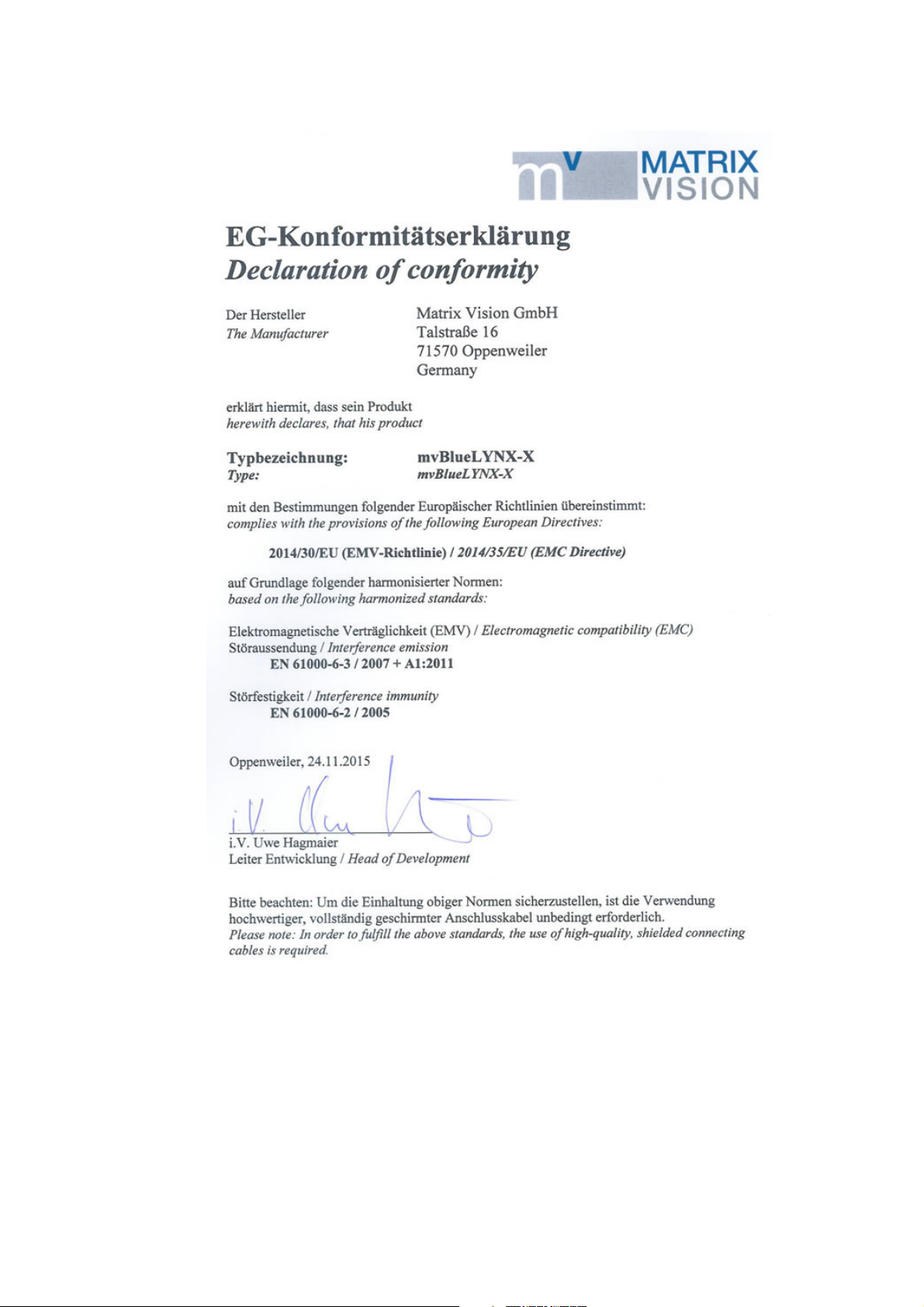
5.3 European Union Declaration of Conformity statement
The mvBlueLYNX-X is in conformity with all applicable essential requirements necessary for
CE marking. It corresponds to the EU EMC guideline 2014/30/EU based on the following
harmonized standards
Electromagnetic compatibility (EMC)
- Interference emmision EN 61000-6-3 / 2007
- Interference immunity EN 61000-6-2 / 2005
MATRIX VISION corresponds to the EU guideline WEEE 2002/96/EG on waste electrical and
electronic equipment and is registered under WEEE-Reg.-No. DE 25244305.
16 22 April 2016 Version - 1.49 MATRIX VISION GmbH
Page 27
mvBlueLYNX-X Technical Manual
MATRIX VISION GmbH 22 April 2016 Version - 1.49 17
Page 28

mvBlueLYNX-X Technical Manual
18 22 April 2016 Version - 1.49 MATRIX VISION GmbH
Page 29

6 About this Manual
6.1 Goal of the manual
This manual gives you an overview of the mvBlueLYNX-X, MATRIX VISION’s next generation smart
camera family, its technical data and basic operation of the mvBlueLYNX-X. Programming the device is
detailled in a separate documentation, which will be available in an online format.
6.2 Contents of the manual
At the beginning of the manual, you will get an introduction to the possible usages of the smart camera. The
further chapters contain general information about the mvBlueLYNX-X including:
technical data•
sensor data•
filters and lenses•
The general information is followed by the description of the
delivered default configuration and•
how to start with the mvBlueLYNX-X for the first time.•
Afterwards, it describes how to install and use software on the mvBlueLYNX-X followed by a general
description about the software developement kit. A troubleshooting chapter shows how to detect damages and
other inconveniences. Last but not least, a glossary explains abbreviations and technical terms.
MATRIX VISION GmbH 22 April 2016 Version - 1.49 19
Page 30

mvBlueLYNX-X Technical Manual
20 22 April 2016 Version - 1.49 MATRIX VISION GmbH
Page 31

7 Introduction
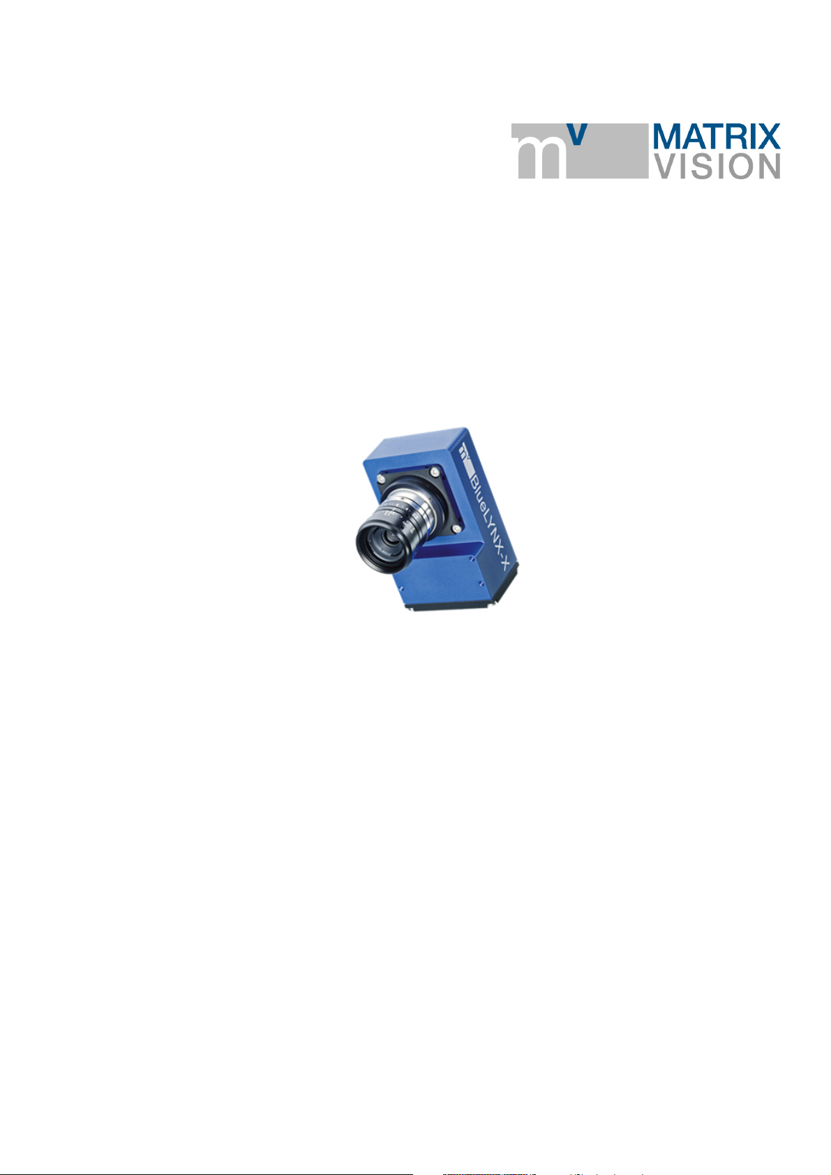
Figure 1: mvBlueLYNX-X
The mvBlueLYNX-X is the next generation intelligent (a.k.a. smart) camera product line. The CPU core from
Texas Instrument's DaVinci™ 37 series of digital media processors is based on
the state-of-the-art ARM Cortex-A8 technology with up to 1 GHz target clock and1.
image processing acceleration by an 800 MHz DSP coprocessor for parallel handling of multiple pixel
2.
and float data.
Using a modular approach, the mvBlueLYNX-X can be combined with the same image sensors as the
mvBlueCOUGAR family of cameras, creating an unprecedented flexible product spectrum.
The main aim of the system is to offer a freely programmable smart vision system with a standard OS. For
this reason, a Linux distribution called Ångström, which is available and maintained for a variety of
embedded devices is running on the mvBlueLYNX-X. A graphical user interface based on X window system
called Enlightenment is provided. By connecting a standard VESA display (e.g. 1024 x 768 resolution, 24 bit
color depths and 60 Hz), you can work with the mvBlueLYNX-X like any other PC with LINUX as operating
system.
The mvBlueLYNX-X is ideally suited for all classical areas of machine vision, the large processing power
and high-end display and graphics capability make it perfect for even higher end applications. The hardware
capabilities can be teamed with MATRIX VISION's machine vision library mvIMPACT or third party
libraries such as MVTec Halcon™, EVT EyeVision, or OpenCV.
mvBlueLYNX-X - Installing HALCON Embedded
Possible uses for the mvBlueLYNX-X include:
an image acquisition device,•
an image acquisition and processing device displaying results on a display,•
an image acquisition and processing device controlling a machine or system via PLC (e.g. a
•
packaging machine or sorter) or its own I/O,
a decentral intelligent image processing device in
•
single camera applications or♦
multiple camera applications.♦
By connecting a USB camera (e.g. mvBlueFOX-IGC), it is also possible to create a stereo vision system.
Like many other MATRIX VISION hardware with an Ethernet interface, the mvBlueLYNX-X is a GenICam
compliant smart camera, using SFNC for the names of the camera features. The mvBlueLYNX-X uses
MATRIX VISION GmbH 22 April 2016 Version - 1.49 21
Page 32
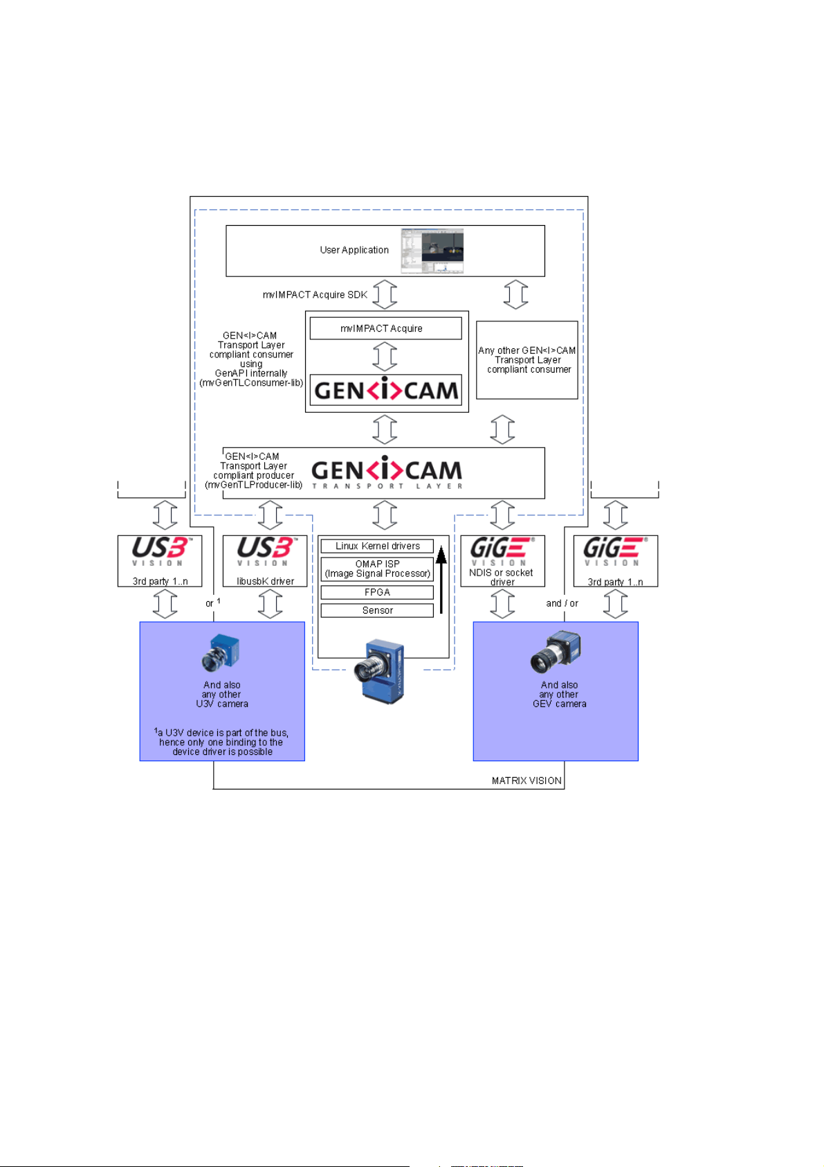
mvBlueLYNX-X Technical Manual
GenICam inside as a software API but does not have a Gigabit interface and does not use the GigE Vision®
protocol over its Fast Ethernet interface.
The following figure shows the software concept of the mvBlueLYNX-X and the other MATRIX VISION
camera devices:
Figure 2: Software concept of mvBlueLYNX-X
As shown in figure 2 the mvIMPACT Acquire interface is stacked on the GenICam layer. The mvIMPACT
Acquire interface internally uses the GenICam runtime libs, so that it can be considered as an user application
written with the GenICam interface.
7.1 Nomenclature
The mvBlueLYNX-X nomenclature scheme is as follows:
mvBlueLYNX-X(A)(B)(C)(D)-yyy-(1)(2)(3)(4)
- yyy: possible interface options
POE: Power over Ethernet, PoE class 2
22 22 April 2016 Version - 1.49 MATRIX VISION GmbH
Page 33

mvBlueLYNX-X Technical Manual
- (A): mvBlueLYNX version
1. Standard Version
- (B): Sensor type
0: CMOS
2: CCD
- (C): Sensor resolution
0a: 640 x 480, 1/3"
0b: 640 x 480, 1/2"
0d: 776 x 580, 1/2"
0w: 752 x 480, 1/3"
2 : 1280 x 964, 1/3"
2b: 1280 x 960, 1/3"
2d: 1280 x 960, 1/3"
2e: 1280 x 1024, 1/1.8"
3 : 1360 x 1024, 1/2"
4 : 1600 x 1200, 1/1.8"
5 : 2592 x 1944, 1/2.5"
5a: 2448 x 2050, 2/3"
- (D): Sensor color
G: Gray scale
C: Color
- (1): Lensholder
1 = C-Mount (standard = landscape)
2 = CS-Mount (landscape)
3 = C-Mount without back focus adjustment (landscape)
4 = CS-Mount without back focus adjustment (landscape)
5 = C-Mount (alternative = portrait)
6 = CS-Mount (portrait)
7 = C-Mount without back focus adjustment (portrait)
8 = CS-Mount without back focus adjustment (portrait)
The difference between (1) and (5), (2) and (6), (3) and (7) or (4) and (8) is the orientation of the
sensor.
Figure 3: mvBlueLYNX-X - "Landscape" orientation
Figure 4: mvBlueLYNX-X - "Portrait" orientation
MATRIX VISION GmbH 22 April 2016 Version - 1.49 23
Page 34

mvBlueLYNX-X Technical Manual
- (2): Filter
1 = IR-CUT (standard)
2 = glass
3 = daylight cut
9 = none
- (3): Case
1 = Color blue (standard)
2 = Color black, no logo
3 = Color blue, with XLMP
4 = Color black, with XLMP, no logo
9 = none
- (4): Other
1 = none (standard)
2 = I/O Extension
Samples
mvBlueLYNX-X120aG = CCD, 640x480 1/3", gray scale, C-mount landscape, IR-CUT filter, etc.1.
mvBlueLYNX-X105C-5211 = CMOS, 2448 x 2050, 2/3", color, C-mount portrait, glass filter, etc.2.
mvBlueLYNX-X122G-2192 = CCD, 1280 x 960, 1/3", gray scale, CS-mount landscape, IR-CUT
3.
filter filter, no case, I/O extension
-1111 is the standard delivery variant and for this reason it is not mentioned (see sample 1).
7.2 What's inside and accessories
Due to the varying fields of application the mvBlueLYNX-X is shipped with following accessories:
mvBlueLYNX-X (2 in figure 5)•
mvBlueLYNX-X SDK DVD with SDK and tool chain•
24 22 April 2016 Version - 1.49 MATRIX VISION GmbH
Page 35

mvBlueLYNX-X Technical Manual
Figure 5: mvBlueLYNX-X - recommended scope of the order
Additionally, to use the mvBlueLYNX-X you will need at least:
MV-DC1201 BLX IO (1 in figure 5, power supply with digital I/O on separate cable)•
KS-BLX-VGA-USB 01.0 (3 in figure 5, VGA and USB "Y" cable)•
a lens (by default, the mvBlueLYNX-X is shipped without lens)•
a mouse and a keyboard, if you require local input and control•
a VGA display if you require a local HMI (human machine interface)•
MATRIX VISION GmbH 22 April 2016 Version - 1.49 25
Page 36

mvBlueLYNX-X Technical Manual
Accessories for the mvBlueLYNX-X
Part code Description
MVBL-X I/O-BOX I/O-Box to connect and test a mvBlueLYNX-X camera, to loop the camera into an existing system, and to mix both connection variants selectively.
Manual:
http://www.matrix-vision.com/smart-vision-sensor-mvbluelynx-x.html?file=tl_files/mv11/support/Manuals/MV-X_IO-BOX_technical_manual_en.pdf
KS-BLX-IO6 02.0 I/O cable for additional I/Os.
KS-BLX-PWR Ready-made connection cable for power and I/O, length up to 20 m.
KS-BLX-VGA-USB
01.0
KS-BLX-VGA-USB
05.0
MICRO SD CARD
8GB
MV-DC1201 BLXIOPower supply 12V for mvBlueLYNX-X with digital I/O on separate cable, length: power 3 m, I/O: 0.5 m.
USB 2.0 cable and VGA cable for mvBlueLYNX-X, Hirose 12pin to USB2-A and VGA, length 1 m.
USB 2.0 cable and VGA cable for mvBlueLYNX-X, Hirose 12pin to USB2-A and VGA, length 5 m.
External MicroSD memory card with 8 GB.
26 22 April 2016 Version - 1.49 MATRIX VISION GmbH
Page 37

8 Technical Data
8.1 Dimensions of mvBlueLYNX-X
Figure 6: mvBlueLYNX-X dimensions and connectors
Length CMOSIS sensors Remaining sensors
Y 32 mm 30 mm
Lens protrusion C-Mount CS-Mount
X 8 mm (9.5 mm with max. Ø 20
mm)
C-Mount CS-Mount
W approx. 15 mm (C-mount) approx. 10 mm (CS-mount)
Z 17.526 mm (in air) 12.5 mm (in air)
6 mm
Figure 7: mvBlueLYNX-X dimensions and connectors order option -xx9x
MATRIX VISION GmbH 22 April 2016 Version - 1.49 27
Page 38

mvBlueLYNX-X Technical Manual
8.2 Specifications
Features mvBlueLYNX-X
CPU Texas Instruments (TI)
DM3730 (with DSP)
Core 1000 MHz ARM Cortex™-A8
Core
Coprocessor NEON™ SIMD Coprocessor
DSP 800 MHz TMS320C64x+™
DSP Core
Graphics Accelerator POWERVR SGX™ Graphics
Accelerator (OpenGL® ES 2.0)
@ 192 MHz
SDRAM 200 MHz
FLASH
RAM
Interfaces
Power consumption
internal µSD card, size 512 MBytes .. 8
GBytes
external second µSD card slot
DDR-RAM 512 MBytes
USB ports 1x Low power OTG - Micro
USB (100mA max.)
1x High power - Circular
connector (250mA max.)
VGA out Circular connector (max.
resolution WXGA)
Ethernet 100Mbit (Power over Ethernet
option available)
Digital inputs 2x opto-coupled 3..24V
Digital outputs 4x high-side solid state relay
10..24V
< 5W
Power supply
12...24VDC +- 10%
Ambient Temperature
Operation 0..50 C / 30 to 80% RH
Storage -20..60 C / 20 to 90% RH
Protection class IP30
Weight without lens approx. 195 g
28 22 April 2016 Version - 1.49 MATRIX VISION GmbH
Page 39

mvBlueLYNX-X Technical Manual
8.3 Camera interfaces
8.3.1 Circular connector male (Power / Digital I/O)
Figure 8: AlysiumTech 12-pin (male; top view), digital I/O, power
Pin. Signal Line in
wxPropView
1 GND (for VDC) grey/pink
2 + 12 - 24 VDC red 1
3 DigOut3 Line3 white pink 11
4 DigIn0 + Line4 brown grey 7
5 DigOut2 Line2 green yellow 10
6 DigOut0 Line0 yellow green 8
7 DigIn GND grey brown 6
8 RS232 RX pink white 3
9 RS232 TX blue black 4
10 HSD supply +24 VDC
(24 V supply for the
outputs)
11 DigIn1 + Line5 black orange 5
Digital I/O color
code of power
supply
"MV-DC1201
BLX IO REV2"
(bicoloured wire)
red light blue 12
Color code of cable
"KS-BLX-PWR"
blue 2
Pin. on the
mainboard
connection
header
12 DigOut1 Line1 purple violet 9
NC red/blue
(bicoloured wire)
Connector (camera side): AlysiumTech, type 61-W-30-1112 12 pins or equivalent•
Plug (matching cable plug): AlysiumTech, type 61-W-01-1112 12 pins or equivalent•
Plug (matching cable plug for mainboard connection header): Molex 0510211200•
8.3.1.1 Characteristics of the digital inputs
The digital inputs have inverse-polarity protection. If you are using negative voltage at the positive
input (e.g. sinusoidal signals), you do not have to connect a protective diode in series at the positive
input line.
High level +3 to +24 V
MATRIX VISION GmbH 22 April 2016 Version - 1.49 29
Page 40

Low level 0 to +0.3 V
mvBlueLYNX-X Technical Manual
Threshold (Low -->
High / High -->
Low)
I
max.
8.3.1.1.1 Delay
2.5 V ± 0.5 V
5mA
Figure 9: DigIn mvBlueLYNX-X
Figure 10: DigIn mvBlueLYNX-X Delay
Characteristics Symbol Test conditions Typ. Unit
Turn-On time t
Storage time t
Turn-Off time t
ON
S
OFF
R = 2 kOhm, Output voltage
5V, IF = 16mA
2 us
25
40
8.3.1.2 Characteristics of the digital outputs
High level +12.0 V to +24 V
I
out
4x 0.7 A max. short circuit
Low level max. +1 V
Each output has a short circuit protection between 1 A and 1.7 A (generally 1.3 A). So if you combine
two outputs with one load, the short circuit protection can have an effect.
30 22 April 2016 Version - 1.49 MATRIX VISION GmbH
Page 41

The high-side switches feature:
undervoltage detection•
current limitation•
overtemperature protection•
short circuit protection•
mvBlueLYNX-X Technical Manual
Figure 11: DigOut mvBlueLYNX-X
8.3.1.2.1 Delay
Figure 12: DigOut mvBlueLYNX-X Delay
Characteristics Symbol Typ. Unit
Turn-On time t
Rise time t
Fall time t
Turn-Off time t
8.3.1.2.2 Example circuit 1: High-side switch uses power supply of the camera
ON
R
F
OFF
20 us
10
8
30
In this case you have to bridge pin 2 (external power supply) with pin 10 (the supply of the outputs):
MATRIX VISION GmbH 22 April 2016 Version - 1.49 31
Page 42

mvBlueLYNX-X Technical Manual
Figure 13: Bridge circuit between Pin 2 and Pin 10
8.3.1.2.3 Example circuit 2: High-side switch uses external (higher) power supply
Following figure shows, how to connect, for example, high power flash LEDs in series at the direct drive
output at Pin 3:
Figure 14: LEDs connected in series to Pin 3 powered externally via Pin 10
A 24 V power supply is connected at Pin 10. To protect the LEDs a series resistor is needed, which can be
calculated in this way:
Voltage: UHS - (n * UF) = U
D
Series resistor: R = UD / 0.7 A
Power: P = dutycycle * UD * I
The duty cycle is a coefficient < 1, which defines the power of the resistor. It is the ratio of the time period
while current flows compared to the total time. If the current always flows, P = U * I will be the
determining factor. If the current only flows a hundredth of time (duty cycle 1%), a resistor with a hundredth
of power will be enough.
For the connected LEDs and the ground of the external power supply, you have to use the ground of the
camera at Pin 1.
The series resistor has to handle the power, which depends on the duty cycle and the frequency.
8.3.1.3 Using the serial port
The external serial port appears as a Linux standard device with the name /dev/ttyO0. It may be
programmed using usual Linux methods like the termios library. The port has no hardware handshake and
may be used with baudrates of up to at least 115200 baud.
The name of the serial port is /dev/ttyO0 (character O, digit 0).
8.3.2 Circular connector female (VGA / USB)
32 22 April 2016 Version - 1.49 MATRIX VISION GmbH
Page 43

mvBlueLYNX-X Technical Manual
Figure 15: AlysiumTech 12-pin (female; top view), VGA / USB
Pin. Signal Pin. on the
mainboard
connection
header
1 USB host D- 3
2 USB host D+ 4
3 USB host V+ 2
4 VGA HSync 7
5 VGA B 10
6 VGA R 11
7 VGA G 12
8 VGA VSync 8
9 GND 1
10 GND 9
11 I2C SDA 5
12 I2C SCL 6
Connector (camera side): AlysiumTech, type 61-W-31-1112 12 pins or equivalent•
Plug (matching cable plug): AlysiumTech, type 61-W-00-1112 12 pins or equivalent•
Plug (matching cable plug for mainboard connection header): Molex 0510211200•
The USB connector that is part of the "Y"-cable KS-BLX-VGA-USB 01.0 may be used to connect
USB 2.0 peripheral devices. At the moment it will not support USB 1.1 devices correctly. If you
connect a USB 1.1 device the USB port will turn off and you will need to restart the camera. To
connect both a mouse and keyboard at the same time it will be necessary to use a USB 2.0 hub.
The maximum VGA resolution depends on the pixel clock which cannot exceed 75MHz e.g. WXGA
1280 x 800 @ 60 Hz (=71MHz pixel clock) is possible.
MATRIX VISION GmbH 22 April 2016 Version - 1.49 33
Page 44

mvBlueLYNX-X Technical Manual
8.3.3 Circular connector female (Digital I/O; via add-on board BLX-IO)
With the order reference "BLX-IO", the mvBlueLYNX-X can be extended by additional digital inputs and
outputs.
Figure 16: AlysiumTech 6-pin (female; top view), Digital I/O
Pin. Signal
1 VCC_HSD
2 GND
3 IO_8
4 IO_7
5 IO_6
6 IO_5
Connector (camera side): AlysiumTech, type 61W-21-0106 6 pins or equivalent•
Plug (matching cable plug): AlysiumTech, type 61W-00-0106 6 pins or equivalent•
8.3.3.1 Characteristics when used as digital inputs
There are four inputs parallel with the outputs with both
TTL or•
PLC levels.•
This is switchable via software.
V
in
I
in
5V .. 24V (30V max. complete)
< 1mA
Propagation delay <= 1µs (+ optional 10µs debouncing logic / FPGA)
Switching threshold 2V @TTL / 10V @PLC
You can use the inputs to read the outputs.
34 22 April 2016 Version - 1.49 MATRIX VISION GmbH
Page 45

mvBlueLYNX-X Technical Manual
Figure 17: wxPropView - setting the addiitional digital I/Os
As shown in the figure, via LineMode you can set the mode of the I/O - either Output or Input. When
choosing Input, you can set the mv Input Threshold either to TTL or PLC.
8.3.3.2 Characteristics when used as digital outputs
The high-side switches has the same characteristics as the digital outputs of the circular connector male
(Power / Digital I/O). Additionally,
the outputs are protected against loss of ground,•
an external power supply is necessary (VCC_HSD signal) either via
•
pin 1 of this female connector or♦
pin 10 of the circular connector male (Power / Digital I/O) (which powers the output 1..4 as
♦
well but only up to 3A output load)
Figure 18: Setting of digital outputs
8.3.4 RJ45 network connector (Fast Ethernet / 100 Mbit)
With the -POE option, the camera is a class 2 compliant PoE device and pin 4,5 (V+) and 7,8 (V-) are
connected.
MATRIX VISION GmbH 22 April 2016 Version - 1.49 35
Page 46

mvBlueLYNX-X Technical Manual
Figure 19: RJ45, LAN
Pin. Signal I/O Comment Pin. on the mainboard connection
header
1 D1+ bi data positive
2 D1- bi data negative
3 D2+ bi data positive
4 NC - reserved for PoE
5 NC - reserved for PoE
6 D2- bi data negative
7 NC - reserved for PoE
8 NC - reserved for PoE
The pinout above corresponds to the standard TIA/EIA-568 for 100BASE-TX.
To use the Ethernet network connector please insert the appropriate cable.
A crossover cable is not needed. The camera supports autosensing of the cable polarity.
The camera has been set up to use a DHCP client to obtain an IP address. The camera has a unique MAC from
MATRIX VISION's assigned series. The Ethernet connector uses 100 Mbit/s FDX by default but should
auto-negotiate a lower rate or if needed.
8.3.5 USB-OTG (under the small metal plate)
The USB-OTG port is located under the small metal plate and is not restricted to USB 2.0 only. You can open
the metal cover with a 1.5 mm Allen key.
Using a USB "A" adapter, the OTG port will act like a host device. You can connect USB 2.0 or USB
•
1.1 peripherals like a mouse or keyboard or a memory stick. However, the maximum current
requirement of the connected device must not exceed 100 mA. You may connect a powered USB 2.0
hub to the OTG port to enable high-power devices such as hard disks to be used.
Using a USB "B" adapter or cable the OTG port will act like a peripheral device and may be used, for
•
example, for Ethernet-via-USB.
To use the mvBlueLYNX-X as a peripheral device as described in the second point, you will need a
configuration file usb-gagdet in /etc/default/.
The following content of this file ensures that the mvBlueLYNX-X will act like a
network adapter (RNDIS)•
serial interface (CDC ACM no further settings necessary) and•
36 22 April 2016 Version - 1.49 MATRIX VISION GmbH
Page 47

mvBlueLYNX-X Technical Manual
USB storage device•
when connected to a host PC:
USB_MODE="multi"
MODULE_OPTIONS="idVendor=0x164C idProduct=0x0203 iManufacturer=MATRIX-VISION iProduct=mvBlueLYNX-X file=/home/root/userdata.disk ro=0 removable=1"
The sample file /home/root/userdata.disk will be displayed as the USB storage resource. For
example, to create a FAT disc with 32 MB, the file should be like this:
cd
dd if=/dev/zero of=userdata.disk bs=1M count=32
sync
mkfs.vfat userdata.disk
If you want to have read/write access to userdata.disk on the mvBlueLYNX-X, you have to be
sure that the resource is not used on the host PC. Disconnect the mvBlueLYNX-X from the host PC and
mount the resource on the mvBlueLYNX-X locally:
cd
mkdir -p /media/disk
mount -n -t vfat -o loop userdata.disk /media/disk
The settings for the network adapter can be look like this in the /etc/network/interfaces files:
iface usb0 inet static
address 192.168.0.202
netmask 255.255.255.0
network 192.168.0.0
Now, the USB gadget will start while the system is booting. Manually, you can unload and start the additional
driver like this:
modprobe -r g_multi to unload it and1.
usb-gadget to start it.2.
At the host's side there is a difference between Linux and Windows system:
8.3.5.1 Linux
You will not have to install any drivers. After connecting, you have to configure the new network device
usb0:
sudo ifconfig usb0 up
sudo ifconfig usb0 192.168.0.203
The serial interface is available as /dev/ttyACM0.
The USB storage resource will be available as a normal USB stick.
8.3.5.2 Windows
Using Windows, you have to install the drivers of the serial interface and the network adapter after the initial
connecting of the mvBlueLYNX-X. In the device manager, the
CDC serial needs linux-cdc-acm.inf and•
RNDIS network adapter needs linux.inf.•
The USB storage does not need any driver installations.•
MATRIX VISION GmbH 22 April 2016 Version - 1.49 37
Page 48

mvBlueLYNX-X Technical Manual
Both inf files can be found on the DVD.
8.3.6 µSD card slot (under the small metal plate)
The µSD card port is also located under the small metal plate. You can open the metal cover with a 1.5 mm
Allen key.
The µSD card slot supports cards of up to 32 GB capacity.
You can easily damage the µSD card or the mechanics of the mvBlueLYNX-X by improper operation.
Please be careful when inserting, removing, or handling the µSD card. Keep the µSD card at right
angles to the backplate when inserting it into the slot!
8.3.7 Power LED
Color Description
1. Off No power or no bootloader found.
2. Red Bootloader was recognized and FPGA is booting-up. N.B. The LED remains turned off for
approx. 10 seconds after applying power.
3. Green Linux OS is running.
8.3.8 Status LEDs
The status LEDs can be used or set by the user. A standard Linux LED driver is used which can be controlled
by pseudo files in the /sys directory. I.e., the LEDs can be control by a script or by an application.
8.3.8.1 How to use the LEDs
For each LED there is a pseudo directory:
root@mvblx:~# ls -l /sys/devices/virtual/leds/
total 0
drwxr-xr-x 3 root root 0 Aug 5 16:20 mvblx:green:power
drwxr-xr-x 3 root root 0 Aug 5 16:20 mvblx:green:usr1
drwxr-xr-x 3 root root 0 Aug 5 16:20 mvblx:green:usr2
drwxr-xr-x 3 root root 0 Aug 5 16:20 mvblx:green:usr3
drwxr-xr-x 3 root root 0 Aug 5 16:20 mvblx:red:power
drwxr-xr-x 3 root root 0 Aug 5 16:20 mvblx:red:usr1
drwxr-xr-x 3 root root 0 Aug 5 16:20 mvblx:red:usr2
drwxr-xr-x 3 root root 0 Aug 5 16:20 mvblx:red:usr3
Under it, there is a pseudo file called brightness. In this folder you write either "0" (turn off) or another value
38 22 April 2016 Version - 1.49 MATRIX VISION GmbH
Page 49

mvBlueLYNX-X Technical Manual
> "0" (turn on). E.g.:
echo 1 > /sys/devices/virtual/leds/mvblx\:red\:usr1/brightness
or
echo 0 > /sys/devices/virtual/leds/mvblx\:red\:usr1/brightness
There is also a pseudo file called trigger:
root@mvblx:~# cat /sys/devices/virtual/leds/mvblx\:red\:usr1/trigger
[none] mmc0 mmc1 timer heartbeat backlight gpio default-on
You can write one of these key values after trigger. E.g.:
echo "heartbeat" > /sys/devices/virtual/leds/mvblx\:red\:usr1/trigger
The key values have the following meanings:
none: none•
mmc0 or mmc1: LED will flash if the internal (mmc0) or external (mmc1) SD card is accessed•
heartbeat: LED flashes regularly•
MATRIX VISION GmbH 22 April 2016 Version - 1.49 39
Page 50

mvBlueLYNX-X Technical Manual
40 22 April 2016 Version - 1.49 MATRIX VISION GmbH
Page 51

9 Sensor Data
9.1 Output sequence of color sensors (RGB Bayer)
Figure 20: Output sequence of RAW data
9.2 CCD
The ADC resolution of the CCD sensors is ≤ 14 bit; the image bit depth in memory is ≤ 12 bit.
9.2.1 Details of operation
The process of getting an image from the CCD sensor can be separated into three different phases:
Trigger1.
Exposure2.
Readout3.
Figure 21: CCD timing - TriggerOverlap
MATRIX VISION GmbH 22 April 2016 Version - 1.49 41
Page 52

mvBlueLYNX-X Technical Manual
In the Trigger Overlap ReadOut mode, the camera accepts a trigger signal the t
ealier than t
readout
is finished.
exposure
period
9.2.1.1 Trigger
When coming out of reset or ready with the last readout the CCD controller is waiting for a Trigger signal.
The following trigger modes are available:
Mode / Setting
Setting (GenICam) Description
(Device
Specific)
Continuous TriggerSelector =
Free running, no external trigger signal needed.
FrameStart
TriggerMode = Off
OnDemand TriggerSelector =
Image acquisition triggerd by command (software trigger).
FrameStart
TriggerMode = On
TriggerSource =
Software
ExposureMode =
Timed
To trigger one frame
execute the
TriggerSoftware
command then.
OnLowLevel TriggerSelector =
FrameStart
TriggerMode = On
TriggerSource =
TriggerActivation
= LevelLow
ExposureMode =
Timed
OnHighLevel TriggerSelector =
FrameStart
TriggerMode = On
TriggerSource =
TriggerActivation
= LevelHigh
ExposureMode =
Timed
OnFallingEdge TriggerSelector =
FrameStart
TriggerMode = On
TriggerSource =
TriggerActivation
= FallingEdge
ExposureMode =
Timed
As long as trigger signal is Low camera acquires images with
own timing.
As long as trigger signal is High camera acquires images with
own timing.
Each falling edge of trigger signal acquires one image.
OnRisingEdge Each rising edge of trigger signal acquires one image.
42 22 April 2016 Version - 1.49 MATRIX VISION GmbH
Page 53

mvBlueLYNX-X Technical Manual
TriggerSelector =
FrameStart
TriggerMode = On
TriggerSource =
TriggerActivation
= RisingEdge
ExposureMode =
Timed
OnHighExpose TriggerSelector =
FrameStart
TriggerMode = On
TriggerSource =
TriggerActivation
= LevelHigh
ExposureMode =
TriggerWidth
OnLowExpose TriggerSelector =
FrameStart
TriggerMode = On
TriggerSource =
TriggerActivation
= LowHigh
ExposureMode =
TriggerWidth
OnAnyEdge TriggerSelector =
FrameStart
TriggerMode = On
TriggerSource =
TriggerActivation
= AnyEdge
Each rising edge of trigger signal acquires one image, integration
time corresponds to pulse width.
Each falling edge of trigger signal acquires one image,
integration time corresponds to pulse width.
Start the exposure of a frame when the trigger input level
changes from high to low or from low to high.
9.2.1.2 Exposure
After an active trigger, the integration phase starts with a maximum jitter of t
. If flash illumination is
trig
enabled in software the flash output will be activated exactly while the sensor chip is integrating light.
Exposure time is adjustable by software in increments of treadline.
9.2.1.3 Readout
When integration is finished, the image is transferred to hidden storage cells on the CCD. Image data is then
shifted out line-by-line and transferred to memory. Shifting out non active lines takes tvshift, while shifting
out active lines will consume treadline. The number of active pixels per line will not have any impact on
readout speed.
MATRIX VISION GmbH 22 April 2016 Version - 1.49 43
Page 54

mvBlueLYNX-X Technical Manual
9.2.2 Models
9.2.2.1 mvBlueLYNX-X120a (VGA 640 x 480)
Feature Description
Manufacturer Sony
Sensor name ICX424AL/AQ
Max. frames
104
per second
Device
Interline CCD image sensor
Structure
Image size Diagonal 6mm (Type 1/3)
Number of
659 (H) x 494 (V) approx. 330K pixels
effective pixels
Total number
692 (H) x 504 (V) approx. 350K pixels
of pixels
Chip size 5.79mm (H) x 4.89mm (V)
Unit cell size 7.4µm (H) x 7.4µm (V)
Optical black
Horizontal (H) direction: Front 2 pixels, rear 31 pixels
Vertical (V) direction: Front 8 pixels, rear 2 pixels
Number of
Horizontal 16 Vertical 5
dummy bits
Substrate
Silicon
material
9.2.2.1.1 Spectral Sensitivity
9.2.2.1.1.1 Gray scale model
44 22 April 2016 Version - 1.49 MATRIX VISION GmbH
Page 55

9.2.2.1.1.2 Color model
mvBlueLYNX-X Technical Manual
Figure 22: Spectral sensitivity mvBlueLYNX-X120aG
Figure 23: Spectral sensitivity mvBlueLYNX-X120aC
9.2.2.1.2 Timings
Name Description Pixel clock
24.54 MHz 32 MHz 40 MHz
t
trig
Time from trigger (internal or
t
trig
= t
vshift
+ t
turn_on_delay_opto(tturn_on_delay_opto
external) to exposure start
t
wait
Time after a new trigger is
< 1us
accepted
t
trans
Image transfer time (move
7.99µs 6.13µs 4.90µs
image to readout cells in CCD)
t
readline
t
vshift
Time needed to readout a line 31.95µs 24.50µs 19.60µs
Time needed to shift unused
2.93µs 2.25µs 1.80µs
lines away
t
exposure
t
readout
Exposure time 10µs..10s 10µs..10s 10µs..10s
Image readout time (move
image from readout cells to
t
= ((ActiveLines + 1) * t
readout
t
) + t
vshift
trans
readline
memory
= approx. 2µs)
)) + ((504 - ActiveLines) *
In partial scan mode (readout window ysize < 480 lines).
To calculate the maximum frames per second (FPS
) you will need following formula (Expose mode: No
max
overlap):
FPS_max = 1
--------------------- t_readout + t_exposure
(Expose mode: Overlapped):
MATRIX VISION GmbH 22 April 2016 Version - 1.49 45
Page 56

mvBlueLYNX-X Technical Manual
t_readout < t_exposure: FPS_max = 1
-------------- t_exposure
t_readout > t_exposure: FPS_max = 1
-------------- t_readout
Example: Frame rate as function of lines & exposure time
Now, when we insert the values using exposure time of, for example, 8000 us, 480 lines and 40MHz pixel
clock (Expose mode: No overlap):
FPS_max = 1
--------------------------------------------------------------------- (((480 + 1) * 19.60 us) + ((504 - 480) * 1.80 us) + 4.90 us) + 8000 us
= 0.00005722231441372878 1 / us
= 57.2
46 22 April 2016 Version - 1.49 MATRIX VISION GmbH
Page 57

mvBlueLYNX-X Technical Manual
9.2.2.2 mvBlueLYNX-X120b (VGA 640 x 480)
Feature Description
Manufacturer Sony
Sensor name ICX414AL/AQ
Max. frames
104
per second
Device
Interline CCD image sensor with Had microlens
Structure
Image size Diagonal 6mm (Type 1/2)
Number of
659 (H) x 494 (V) approx. 330K pixels
effective pixels
Total number
692 (H) x 504 (V) approx. 350K pixels
of pixels
Chip size 7.48mm (H) x 6.15mm (V)
Unit cell size 9.9µm (H) x 9.9µm (V)
Optical black
Horizontal (H) direction: Front 2 pixels, rear 31 pixels
Vertical (V) direction: Front 8 pixels, rear 2 pixels
Number of
Horizontal 16 Vertical 5
dummy bits
Substrate
Silicon
material
9.2.2.2.1 Spectral Sensitivity
9.2.2.2.1.1 Gray scale model
MATRIX VISION GmbH 22 April 2016 Version - 1.49 47
Page 58
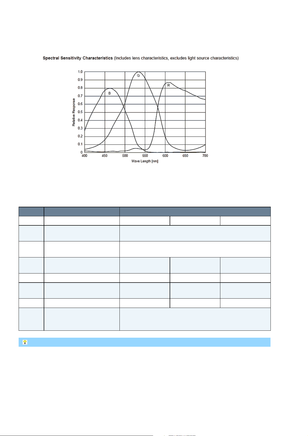
9.2.2.2.1.2 Color model
mvBlueLYNX-X Technical Manual
Figure 24: Spectral sensitivity mvBlueLYNX-X120bG
Figure 25: Spectral sensitivity mvBlueLYNX-X120bC
9.2.2.2.2 Timings
Name Description Pixel clock
24.54 MHz 32 MHz 40 MHz
t
trig
Time from trigger (internal or
t
trig
= t
vshift
+ t
turn_on_delay_opto(tturn_on_delay_opto
external) to exposure start
t
wait
Time after a new trigger is
< 1us
accepted
t
trans
Image transfer time (move
7.99µs 6.13µs 4.90µs
image to readout cells in CCD)
t
readline
t
vshift
Time needed to readout a line 31.95µs 24.50µs 19.60µs
Time needed to shift unused
2.93µs 2.25µs 1.80µs
lines away
t
exposure
t
readout
Exposure time 10µs..10s 10µs..10s 10µs..10s
Image readout time (move
image from readout cells to
t
= ((ActiveLines + 1) * t
readout
t
) + t
vshift
trans
readline
memory
= approx. 2µs)
)) + ((504 - ActiveLines) *
In partial scan mode (readout window ysize < 480 lines).
To calculate the maximum frames per second (FPS
) you will need following formula (Expose mode: No
max
overlap):
FPS_max = 1
--------------------- t_readout + t_exposure
(Expose mode: Overlapped):
48 22 April 2016 Version - 1.49 MATRIX VISION GmbH
Page 59

mvBlueLYNX-X Technical Manual
t_readout < t_exposure: FPS_max = 1
-------------- t_exposure
t_readout > t_exposure: FPS_max = 1
-------------- t_readout
Example: Frame rate as function of lines & exposure time
Now, when we insert the values using exposure time of, for example, 8000 us, 480 lines and 40MHz pixel
clock (Expose mode: No overlap):
FPS_max = 1
--------------------------------------------------------------------- (((480 + 1) * 19.60 us) + ((504 - 480) * 1.80 us) + 4.90 us) + 8000 us
= 0.00005722231441372878 1 / us
= 57.2
MATRIX VISION GmbH 22 April 2016 Version - 1.49 49
Page 60

mvBlueLYNX-X Technical Manual
9.2.2.3 mvBlueLYNX-X120d (SVGA 776 x 580)
Feature Description
Manufacturer Sony
Sensor name ICX415AL/AQ
Max. frames
87
per second
Device
Interline CCD image sensor with Had microlens
Structure
Image size Diagonal 6mm (Type 1/2)
Number of
782 (H) x 582 (V) approx. 460K pixels
effective pixels
Total number
823 (H) x 592 (V) approx. 490K pixels
of pixels
Chip size 7.48mm (H) x 6.15mm (V)
Unit cell size 8.3µm (H) x 8.3µm (V)
Optical black
Horizontal (H) direction: Front 3 pixels, rear 38 pixels
Vertical (V) direction: Front 8 pixels, rear 2 pixels
Number of
Horizontal 19 Vertical 5
dummy bits
Substrate
Silicon
material
9.2.2.3.1 Spectral Sensitivity
9.2.2.3.1.1 Gray scale model
50 22 April 2016 Version - 1.49 MATRIX VISION GmbH
Page 61

9.2.2.3.1.2 Color model
mvBlueLYNX-X Technical Manual
Figure 26: Spectral sensitivity mvBlueLYNX-X120dG
Figure 27: Spectral sensitivity mvBlueLYNX-X120dC
9.2.2.3.2 Timings
Name Description Pixel clock
29.5 MHz 48 MHz
t
trig
Time from trigger (internal or
external) to exposure start
t
= t
trig
t
turn_on_delay_opto(tturn_on_delay_opto
vshift
+
2µs)
t
wait
Time after a new trigger is
< 1us
accepted
t
trans
Image transfer time (move
30.51µs 18.75µs
image to readout cells in CCD)
t
readline
t
vshift
Time needed to readout a line 32µs 19.67µs
Time needed to shift unused
3.25µs 2µs
lines away
t
exposure
t
readout
Exposure time 10µs..10s 10µs..10s
Image readout time (move
image from readout cells to
t
= ((ActiveLines + 1) * t
readout
((592 - ActiveLines) * t
memory
vshift
= approx.
readline
) + t
trans
)) +
In partial scan mode (readout window ysize < 580 lines).
To calculate the maximum frames per second (FPS
) you will need following formula (Expose mode: No
max
overlap):
FPS_max = 1
--------------------- t_readout + t_exposure
(Expose mode: Overlapped):
MATRIX VISION GmbH 22 April 2016 Version - 1.49 51
Page 62

mvBlueLYNX-X Technical Manual
t_readout < t_exposure: FPS_max = 1
-------------- t_exposure
t_readout > t_exposure: FPS_max = 1
-------------- t_readout
Example: Frame rate as function of lines & exposure time
Now, when we insert the values using exposure time of, for example, 8000 us, 580 lines and 48MHz pixel
clock (Expose mode: No overlap):
FPS_max = 1
--------------------------------------------------------- (((580 + 1) * 19.67 us) + ((592 - 580) * 2 us) + 18.75 us)
= 0.00008717620577769021 1 / us
= 87.2
52 22 April 2016 Version - 1.49 MATRIX VISION GmbH
Page 63
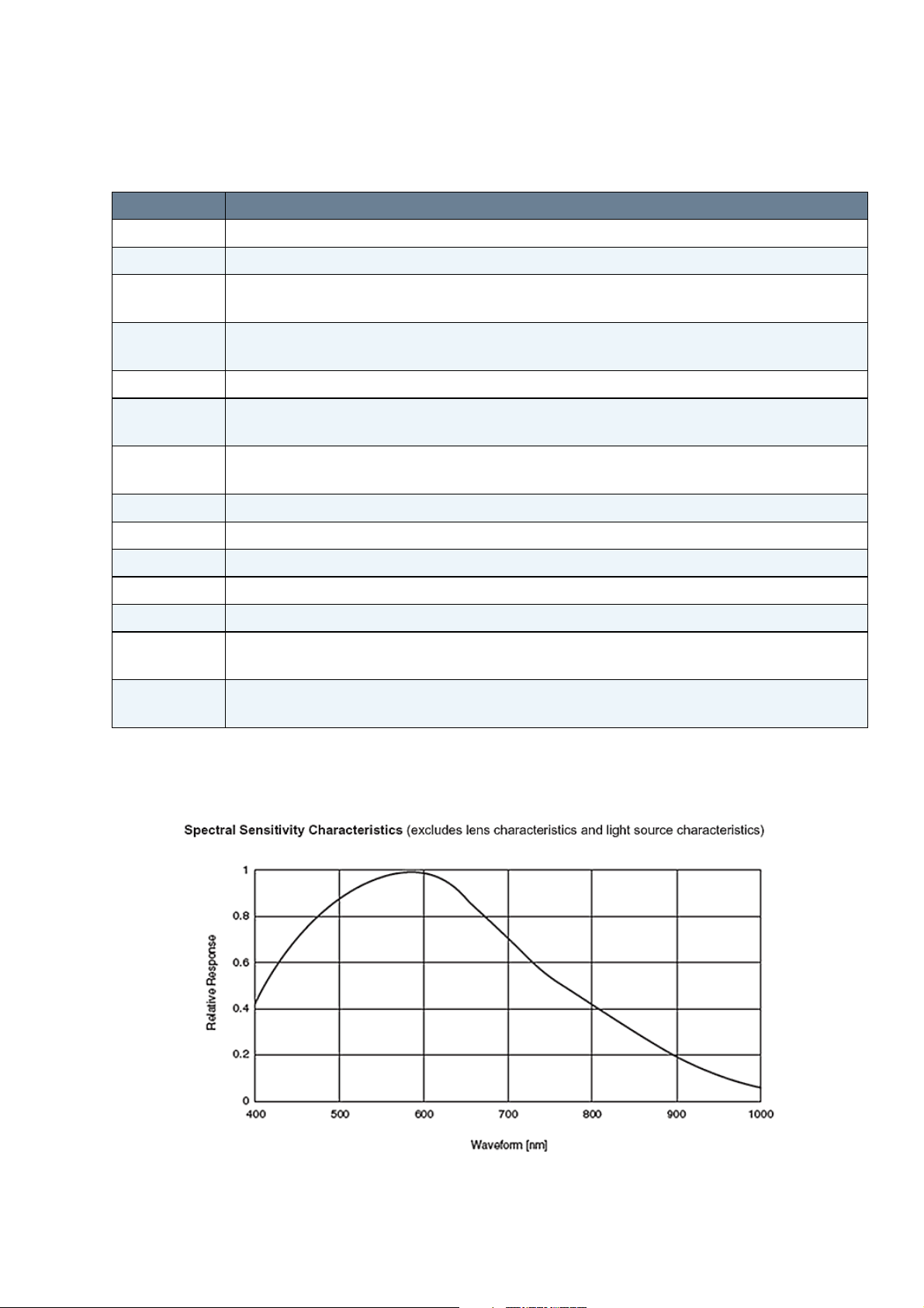
mvBlueLYNX-X Technical Manual
9.2.2.4 mvBlueLYNX-X122 (SXGA 1280 x 960)
Feature Description
Manufacturer Sony
Sensor name ICX445ALA/AQA
Max. frames
31
per second
Device
Interline CCD image sensor with ExViewHad microlens
Structure
Image size Diagonal 6mm (Type 1/3)
Number of
1296 (H) x 966 (V) approx. 1.25M pixels
effective pixels
Total number
1348 (H) x 976 (V) approx. 1.32M pixels
of pixels
Chip size 6.26mm (H) x 5.01mm (V)
Unit cell size 3.75µm (H) x 3.75µm (V)
Optical black
Horizontal (H) direction: Front 12 pixels, rear 40 pixels
Vertical (V) direction: Front 8 pixels, rear 2 pixels
Number of
Horizontal 4 Vertical 2
dummy bits
Substrate
Silicon
material
9.2.2.4.1 Spectral Sensitivity
9.2.2.4.1.1 Gray scale model
MATRIX VISION GmbH 22 April 2016 Version - 1.49 53
Page 64

9.2.2.4.1.2 Color model
mvBlueLYNX-X Technical Manual
Figure 28: Spectral sensitivity mvBlueLYNX-X122G
Figure 29: Spectral sensitivity mvBlueLYNX-X122C
9.2.2.4.2 Timings
Name Description Pixel clock
36 MHz 50 MHz
t
trig
Time from trigger (internal or
t
trig
= t
vshift
+ t
turn_on_delay_opto(tturn_on_delay_opto
external) to exposure start
t
wait
Time after a new trigger is
< 1us
accepted
t
trans
Image transfer time (move
16.25µs 11.70µs
image to readout cells in CCD)
t
readline
t
vshift
Time needed to readout a line 45.83µs 33.00µs
Time needed to shift unused
2.06µs 1.48µs
lines away
t
exposure
t
readout
Exposure time 10µs..10s 10µs..10s
Image readout time (move
image from readout cells to
t
= ((ActiveLines + 1) * t
readout
t
) + t
vshift
trans
readline
memory
= approx. 2µs)
)) + ((976 - ActiveLines) *
In partial scan mode (readout window ysize < 964 lines).
To calculate the maximum frames per second (FPS
) you will need following formula (Expose mode: No
max
overlap):
FPS_max = 1
--------------------- t_readout + t_exposure
(Expose mode: Overlapped):
54 22 April 2016 Version - 1.49 MATRIX VISION GmbH
Page 65

mvBlueLYNX-X Technical Manual
t_readout < t_exposure: FPS_max = 1
-------------- t_exposure
t_readout > t_exposure: FPS_max = 1
-------------- t_readout
Example: Frame rate as function of lines & exposure time
Now, when we insert the values using exposure time of, for example, 8000 us, 960 lines and 50MHz pixel
clock (Expose mode: No overlap):
FPS_max = 1
--------------------------------------------------------------------- (((960 + 1) * 33.00 us) + ((976 - 960) * 1.48 us) + 11.70 us) + 8000 us
= 0.00002515825802208794 1 / us
= 25.2
MATRIX VISION GmbH 22 April 2016 Version - 1.49 55
Page 66
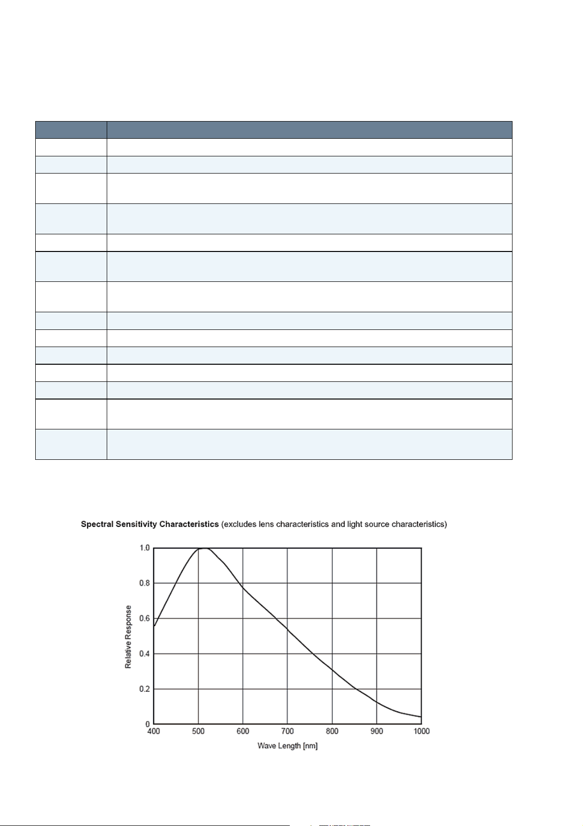
mvBlueLYNX-X Technical Manual
9.2.2.5 mvBlueLYNX-X123 (SXGA 1360 x 1024)
Feature Description
Manufacturer Sony
Sensor name ICX267AL/AK
Max. frames
30
per second
Device
Interline CCD image sensor
Structure
Image size Diagonal 8mm (Type 1/2)
Number of
1392 (H) x 1040 (V) approx. 1.45M pixels
effective pixels
Total number
1434 (H) x 1050 (V) approx. 1.5M pixels
of pixels
Chip size 7.6mm (H) x 4.65mm (V)
Unit cell size 4.65µm (H) x 4.65µm (V)
Optical black
Horizontal (H) direction: Front 2 pixels, rear 40 pixels
Vertical (V) direction: Front 8 pixels, rear 2 pixels
Number of
Horizontal 20 Vertical 3
dummy bits
Substrate
Silicon
material
9.2.2.5.1 Spectral Sensitivity
9.2.2.5.1.1 Gray scale model
56 22 April 2016 Version - 1.49 MATRIX VISION GmbH
Page 67

9.2.2.5.1.2 Color model
mvBlueLYNX-X Technical Manual
Figure 30: Spectral sensitivity mvBlueLYNX-X123G
Figure 31: Spectral sensitivity mvBlueLYNX-X123C
9.2.2.5.2 Timings
Name Description Pixel clock
28 MHz 56 MHz
t
trig
Time from trigger (internal or
t
trig
= t
vshift
+ t
turn_on_delay_opto(tturn_on_delay_opto
external) to exposure start
t
wait
Time after a new trigger is
< 1us
accepted
t
trans
Image transfer time (move
42.86µs 21.43µs
image to readout cells in CCD)
t
readline
t
vshift
Time needed to readout a line 63.93µs 31.96µs
Time needed to shift unused
8.57µs 4.29µs
lines away
t
exposure
t
readout
Exposure time 20µs..10s 20µs..10s
Image readout time (move
image from readout cells to
t
= ((ActiveLines + 1) * t
readout
t
) + t
vshift
trans
readline
memory
= approx. 2µs)
)) + ((1050 - ActiveLines) *
In partial scan mode (readout window ysize < 1024 lines).
To calculate the maximum frames per second (FPS
) you will need following formula (Expose mode: No
max
overlap):
FPS_max = 1
--------------------- t_readout + t_exposure
MATRIX VISION GmbH 22 April 2016 Version - 1.49 57
Page 68

mvBlueLYNX-X Technical Manual
(Expose mode: Overlapped):
t_readout < t_exposure: FPS_max = 1
-------------- t_exposure
t_readout > t_exposure: FPS_max = 1
-------------- t_readout
Example: Frame rate as function of lines & exposure time
Now, when we insert the values using exposure time of, for example, 8000 us, 1024 lines and 56MHz pixel
clock (Expose mode: No overlap):
FPS_max = 1
-------------------------------------------------------------------- (((1024 + 1) * 31.96 us) + ((1050 - 1024) * 4.29 us) + 8.57 us) + 8000 us
= 0.000024454678999324316 1 / us
= 24.5
58 22 April 2016 Version - 1.49 MATRIX VISION GmbH
Page 69

mvBlueLYNX-X Technical Manual
9.2.2.6 mvBlueLYNX-X124 (UXGA 1600 x 1200)
Feature Description
Manufacturer Sony
Sensor name ICX274AL/AQ
Max. frames
28
per second
Device
Interline CCD image sensor
Structure
Image size Diagonal 8.923mm (Type 1/1.8)
Number of
1600 (H) x 1200 (V) approx. 1.92M pixels
effective pixels
Total number
1688 (H) x 1248 (V) approx. 2.11M pixels
of pixels
Chip size 8.50mm (H) x 6.8mm (V)
Unit cell size 4.4µm (H) x 4.4µm (V)
Optical black
Horizontal (H) direction: Front 12 pixels, rear 48 pixels
Vertical (V) direction: Front 10 pixels, rear 2 pixels
Number of
Horizontal 28 Vertical 1
dummy bits
Substrate
Silicon
material
9.2.2.6.1 Spectral Sensitivity
9.2.2.6.1.1 Gray scale model
MATRIX VISION GmbH 22 April 2016 Version - 1.49 59
Page 70

9.2.2.6.1.2 Color model
mvBlueLYNX-X Technical Manual
Figure 32: Spectral sensitivity mvBlueLYNX-X124G
Figure 33: Spectral sensitivity mvBlueLYNX-X124C
9.2.2.6.2 Timings
Name Description Pixel clock
36 MHz 56 MHz 65 MHz
t
trig
Time from trigger (internal or
t
trig
= t
vshift
+ t
turn_on_delay_opto(tturn_on_delay_opto
external) to exposure start
t
wait
Time after a new trigger is
< 1us
accepted
t
trans
Image transfer time (move
35.56µs 22.86µs 19.69µs
image to readout cells in CCD)
t
readline
t
vshift
Time needed to readout a line 53.33µs 34.29µs 29.54µs
Time needed to shift unused
5.56µs 3.57µs 3.08µs
lines away
t
exposure
t
readout
Exposure time 20µs..10s 20µs..10s 20µs..10s
Image readout time (move
image from readout cells to
t
= ((ActiveLines + 1) * t
readout
t
) + t
vshift
trans
readline
memory
= approx. 2µs)
)) + ((1248 - ActiveLines) *
In partial scan mode (readout window ysize < 1200 lines).
To calculate the maximum frames per second (FPS
) you will need following formula (Expose mode: No
max
overlap):
FPS_max = 1
--------------------- t_readout + t_exposure
60 22 April 2016 Version - 1.49 MATRIX VISION GmbH
Page 71

mvBlueLYNX-X Technical Manual
(Expose mode: Overlapped):
t_readout < t_exposure: FPS_max = 1
-------------- t_exposure
t_readout > t_exposure: FPS_max = 1
-------------- t_readout
Example: Frame rate as function of lines & exposure time
Now, when we insert the values using exposure time of, for example, 8000 us, 1024 lines and 56MHz pixel
clock (Expose mode: No overlap):
FPS_max = 1
--------------------------------------------------------------------- (((1200 + 1) * 29.54 us) + ((1248 - 1200) * 3.08 us) + 19.69 us) + 8000 us
= 0.0000229120952263 1 / us
= 22.9
MATRIX VISION GmbH 22 April 2016 Version - 1.49 61
Page 72

mvBlueLYNX-X Technical Manual
9.2.2.7 mvBlueLYNX-X125a (5 Mpix 2448 x 2050)
Feature Description
Manufacturer Sony
Sensor name ICX655ALA/AQA
Max. frames
10
per second
Device
Interline CCD image sensor with SuperHad microlens
Structure
Image size Diagonal 11.016mm (Type 2/3)
Number of
2456 (H) x 2058 (V) approx. 5.05M pixels
effective pixels
Total number
2536 (H) x 2068 (V) approx. 5.24M pixels
of pixels
Chip size 9.93mm (H) x 8.70mm (V)
Unit cell size 3.45µm (H) x 3.45µm (V)
Optical black
Horizontal (H) direction: Front 40 pixels, rear 40 pixels
Vertical (V) direction: Front 8 pixels, rear 2 pixels
Number of
Horizontal 1 per channel Vertical 1
dummy bits
Substrate
Silicon
material
9.2.2.7.1 Spectral Sensitivity
9.2.2.7.1.1 Gray scale model
Figure 34: Spectral sensitivity mvBlueLYNX-X125aG
62 22 April 2016 Version - 1.49 MATRIX VISION GmbH
Page 73

9.2.2.7.1.2 Color model
mvBlueLYNX-X Technical Manual
Figure 35: Spectral sensitivity mvBlueLYNX-X125aC
9.2.2.7.2 Timings
Name Description Pixel clock
60 MHz 66 MHz
t
trig
Time from trigger (internal or
external) to exposure start
t
= t
trig
t
turn_on_delay_opto(tturn_on_delay_opto
vshift
+
2µs)
t
wait
Time after a new trigger is
< 1us
accepted
t
trans
Image transfer time (move
30.87µs 28.06µs
image to readout cells in CCD)
t
readline
t
vshift
Time needed to readout a line 53.20µs 48.36µs
Time needed to shift unused
10.00µs 9.09µs
lines away
t
exposure
t
readout
Exposure time 20µs..10s 20µs..10s
Image readout time (move
image from readout cells to
t
= ((ActiveLines + 1) * t
readout
((2068 - ActiveLines) * t
memory
vshift
= approx.
readline
) + t
trans
)) +
In partial scan mode (readout window ysize < 2050 lines).
To calculate the maximum frames per second (FPS
) you will need following formula (Expose mode: No
max
overlap):
FPS_max = 1
--------------------- t_readout + t_exposure
MATRIX VISION GmbH 22 April 2016 Version - 1.49 63
Page 74

mvBlueLYNX-X Technical Manual
(Expose mode: Overlapped):
t_readout < t_exposure: FPS_max = 1
-------------- t_exposure
t_readout > t_exposure: FPS_max = 1
-------------- t_readout
Example: Frame rate as function of lines & exposure time
Now, when we insert the values using exposure time of, for example, 8000 us, 1024 lines and 56MHz pixel
clock (Expose mode: No overlap):
FPS_max = 1
-------------------------------------------------------------------------- (((2050 + 1) * 53.20 us) + ((2068 - 2050) * 10.00 us) + 30.87 us) + 8000 us
= 0.00000852340018549 1 / us
= 8.5
64 22 April 2016 Version - 1.49 MATRIX VISION GmbH
Page 75

mvBlueLYNX-X Technical Manual
9.3 CMOS
9.3.1 Details of operation
The CMOS sensors offer two different modes of operation:
Free running mode (Overlapping integration and readout)1.
Snapshot mode (Sequential integration and readout)2.
9.3.1.1 Free running mode
In free running mode, the sensor reaches its maximum frame rate. This is done by overlapping erase,
integration and readout phase. The sensor timing in free running mode is fixed, so there is no control when to
start an acquisition. This mode is used with trigger mode Continuous.
9.3.1.2 Snapshot mode
In snapshot mode, the image acquisition process consists off several sequential phases:
Trigger1.
Erase, exposure and readout2.
9.3.1.2.1 Trigger
Snapshot mode starts with a trigger. This can be either a hardware or a software signal.
The CMOS sensors used in mvBlueLYNX-X cameras support the following trigger modes:
Mode / Setting
(Device
Specific)
Continuous TriggerSelector =
OnDemand TriggerSelector =
Setting (GenICam) Description
Free running, no external trigger signal needed.
FrameStart
TriggerMode = Off
Image acquisition triggerd by command (software trigger).
FrameStart
TriggerMode = On
TriggerSource =
Software
ExposureMode =
Timed
To trigger one frame
execute the
TriggerSoftware
command then.
OnLowLevel TriggerSelector =
FrameStart
TriggerMode = On
MATRIX VISION GmbH 22 April 2016 Version - 1.49 65
As long as trigger signal is Low camera acquires images with
own timing.
Page 76

mvBlueLYNX-X Technical Manual
TriggerSource =
TriggerActivation
= LevelLow
ExposureMode =
Timed
OnHighLevel TriggerSelector =
FrameStart
TriggerMode = On
TriggerSource =
TriggerActivation
= LevelHigh
ExposureMode =
Timed
OnHighExpose TriggerSelector =
FrameStart
TriggerMode = On
TriggerSource =
TriggerActivation
= LevelHigh
ExposureMode =
TriggerWidth
If an external trigger signal occurs (e.g. high or low), the sensor will start to expose and readout one image.
Now, if the trigger signal is still available, the sensor will start to expose and readout the next image (see
figure 36, upper part). This will lead to an acquisition just like using continuous trigger.
As long as trigger signal is High camera acquires images with
own timing.
Each rising edge of trigger signal acquires one image, integration
time corresponds to pulse width. (only with -X105)
Figure 36: External Trigger with CMOS sensors
If you want to avoid this effect, you have to adjust the trigger signal. As you can see in figure 36 (lower part),
the possible period is small.
66 22 April 2016 Version - 1.49 MATRIX VISION GmbH
Page 77

mvBlueLYNX-X Technical Manual
9.3.1.2.1.1 Example
External synchronized image acquisition (high active)
Trigger modes
•
OnHighLevel:
♦
The high level of the trigger has to be shorter than the frame time. In this case, the sensor will
make one image exactly. If the high time is longer, there will be images with the possible
frequency of the sensor as long as the high level takes. The first image will start with the
low-high edge of the signal. The integration time of the exposure register will be used.
OnLowLevel:
♦
The first image will start with the high-low edge of the signal.
OnHighExpose
♦
This mode is like OnHighLevel, however, the exposure time is used like the high time of
the signal.
9.3.1.2.2 Erase, exposure and readout
All pixels are light sensitive at the same period of time. The whole pixel core is reset simultaneously and after
the exposure time all pixel values are sampled together on the storage node inside each pixel. The pixel core is
read out line-by-line after integration.
Exposure and read out cycle is carry-out in serial; that causes that no integration is possible during read
out. The step width for the exposure time is 1 µs. Image data is then shifted out line-by-line and
transferred to memory.
MATRIX VISION GmbH 22 April 2016 Version - 1.49 67
Page 78
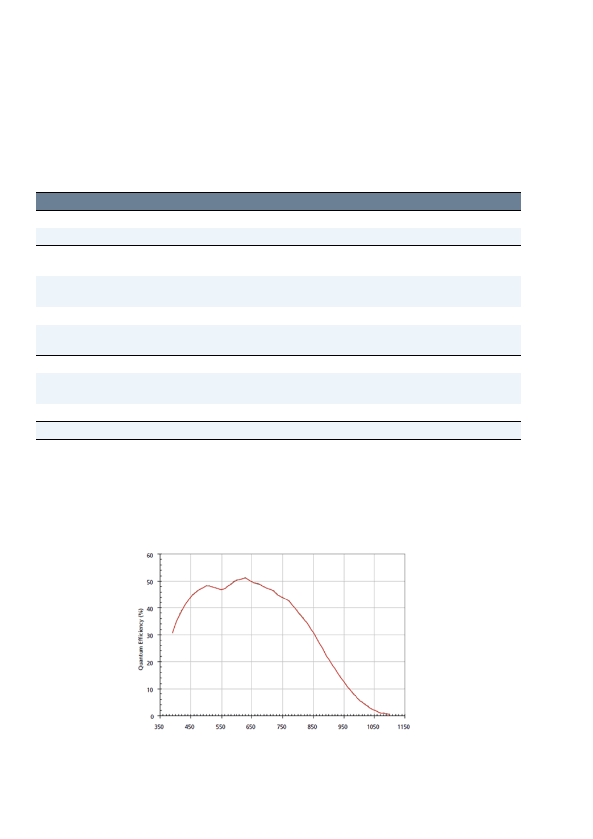
mvBlueLYNX-X Technical Manual
9.3.2 Models
9.3.2.1 mvBlueLYNX-X100w (WVGA 752 x 480)
The sensor uses a full frame shutter (ShutterMode = FrameShutter), i.e. all pixels are reset at the same
time and the exposure commences. It ends with the charge transfer of the voltage sampling.
Feature Description
Manufacturer Aptina
Sensor name MT9V034
Max. frames
117
per second
Device
CMOS image sensor with HDR
Structure
SNR
DNR (normal /
55 dB / > 110 dB
HDR)
Image size Type 1/3
Number of
752 (H) x 480 (V)
effective pixels
Chip size 4.51 (H) x 2.88mm (V)
Unit cell size 6µm (H) x 6µm (V)
ADC
10 bit → 12, 10, 8 bit
resolution /
output
9.3.2.1.1 Spectral Sensitivity
9.3.2.1.1.1 Gray scale model
Figure 37: mvBlueLYNX-X100wG
68 22 April 2016 Version - 1.49 MATRIX VISION GmbH
Page 79
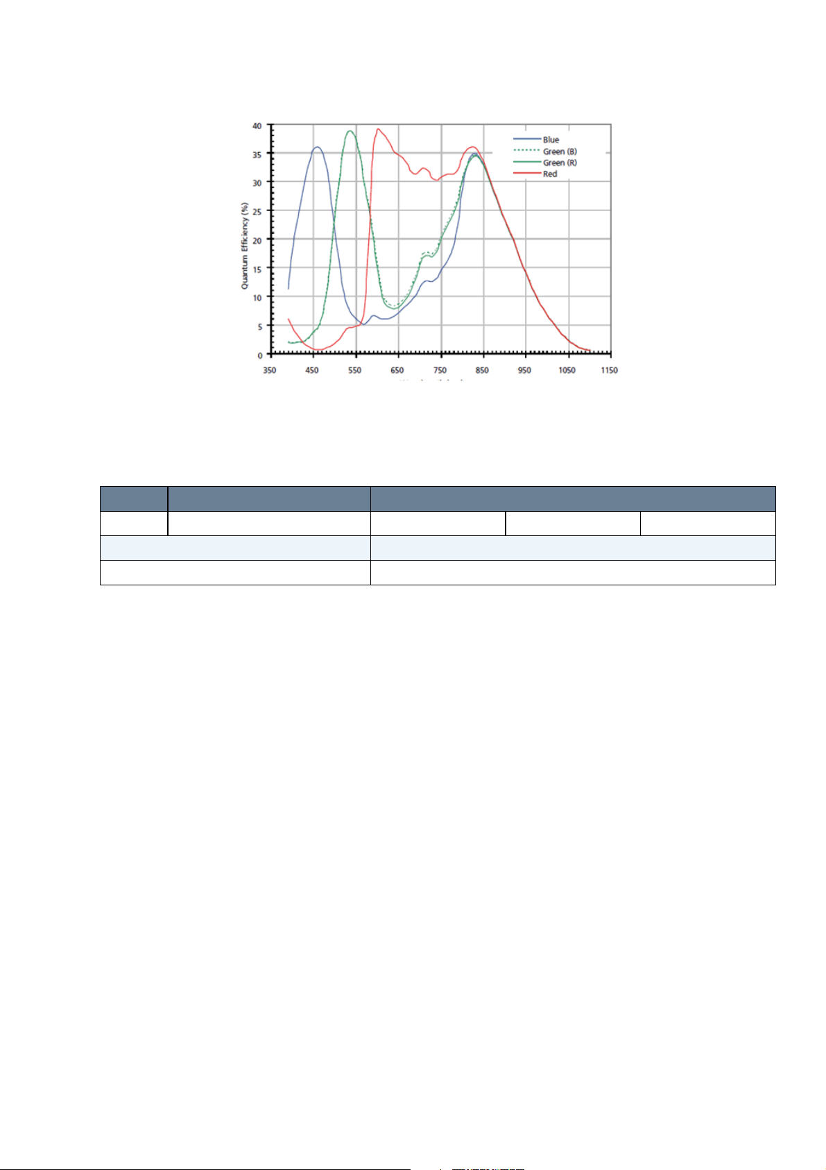
9.3.2.1.1.2 Color model
9.3.2.1.2 Timings
mvBlueLYNX-X Technical Manual
Figure 38: mvBlueLYNX-X100wC
Name Description Pixel clock
27 MHz 40 MHz 50 MHz
Horizontal blank 61
Vertical blank 45
9.3.2.1.2.1 Free running mode
To calculate the maximum frames per second (FPS
FrameTime = (ImageWidth + HorizonalBlank) * ((ImageHeight + VerticalBlank) / PixelClock)
) in free running mode you will need following formula:
max
If exposure time is lower than frame time:
FPS_max = 1
--------------------- FrameTime / 1000000
If exposure time is greater than frame time:
FPS_max = 1
--------------------- ExposureTime / 1000000
9.3.2.1.2.2 Snapshot mode
To calculate the maximum frames per second (FPS
FrameTime = (ImageWidth + HorizonalBlank) * ((ImageHeight + VerticalBlank) / PixelClock)
) in snapshot mode you will need following formula:
max
If exposure time is lower than frame time:
FPS_max = 1
---------------------------------- FrameTime + ExposureTime / 1000000
MATRIX VISION GmbH 22 April 2016 Version - 1.49 69
Page 80

mvBlueLYNX-X Technical Manual
9.3.2.2 mvBlueLYNX-X102b (SXGA 1280 x 960)
The sensor uses a pipelined global snapshot shutter, i.e. light exposure takes place on all pixels in parallel,
although subsequent readout is sequential.
Feature Description
Manufacturer Aptina
Sensor name MT9M021
Max. frames
40.6
per second
Device
CMOS image sensor
Structure
SNR 40 dB
DNR (normal /
> 61 dB /
HDR)
Image size Type 1/3
Number of
1280 (H) x 960 (V)
effective pixels
Unit cell size 3.75µm (H) x 3.75µm (V)
ADC
12 bit → 12, 10, 8 bit
resolution /
output
9.3.2.2.1 Spectral Sensitivity
9.3.2.2.1.1 Gray scale model
Figure 39: mvBlueLYNX-X102bG
70 22 April 2016 Version - 1.49 MATRIX VISION GmbH
Page 81

9.3.2.2.1.2 Color model
mvBlueLYNX-X Technical Manual
Figure 40: mvBlueLYNX-X102bC
9.3.2.2.2 Timings
Name Description Pixel clock
40 MHz 66 MHz
Line 1650
Vertical blank 25
9.3.2.2.2.1 Free running mode
To calculate the maximum frames per second (FPS
FrameTime = (ImageHeight * (Line / PixelClock)) + (VerticalBlank * (Line / PixelClock))
) in free running mode you will need following formula:
max
If exposure time is lower than frame time:
FPS_max = 1
--------------------- FrameTime / 1000000
If exposure time is greater than frame time:
FPS_max = 1
--------------------- ExposureTime / 1000000
9.3.2.2.2.2 Snapshot mode
To calculate the maximum frames per second (FPS
FrameTime = (ImageHeight * (Line / PixelClock)) + (VerticalBlank * (Line / PixelClock))
) in snapshot mode you will need following formula:
max
If exposure time is lower than frame time:
FPS_max = 1
MATRIX VISION GmbH 22 April 2016 Version - 1.49 71
Page 82

mvBlueLYNX-X Technical Manual
---------------------------------- FrameTime + ExposureTime / 1000000
72 22 April 2016 Version - 1.49 MATRIX VISION GmbH
Page 83

mvBlueLYNX-X Technical Manual
9.3.2.3 mvBlueLYNX-X102e (SXGA 1280 x 1024)
The sensor uses a full frame shutter (ShutterMode = FrameShutter), i.e. all pixels are reset at the same
time and the exposure commences. It ends with the charge transfer of the voltage sampling.
Feature Description
Manufacturer E2V
Sensor name EV76C560
Max. frames
60
per second
Device
CMOS image sensor
Structure
SNR 41 dB
DNR (normal /
62 dB /
HDR)
Image size Type 1/1.8
Number of
1280 (H) x 1024 (V)
effective pixels
Unit cell size 5.3µm (H) x 5.3µm (V)
ADC
10 bit (10-8 companding) → 10, 8 bit
resolution /
output
9.3.2.3.1 Spectral Sensitivity
9.3.2.3.1.1 Spectral response and quantum efficiency
Figure 43: mvBlueLYNX-X102e
MATRIX VISION GmbH 22 April 2016 Version - 1.49 73
Page 84

9.3.2.3.2 Timings
Name Value
InternalLineLength 944
InternalADCClock 118.75
9.3.2.3.2.1 Free running mode
mvBlueLYNX-X Technical Manual
To calculate the maximum frames per second (FPS
ReadOutTime = RowTime * (ImageHeight + 10) / 1000
) in free running mode you will need following formula:
max
If exposure time is lower than frame time:
1000
FPS_max = ------------ ReadOutTime
If exposure time is greater than frame time:
1
FPS_max = ------------- ExposureTime
9.3.2.3.2.2 Snapshot mode
To calculate the maximum frames per second (FPS
ReadOutTime = RowTime * (ImageHeight + 10) / 1000
) in snapshot mode you will need following formula:
max
If exposure time is lower than frame time:
1000
FPS_max = --------------------------- ReadOutTime + ExposureTime
9.3.2.3.2.3 Linescan mode
The sensor offers also a usage as a line scan sensor. One (gray scale sensor) or two lines (in terms of color
sensor) can be selected to be read out of the full line height of 1024 lines. This or these lines are grouped to a
pseudo frame of selectable height in the internal buffer of the camera.
The camera then outputs these frames which contain multiples of the same scan line(s) without gaps or
interruptions.
To operate in line scan mode, use the following properties:
In Setting -> Base -> Camera -> GenICam -> Device Control, please change the Device Scan Type
1.
to Linescan.
In Setting -> Base -> Camera -> GenICam -> Image Format Control, please set Width and Height.
2.
Height specifies how often the same line(s) will be used to reach the height of the image.
Use Offset X to shift horizontally the starting point of the exposed line.
Use Offset Y to shift the scan line vertically (typically to 512 which represents the optical center).
The sensor will not get faster by windowing in x direction.
74 22 April 2016 Version - 1.49 MATRIX VISION GmbH
Page 85

mvBlueLYNX-X Technical Manual
Finally, in Setting -> Base -> Camera -> GenICam -> Acquisition Control, please adapt the
3.
Exposure Time.
For high linescan rates the exposure time has to be proportionally low. To achieve the maximum
linescan rate of 12.6 kHz (gray scale sensor) the exposure time has to be set to approx. 60 us.
You may use longer exposure times at the expense of scanning frequency.
You can use either Continuous or a trigger mode as Acquisition Mode in Setting -> Base -> Camera ->
GenICam -> Acquisition Control. However, if an external (line) trigger will have to be used, it is
absolutely required that the external trigger is always present. During a trigger interruption, controlling
or communication to the camera is not possible!
MATRIX VISION GmbH 22 April 2016 Version - 1.49 75
Page 86

mvBlueLYNX-X Technical Manual
9.3.2.4 mvBlueLYNX-X105 (5MP 2592 x 1944)
This sensor uses two acquisition modes:
rolling shutter (ShutterMode = ElectronicRollingShutter) and•
global reset release shutter (ShutterMode = GlobalResetRelease).•
With the rolling shutter the lines are exposed for the same duration, but at a slightly different point in time:
Figure 44: CMOS sensor -X105 - rolling shutter
Moving objects together with a rolling shutter can cause a shear in moving objects.
The global reset release shutter, which is only available in triggered operation, starts the exposure of all rows
simultaneously and the reset to each row is released simultaneously, too. However, the readout of the lines is
equal to the readout of the rolling shutter: line by line:
Figure 45: CMOS sensor -X105 - global reset release shutter
This means, the bottom lines of the sensor will be exposured longer! For this reason, this mode will
only make sense, if there is no extraneous light and the flash duration is shorter or equal to the exposure
time.
Global reset release will only make sense, if a flash is used which is brighter than the ambient light. The
settings in wxPropView will look like this:
76 22 April 2016 Version - 1.49 MATRIX VISION GmbH
Page 87

mvBlueLYNX-X Technical Manual
Figure 46: CMOS sensor -X105 - global reset release dig I/O settings
In this case, DigOut0 gets a high signal as long as the exposure time (which is synchronized with the
GlobalResetRelease). This signal can start a flash light.
Feature Description
Manufacturer Aptina
Sensor name MT9P031
Max. frames
11.7
per second
Device
CMOS image sensor
Structure
SNR > 38 dB
DNR (normal /
> 70 dB /
HDR)
Image size Type 1/2.5
Number of
2592 (H) x 1944 (V)
effective pixels
Chip size 5.70 (H) x 4.28mm (V)
Unit cell size 2.2µm (H) x 2.2µm (V)
ADC
10 bit → 12, 10, 8 bit
resolution /
output
9.3.2.4.1 Spectral Sensitivity
9.3.2.4.1.1 Gray scale model
Figure 47: Spectral sensitivity mvBlueLYNX-X105G
9.3.2.4.1.2 Color model
MATRIX VISION GmbH 22 April 2016 Version - 1.49 77
Page 88

9.3.2.4.2 Timings
mvBlueLYNX-X Technical Manual
Figure 48: Spectral sensitivity mvBlueLYNX-X105C
Name Description Pixel clock
40 MHz 80 MHz
Vertical
9
blank
Line 1900
9.3.2.4.2.1 Free running mode
To calculate the maximum frames per second (FPS
FrameTime = (ImageHeight * (Line / PixelClock)) + (VerticalBlank * (Line / PixelClock))
) in free running mode you will need following formula:
max
If exposure time is lower than frame time:
FPS_max = 1
--------------------- FrameTime / 1000000
If exposure time is greater than frame time:
FPS_max = 1
--------------------- ExposureTime / 1000000
9.3.2.4.2.2 Snapshot mode
To calculate the maximum frames per second (FPS
FrameTime = (ImageHeight * (Line / PixelClock)) + (VerticalBlank * (Line / PixelClock))
) in snapshot mode you will need following formula:
max
If exposure time is lower than frame time:
FPS_max = 1
---------------------------------- FrameTime + ExposureTime / 1000000
78 22 April 2016 Version - 1.49 MATRIX VISION GmbH
Page 89

10 Filter and Lenses
10.1 Filters
MATRIX VISION offers three filters for the mvBlueLYNX-X camera. The hot mirror filter is part of the
standard delivery condition.
10.1.1 Hot mirror filter
The hot mirror filter FILTER IR-CUT 20X1 FE has great transmission in the visible spectrum and blocks out
a significant portion of the IR energy.
10.1.1.1 Technical data
Diameter 20.0 mm
Thickness 1.0 mm
Material Borofloat
Characteristics T = 50% @ 650 ± 10 nm
T > 92% 390-620 nm
R
> 95% 700-1150 nm
avg
AOI = 0 degrees
ground with protection chamfer
Surface quality Polished on both sides P4
Surface
irregularity
5/3x0.06 on both sides
Figure 49: IR-CUT 20X1 FE wavelengths and transmission diagram
10.1.2 Glass filter
It is also possible to choose the glass filter Glass-20x1 with following characteristics:
10.1.2.1 Technical data
Glass thickness 1.0 mm
MATRIX VISION GmbH 22 April 2016 Version - 1.49 79
Page 90

mvBlueLYNX-X Technical Manual
Material Borofloat without coating
ground with protection chamfer
Surface quality polished on both sides P4
Surface
irregularity
5/3x0.06 on both sides
10.2 Lenses
MATRIX VISION offers a high-quality selection of lenses. If you have questions about our accessories,
please contact our sales team: info@matrix-vision.com.
80 22 April 2016 Version - 1.49 MATRIX VISION GmbH
Page 91

11 Initial Delivery Configuration
11.1 Booting
By default, the mvBlueLYNX-X boots
from the external µSD card slot,1.
then from the internal one.2.
It is not possible to boot from USB instead of µSD card.
11.2 Linux OS environment
The mvBlueLYNX-X has an internal FLASH memory (SD card, single level 1) with two partitions:
LINUX (886.4 MB, 54% allocated by Linux OS)1.
BOOT (70.6 MB, 6% allocated by bootloader)2.
Approximately 350 MB remain free for user applications. An external µSD card or a USB memory stick may
be used to add extra space for user applications.
MATRIX VISION offers special single level µSD cards. These cards allow more write and read cycles than
typical multi level cards. If you think the internal µSD card in not working properly, please have a look at the
Troubleshooting section.
By default, there are two users:
root:matrix (only with this user wxPropView is running at the moment)1.
matrix:matrix (no camera access at the moment)2.
11.3 Keyboard layout
By default the keyboard layout is set to US English.
To change this behaviour you can use hal:
Open a terminal window.1.
cp /usr/share/hal/fdi/policy/10osvendor/10-keymap.fdi
2.
/etc/hal/fdi/policy/
Now, edit the the following line in /etc/hal/fdi/policy/10-keymap.fdi:
3.
Default: for en-US:
<merge key="input.xkb.layout" type="string">us</merge>
<merge key="input.xkb.variant" type="string"/>
For en-GB:
<merge key="input.xkb.layout" type="string">gb</merge>
<merge key="input.xkb.variant" type="string">intl</merge>
For German:
<merge key="input.xkb.layout" type="string">de</merge>
<merge key="input.xkb.variant" type="string">nodeadkeys</merge>
For German keyboards this may be a better solution:
MATRIX VISION GmbH 22 April 2016 Version - 1.49 81
Page 92

mvBlueLYNX-X Technical Manual
Open a terminal window.1.
setxkbmap -model pc105 -layout de2.
You could put the above line in a file in the directory /etc/profile.d in order to set the keyboard after
rebooting.
(You might need to install setxkbmap from the stable feed like this: opkg install setxkbmap)
11.4 VGA resolution
By default, the mvBlueLYNX-X has been pre-configured at a resolution of 1024 x 768 pixels, 24 bit @ 60
Hz. DDC - I²C lines are available, however, they are not used for the automatic resolution detection.
If you want to change the resolution permanently, you have to edit the /media/mmcblk0p1/uEnv.txt.
By default, the following line can be found there: dvimode=1024x768-24@60
The maximum possible resolution depends on the pixel clock not exceeding 75MHz i.e. a resolution of
WXGA 1280 x 800 @ 60Hz (=71MHz) is possible.
11.5 Network configuration
By default, the mvBlueLYNX-X gets its IP address via DHCP automatically.
Depending on the configuration of the network or the mvBlueLYNX-X (more precisely: if DHCP is used or
not), the following IP addresses are assigned:
If the mvBlueLYNX-X is configured to use a static IP address, the mvBlueLYNX-X will use this one.
1.
In this case, the mvBlueLYNX-X will only be accessible if the IP address is valid for the current
network.
With DHCP, the mvBlueLYNX-X will get an IP address from the DHCP server (default).2.
Without DHCP, the mvBlueLYNX-X will start with a logical link address (LLA) / zero configuration
3.
class B IP address ("169.254.X.X", netmask 255.255.0.0).
82 22 April 2016 Version - 1.49 MATRIX VISION GmbH
Page 93

mvBlueLYNX-X Technical Manual
Figure 50: Boot sequence of mvBlueLYNX-X
You can change settings like the static IP address to your needs as follows:
Open the following file /etc/network/interfaces.
1.
At the moment it looks like this:
...
...
auto eth0
iface eth0 inet dhcp
...
...
Now change it to this, replacing the values with ones that match you network, e.g.:
2.
...
...
auto eth0
iface eth0 inet static
address 192.168.0.202
netmask 255.255.255.0
network 192.168.0.0
gateway 192.168.0.200
...
...
Some versions of the graphical Network Setup dialog box (Click on desktop: Menu Applications ->
Settings -> Network Setup) are known to write incorrect information to the file
/etc/network/interfaces. If you do use this dialogbox then please check the file
/etc/network/interfaces and remove any line that starts with the word iface static
(e.g. like this: iface static loopback dhcp) before rebooting.
Alternatively, use zeroconf networking. In this case the mvBlueLYNX-X will use an IP address in the range
169.254.0.0/255.255.0.0 if it cannot obtain a dynamic address from a DHCP server.
It is not possible to wake up the mvBlueLYNX-X using wake-on-LAN magic network packets.
MATRIX VISION GmbH 22 April 2016 Version - 1.49 83
Page 94

mvBlueLYNX-X Technical Manual
11.6 Storing Data On µSD Cards or USB Devices
Write cycles of Flash memories like SD card or memory sticks are limited. To extend the life cycle of
the internal µSD card, we suggest not to use it for logging. For logs, please use a mounted network
directory, a USB stick or an external µSD card.
You can easily damage the µSD card or the mechanics of the mvBlueLYNX-X by improper operation.
Please be careful when inserting, removing, or handling the µSD card. Keep the µSD card at right
angles to the backplate when inserting it into the slot!
11.6.1 Powering Down The Camera
The mvBlueLYNX-X is a small computer with a file system stored on µSD card. Just like desktop PCs it
usually makes sense to power down the camera in a controlled manner instead of removing power suddenly.
The journaling file system used for the internal µSD card is designed to ensure that the file system is not
permanently damaged by a power outage but the individual files being written at the time may not be
complete. If you are certain that data is not being written to the internal µSD card and that all previously
written data is already stored on the card (see below for a method to confirm this), then removing power from
the camera in an uncontrolled manner is permitted.
11.6.2 Precautions
The following precautions may be useful to preserve data integrity if applications do write data to a µSD card:
Wherever possible make use of the standard GNU/Linux commands halt, reboot or shutdown
1.
instead of suddenly removing power from the camera.
After installing software or updating the camera with the opkg command or writing any data to a
2.
µSD card or USB memory device always use the sync comand before removing power.
In user applications that must write data to a µSD card or to a USB memory device ensure that a
3.
sync function call is made to flush all write buffers to the card before removing power to the camera.
Avoid writing data to the internal SD card. If this is not possible then ensure that the write buffers are
4.
not written to the card more than is absolutely necessary. e.g. if you write log messages every second
but flush the buffers (with sync) only every 30 seconds, you may improve the lifetime of the µSD
card at the cost of losing up to 30 seconds of data due to a power outage. Depending on your
application this may be an acceptable compromise.
Consider using an external USB memory device or a µSD card in the external SD-slot or a network
5.
directory for application data or logs. In this way the camera's system files will not be affected by a
power outage or data loss on the storage device used.
For data that does not need to be preserved after a power outage or camera restart consider using a
6.
RAM disk to store data e.g. use the /tmp directory.
84 22 April 2016 Version - 1.49 MATRIX VISION GmbH
Page 95

mvBlueLYNX-X Technical Manual
If you are unsure whether all write buffers have been written to a storage device or whether your
application is flushing buffers correctly please examine the number of dirty memory buffers in use like
this:
root@mvblx:~# cat /proc/meminfo | grep Dirty
Dirty: 0 kB
If this value is greater than 0 kB then it is necessary to issue a sync command or to wait for a
sufficient time (usually > 30 seconds!) before removing power, otherwise data loss is certain.
A reboot, halt or shutdown command implies a sync command.
umount of an external file system (e.g. USB device) will flush data for that device automatically.
11.7 X11
By default, the X window systems a.k.a. X-server is activated. To deactivate the server,
open console and1.
type in
2.
chmod -x /etc/init.d/psplash
chmod -x /etc/init.d/gpe-dm
Reboot afterwards.3.
To turn the X-server back on again by default
chmod +x /etc/init.d/psplash
chmod +x /etc/init.d/gpe-dm
Now reboot.
11.7.1 X11Forwarding
X window systems like Enlightenment support X windows forwarding to access the camera's desktop via
Linux or Windows PC's.
By default, the X11Forwarding is disabled.
To use this functionality, you have to
Edit the file /etc/ssh/sshd_config on the mvBlueLYNX-X.1.
Change the line X11Forwarding no to read X11Forwarding yes2.
Now create an empty authority file:
3.
touch /home/root/.Xauthority
Restart the mvBlueLYNX-X and4.
then login via ssh like this: (substituting the camera's IP address as appropriate):
5.
ssh -X root@192.168.65.55
If you use this form then the data will be compressed using a fast Blowfish algorithm which might be
useful on a narrow bandwidth link:
ssh -X -c blowfish root@192.168.65.55
MATRIX VISION GmbH 22 April 2016 Version - 1.49 85
Page 96

mvBlueLYNX-X Technical Manual
Now start the X application e.g. wxPropView or LiveSnapFLTK -sLX* -pMono86.
mvBlueLYNX-X - XForwarding on Windows
11.8 FTP
By default, the mvBlueLYNX-X provides ftp connections with SSH encryption (pre-installed ipk package
openssh-sftp-server).
However, if you want to use another ftp server like vsftpd, you install the ipk package like this (with sensible
defaults):
opkg install vsftpd
The configuration file (with comments) will be found at /etc/vsftpd.conf. The new directories
/var/lib/ftp/ and /var/lib/ftp/in will be created and the server started. Full documentation of
the configuration options may be found at the vsftpd website.
11.9 CPU throttling policy
By default, when the camera is idle, the CPU frequency automatically steps down to 300 MHz. When the
CPU is heavily used, the CPU frequency will automatically increase in steps up to 1GHz.
If the performance of the camera is not a limiting factor and the small delay involved in the automatic
changeover of CPU frequency does not adversely affect your application we recommend leaving the default
CPU throttling scheme unchanged in order to save power and prolong the life of the components.
Otherwise, you may change the CPU throttling policy if your application requires a constant CPU frequency.
For this, you can use the CPU frequency widget in the toolbar on the desktop or you can use the following
commands in a terminal or console:
opkg install cpufrequtils
cpufreq-set -f 1GHz
cpufreq-set -g performance
Possible frequency values are 300MHz, 600MHz, 800MHz and 1GHz (or 1000MHz).
You can copy the above lines to a new file within the directory /etc/profile.d/ e.g.
echo "cpufreq-set -f 1000MHz" > /etc/profile.d/cpu-freq.sh
echo "cpufreq-set -g performance" >> /etc/profile.d/cpu-freq.sh
chmod +x /etc/profile.d/cpu-freq.sh
Now your camera will always run at 1GHz after booting.
If you are running performance tests or benchmarks don't forget to fix the CPU frequency to the
maximum of 1GHz before testing!
11.9.1 Green Automation!
The following table gives approximate power consumption values for a mvBlueLYNX-X100wG camera
when wxPropView is running, images are being captured and also displayed (i.e. at high CPU load). It
shows power consumption differences of up to approx. 0.6 W depending on the CPU frequency.
86 22 April 2016 Version - 1.49 MATRIX VISION GmbH
Page 97

mvBlueLYNX-X Technical Manual
Fixed CPU Frequency (MHz) Power Consumption (W)
300 2.64
600 2.88
800 3.00
1000 3.24
Power consumption is very dependent on the sensor type fitted. In general, CCD and sensors with a
larger resolution will need consume much more power than small, CMOS sensors.
11.10 Mounting Windows® Shares
To access shared resources on a Windows® PC you will need the cifs kernel module and the user space
application mount.cifs. Install them using the following commands:
opkg update
opkg install cifs kernel-module-cifs
modprobe cifs
Now you can mount a Windows® share e.g.
mount.cifs //triton/vision /mnt -o user=myuser,pass=mypass
In the example above //triton/vision is the name of the Windows® PC and shared resource and /mnt
is the mount point on the mvBlueLYNX-X. Username and password are given using the options shown
above. Please substitute your own values.
There are more options available e.g. you can also specify a Windows® domain name. To see more details
just type mount.cifs .
If you need to access your shared resource regularly it makes sense to load the kernel module automatically
after every new start. To do this, please enter the following comands (once only):
echo "cifs" > /etc/modutils/cifs
update-modules
Now cifs will be loaded every time after booting.
To make things more comfortable add a line like this to the file /etc/fstab on the camera. Here, the same
share, user name & password as in the example above are shown. Please substitute your own values.
//triton/vision /mnt cifs noauto,user=myuser,pass=mypass,_netdev 0 0
Now you can mount your shared resource at any time like this:
mount /mnt
At the moment automatic mounting of network resources will not work since the network is initialized
too late. We hope to provide a solution to this problem soon. For the same reason it is necessary to
unmount your network resources before rebooting the camera i.e. issue the umount /mnt command.
If you do not do this then a reboot will only proceed after a timeout of several minutes.
MATRIX VISION GmbH 22 April 2016 Version - 1.49 87
Page 98

mvBlueLYNX-X Technical Manual
11.11 Mounting USB Sticks
USB sticks will normally be mounted automatically after you connect them to the camera. In order to identify
different USB sticks Ångström will choose the mount point automatically according to the volume label of the
USB stick. For example, if you have a USB stick manufactured by SanDisk it may well be supplied with a
volume label SANDISK. In this case the data on the stick can be accessed from the camera in the directory
/media/SANDISK. A stick without a volume label will be found at /media/disk. If the subdirectory of
/media already exists (e.g. because a USB stick has already been inserted and you wish to insert a second
stick with the same volume label or a stick has more than one partition on it) then a number will be
automatically added to the name of the new directory e.g. /media/SANDISK-1 or /media/disk-1.
If camera users are likely to use different USB sticks with unknown volume labels thereby making it difficult
for software on the camera to identify the directory containing the stick's data then it is possible to override
this behaviour by adding a new hal XML file called
/etc/hal//etc/hal/fdi/policy/50-usbstorage.fdi and containing exactly these lines:
<?xml version="1.0" encoding="UTF-8"?> <!-- -*- SGML -*- -->
<!-- find all removable, hotpluggable USB devices that contain a valid,
known filesystem and force the volume's label to a be a known
name - this will determine the mountpoint under /media
MATRIX VISION / GRA 12.12.2011
-->
<deviceinfo version="0.2">
<device>
<match key="@block.storage_device:storage.bus" string="usb">
<match key="@block.storage_device:storage.hotpluggable" bool="true">
<match key="@block.storage_device:storage.removable" bool="true">
<match key="volume.fsusage" string="filesystem">
<merge key="volume.label" type="string">usbmem</merge>
</match>
</match>
</match>
</match>
</device>
</deviceinfo>
In addition please add the following line to the end of file /etc/udev/mount.blacklist if it does not
already exist:
/dev/sd*
Now any USB sticks will always be found at /media/usbmem , /media/usbmem1, ... You may, of
course, choose a different default name by altering the XML file shown above.
11.12 Application Desktop Files
To create a desktop file for an application click on the desktop and select: Settings -> All -> Apps -> New
Application or
Settings -> Settings Panel then Apps -> New Application
88 22 April 2016 Version - 1.49 MATRIX VISION GmbH
Page 99

mvBlueLYNX-X Technical Manual
Figure 51: Application Menu
Here you can enter the details for any application, choose an icon etc. Applications entered here can be added
to menus or used as autostart applications (see below).
Desktop files will be stored in the directory /usr/share/applications and have the file
extension .desktop . Use the file wxPropView.desktop as a good example for the entries required if you
would like to create or edit a *.desktop file by hand.
11.13 Autostart Applications
11.13.1 GUI Applications
The Enlightenment GUI provides a mechanism for starting an application automatically as soon as the
desktop runs. Click on the desktop and select Settings -> All -> Apps -> Startup Applications or
Settings -> Settings Panel then Apps -> Startup Applications
MATRIX VISION GmbH 22 April 2016 Version - 1.49 89
Page 100

mvBlueLYNX-X Technical Manual
Figure 52: Autostart Application Menu
Here you can add any known applications (i,e, those with *.desktop files, see above) and also determine their
order.
The list of autostart applications is stored in the file
/home/root/.e/e/applications/startup/.order, which will be created by the GUI.
You can also create and edit this file yourself.
11.13.2 Console Applications
You can, of course, start a console application by using the Enlightenment GUI method described above.
However, if you want to start a console application (i.e. an application that does not need the GUI) earlier or
at a specific point in the boot-up sequence then you can use the standard Linux/Ubuntu/Debian way: write a
start-up script e.g. /etc/init.d/myapp. Then put a symbolic link to this script in one of the /etc/rc*.d/ directories,
depending on where in the sequence you want the program to start.
e.g.
Create an executable script called /etc/init.d/myip.sh. Assume it looks like this:
1.
/sbin/ifconfig eth0 > /tmp/myip.txt
Now create a symbolic link like this:
2.
cd /etc/rc5.d
ln -s ../init.d/myip.sh S51myip
This will call the script just once after booting but after the network has been set up. It will create a temporary
file called /tmp/myip.txt containing the camera's IP address.
The exact position of the script in relation to other services that are being started e.g. networking can be
chosen by the number used. In this case S51 means that the script will be started after all scripts with a
lower number and before all scripts with a higher number in the same directory.
90 22 April 2016 Version - 1.49 MATRIX VISION GmbH
 Loading...