

Page 1
Version: 1.2.2
Date: 21.07.2016
mvBlueGEMINI Technical
Manual (EN)
0
Page 2

mvBlueGEMINI Technical Manual (EN) v1.2.2
Table of contents
1 Imprint ................................................................................................. 4
1.1 Address ............................................................................................................................ 4
1.2 Authors ............................................................................................................................ 4
2 Revisions ............................................................................................ 5
3 Notes, Warnings, Attentions ............................................................. 6
3.1 Declaration of Conformity statement ............................................................................. 6
4 About this user manual ..................................................................... 9
5 Proper use ........................................................................................ 10
6 Scope of delivery ............................................................................. 11
6.1 Accessories ................................................................................................................... 11
7 Technical data .................................................................................. 12
7.1 Dimensional drawing .................................................................................................... 12
7.2 Connections ................................................................................................................... 13
7.2.1 PWR/IO ........................................................................................................................... 13
7.2.2 LAN ................................................................................................................................. 15
7.3 LED states ................................................................................................ ...................... 16
7.3.1 PWR (Power) .................................................................................................................. 16
7.3.2 NET (Netzwerk) ............................................................................................................... 16
7.3.3 I/O (Digital inputs and outputs ......................................................................................... 16
7.4 Image sensor ................................................................................................................. 17
7.5 Hardware ........................................................................................................................ 18
IMPRINT - ADDRESS 1
Page 3

mvBlueGEMINI Technical Manual (EN) v1.2.2
7.6 Software ......................................................................................................................... 18
8 First steps ......................................................................................... 19
8.1 Connect the smart camera ............................................................................................ 19
8.2 Connect with the smart camera .................................................................................... 19
8.2.1 If you wish to access ICS in another subnetwork ... ......................................................... 20
8.3 How to continue? .......................................................................................................... 20
9 Updates ............................................................................................. 21
9.1 Update software............................................................................................................. 21
10 Appendix ........................................................................................... 23
10.1 Control commands ........................................................................................................ 23
10.1.1 Communication via UDP.................................................................................................. 23
10.2 Troubleshooting table ................................................................................................... 33
10.3 Notes on network connections ..................................................................................... 36
10.3.1 Background information ................................................................................................... 36
10.3.2 Terms (simplified description) .......................................................................................... 36
10.3.3 Server and client not separated by a firewall ................................................................... 36
10.3.4 Server and client separated by a firewall ................................................................ ......... 38
10.4 Choice of the right lens and lighting system ............................................................... 42
10.4.1 Find the correct lens ........................................................................................................ 42
10.4.2 Find the correct lighting system ................................................................ ....................... 48
IMPRINT - ADDRESS 2
Page 4

mvBlueGEMINI Technical Manual (EN) v1.2.2
IMPRINT - ADDRESS 3
Page 5

1 Imprint
1.1 Address
MATRIX VISION GmbH
Talstrasse 16
DE - 71570 Oppenweiler
Phone: +49-7191-9432-0
Fax: +49-7191-9432-288
Website: http://www.matrix-vision.de
E-Mail: info@matrix-vision.de
1.2 Authors
mvBlueGEMINI Technical Manual (EN) v1.2.2
U. Furtner
U. Lansche
S. Bertele
Team BV
All material in this publication is subject to change without notice and is copyright MATRIX VISION
GmbH.
Given that the documentation is published electronically, the user himself is responsible to update
his printouts.
The mvBlueGEMINI smart camera uses embedded Linux/GNU as its operating system. It also
makes use of a number of freely available tools that are released under different open source
licences. Some of these licences require us to republish the source code used including any
modifications that may have been made. Theses sources are published on following website:
http://gpl.matrix-vision.com/mvbluegemini/
IMPRINT - ADDRESS 4
Page 6

2 Revisions
Rev.
Date
Description
1.2.2
21.07.2016
Extended description of the LEDs.
Renamed ICS to mvIMPACT-CS
Added "Expert knowledge" in "Find object" and "Check object".
Corrected “User data length in bytes” of “Set inspection number”.
1.2
04.05.2016
Added Testing the communication.
1.1
31.03.2016
Added control commands.
Added details about the digital inputs and outputs.
1.02
Added declaration of conformity.
1.01
11.01.2016
Added more detail about power supply and scope of delivery.
Added accessories table.
1.0
21.12.2015
First release
mvBlueGEMINI Technical Manual (EN) v1.2.2
REVISIONS - AUTHORS 5
Page 7
mvBlueGEMINI Technical Manual (EN) v1.2.2
NOTE
A note indicates important information that helps you optimize usage of the products.
WARNING
A warning indicates how to avoid either potential damage to hardware or loss of data.
ATTENTION
An attention indicates a potential for property damage, personal injury, or death.
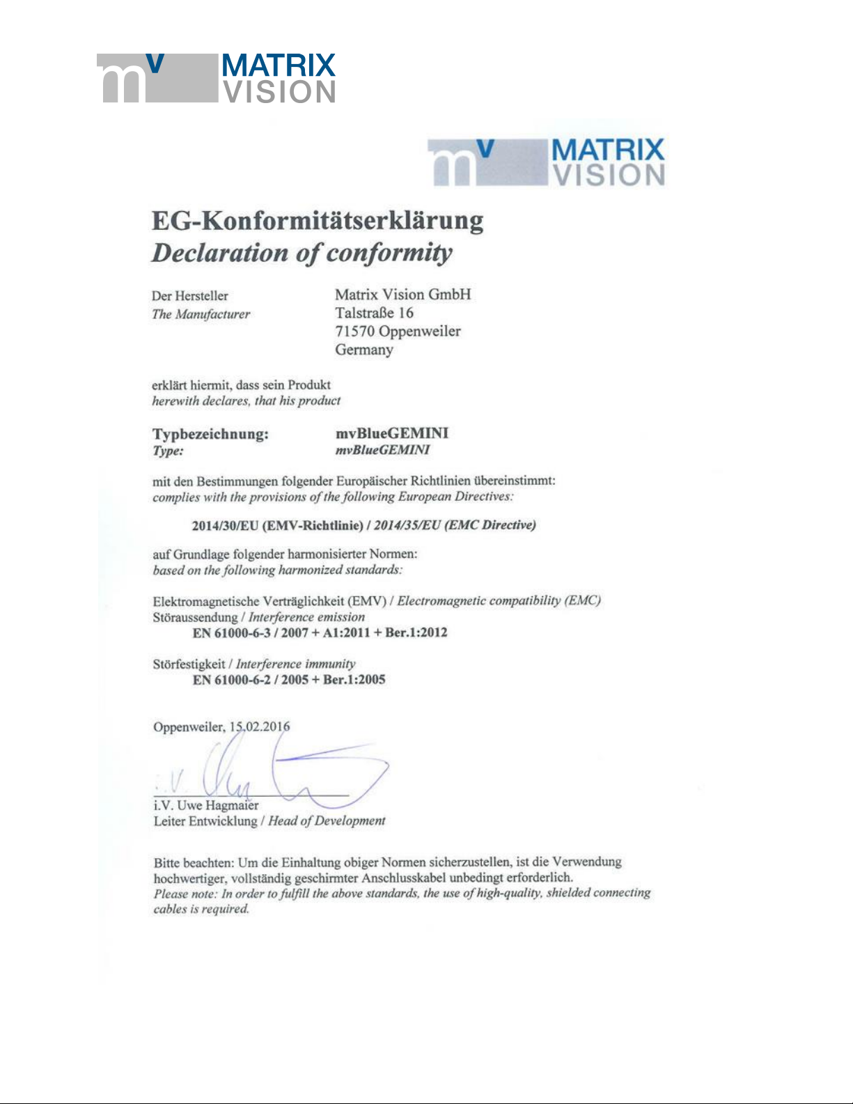
2014/30/EU (EMC Directive) based on the following harmonized standards
Electromagnetic compatibility (EMC)
Interference emission EN 61000-6-3 / 2007
Interference immunity EN 61000-6-2 / 2005
3 Notes, Warnings, Attentions
All due care and attention has been taken in preparing this manual. In view of our policy of
continuous product improvement, however, we can accept no liability for completeness and
correctness of the information contained in this manual. We make every effort to provide you with a
flawless product.
In the context of the applicable statutory regulations, we shall accept no liability for direct damage,
indirect damage or third-party damage resulting from the acquisition or operation of a MATRIX
VISION product. Our liability for intent and gross negligence is unaffected. In any case, the extend
of our liability shall be limited to the purchase price.
3.1 Declaration of Conformity statement
The manufacturer MATRIX VISION GmbH herewith declares, that this product complies with the
provisions of the following European Directives:
NOTES, WARNINGS, ATTENTIONS - DECLARATION OF CONFORMITY STATEMENT 6
Page 8
mvBlueGEMINI Technical Manual (EN) v1.2.2
NOTES, WARNINGS, ATTENTIONS - DECLARATION OF CONFORMITY STATEMENT 7
Page 9

mvBlueGEMINI Technical Manual (EN) v1.2.2
NOTES, WARNINGS, ATTENTIONS - DECLARATION OF CONFORMITY STATEMENT 8
Page 10

mvBlueGEMINI Technical Manual (EN) v1.2.2
Purpose of
this manual
This manual provides you with an overview of the smart camera's technical data
and the handling of the camera. For a quick summary of the product, we
recommend that you read the manual in the specified order.
Content of
this manual
In the section entitled "Proper use" the camera will be introduced, followed by the
camera's technical data and the scope of delivery.
The subsequent "First steps" section, you will learn how to plug in the camera and
how to connect it via your web browser. As soon as you are connected with the
camera, you can create an inspection program. Please consult the "mvIMPACT
Configuration Studio (mvIMPACT-CS) User Manual".
The next section Updates describes, how you can update the software of the smart
camera.
Technical details are explained in the Appendix and Glossary.
4 About this user manual
ABOUT THIS USER MANUAL - DECLARATION OF CONFORMITY STATEMENT 9
Page 11

mvBlueGEMINI Technical Manual (EN) v1.2.2
5 Proper use
The mvBlueGEMINI is a Smart Camera for creating inspection applications for different industrial
areas. The camera provides a user interface for connecting the camera via your web browser over
network. Furthermore you create and configure inspection programs with the user interface
software "mvIMPACT Configuration Studio (mvIMPACT-CS)". You can monitor and analyze the
results of the inspection program.
The user interface is kept simple and understandable in order to enable a fast learning process and
to allow intuitive working. You will find more details in the "mvIMPACT Configuration Studio
(mvIMPACT-CS) User Manual".
PROPER USE - DECLARATION OF CONFORMITY STATEMENT 10
Page 12

mvBlueGEMINI Technical Manual (EN) v1.2.2
Article name
Description
KS-RJ45-M12-8X x.xx
AL
Network cable, M12 connector, 8-pin X-coded, Cat.6A, length up to 20 m
KS-M12-PWR-IO xx.x
Shielded connection cable mvBlueGEMINI, M12 male connector to
prepared wires, UL/CSA, drag chain, up to 20 m
mv-X I/O-BOX
Break-out box for mvBlueGEMINI for connecting the camera and testing
of the digital inputs and outputs
MV-TRIPOD
ADAPTER GEMINI
Tripod adapter for mvBlueGEMINI
MV-TRIPOD ARM
1/4" Tripod with locking arm and two ball head joints
MV LENS TUBE
GEMINI 54
Lens protections tube, IP67, length 54mm
MV-DC2401 GEM IO
Power supply 24V / 1.5 A for mvBlueGEMINI with Dig. I/O on separate
cable, length Power 2.0m, I/O 1.0m
6 Scope of delivery
The scope of delivery includes the following components:
camera hardware
already installed configuration software mvIMPACT-CS (mvIMPACT Configuration Studio)
For connecting the camera, you will need the following accessories:
a suitable power supply (via suitable power supply unit or via suitable M12 cable conntected to
suitable power supply)
a suitable lens as well as
a suitablle network cable
According to the application environment, a separate lighting system could be required.
6.1 Accessories
SCOPE OF DELIVERY - ACCESSORIES 11
Page 13
mvBlueGEMINI Technical Manual (EN) v1.2.2
X
12 mm
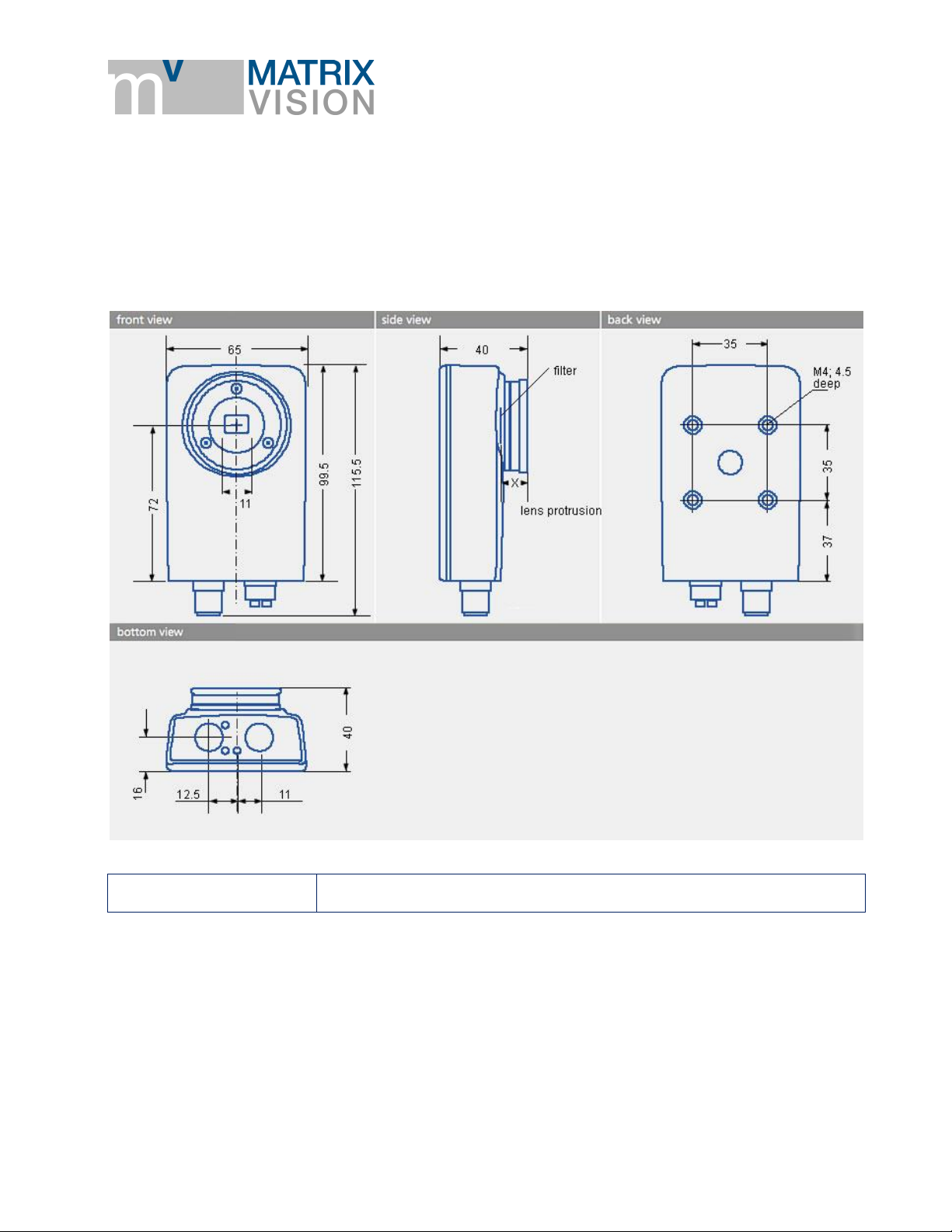
7 Technical data
7.1 Dimensional drawing
TECHNICAL DATA - DIMENSIONAL DRAWING 12
Page 14
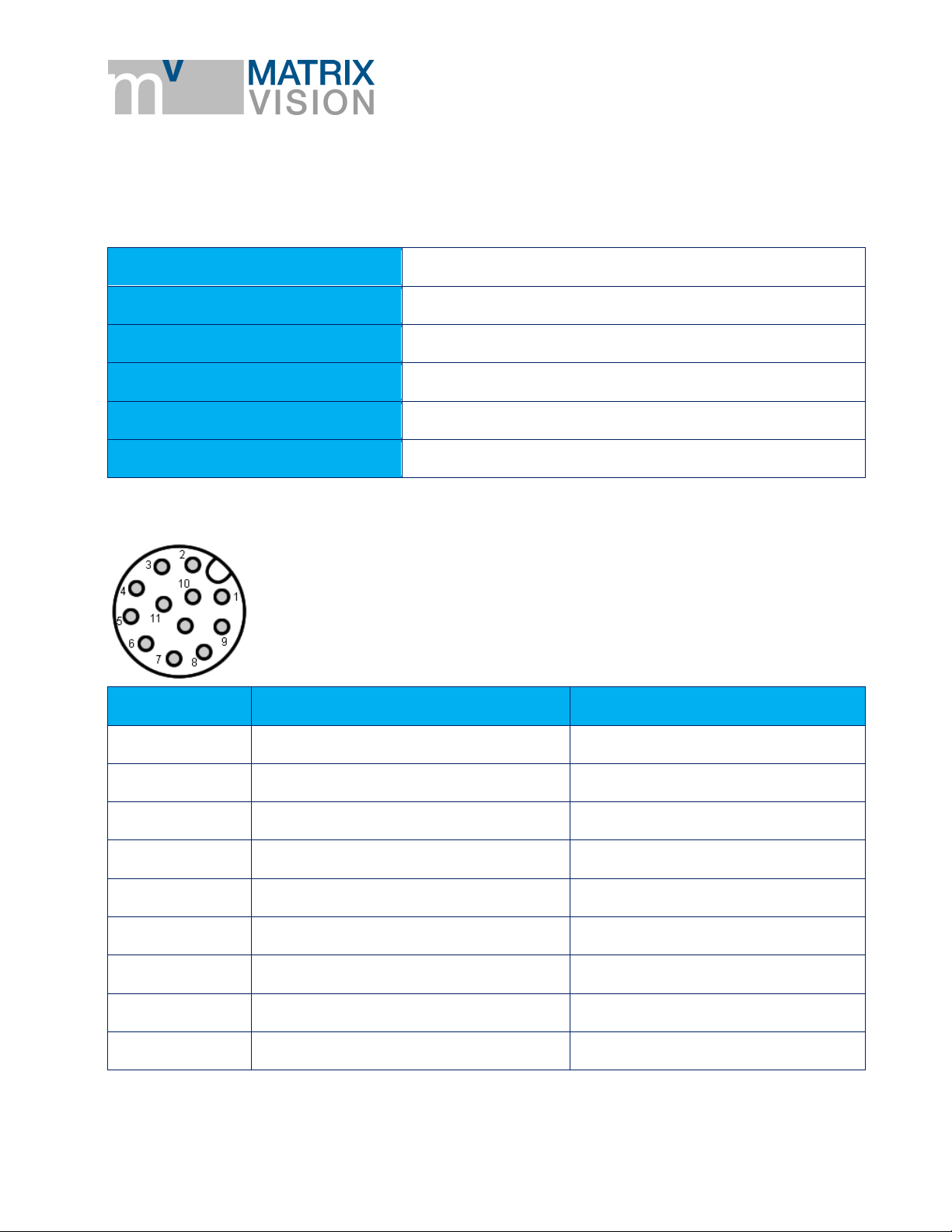
7.2 Connections
Manufacturer
Binder
Description
Flanschstecker, M12 x 1, 10,5 mm
Number of contacts
12
Area
M12-A
Order code
09 3491 550 12
713/763
Pin
Signal
Color
1
VIN_L+
brown
2
VIN_L-
blue
3
RS232RX
white
4
RS232TX
green
5
SPSIO1
pink
6
SPSGND
yellow
7
SPSIO0
black
8
SPSIO2
gray
9
SPSIO3
red
7.2.1 PWR/IO
Figure 1 Power / IO connector
mvBlueGEMINI Technical Manual (EN) v1.2.2
TECHNICAL DATA - CONNECTIONS 13
Page 15

mvBlueGEMINI Technical Manual (EN) v1.2.2
Pin
Signal
Color
10
SPSIO4
violet
11
SPSIO5
gray/pink
12
NC
red/blue
Delay time
typ. 3.3 µs
Delay time
typ. 6.3 µs
NOTE
Delay time can increase with higher load.
7.2.1.1 Characteristics of the I/Os
SPSIO0 - SPSIO5 are digital in-/outputs. Each of them could be used as an input, output,
trigger line or for controlling flash lights.
The inputs switch at approx. 11.3V (supply voltage > 18V; i.e. PLC).
The inputs switch at approx. 50% of the supply voltage (supply voltage <= 18V).
Max. output voltage for each output is 200mA.
Current limited output (< 450mA)
5 μs input filter for spike suppression
Reverse polarity protection
Overtemperature protection
Digital input
Measurement conditions: VCC = 24V
Digital output
Measurement conditions: VCC = 24V; RL = 1MΩ
TECHNICAL DATA - CONNECTIONS 14
Page 16
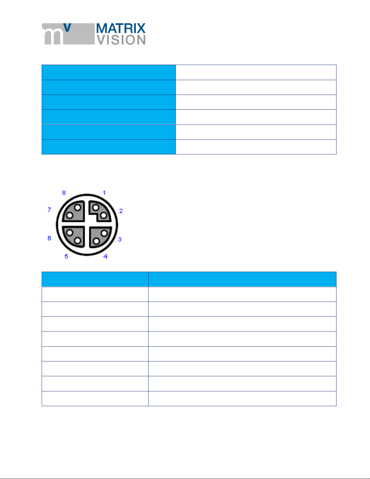
7.2.2 LAN
Manufacturer
Binder
Description
x-coded flange receptacle
Number of contacts
8
Area
M12-D, M12-X
Order code
99 3782 210 08
Serien 825/876
Pin
Signal
1
MDX0+
2
MDX0-
3
MDX1+
4
MDX1-
5
MDX3+
6
MDX3-
7
MDX2-
8
MDX2+
Figure 2 x-coded flange receptacle
mvBlueGEMINI Technical Manual (EN) v1.2.2
TECHNICAL DATA - CONNECTIONS 15
Page 17

NOTE
The Ethernet signals are galvanically isolated from the camera electronics.
7.3 LED states
Color
Description
Green
Power on
Green flashing
FPGA loaded.
Once software is running:
Software is in Configruation mode.
Green permanent
Inspection programm is running.
Red flashing
Software updating.
WARNING
DO NOT disconnect from power supply.
Red permanent
Software stalled, please reboot.
Color
Description
Green
Link
Orange flashing
Activity
7.3.1 PWR (Power)
mvBlueGEMINI Technical Manual (EN) v1.2.2
7.3.2 NET (Netzwerk)
7.3.3 I/O (Digital inputs and outputs
The LED "I/O" is not implemented in this software version.
TECHNICAL DATA - LED STATES 16
Page 18

7.4 Image sensor
CMOS
Model1
G / C
Resolution
1280 x 1024
MPixel
1.3
Shutter type
Pipelined / Global
Sensor size
1/1.8"
Unit cell size [µm]
5.3 x 5.3
Exposure time
10 µs - 1 s
ADC resolution / output
10 bit (10-8 companding) → 8 bit
SNR
41 dB
DR (normal / HDR)
62 dB / -
Trigger (HW / SW)
yes / yes
Spectral densitivity
Sensor manufacturer
E2V
Sensor name
EV76C560
mvBlueGEMINI Technical Manual (EN) v1.2.2
1
G = Gray scale, C = Color
TECHNICAL DATA - IMAGE SENSOR 17
Page 19

mvBlueGEMINI Technical Manual (EN) v1.2.2
7.5 Hardware
FPGA/SoC with Dual-Core Cortex-A9 each with 800 MHz
1 GB DDR3 SDRAM memory
4 GB NAND Flash
Connections:
o 1 GBit Ethernet LAN,
o 6 digital in-/outputs (valid modes: input, output, trigger, flash)
Size without lens (B x H x L): 65 x 40 x 99.5 mm
IP67
Power consumption less than 5W
Power supply: 12V to 24V DC +/- 10%
o Power consumption: 360mA @12V or 180mA @24V
Permissible ambient temperature
o operation: 0 °C .. +55 °C, without airflow
o storage: -25 °C .. +70 °C
RoHS
7.6 Software
Operating system: Linux®
Configuration software mvIMPACT Configuartion Studio (mvIMPACT-CS) with modern and
intuitive user interface
TECHNICAL DATA - HARDWARE 18
Page 20

mvBlueGEMINI Technical Manual (EN) v1.2.2
8 First steps
8.1 Connect the smart camera
Figure 3 Connector side
Connect the smart camera with the local network using the NET (2) connector .
Power the camera using the connector PWR/IO (1).
Now, the smart camera will start which will take approx. 30 seconds.
The smart camera will load the most recently opened inspection program and will continue with
the most recently used operating mode (active/inactive).
8.2 Connect with the smart camera
The camera is configured via PC, tablet or smartphone. It is assumed that the device used for
this purpose
o has a minimum resolution of 1024 x 768 pixels,
o has an supported web browser (Minimum: Mozilla Firefox Version 11 or Google
Chrome Version 16) and
FIRST STEPS - CONNECT THE SMART CAMERA 19
Page 21

mvBlueGEMINI Technical Manual (EN) v1.2.2
o is connected to the same network as the camera. In Windows, you need to apply the
setting "Obtain an IP address automatically" (DHCP) for the network adapter for the
PC or smart camera.
Access is then via the web browser. To go to the configuration software page,
a. open the web browser,
b. enter the address or URL of the device on which mvIMPACT-CS is running.
For the mvBlueGEMINI smart camera, this may look something like: "http://gemini-
000110".
c. Confirm your entries.
Please replace 000110 with the serial number of the used smart camera (without "MS").
You will find the serial number on the rear side of the camera printed on a label (starting
with "MS").
If there are other smart cameras in the network, you can also connect to them.
If you are connected to the smart camera correctly, you will see the homepage of mvIMPACT
Configuration Studios (mvIMPACT-CS).
Alternatively, you can use Windows Explorer to find the smart camera or the PC in the network. To
do this, select the network folder
, to display all connected network devices.
8.2.1 If you wish to access ICS in another subnetwork ...
Subnetworks have been explicitly created to arrange computers into various networks, with
these boundaries restricting access.
Refer to your IT administrator to set up access to the smart camera or PC. You can find useful
tips in the appendix "Notes about network connections".
8.3 How to continue?
You are connected to the smart camera via browser and the homepage of mvIMPACT
Configuration Studios (mvIMPACT-CS) is displayed. Now, you can create your first inspection
program with mvIMPACT-CS. For this, please consult the "mvIMPACT Configuration Studio
(mvIMPACT-CS) User Manual".
FIRST STEPS - HOW TO CONTINUE? 20
Page 22

mvBlueGEMINI Technical Manual (EN) v1.2.2
NOTE
We recommend updating the camera from time to time to derive maximum benefit from the
camera.
NOTE
Please note the correct entry of the characters \\.
NOTE
In rare cases, the username (address of the camera, e.g. \\gemini-000110) and the
corresponding password (blank password) will be requested.
ATTENTION
Do not switch off the camera during the update process. This may cause irremediable
damage to the camera.
9 Updates
9.1 Update software
Periodically, we publish software updates on our website. The updates contain bug fixes,
performance optimization, or functional extensions.
Please follow these steps to update the camera:
1. Download the latest update file from our website (https://www.matrix-vision.com/) and save it
locally on your computer.
2. Press the keys Windows + R, enter the address of the update directory (e.g. \\gemini-
000110\updates), and confirm with Enter.
3. Copy the update file into the folder updates. The update process will start automatically, which
can take up to 5 minutes. The LED status indicator "PWR (Power)" will flash red during the
update process and the camera is not available.
UPDATES - UPDATE SOFTWARE 21
Page 23

mvBlueGEMINI Technical Manual (EN) v1.2.2
4. After a few minutes, the update is finished and the LED status indicator "PWR (Power)" will
change to green. The camera is then ready to use.
UPDATES - UPDATE SOFTWARE 22
Page 24

mvBlueGEMINI Technical Manual (EN) v1.2.2
NOTE
To communicate via UDP, you have to set the Mode in the camera's system menu ("System
settings -> communication") to "UDP".
10 Appendix
10.1 Control commands
10.1.1 Communication via UDP
It is possible to control the smart camera using so-called UDP sockets via the Ethernet interface.
For this, the port 36701 is used.
The smart camera expects a Connect message to create a connection. Afterwards, the smart
camera will start to send result data. A Disconnect message closes the connection and the sender
of the Disconnect message has to close the socket.
The smart camera supports one active UDP connection. If a UDP connection exists, it will be
closed as soon as another Connect message is recieved. The camera ignores invalid messages.
10.1.1.1 Message structure
A message consists of unsigned 32 bit values and byte strings. They are transmitted in Little
Endian format and the lowest value byte is sent first.
There are three different message categories:
1. Messages from the smart camera
a. Result container
2. Messages to the smart camera without answer
a. Disconnect
b. Set input data
c. Trigger inspection
d. Start inspection
e. Stop inspection
f. Restart camera
g. Set inspection number
h. Set date and time
3. Messages to the smart camera with an answer after an action
APPENDIX - CONTROL COMMANDS 23
Page 25

mvBlueGEMINI Technical Manual (EN) v1.2.2
Lenght in bytes
Structure
Description
4
uint32
Magic number: 42565350
hex
4
uint32
User data length in bytes
4
uint32
Message ID
4
uint8[]
User data
ID
Message
01
hex
Connect
02
hex
Disconnect
20
hex
Result container
30
hex
Get program number
31
hex
Change inspection program
32
hex
Get date and time
33
hex
Set date and time
34
hex
Set input data
35
hex
Set inspection number
40
hex
Trigger inspection
41
hex
Start inspection
42
hex
Stop inspection
a. Connect
b. Change inspection
c. Get date and time
d. Get program number
All messages have the same structure:
Messages are ignored by the camera which do not comply with the given format (wrong "magic
number", wrong length, unknown message ID). The "magic number" is used to avoid accidential
transmissions. It is recommended to check the "magic number" in the control software.
Every message has a unique ID:
APPENDIX - CONTROL COMMANDS 24
Page 26

mvBlueGEMINI Technical Manual (EN) v1.2.2
ID
Message
43
hex
Restart camera
Lenght in bytes
Structure
Value
Description
4
uint32
42565350
hex
Magic number
4
uint32
00
hex
User data length in bytes
4
uint32
01
hex
Message ID
Lenght in bytes
Structure
Value
Description
4
uint32
42565350
hex
Magic number
4
uint32
04
hex
User data length in bytes
4
uint32
01
hex
Message ID
4
uint32
01
hex
Version of the protocol
Lenght in bytes
Structure
Value
Description
4
uint32
42565350
hex
Magic number
4
uint32
00
hex
User data length in bytes
4
uint32
02
hex
Message ID
Connect
The Connect message creates a connection to the smart camera.
The smart camera answers with a Connect message.
Disconnect
With the Disconnect message the connection will be disconnected. No more result data will be
transmitted.
APPENDIX - CONTROL COMMANDS 25
Page 27

mvBlueGEMINI Technical Manual (EN) v1.2.2
Lenght
in bytes
Structure
Value
Description
4
uint32
42565350
hex
Magic number
4
uint32
User data length in bytes
4
uint32
20
hex
Message ID
4
uint32
Inspection ID. The mvIMPACT Configuration Studio
(mvIMPACT-CS) can manage various inspection programs.
Each of this program has a unique inspection ID. This
section indicates the inspection, which created the result
container.
x
uint8[]
Result data as specified in mvIMPACT Configuration
Studio (mvIMPACT-CS) -> tool "Send results".
Lenght in bytes
Structure
Value
Description
4
uint32
42565350
hex
Magic Number
4
uint32
00
hex
User data length in bytes
4
uint32
30
hex
Message ID
Lenght in bytes
Structure
Value
Description
4
uint32
42565350
hex
Magic Number
4
uint32
04
hex
User data length in bytes
4
uint32
30
hex
Message ID
4
uint32
01
hex
Program ID
Result container
If an inspection program uses a "Send results" tool, the inspection program will send the result data
in this message after processing the inspection program.
Get program number
Gets the program number of the active inspection.
The smart camera answers with a status message containing the program number.
APPENDIX - CONTROL COMMANDS 26
Page 28

mvBlueGEMINI Technical Manual (EN) v1.2.2
Lenght in bytes
Structure
Value
Description
4
uint32
42565350
hex
Magic Number
4
uint32
04
hex
User data length in bytes
4
uint32
31
hex
Message ID
4
uint32
01
hex
Program ID
Lenght in bytes
Structure
Value
Description
4
uint32
42565350
hex
Magic Number
4
uint32
08
hex
User data length in bytes
4
uint32
31
hex
Message ID
4
uint32
00
hex
Status
4
uint32
01
hex
Program ID
Change Inspection program
A change is possible, when the following conditions are fulfilled.
No client is in the config mode.
The current inspection is stopped.
The number of the inspection program which should be loaded is not zero.
The inspection program which should be loaded is available on the camera.
No other inspection program is currently loaded or duplicated.
The smart camera answers with a status message containing the program number.
The status has a value of 00
gets loaded. In this case the program ID of the status message is equal to the number in the
change request. If one of the conditions is not fullfilled the inspection program is not changed. The
message then contains a status of 01
loaded.
if the mentioned conditions are fulfilled and the inspection program
hex
as well as the programm ID of the program that is still
hex
APPENDIX - CONTROL COMMANDS 27
Page 29

mvBlueGEMINI Technical Manual (EN) v1.2.2
Lenght in bytes
Structure
Value
Description
4
uint32
42565350
hex
Magic Number
4
uint32
00
hex
User data length in bytes
4
uint32
32
hex
Message ID
Lenght in bytes
Structure
Value
Description
4
uint32
42565350
hex
Magic Number
4
uint32
18hex
User data length in bytes
4
uint32
32
hex
Message ID
4
uint32
Year
4
uint32
Month
4
uint32
Day
4
uint32
Hour
4
uint32
Minute
4
uint32
Second
Lenght in bytes
Structure
Value
Description
4
uint32
42565350
hex
Magic Number
4
uint32
18hex
User data length in bytes
4
uint32
33
hex
Message ID
4
uint32
Year
4
uint32
Month
Get date and time
Get the current date and time from a smart camera.
The smart camera answers with the current date and time.
Set date and time
Set date and time on a smart camera.
APPENDIX - CONTROL COMMANDS 28
Page 30

mvBlueGEMINI Technical Manual (EN) v1.2.2
Lenght in bytes
Structure
Value
Description
4
uint32
Day
4
uint32
Hour
4
uint32
Minute
4
uint32
Second
To set date and time to 2016-06-25 10:11:12 send the following data (hex):
505356421800000033000000E007000006000000190000000A0000000B0000000C000000
Lenght in
bytes
Structure
Value
Description
4
uint32
42565350
hex
Magic number
4
uint32
User data length in bytes
4
uint32
34
hex
Message ID
4
uint8[]
Input data for the inspection as specified in mvIMPACT
Configuration Studio (mvIMPACT-CS).
Lenght in bytes
Structure
Value
Description
4
uint32
42565350
hex
Magic number
4
uint32
00
hex
User data length in bytes
4
uint32
40
hex
Message ID
The camera may discard or convert invalid values.
Set input data
Some inspections require input data which are compared with the acquired data of the smart
camera. These data can be sent to the smart camera using this message. The tool "Receive data"
interprets the input data.
Trigger inspection
Is sent to the smart camera to trigger an inspection.
APPENDIX - CONTROL COMMANDS 29
Page 31

mvBlueGEMINI Technical Manual (EN) v1.2.2
Lenght in bytes
Structure
Value
Description
4
uint32
42565350
hex
Magic number
4
uint32
00
hex
User data length in bytes
4
uint32
41
hex
Message ID
Lenght in bytes
Structure
Value
Description
4
uint32
42565350
hex
Magic number
4
uint32
00
hex
User data length in bytes
4
uint32
42
hex
Message ID
Lenght in bytes
Structure
Value
Description
4
uint32
42565350
hex
Magic number
4
uint32
00
hex
User data length in bytes
4
uint32
43
hex
Message ID
Start inspection
Is sent to the smart camera to start the inspection. The behavior of the smart camera depends on
the mvIMPACT Configuration Studio (mvIMPACT-CS) settings. Untriggered inspections will start
immediately and will transmit results continuously while triggered inspections will wait for a trigger
signal.
Stop inspection
Is sent to the camera to stop an inspection. Untriggered inspections will stop and will not send
results anymore while triggered inspections will ignore further trigger signals.
Restart camera
Restarts the camera. After this message, the network connection will be lost and will be established
after the restart. The restart will take approximately 30 seconds.
APPENDIX - CONTROL COMMANDS 30
Page 32

mvBlueGEMINI Technical Manual (EN) v1.2.2
Lenght in bytes
Structure
Value
Description
4
uint32
42565350
hex
Magic number
4
uint32
04
hex
User data length in bytes
4
uint32
35
hex
Message ID
4
uint32
01
hex
Inspection number
# Connect
echo -n -e '\x50\x53\x56\x42\x00\x00\x00\x00\x01\x00\x00\x00' | nc uw 1 -p 60001 192.168.1.230 36701
# Start inspection:
echo -n -e '\x50\x53\x56\x42\x00\x00\x00\x00\x41\x00\x00\x00' | nc uw 1 -p 60001 192.168.1.230 36701
# Stop inspection:
echo -n -e '\x50\x53\x56\x42\x00\x00\x00\x00\x42\x00\x00\x00' | nc uw 1 -p 60001 192.168.1.230 36701
# Disconnect:
echo -n -e '\x50\x53\x56\x42\x00\x00\x00\x00\x01\x00\x00\x00' | nc -
uw 1 -p 60001 192.168.1.230 36701
Set inspection number
Set the inspection number for the next inspection.
10.1.1.2 Testing the communication
Under Linux
For testing the UDP communication you can use the tool Netcat under Linux. The following console
prompts will open a connection to the camera, start and stop the current inspection, and close the
connection.
In this example the IP address of the smart camera is 192.168.1.230. The port 60001 is used to get
results from the camera.
Under Windows
For testing the UDP communication you can use the tool Packet Sender
(https://packetsender.com) under Windows. The following console prompts will open a connection
to the camera, start and stop the current inspection, and close the connection.
In this example the IP address of the smart camera is 192.168.1.230.
APPENDIX - CONTROL COMMANDS 31
Page 33

mvBlueGEMINI Technical Manual (EN) v1.2.2
Figure 4 Packet Sender - for testing the UDP communication
APPENDIX - CONTROL COMMANDS 32
Page 34

mvBlueGEMINI Technical Manual (EN) v1.2.2
Error
Cause
Action
No connection to
the camera
possible
Incorrect network
configuration
Check and implement the measures defined in the
"Notes on network connections" chapter.
Alternative access to the camera (direct connection):
1. Disconnect the camera's power supply.
2. Use a PC/laptop with an Ethernet port.
3. Disconnect the PC from all networks by removing
all network cables and disabling the WLAN (if
present).
4. Establish a direct connection between the PC and
the camera by connecting the camera's network
cable directly to the PC's Ethernet port. Do not use
any switches/routers/hubs.
5. Restore the camera's power supply.
6. The camera now starts up and establishes a
network address with the connected PC. This may
take up to 5 minutes.
7. Follow the sequence mentioned in the "First steps"
chapter under "Connecting with the smart camera"
8. Open the system settings and check the camera's
network configuration. In case of doubt, consult an
IT expert.
No connection to
the camera
possible
Incorrect
configuration of PC -
Wrong IP address
If you cannot get an connection to the camera as
described before, it could be possible, that your
PC/laptop doesn't find the camera because it doesn't
negotiate an IP address with the camera. Please
ensure that your PC retrieves it's IP address
automatically (DHCP):
1. Open the settings of your network adapter and
there the settings of the internet protocoll
(TCP/version 4)
2. Set the IP address to automatically
3. Inside the tab alternative configuration also set the
IP address to autmatically
10.2 Troubleshooting table
APPENDIX - TROUBLESHOOTING TABLE 33
Page 35

mvBlueGEMINI Technical Manual (EN) v1.2.2
Error
Cause
Action
4. Close the windows and restart the PC
5. Retry the previously described way
No connection to
the camera
possible
Incorrect
configuration of PC -
NetBIOS name
(http://gemini-
nnnnnn) of the smart
camera is not
dissolved
If you still cannot get an connection to the camera as
described before, it could be possible, that your
PC/laptop cannot dissolve the NetBIOS name
(http://gemini-nnnnnn) of the smart camera.
Please check the "Node Type" of your PC:
1. Open the command promt of your system.
2. Enter ipconfig /all.
You will find the entry "Node Type" in "Windows
IP Configuration". Here should be "Hybrid".
Otherwise, change the entry in the following way:
https://msdn.microsoft.com/enus//library/cc757386(v=ws.10).aspx
If you still cannot connect to the camera, using Intel
network cards, try to install the driver without "Intel
PROSet for Windows Device Manager" and without
"Advanced Network Services" or to deinstall both
options.
No connection to
the camera
possible
(especially with
laptops)
Incorrect
configuration of PC -
NetBIOS name
(http://gemini-
nnnnnn) of the smart
camera is not
dissolved because of
a WiFi connection
Because of a WiFi connection, the DNS server of your
internet service provider is used to resolve the
NetBIOS name (http://gemini-nnnnnn) of the smart
camera. The DNS server, of course, does not know
the address http://gemini-nnnnnn and responds with
an error messsage.
Please
1. turn off the WiFi module and
2. reboot the laptop.
Now, you can check, if the camera was resolved
using the Windows shell:
1. Click on the Windows start button and
2. enter cmd.
3. Enter nbtstat -c.
All resolved NetBIOS names will be listed and you
should find the smart camera there:
APPENDIX - TROUBLESHOOTING TABLE 34
Page 36

mvBlueGEMINI Technical Manual (EN) v1.2.2
Error
Cause
Action
C:\Users\war>nbtstat -c
Ethernet:
Node IpAddress: [0.0.0.0] Scope Id:
[]
No names in cache
Local Area Connection:
Node IpAddress: [169.254.93.40]
Scope Id: []
NetBIOS Remote
Cache Name Table
Name Type
Host Address Life [sec]
-------------------------------
---------------------------- GEMINI-NNNNNN <20> UNIQUE
169.254.4.9 540
GEMINI-NNNNNN <00> UNIQUE
169.254.4.9 549
You can also reach the camera with the IP address
directly (in this sample 169,254.4.9).
Connection to the
camera possible,
however a dialog
appears, that the
connection to the
camera was lost
Firewall active
Please add http://gemini-* as trusted web addresses
to your firewall settings.
Action menu
"Monitor": No
fluent display or
freeze of the
browser
Display device is too
weak
Deactivate the live image diplay:
1. Change to the action menu "Configuration".
2. Select the Tool "Get image".
3. Deactivate the checkbox "outImage" in the result
table.
4. Repeat this step for every used "Get image" and
"Find object" tool.
APPENDIX - TROUBLESHOOTING TABLE 35
Page 37

mvBlueGEMINI Technical Manual (EN) v1.2.2
Error
Cause
Action
10.3 Notes on network connections
10.3.1 Background information
The user would like to connect to the smart camera with their client via web browser. For this to
work,
1. the smart camera's IP address or host name must be known or found, and
2. a data packet route to this IP address or host name must exist.
Point 2 is relatively simple, as only a single route has to exist between the client and the server.
Routers (and routing tables) as well as port forwarding are available for this purpose. However, for
point 1, conveniently locating the smart camera, the mDNS broadcasts must be available, which is
normally suppressed by routers. The server essentially publishes its settings via Avahi and mDNS.
The client can initially use the host name printed on the smart camera.
Different problems need to be overcome with different solutions depending on the network
topology. These are discussed below.
10.3.2 Terms (simplified description)
Switch is a simple distributor of network packages in a subnet. Both mDNS packages as well
as packages directly on another computer are permitted.
Router separates subnets, i.e. a router can forward queries from one subnet to another subnet.
NAT is generally used, i.e. the router replaces the querying IP address with its own. This means
that external access to the computer behind the router is not possible. mDNS broadcasts are
also not transmitted.
Firewall behaves in a similar manner to a router, but it also filters the content of the network
packages.
10.3.3 Server and client not separated by a firewall
10.3.3.1 Server and client live in the same subnet (e.g. DHCP or fixed IP)
The server now has the problem of having to find the IP address. The possible solutions are:
In the case of DHCP, the IP address can be read out in the DHCP server, but requires read
rights to the DHCP server.
APPENDIX - NOTES ON NETWORK CONNECTIONS 36
Page 38

mvBlueGEMINI Technical Manual (EN) v1.2.2
Start the delivered script and display an overview of the smart camera. Select a smart camera
and access its URL via web browser.
Start a local instance of the ICS server (offline version) and connect with "localhost" via web
browser. Then select the desired smart camera in the browser.
Call up a central but local instance in the intranet. This is where a small web server is running,
which identifies all smart cameras in the local network via Avahi and makes them available for
selection.
10.3.3.2 Server uses a Zero-Conf address and a fixed IP in an external subnet
The client then also has to use a Zero-Conf address (set "dynamic IP address" under Windows with
no DHCP server in the network). This can be achieved by connecting the camera directly to the
client PC. The second or third solution from "Server and client live in the same subnet (e.g. DHCP
or fixed IP)" can then be used.
10.3.3.3 Server and client live in different IP subnets
The mDNS packages are not transmitted beyond subnet boundaries as standard. The possible
solutions are:
An additional (Linux) computer, which connects both subnets, i.e. has access to both subnets
and is configured so that it forwards mDNS queries to the other subnet (=Avahi reflector), is
required.
APPENDIX - NOTES ON NETWORK CONNECTIONS 37
Page 39

mvBlueGEMINI Technical Manual (EN) v1.2.2
10.3.4 Server and client separated by a firewall
In this case, the server and client are in different IP subnets without loss of generality.
10.3.4.1 Static port forwarding
The easiest access to a smart camera behind a firewall is established by port forwarding. In this
case, the firewall forwards all queries on one of its ports to a specific smart camera port, i.e. this
forwarding must be manually configured for every smart camera. The Avahi service is not used.
The client accesses the open firewall port externally.
10.3.4.2 Reverse proxy with dynamic subdomains
An Avahi service is also running on the reverse proxy web server, which automatically publishes all
smart cameras as subdomains and makes these available in its function as a reverse proxy. The
reverse proxy also requires port forwarding to be set up in the firewall (see
https://confluence.matrix-vision.com/x/ewKW).
APPENDIX - NOTES ON NETWORK CONNECTIONS 38
Page 40

mvBlueGEMINI Technical Manual (EN) v1.2.2
10.3.4.3 OpenVPN as a bridge between two subnets
An OpenVPN server functions as a bridge and connects two subnets (see
http://www.heise.de/netze/artikel/Bridge-Modus-224072.html and https://docs.openvpn.net/how-totutorialsguides/virtual-platforms/site-to-site-layer-2-bridging-using-openvpn-access-server/). In this
case, the two Open VPN servers must be configured so that they transmit direct network packages
as well as mDNS broadcasts. This either takes place by establishing forwarding as is the case in
"Server and client live in different IP subnets" or configuring the VPN so that the client and server
are located in the same subnet.
Versions with OpenVPN client
APPENDIX - NOTES ON NETWORK CONNECTIONS 39
Page 41

mvBlueGEMINI Technical Manual (EN) v1.2.2
Versions with OpenVPN bridge
APPENDIX - NOTES ON NETWORK CONNECTIONS 40
Page 42

mvBlueGEMINI Technical Manual (EN) v1.2.2
APPENDIX - NOTES ON NETWORK CONNECTIONS 41
Page 43

mvBlueGEMINI Technical Manual (EN) v1.2.2
Image field
Diagonal
4/3 inch
17.3 mm * 13.0 mm
23 mm
1 inch
12.8 mm * 9.6 mm
16 mm
2/3 inch
8.8 mm * 6.6 mm
11 mm
1/1,8 inch
6.7 mm * 5.4 mm
8,61 mm
1/2 inch
6.4 mm * 4.8 mm
8 mm
1/3 inch
4.8 mm * 3.6 mm
6 mm
1/4 inch
3.2 mm * 2.4 mm
4 mm
10.4 Choice of the right lens and lighting system
10.4.1 Find the correct lens
Lenses are the starting point of the image processing signal path and shape the light information.
The better the optics and the more time you've invested in this issue, the better the source material
for the image processing. In the following you will find an overview of the essential properties, sizes
and contexts.
10.4.1.1 Limits and settings of a lens
Image field size
With the image filed sizes you can extract first information about the boundary conditions of an
image. Here, the focal length of a normal lens corresponds to the diagonal of the image field.
For example, an 8 mm lens behaves like a wide angle lens in combination with a 1 inch sensor. In
contrast, the same lens behaves like a telephoto lens in combination with a 1/4 inch sensor. For
industrial purposes, sensor sizes from 1 inch and smaller are common.
Components of a lens
Using a lens, the focal length defines the image angle and for this reason the scale between
object and image.
You can adapt two properties of the lens:
Focus
o a sharp image is possible even with different object distances
o a scale on the lens indicates distance between object and image (from the minimum
distance to infinity)
o a closer focus is possible using spacers
APPENDIX - CHOICE OF THE RIGHT LENS AND LIGHTING SYSTEM 42
Page 44

mvBlueGEMINI Technical Manual (EN) v1.2.2
M = F * A
A = M / F => A = 0.1 / 2 = 0.05
A = V * P
V = A / P => V = 0.05 / 0.0053 = 9.43 (~ 10)
Accuracy of measurement
Resolution
Number of points
Object field
Size of the object
2 µ
1 µ
4000 x 2600
4 mm * 2.6 mm
20 µ
10 µ
4000 x 2600
40 mm * 26 mm
40 µ
20 µ
4000 x 2600
80 mm * 52 mm
200 µ
100 µ
4000 x 2600
400 mm * 260 mm
Aperture
o an opening through which light travels (narrow aperture = less light)
o a scale indicates the f-number (high value = narrow aperture)
o has direct impact on the imaging quality (determines resolution and depth of field).
Calculate the image
Using the formula for a single lens is the easiest way to calculate an image. At least, it is possible to
indicate the boundary conditions for a test setup's concept.
The accuracy of measurement specifies how many measuring points are needed in the object. With
it and setting the image detail, you can determine the camera.
Example: If an accuracy (M) of 0.1 mm is needed, you have to use twice as many resolution points
(F; according to the sampling theorem), which results in a measurement resolution (A) of 0.05 mm:
The sensor of the mvBlueGEMINI has a pixel size (P) of 0.0053 mm (5.3 µm), which will lead to an
image scale of approx. 1/10:
With the sensor size of 6.7 mm * 5.4 mm (1/1.8 inch), you can view an object of 67 mm * 54 mm in
an image.
Example of further such correlations:
With these considerations you can check, if you can image the object with the camera's sensor.
APPENDIX - CHOICE OF THE RIGHT LENS AND LIGHTING SYSTEM 43
Page 45

mvBlueGEMINI Technical Manual (EN) v1.2.2
f = g * B / (G + B)
f / g = B / G # if G > 10 * B
Choice of the lens
You can calculate further parameters using the following formula (the focal length with the given
object distance, or with the given focal length the object distance):
Figure 5 Focal length formula
If the size of the sensor (B), the size of the object (G), and the object distance (g) are known, you
can calculate the needed focal length.
For a rough calculation a swift procedure is enough. If the object distance is noticeably larger than
the focal length, you will have the image scale immediately.
On our website, we offer a lens calculator:
APPENDIX - CHOICE OF THE RIGHT LENS AND LIGHTING SYSTEM 44
Page 46

mvBlueGEMINI Technical Manual (EN) v1.2.2
http://www.matrix-vision.com/lens-calculator.html
Because single lenses have strong aberrations, several lenses are used to compensate these
errors.
The wavelength of the light has a great influence on the image. For each wavelength, the image
quality is good and/or is sharp in different spots.
By the use of the mentioned corrections with several lenses, it is tried to consolidate these levels.
An achromatic lens, for example. is a lens with two corrected colors. Other wavelengths vary
from it a bit.
An apochromatic lens is a lens which is optimized for three wavelengths.
APPENDIX - CHOICE OF THE RIGHT LENS AND LIGHTING SYSTEM 45
Page 47

Figure 6 Lens correction
e = g + h + b
mvBlueGEMINI Technical Manual (EN) v1.2.2
Zoom lenses ofter consist of 10 or more lenses.
Real lenses have an entrance pupil and an exit pupil. The parameters b and g are calculated
starting from these levels. If the distance of the levels equals h (also called main level), the total
setting distance e is between object and image.
h equals 0 with a single lens.
APPENDIX - CHOICE OF THE RIGHT LENS AND LIGHTING SYSTEM 46
Page 48

Figure 7 Setting level
Distance between lens and image = focal length
B = 1.22 * 2 * λ * F / D
mvBlueGEMINI Technical Manual (EN) v1.2.2
The parameter h is usually not known. With the mvBlueGEMINI, h is usually very small.
For this reason, the formula without h is used in test setup concepts.
It should be possible to set every lens to infinity. In this case, the
Therefore, each lens should be fixed in a different way. To avoid this, camera classes have fixed
distances, called flange focal distance. C-mount lenses, for example, have a flange focal distance
of 17.5 mm, which is independent from the focal length (CS-mount = 12.5 mm). With the help of
adapters, lenses with longer flange focal distances can be mounted on cameras with shorter
distances. This will not work vice versa because you will not reach infinity then.
The resolution - a little physics
Actually, you have to consider the wavelength of the light, because the light makes the image.
The wavelength of the visible light is between 0.4 µm and 0.6 µm.
The smallest imaged point results from the aperture which will never be smaller than 0.5 µm.
Realistic figures are between 2 µm and 5 µm.
APPENDIX - CHOICE OF THE RIGHT LENS AND LIGHTING SYSTEM 47
Page 49

mvBlueGEMINI Technical Manual (EN) v1.2.2
B = Diffraction disk or point image
F = Focal length
D = Aperture diameter
F-number F/D
Diameter diffraction disk
1
1.25 µm
4
5 µm
16
20 µm
Effects
Light specifications
Without
structure
light on object
light as a contrast to the object
no information by the light
information from the object
must be homogeneous
must be time stable
must be broadband in
color
With structure
underlines specific characteristics
color changes contrast of details
projected lines perform a coordinate
transformation
usually disturbing reflections become
information
is definied structured
is limited to light bands
Example with green light and λ = 0.5 µm
10.4.2 Find the correct lighting system
Besides optics, the illumination is an important point, which is critical for good results in the image
processing. The golden rule is: create contrast.
A lighting system can be homogeneous or structured. Following table shows the effects and the
characteristics of lighting systems:
APPENDIX - CHOICE OF THE RIGHT LENS AND LIGHTING SYSTEM 48
Page 50

mvBlueGEMINI Technical Manual (EN) v1.2.2
Direction
Angle
Applications
Speciality
Background
lighting
Bright
field
transparent and opaque as well as
flat or spatial parts
often in combination with diffuse or
telecentric lighting
suitable for testing bore holes
Preferred lighting system for
presence monitoring (binary
image)
uniformly bright, high-contrast
image
almost binary attributes
Dark
field
Transparent test objects like glass
or plastics
Very small distance between test
objects and lens possible
surface characteristics as
light details on a dark
background
10.4.2.1 Direction of the light
Figure 8 Direction of the light
Source: https://wiki.zimt.uni-
siegen.de/fertigungsautomatisierung/index.php/Beleuchtungstechniken_f%C3%BCr_die_industriell
e_Bildverarbeitung
According to the direction, there are different possible uses:
APPENDIX - CHOICE OF THE RIGHT LENS AND LIGHTING SYSTEM 49
Page 51

mvBlueGEMINI Technical Manual (EN) v1.2.2
Direction
Angle
Applications
Speciality
Incident
lighting
Bright
field
suitable for transparent and
opaque parts (glass, metal,
plastics)
also suitable for rough, poorly
reflecting surfaces
uniformly bright, well-
contrasted image
possible with coaxial mirror
lighting
Dark
field
emphasizing shapes, scratches,
cracks, etc.
determines both, engraved and
raised structures
suitable for transparent and
opaque parts
particularly suitable for surface
inspections, also highly reflective
parts
difficult with dirt
Dimensions
Illuminant
Procedure
Speciality
0
Light point
Triangulation
light beam is sent to the surface obliquely
if the object's distance changes in front of the
lens, the point where the light passes the lens will
move laterally
the lateral movement will be displayed and
measured
the lateral offset of the image is a measure for the
change in distance
1
Light line
Light section
method
oblique projection
translate depth information in image coordinates
(e.g. z in x)
expand the triangulation principle to many parallel
measurements (here the Y coordinate)
10.4.2.2 Lighting structure
Besides homogenous light there are following lighting structures:
APPENDIX - CHOICE OF THE RIGHT LENS AND LIGHTING SYSTEM 50
Page 52

Dimensions
Illuminant
Procedure
Speciality
2
Light grid
Grid projection
method
phase shift process returns dense spatial
information
10.4.2.3 Further factors
Further factors of lighting systems are:
wavelength
o color
type of lamp
o incandescent lamp
o discharge lamp
o LED
mvBlueGEMINI Technical Manual (EN) v1.2.2
long-term behavior
o aging
o pollution
short-term behavior
o AC/DC supply
o radio-frequency operation
o flash
APPENDIX - CHOICE OF THE RIGHT LENS AND LIGHTING SYSTEM 51
 Loading...