

Page 1
mvBlueFOX3
Technical Manual
English - Version 1.41
Page 2

CONTENTS i
Contents
1 About this manual 2
1.1 Goal of the manual . . . . . . . . . . . . . . . . . . . . . . . . . . . . . . . . . . . . . . . . . . 2
1.2 Contents of the manual . . . . . . . . . . . . . . . . . . . . . . . . . . . . . . . . . . . . . . . . 2
2 Imprint 4
2.1 Introduction . . . . . . . . . . . . . . . . . . . . . . . . . . . . . . . . . . . . . . . . . . . . . . 5
2.2 wxWidgets . . . . . . . . . . . . . . . . . . . . . . . . . . . . . . . . . . . . . . . . . . . . . . . 5
2.3 Sarissa . . . . . . . . . . . . . . . . . . . . . . . . . . . . . . . . . . . . . . . . . . . . . . . . 5
2.4 GenICam . . . . . . . . . . . . . . . . . . . . . . . . . . . . . . . . . . . . . . . . . . . . . . . 5
2.5 libusb . . . . . . . . . . . . . . . . . . . . . . . . . . . . . . . . . . . . . . . . . . . . . . . . . 5
2.6 libusbK . . . . . . . . . . . . . . . . . . . . . . . . . . . . . . . . . . . . . . . . . . . . . . . . . 5
2.6.1 libusbK license . . . . . . . . . . . . . . . . . . . . . . . . . . . . . . . . . . . . . . . . 6
2.7 Doxygen . . . . . . . . . . . . . . . . . . . . . . . . . . . . . . . . . . . . . . . . . . . . . . . . 6
2.7.1 Doxygen license . . . . . . . . . . . . . . . . . . . . . . . . . . . . . . . . . . . . . . . 6
2.8 SHA1 algorithm . . . . . . . . . . . . . . . . . . . . . . . . . . . . . . . . . . . . . . . . . . . . 7
2.9 Expat . . . . . . . . . . . . . . . . . . . . . . . . . . . . . . . . . . . . . . . . . . . . . . . . . 7
2.9.1 Expat Copyright . . . . . . . . . . . . . . . . . . . . . . . . . . . . . . . . . . . . . . . . 7
2.10 OpenSSL . . . . . . . . . . . . . . . . . . . . . . . . . . . . . . . . . . . . . . . . . . . . . . . 7
2.10.1 OpenSSL License Issues . . . . . . . . . . . . . . . . . . . . . . . . . . . . . . . . . . . 7
2.10.2 OpenSSL License . . . . . . . . . . . . . . . . . . . . . . . . . . . . . . . . . . . . . . . 8
2.11 CppUnit . . . . . . . . . . . . . . . . . . . . . . . . . . . . . . . . . . . . . . . . . . . . . . . . 8
2.12 NUnit . . . . . . . . . . . . . . . . . . . . . . . . . . . . . . . . . . . . . . . . . . . . . . . . . 8
2.12.1 NUnit License . . . . . . . . . . . . . . . . . . . . . . . . . . . . . . . . . . . . . . . . . 9
3 Legal notice 10
3.1 Introduction . . . . . . . . . . . . . . . . . . . . . . . . . . . . . . . . . . . . . . . . . . . . . . 10
3.2 cJSON . . . . . . . . . . . . . . . . . . . . . . . . . . . . . . . . . . . . . . . . . . . . . . . . . 10
3.2.1 cJSON license . . . . . . . . . . . . . . . . . . . . . . . . . . . . . . . . . . . . . . . . 10
3.3 Unity . . . . . . . . . . . . . . . . . . . . . . . . . . . . . . . . . . . . . . . . . . . . . . . . . . 10
3.3.1 Unity license . . . . . . . . . . . . . . . . . . . . . . . . . . . . . . . . . . . . . . . . . 10
MATRIX VISION GmbH
Page 3

ii CONTENTS
4 Revisions 12
5 Graphic Symbols 19
5.1 Notes, Warnings, Attentions . . . . . . . . . . . . . . . . . . . . . . . . . . . . . . . . . . . . . . 19
5.2 Webcasts . . . . . . . . . . . . . . . . . . . . . . . . . . . . . . . . . . . . . . . . . . . . . . . 19
6 Important information 20
6.1 Important safety instructions . . . . . . . . . . . . . . . . . . . . . . . . . . . . . . . . . . . . . 20
6.2 Operating considerations . . . . . . . . . . . . . . . . . . . . . . . . . . . . . . . . . . . . . . . 20
6.2.1 Important safety notes . . . . . . . . . . . . . . . . . . . . . . . . . . . . . . . . . . . . 20
6.2.2 Handling and cleaning . . . . . . . . . . . . . . . . . . . . . . . . . . . . . . . . . . . . 21
6.2.3 Installing . . . . . . . . . . . . . . . . . . . . . . . . . . . . . . . . . . . . . . . . . . . 21
6.2.4 Optimizing performance and life time . . . . . . . . . . . . . . . . . . . . . . . . . . . . . 21
6.2.5 Connectors . . . . . . . . . . . . . . . . . . . . . . . . . . . . . . . . . . . . . . . . . . 21
6.2.6 Cleaning . . . . . . . . . . . . . . . . . . . . . . . . . . . . . . . . . . . . . . . . . . . 22
6.2.7 Adjusting the C-mount (mvBlueFOX3-2xxx-1xxx) . . . . . . . . . . . . . . . . . . . . . . 22
6.2.8 Adjusting the C-mount (mvBlueFOX3-2xxx-2xxx) . . . . . . . . . . . . . . . . . . . . . . 23
6.3 European Union Declaration of Conformity statement . . . . . . . . . . . . . . . . . . . . . . . . 23
6.4 Legal notice . . . . . . . . . . . . . . . . . . . . . . . . . . . . . . . . . . . . . . . . . . . . . . 28
6.4.1 For customers in the U.S.A. . . . . . . . . . . . . . . . . . . . . . . . . . . . . . . . . . . 28
6.4.2 For customers in Canada . . . . . . . . . . . . . . . . . . . . . . . . . . . . . . . . . . . 29
6.4.3 Pour utilisateurs au Canada . . . . . . . . . . . . . . . . . . . . . . . . . . . . . . . . . 29
7 Introduction 30
7.1 Software concept . . . . . . . . . . . . . . . . . . . . . . . . . . . . . . . . . . . . . . . . . . . 30
7.2 Order code nomenclatures . . . . . . . . . . . . . . . . . . . . . . . . . . . . . . . . . . . . . . 31
7.2.1 mvBlueFOX3 . . . . . . . . . . . . . . . . . . . . . . . . . . . . . . . . . . . . . . . . . 31
7.2.2 mvBlueFOX3-M1 . . . . . . . . . . . . . . . . . . . . . . . . . . . . . . . . . . . . . . . 32
7.2.3 mvBlueFOX3-M2 . . . . . . . . . . . . . . . . . . . . . . . . . . . . . . . . . . . . . . . 33
7.2.4 Ordering code samples . . . . . . . . . . . . . . . . . . . . . . . . . . . . . . . . . . . . 33
7.3 What's inside and accessories . . . . . . . . . . . . . . . . . . . . . . . . . . . . . . . . . . . . 33
7.3.1 Accessories for the mvBlueFOX3 . . . . . . . . . . . . . . . . . . . . . . . . . . . . . . . 34
MATRIX VISION GmbH
Page 4

CONTENTS iii
8 Quickstart 35
8.1 Driver concept . . . . . . . . . . . . . . . . . . . . . . . . . . . . . . . . . . . . . . . . . . . . . 35
8.1.1 NeuroCheck support . . . . . . . . . . . . . . . . . . . . . . . . . . . . . . . . . . . . . 36
8.1.2 VisionPro support . . . . . . . . . . . . . . . . . . . . . . . . . . . . . . . . . . . . . . . 37
8.1.3 HALCON support . . . . . . . . . . . . . . . . . . . . . . . . . . . . . . . . . . . . . . . 37
8.1.4 LabVIEW support . . . . . . . . . . . . . . . . . . . . . . . . . . . . . . . . . . . . . . . 37
8.1.5 DirectShow support . . . . . . . . . . . . . . . . . . . . . . . . . . . . . . . . . . . . . . 37
8.1.6 Micro-Manager support . . . . . . . . . . . . . . . . . . . . . . . . . . . . . . . . . . . . 37
8.2 Windows . . . . . . . . . . . . . . . . . . . . . . . . . . . . . . . . . . . . . . . . . . . . . . . . 38
8.2.1 System requirements . . . . . . . . . . . . . . . . . . . . . . . . . . . . . . . . . . . . . 38
8.2.2 Installing the mvGenTL-Acquire driver . . . . . . . . . . . . . . . . . . . . . . . . . . . . 38
8.2.3 Connecting the camera . . . . . . . . . . . . . . . . . . . . . . . . . . . . . . . . . . . . 41
8.3 Linux . . . . . . . . . . . . . . . . . . . . . . . . . . . . . . . . . . . . . . . . . . . . . . . . . . 42
8.3.1 System requirements . . . . . . . . . . . . . . . . . . . . . . . . . . . . . . . . . . . . . 42
8.3.2 Installing the mvGenTL-Acquire driver . . . . . . . . . . . . . . . . . . . . . . . . . . . . 43
8.3.3 Connecting the camera . . . . . . . . . . . . . . . . . . . . . . . . . . . . . . . . . . . . 44
8.3.4 Defining udev rules . . . . . . . . . . . . . . . . . . . . . . . . . . . . . . . . . . . . . . 44
8.3.5 Optimizing USB performance . . . . . . . . . . . . . . . . . . . . . . . . . . . . . . . . . 45
8.4 Relationship between driver, firmware, FPGA file and user settings . . . . . . . . . . . . . . . . . 48
8.5 Settings behaviour during startup . . . . . . . . . . . . . . . . . . . . . . . . . . . . . . . . . . . 51
9 Technical data 53
9.1 Dimensions . . . . . . . . . . . . . . . . . . . . . . . . . . . . . . . . . . . . . . . . . . . . . . 53
9.1.1 Standard model . . . . . . . . . . . . . . . . . . . . . . . . . . . . . . . . . . . . . . . . 53
9.1.2 Standard model -2xxx . . . . . . . . . . . . . . . . . . . . . . . . . . . . . . . . . . . . . 54
9.1.3 Model without housing (-M1) . . . . . . . . . . . . . . . . . . . . . . . . . . . . . . . . . 56
9.1.4 Model without housing (-M2) . . . . . . . . . . . . . . . . . . . . . . . . . . . . . . . . . 58
9.2 Camera interfaces . . . . . . . . . . . . . . . . . . . . . . . . . . . . . . . . . . . . . . . . . . . 59
9.2.1 Circular connector male (Power / Digital I/O) . . . . . . . . . . . . . . . . . . . . . . . . . 59
9.2.2 Characteristics of the digital inputs . . . . . . . . . . . . . . . . . . . . . . . . . . . . . . 60
9.2.3 Characteristics of the digital outputs . . . . . . . . . . . . . . . . . . . . . . . . . . . . . 61
9.3 Status / Power LED . . . . . . . . . . . . . . . . . . . . . . . . . . . . . . . . . . . . . . . . . . 62
9.3.1 Standard model . . . . . . . . . . . . . . . . . . . . . . . . . . . . . . . . . . . . . . . . 62
9.3.2 Standard model -2xxx . . . . . . . . . . . . . . . . . . . . . . . . . . . . . . . . . . . . . 63
9.4 Components . . . . . . . . . . . . . . . . . . . . . . . . . . . . . . . . . . . . . . . . . . . . . . 63
MATRIX VISION GmbH
Page 5

iv CONTENTS
10 Sensor overview 64
10.1 Image data flow . . . . . . . . . . . . . . . . . . . . . . . . . . . . . . . . . . . . . . . . . . . . 64
10.2 Output sequence of color sensors (RGB Bayer) . . . . . . . . . . . . . . . . . . . . . . . . . . . 64
10.3 CMOS sensors . . . . . . . . . . . . . . . . . . . . . . . . . . . . . . . . . . . . . . . . . . . . 65
10.3.1 Details of operation . . . . . . . . . . . . . . . . . . . . . . . . . . . . . . . . . . . . . . 65
10.3.2 Models . . . . . . . . . . . . . . . . . . . . . . . . . . . . . . . . . . . . . . . . . . . . 67
10.4 Supported image formats . . . . . . . . . . . . . . . . . . . . . . . . . . . . . . . . . . . . . . . 71
11 Filters and Lenses 72
11.1 Hot mirror filter . . . . . . . . . . . . . . . . . . . . . . . . . . . . . . . . . . . . . . . . . . . . . 72
11.2 Cold mirror filter . . . . . . . . . . . . . . . . . . . . . . . . . . . . . . . . . . . . . . . . . . . . 72
11.3 Glass filter . . . . . . . . . . . . . . . . . . . . . . . . . . . . . . . . . . . . . . . . . . . . . . . 73
11.4 Lenses . . . . . . . . . . . . . . . . . . . . . . . . . . . . . . . . . . . . . . . . . . . . . . . . . 73
12 Application Usage 74
12.1 wxPropView . . . . . . . . . . . . . . . . . . . . . . . . . . . . . . . . . . . . . . . . . . . . . . 74
12.1.1 How to work with wxPropView . . . . . . . . . . . . . . . . . . . . . . . . . . . . . . . . 74
12.1.2 How to configure a device . . . . . . . . . . . . . . . . . . . . . . . . . . . . . . . . . . 93
12.1.3 Command-line options . . . . . . . . . . . . . . . . . . . . . . . . . . . . . . . . . . . . 99
12.2 mvDeviceConfigure . . . . . . . . . . . . . . . . . . . . . . . . . . . . . . . . . . . . . . . . . . 100
12.2.1 How to update the firmware . . . . . . . . . . . . . . . . . . . . . . . . . . . . . . . . . . 100
12.2.2 Preserving UserSet settings when updating the Firmware . . . . . . . . . . . . . . . . . . 103
12.2.3 How to disable CPU sleep states a.k.a. C states (< Windows 8) . . . . . . . . . . . . . . 103
12.2.4 Command-line options . . . . . . . . . . . . . . . . . . . . . . . . . . . . . . . . . . . . 105
MATRIX VISION GmbH
Page 6

CONTENTS v
13 GenICam and Advanced Features 107
13.1 Introduction . . . . . . . . . . . . . . . . . . . . . . . . . . . . . . . . . . . . . . . . . . . . . . 107
13.2 Device Control . . . . . . . . . . . . . . . . . . . . . . . . . . . . . . . . . . . . . . . . . . . . . 108
13.3 Image Format Control . . . . . . . . . . . . . . . . . . . . . . . . . . . . . . . . . . . . . . . . . 108
13.4 Acquisition Control . . . . . . . . . . . . . . . . . . . . . . . . . . . . . . . . . . . . . . . . . . 109
13.5 Counter And Timer Control . . . . . . . . . . . . . . . . . . . . . . . . . . . . . . . . . . . . . . 113
13.6 Analog Control . . . . . . . . . . . . . . . . . . . . . . . . . . . . . . . . . . . . . . . . . . . . . 114
13.7 mv Logic Gate Control . . . . . . . . . . . . . . . . . . . . . . . . . . . . . . . . . . . . . . . . . 115
13.8 Color Transformation Control . . . . . . . . . . . . . . . . . . . . . . . . . . . . . . . . . . . . . 116
13.9 mv Flat Field Correction Control . . . . . . . . . . . . . . . . . . . . . . . . . . . . . . . . . . . . 117
13.10Event Control . . . . . . . . . . . . . . . . . . . . . . . . . . . . . . . . . . . . . . . . . . . . . 117
13.11Chunk Data Control . . . . . . . . . . . . . . . . . . . . . . . . . . . . . . . . . . . . . . . . . . 118
13.12File Access Control . . . . . . . . . . . . . . . . . . . . . . . . . . . . . . . . . . . . . . . . . . 119
13.13Digital I/O Control . . . . . . . . . . . . . . . . . . . . . . . . . . . . . . . . . . . . . . . . . . . 120
13.14LUT Control . . . . . . . . . . . . . . . . . . . . . . . . . . . . . . . . . . . . . . . . . . . . . . 120
13.14.1 mvLUTType . . . . . . . . . . . . . . . . . . . . . . . . . . . . . . . . . . . . . . . . . . 121
13.14.2 mvLUTInputData . . . . . . . . . . . . . . . . . . . . . . . . . . . . . . . . . . . . . . . 121
13.14.3 mvLUTMapping . . . . . . . . . . . . . . . . . . . . . . . . . . . . . . . . . . . . . . . . 121
13.14.4 LUT support in MATRIX VISION cameras . . . . . . . . . . . . . . . . . . . . . . . . . . 121
13.15Sequencer Control . . . . . . . . . . . . . . . . . . . . . . . . . . . . . . . . . . . . . . . . . . 122
13.15.1 Sequencer overview . . . . . . . . . . . . . . . . . . . . . . . . . . . . . . . . . . . . . 122
13.15.2 Configuration of a sequencer set . . . . . . . . . . . . . . . . . . . . . . . . . . . . . . . 123
13.16Transport Layer Control . . . . . . . . . . . . . . . . . . . . . . . . . . . . . . . . . . . . . . . . 127
13.17User Set Control . . . . . . . . . . . . . . . . . . . . . . . . . . . . . . . . . . . . . . . . . . . . 128
13.18mv Frame Average Control (only with specific models) . . . . . . . . . . . . . . . . . . . . . . . . 129
13.19mv High Dynanmic Range Control (only with specific sensor models) . . . . . . . . . . . . . . . . 129
14 C developers 130
15 C++ developers 131
16 .NET developers 132
MATRIX VISION GmbH
Page 7

vi CONTENTS
17 DirectShow Interface 133
17.1 Supported Interfaces . . . . . . . . . . . . . . . . . . . . . . . . . . . . . . . . . . . . . . . . . 133
17.1.1 IAMCameraControl . . . . . . . . . . . . . . . . . . . . . . . . . . . . . . . . . . . . . . 133
17.1.2 IAMDroppedFrames . . . . . . . . . . . . . . . . . . . . . . . . . . . . . . . . . . . . . 133
17.1.3 IAMStreamConfig . . . . . . . . . . . . . . . . . . . . . . . . . . . . . . . . . . . . . . . 133
17.1.4 IAMVideoProcAmp . . . . . . . . . . . . . . . . . . . . . . . . . . . . . . . . . . . . . . 133
17.1.5 IKsPropertySet . . . . . . . . . . . . . . . . . . . . . . . . . . . . . . . . . . . . . . . . 133
17.1.6 ISpecifyPropertyPages . . . . . . . . . . . . . . . . . . . . . . . . . . . . . . . . . . . . 133
17.2 Logging . . . . . . . . . . . . . . . . . . . . . . . . . . . . . . . . . . . . . . . . . . . . . . . . 133
17.3 Registering and renaming devices for DirectShow usage . . . . . . . . . . . . . . . . . . . . . . . 134
17.3.1 Registering devices . . . . . . . . . . . . . . . . . . . . . . . . . . . . . . . . . . . . . . 134
17.3.2 Renaming devices . . . . . . . . . . . . . . . . . . . . . . . . . . . . . . . . . . . . . . 136
17.3.3 Make silent registration . . . . . . . . . . . . . . . . . . . . . . . . . . . . . . . . . . . . 137
18 Troubleshooting 138
18.1 There are Image Error Counts . . . . . . . . . . . . . . . . . . . . . . . . . . . . . . . . . . . . 138
18.2 I cannot see the mvBlueFOX3 or I can see it but I cannot use it . . . . . . . . . . . . . . . . . . . 138
18.3 I get an oscillating frame rate . . . . . . . . . . . . . . . . . . . . . . . . . . . . . . . . . . . . . 141
18.4 Accessing log files . . . . . . . . . . . . . . . . . . . . . . . . . . . . . . . . . . . . . . . . . . . 142
18.4.1 Windows . . . . . . . . . . . . . . . . . . . . . . . . . . . . . . . . . . . . . . . . . . . 142
18.4.2 Linux . . . . . . . . . . . . . . . . . . . . . . . . . . . . . . . . . . . . . . . . . . . . . 142
18.5 Error code list . . . . . . . . . . . . . . . . . . . . . . . . . . . . . . . . . . . . . . . . . . . . . 143
19 Glossary 155
MATRIX VISION GmbH
Page 8

CONTENTS vii
20 Use cases 162
20.1 GenICam to mvIMPACT Acquire code generator . . . . . . . . . . . . . . . . . . . . . . . . . . . 162
20.1.1 Using the code generator . . . . . . . . . . . . . . . . . . . . . . . . . . . . . . . . . . . 162
20.1.2 Using the result of the code generator in an application . . . . . . . . . . . . . . . . . . . 164
20.2 Introducing acquisition / recording possibilities . . . . . . . . . . . . . . . . . . . . . . . . . . . . 165
20.2.1 Acquiring a number of images . . . . . . . . . . . . . . . . . . . . . . . . . . . . . . . . 166
20.2.2 Recording sequences in the camera . . . . . . . . . . . . . . . . . . . . . . . . . . . . . 167
20.2.3 Recording sequences with pre-trigger . . . . . . . . . . . . . . . . . . . . . . . . . . . . 167
20.2.4 Creating acquisition sequences (Sequencer Control) . . . . . . . . . . . . . . . . . . . . 169
20.2.5 Working with multiple AOIs (mv Multi Area Mode) . . . . . . . . . . . . . . . . . . . . . . 177
20.2.6 Working with burst mode buffer . . . . . . . . . . . . . . . . . . . . . . . . . . . . . . . . 181
20.2.7 Using VLC Media Player . . . . . . . . . . . . . . . . . . . . . . . . . . . . . . . . . . . 184
20.2.8 Using the linescan mode . . . . . . . . . . . . . . . . . . . . . . . . . . . . . . . . . . . 187
20.2.9 Working with Event Control . . . . . . . . . . . . . . . . . . . . . . . . . . . . . . . . . . 192
20.3 Improving the acquisition / image quality . . . . . . . . . . . . . . . . . . . . . . . . . . . . . . . 194
20.3.1 Correcting image errors of a sensor . . . . . . . . . . . . . . . . . . . . . . . . . . . . . 194
20.3.2 Optimizing the color fidelity of the camera . . . . . . . . . . . . . . . . . . . . . . . . . . 202
20.3.3 Reducing noise by frame averaging . . . . . . . . . . . . . . . . . . . . . . . . . . . . . 216
20.3.4 Setting a flicker-free auto expose and auto gain . . . . . . . . . . . . . . . . . . . . . . . 219
20.3.5 Working with binning . . . . . . . . . . . . . . . . . . . . . . . . . . . . . . . . . . . . . 223
20.3.6 Minimizing sensor pattern of mvBlueFOX3-1100G . . . . . . . . . . . . . . . . . . . . . . 225
20.4 Working with triggers . . . . . . . . . . . . . . . . . . . . . . . . . . . . . . . . . . . . . . . . . 227
20.4.1 Getting a trigger with an incremental encoder . . . . . . . . . . . . . . . . . . . . . . . . 227
20.4.2 Generating a pulse width modulation (PWM) . . . . . . . . . . . . . . . . . . . . . . . . . 229
20.4.3 Outputting a pulse at every other external trigger . . . . . . . . . . . . . . . . . . . . . . 232
20.4.4 Creating different exposure times for consecutive images . . . . . . . . . . . . . . . . . . 233
20.4.5 Detecting overtriggering . . . . . . . . . . . . . . . . . . . . . . . . . . . . . . . . . . . 236
20.4.6 Triggering of an indefinite sequence with precise starting time . . . . . . . . . . . . . . . . 241
20.5 Working with I/Os . . . . . . . . . . . . . . . . . . . . . . . . . . . . . . . . . . . . . . . . . . . 243
20.5.1 Controlling strobe or flash at the outputs . . . . . . . . . . . . . . . . . . . . . . . . . . . 244
MATRIX VISION GmbH
Page 9

viii CONTENTS
20.5.2 Compensating delay of strobe or flash . . . . . . . . . . . . . . . . . . . . . . . . . . . . 245
20.5.3 Creating a debouncing filter at the inputs . . . . . . . . . . . . . . . . . . . . . . . . . . . 246
20.6 Working with HDR (High Dynamic Range Control) . . . . . . . . . . . . . . . . . . . . . . . . . . 248
20.6.1 Adjusting sensor -x02d (-1012d) . . . . . . . . . . . . . . . . . . . . . . . . . . . . . . . 248
20.6.2 Adjusting sensor -x02e (-1013) / -x04e (-1020) . . . . . . . . . . . . . . . . . . . . . . . . 250
20.6.3 Adjusting sensor -1031C . . . . . . . . . . . . . . . . . . . . . . . . . . . . . . . . . . . 252
20.7 Working with LUTs . . . . . . . . . . . . . . . . . . . . . . . . . . . . . . . . . . . . . . . . . . 255
20.7.1 Introducing LUTs . . . . . . . . . . . . . . . . . . . . . . . . . . . . . . . . . . . . . . . 255
20.7.2 Working with LUTValueAll . . . . . . . . . . . . . . . . . . . . . . . . . . . . . . . . . . 260
20.7.3 Implementing a hardware-based binarization . . . . . . . . . . . . . . . . . . . . . . . . . 262
20.8 Saving data on the device . . . . . . . . . . . . . . . . . . . . . . . . . . . . . . . . . . . . . . . 264
20.8.1 Creating user data entries . . . . . . . . . . . . . . . . . . . . . . . . . . . . . . . . . . 264
20.8.2 Creating user set entries . . . . . . . . . . . . . . . . . . . . . . . . . . . . . . . . . . . 266
20.8.3 Working with the UserFile section (Flash memory) . . . . . . . . . . . . . . . . . . . . . . 268
20.9 Working with device features . . . . . . . . . . . . . . . . . . . . . . . . . . . . . . . . . . . . . 271
20.9.1 Reset timestamp by hardware . . . . . . . . . . . . . . . . . . . . . . . . . . . . . . . . 271
20.9.2 Synchronizing camera timestamps without IEEE 1588 . . . . . . . . . . . . . . . . . . . . 273
20.9.3 Using the standby mode . . . . . . . . . . . . . . . . . . . . . . . . . . . . . . . . . . . 275
20.10Working with several camera simultaneously . . . . . . . . . . . . . . . . . . . . . . . . . . . . . 277
20.10.1 Creating synchronized acquisitions using timers . . . . . . . . . . . . . . . . . . . . . . . 277
MATRIX VISION GmbH
Page 10

CONTENTS ix
21 Appendix A.1 Pregius CMOS specific camera / sensor data 282
21.1 mvBlueFOX3-2004 (0.4 Mpix [1456 x 1088]) . . . . . . . . . . . . . . . . . . . . . . . . . . . . . 282
21.1.1 Introduction . . . . . . . . . . . . . . . . . . . . . . . . . . . . . . . . . . . . . . . . . . 282
21.1.2 Spectral Sensitivity . . . . . . . . . . . . . . . . . . . . . . . . . . . . . . . . . . . . . . 282
21.1.3 Timings . . . . . . . . . . . . . . . . . . . . . . . . . . . . . . . . . . . . . . . . . . . . 283
21.1.4 Device Feature And Property List . . . . . . . . . . . . . . . . . . . . . . . . . . . . . . . 285
21.2 mvBlueFOX3-2016 (1.6 Mpix [1456 x 1088]) . . . . . . . . . . . . . . . . . . . . . . . . . . . . . 285
21.2.1 Introduction . . . . . . . . . . . . . . . . . . . . . . . . . . . . . . . . . . . . . . . . . . 285
21.2.2 Spectral Sensitivity . . . . . . . . . . . . . . . . . . . . . . . . . . . . . . . . . . . . . . 286
21.2.3 Timings . . . . . . . . . . . . . . . . . . . . . . . . . . . . . . . . . . . . . . . . . . . . 286
21.2.4 Device Feature And Property List . . . . . . . . . . . . . . . . . . . . . . . . . . . . . . . 288
21.3 mvBlueFOX3-2024 (2.4 Mpix [1936 x 1216]) . . . . . . . . . . . . . . . . . . . . . . . . . . . . . 289
21.3.1 Introduction . . . . . . . . . . . . . . . . . . . . . . . . . . . . . . . . . . . . . . . . . . 289
21.3.2 Spectral Sensitivity . . . . . . . . . . . . . . . . . . . . . . . . . . . . . . . . . . . . . . 289
21.3.3 Timings . . . . . . . . . . . . . . . . . . . . . . . . . . . . . . . . . . . . . . . . . . . . 290
21.3.4 Device Feature And Property List . . . . . . . . . . . . . . . . . . . . . . . . . . . . . . . 292
21.4 mvBlueFOX3-2024a (2.4 Mpix [1936 x 1216]) . . . . . . . . . . . . . . . . . . . . . . . . . . . . 292
21.4.1 Introduction . . . . . . . . . . . . . . . . . . . . . . . . . . . . . . . . . . . . . . . . . . 292
21.4.2 Spectral Sensitivity . . . . . . . . . . . . . . . . . . . . . . . . . . . . . . . . . . . . . . 293
21.4.3 Timings . . . . . . . . . . . . . . . . . . . . . . . . . . . . . . . . . . . . . . . . . . . . 293
21.4.4 Device Feature And Property List . . . . . . . . . . . . . . . . . . . . . . . . . . . . . . . 295
21.5 mvBlueFOX3-2032 (3.2 Mpix [2064 x 1544]) . . . . . . . . . . . . . . . . . . . . . . . . . . . . . 296
21.5.1 Introduction . . . . . . . . . . . . . . . . . . . . . . . . . . . . . . . . . . . . . . . . . . 296
21.5.2 Spectral Sensitivity . . . . . . . . . . . . . . . . . . . . . . . . . . . . . . . . . . . . . . 296
21.5.3 Timings . . . . . . . . . . . . . . . . . . . . . . . . . . . . . . . . . . . . . . . . . . . . 297
21.5.4 Device Feature And Property List . . . . . . . . . . . . . . . . . . . . . . . . . . . . . . . 299
21.6 mvBlueFOX3-2032a (3.2 Mpix [2064 x 1544]) . . . . . . . . . . . . . . . . . . . . . . . . . . . . 299
21.6.1 Introduction . . . . . . . . . . . . . . . . . . . . . . . . . . . . . . . . . . . . . . . . . . 299
21.6.2 Spectral Sensitivity . . . . . . . . . . . . . . . . . . . . . . . . . . . . . . . . . . . . . . 300
21.6.3 Timings . . . . . . . . . . . . . . . . . . . . . . . . . . . . . . . . . . . . . . . . . . . . 300
MATRIX VISION GmbH
Page 11

x CONTENTS
21.6.4 Device Feature And Property List . . . . . . . . . . . . . . . . . . . . . . . . . . . . . . . 303
21.7 mvBlueFOX3-2051 (5.1 Mpix [2464 x 2056]) . . . . . . . . . . . . . . . . . . . . . . . . . . . . . 303
21.7.1 Introduction . . . . . . . . . . . . . . . . . . . . . . . . . . . . . . . . . . . . . . . . . . 303
21.7.2 Spectral Sensitivity . . . . . . . . . . . . . . . . . . . . . . . . . . . . . . . . . . . . . . 304
21.7.3 Timings . . . . . . . . . . . . . . . . . . . . . . . . . . . . . . . . . . . . . . . . . . . . 304
21.7.4 Device Feature And Property List . . . . . . . . . . . . . . . . . . . . . . . . . . . . . . . 307
21.8 mvBlueFOX3-2051a (5.1 Mpix [2464 x 2056]) . . . . . . . . . . . . . . . . . . . . . . . . . . . . 307
21.8.1 Introduction . . . . . . . . . . . . . . . . . . . . . . . . . . . . . . . . . . . . . . . . . . 307
21.8.2 Spectral Sensitivity . . . . . . . . . . . . . . . . . . . . . . . . . . . . . . . . . . . . . . 308
21.8.3 Timings . . . . . . . . . . . . . . . . . . . . . . . . . . . . . . . . . . . . . . . . . . . . 308
21.8.4 Device Feature And Property List . . . . . . . . . . . . . . . . . . . . . . . . . . . . . . . 311
21.9 mvBlueFOX3-2064 (6.4 Mpix [1456 x 1088]) . . . . . . . . . . . . . . . . . . . . . . . . . . . . . 311
21.9.1 Introduction . . . . . . . . . . . . . . . . . . . . . . . . . . . . . . . . . . . . . . . . . . 311
21.9.2 Spectral Sensitivity . . . . . . . . . . . . . . . . . . . . . . . . . . . . . . . . . . . . . . 312
21.9.3 Timings . . . . . . . . . . . . . . . . . . . . . . . . . . . . . . . . . . . . . . . . . . . . 312
21.9.4 Device Feature And Property List . . . . . . . . . . . . . . . . . . . . . . . . . . . . . . . 314
21.10mvBlueFOX3-2089 (8.9 Mpix [4112 x 2176]) . . . . . . . . . . . . . . . . . . . . . . . . . . . . . 315
21.10.1 Introduction . . . . . . . . . . . . . . . . . . . . . . . . . . . . . . . . . . . . . . . . . . 315
21.10.2 Spectral Sensitivity . . . . . . . . . . . . . . . . . . . . . . . . . . . . . . . . . . . . . . 315
21.10.3 Timings . . . . . . . . . . . . . . . . . . . . . . . . . . . . . . . . . . . . . . . . . . . . 316
21.10.4 Device Feature And Property List . . . . . . . . . . . . . . . . . . . . . . . . . . . . . . . 318
21.11mvBlueFOX3-2089a (8.9 Mpix [4112 x 2176]) . . . . . . . . . . . . . . . . . . . . . . . . . . . . 318
21.11.1 Introduction . . . . . . . . . . . . . . . . . . . . . . . . . . . . . . . . . . . . . . . . . . 318
21.11.2 Spectral Sensitivity . . . . . . . . . . . . . . . . . . . . . . . . . . . . . . . . . . . . . . 319
21.11.3 Timings . . . . . . . . . . . . . . . . . . . . . . . . . . . . . . . . . . . . . . . . . . . . 319
21.11.4 Device Feature And Property List . . . . . . . . . . . . . . . . . . . . . . . . . . . . . . . 322
21.12mvBlueFOX3-2124 (12.4 Mpix [4112 x 3008]) . . . . . . . . . . . . . . . . . . . . . . . . . . . . 322
21.12.1 Introduction . . . . . . . . . . . . . . . . . . . . . . . . . . . . . . . . . . . . . . . . . . 322
21.12.2 Spectral Sensitivity . . . . . . . . . . . . . . . . . . . . . . . . . . . . . . . . . . . . . . 323
21.12.3 Timings . . . . . . . . . . . . . . . . . . . . . . . . . . . . . . . . . . . . . . . . . . . . 323
21.12.4 Device Feature And Property List . . . . . . . . . . . . . . . . . . . . . . . . . . . . . . . 326
21.13mvBlueFOX3-2124a (12.4 Mpix [4112 x 3008]) . . . . . . . . . . . . . . . . . . . . . . . . . . . . 326
21.13.1 Introduction . . . . . . . . . . . . . . . . . . . . . . . . . . . . . . . . . . . . . . . . . . 326
21.13.2 Spectral Sensitivity . . . . . . . . . . . . . . . . . . . . . . . . . . . . . . . . . . . . . . 327
21.13.3 Timings . . . . . . . . . . . . . . . . . . . . . . . . . . . . . . . . . . . . . . . . . . . . 327
21.13.4 Device Feature And Property List . . . . . . . . . . . . . . . . . . . . . . . . . . . . . . . 330
MATRIX VISION GmbH
Page 12

CONTENTS 1
22 Appendix A.2 CMOS specific camera / sensor data 331
22.1 mvBlueFOX3-1012b (1.2 Mpix [1280 x 960]) . . . . . . . . . . . . . . . . . . . . . . . . . . . . . 331
22.1.1 Introduction . . . . . . . . . . . . . . . . . . . . . . . . . . . . . . . . . . . . . . . . . . 331
22.1.2 Spectral Sensitivity . . . . . . . . . . . . . . . . . . . . . . . . . . . . . . . . . . . . . . 331
22.1.3 Timings . . . . . . . . . . . . . . . . . . . . . . . . . . . . . . . . . . . . . . . . . . . . 332
22.1.4 Device Feature And Property List . . . . . . . . . . . . . . . . . . . . . . . . . . . . . . . 333
22.2 mvBlueFOX3-1012d (1.2 Mpix [1280 x 960]) . . . . . . . . . . . . . . . . . . . . . . . . . . . . . 333
22.2.1 Introduction . . . . . . . . . . . . . . . . . . . . . . . . . . . . . . . . . . . . . . . . . . 333
22.2.2 Spectral Sensitivity . . . . . . . . . . . . . . . . . . . . . . . . . . . . . . . . . . . . . . 334
22.2.3 Timings . . . . . . . . . . . . . . . . . . . . . . . . . . . . . . . . . . . . . . . . . . . . 335
22.2.4 Device Feature And Property List . . . . . . . . . . . . . . . . . . . . . . . . . . . . . . . 336
22.3 mvBlueFOX3-1013 (1.3 Mpix [1280 x 1024]) . . . . . . . . . . . . . . . . . . . . . . . . . . . . . 336
22.3.1 Introduction . . . . . . . . . . . . . . . . . . . . . . . . . . . . . . . . . . . . . . . . . . 336
22.3.2 Spectral Sensitivity . . . . . . . . . . . . . . . . . . . . . . . . . . . . . . . . . . . . . . 337
22.3.3 Timings . . . . . . . . . . . . . . . . . . . . . . . . . . . . . . . . . . . . . . . . . . . . 337
22.3.4 Device Feature And Property List . . . . . . . . . . . . . . . . . . . . . . . . . . . . . . . 339
22.4 mvBlueFOX3-1020 (1.9 Mpix [1600 x 1200]) . . . . . . . . . . . . . . . . . . . . . . . . . . . . . 339
22.4.1 Introduction . . . . . . . . . . . . . . . . . . . . . . . . . . . . . . . . . . . . . . . . . . 339
22.4.2 Spectral Sensitivity . . . . . . . . . . . . . . . . . . . . . . . . . . . . . . . . . . . . . . 340
22.4.3 Timings . . . . . . . . . . . . . . . . . . . . . . . . . . . . . . . . . . . . . . . . . . . . 340
22.4.4 Device Feature And Property List . . . . . . . . . . . . . . . . . . . . . . . . . . . . . . . 342
22.5 mvBlueFOX3-1020a (1.9 Mpix [1600 x 1200]) . . . . . . . . . . . . . . . . . . . . . . . . . . . . 342
22.5.1 Introduction . . . . . . . . . . . . . . . . . . . . . . . . . . . . . . . . . . . . . . . . . . 342
22.5.2 Spectral Sensitivity . . . . . . . . . . . . . . . . . . . . . . . . . . . . . . . . . . . . . . 343
22.5.3 Timings . . . . . . . . . . . . . . . . . . . . . . . . . . . . . . . . . . . . . . . . . . . . 343
22.5.4 Device Feature And Property List . . . . . . . . . . . . . . . . . . . . . . . . . . . . . . . 345
22.6 mvBlueFOX3-1031 (3.2 Mpix [2048 x 1536]) . . . . . . . . . . . . . . . . . . . . . . . . . . . . . 345
22.6.1 Introduction . . . . . . . . . . . . . . . . . . . . . . . . . . . . . . . . . . . . . . . . . . 345
22.6.2 Spectral Sensitivity . . . . . . . . . . . . . . . . . . . . . . . . . . . . . . . . . . . . . . 346
22.6.3 Timings . . . . . . . . . . . . . . . . . . . . . . . . . . . . . . . . . . . . . . . . . . . . 346
22.6.4 Device Feature And Property List . . . . . . . . . . . . . . . . . . . . . . . . . . . . . . . 347
22.7 mvBlueFOX3-1100 (11 Mpix [3856 x 2764]) . . . . . . . . . . . . . . . . . . . . . . . . . . . . . 347
22.7.1 Introduction . . . . . . . . . . . . . . . . . . . . . . . . . . . . . . . . . . . . . . . . . . 347
22.7.2 Spectral Sensitivity . . . . . . . . . . . . . . . . . . . . . . . . . . . . . . . . . . . . . . 349
22.7.3 Timings . . . . . . . . . . . . . . . . . . . . . . . . . . . . . . . . . . . . . . . . . . . . 350
22.7.4 Device Feature And Property List . . . . . . . . . . . . . . . . . . . . . . . . . . . . . . . 351
22.8 mvBlueFOX3-1140 (14 Mpix [4384 x 3288]) . . . . . . . . . . . . . . . . . . . . . . . . . . . . . 351
22.8.1 Introduction . . . . . . . . . . . . . . . . . . . . . . . . . . . . . . . . . . . . . . . . . . 351
22.8.2 Spectral Sensitivity . . . . . . . . . . . . . . . . . . . . . . . . . . . . . . . . . . . . . . 353
22.8.3 Timings . . . . . . . . . . . . . . . . . . . . . . . . . . . . . . . . . . . . . . . . . . . . 353
22.8.4 Device Feature And Property List . . . . . . . . . . . . . . . . . . . . . . . . . . . . . . . 354
MATRIX VISION GmbH
Page 13

2 CONTENTS
1 About this manual
1.1 Goal of the manual
This manual gives you an overview of the mvBlueFOX3, MATRIX VISION's compact USB 3.0 industrial camera
family compliant to USB3 Vision, its technical data and basic operation of the mvBlueFOX3. Programming the
device is detailed in a separate documentation, which will be available in an online format.
The mvBlueFOX3 manual is based on a modular concept and contains several individual books. That means like in
many object-oriented programming languages you have for each functionality your own "class". Instead of classes,
you have books. For example, if you want to know anything about the GUI based applications, then you have to go
to the Application Usage (p. 74) book. If you want to know how images are acquired with the mvBlueFOX3, have
a look in the respective programming language chapter.
1.2 Contents of the manual
At the beginning of the manual, you will get an introduction (p. 30) to the possible usages of the camera. The
further chapters contain general information about the mvBlueFOX3 including:
• how to install the mvBlueFOX3 for the first time (p. 35) followed by
• Technical data (p. 53)
• Sensor overview (p.64)
• Filters and Lenses (p.72)
The general information is followed by the description of the
• software tools for mvBlueFOX3 (p.74) including the tools
– wxPropView (p.74)
– mvDeviceConfigure (p.100)
• GenICam and Advanced Features (p. 107) introduces the GenICam and the Advanced features of the mv←-
BlueFOX3 (The mvBlueFOX3 is a GenICam / USB3 Vision compliant camera).
• DirectShow developers (p. 133) documents MATRIX VISION's DirectShow_acquire interface.
• Use cases (p. 162) describes solutions for general tasks and
• Troubleshooting (p. 138) shows how to detect damages and other inconveniences.
• A Glossary (p. 155) explains abbreviations and technical terms.
• Appendix A.1 Pregius CMOS specific camera / sensor data (p. 282) contains all data of the Pregius CMOS
sensors like timings, details of operation, etc.
• Appendix A.2 CMOS specific camera / sensor data (p. 331) contains all data of the other CMOS sensors
like timings, details of operation, etc.
MATRIX VISION GmbH
Page 14

1.2 Contents of the manual 3
Note
For C, C++, .NET developers, there are separate mvIMPACT Acquire manuals
• "mvIMPACT_Acquire_API_CPP_manual.chm",
• "mvIMPACT_Acquire_API_C_manual.chm", and
• "mvIMPACT_Acquire_API_NET_manual.chm"
available as downloads from our website https://www.matrix-vision.com. The manuals contain
chapter about
• how to link and build applications using mvIMPACT Acquire,
• how the log output for "mvIMPACT Acquire" devices is configured and how it works in general,
• how to create your own installer packages for Windows and Linux, and
• the general mvIMPACT Acquire API documentation.
MATRIX VISION GmbH
Page 15

4 CONTENTS
2 Imprint
MATRIX VISION GmbH
Talstrasse 16
DE - 71570 Oppenweiler
Telephone: +49-7191-9432-0
Fax: +49-7191-9432-288
Website: http://www.matrix-vision.de
E-Mail:
info@matrix-vision.de
support@matrix-vision.de
jobs@matrix-vision.de
Author
U. Lansche
H. Mattfeldt
S. Battmer
U. Hagmaier
D. Neuholz
Date
2016
This document assumes a general knowledge of PCs and programming.
Since the documentation is published electronically, an updated version may be available online. For this reason we
recommend checking for updates on the MATRIX VISION website.
MATRIX VISION cannot guarantee that the data is free of errors or is accurate and complete and, therefore, assumes no liability for loss or damage of any kind incurred directly or indirectly through the use of the information of
this document.
MATRIX VISION reserves the right to change technical data and design and specifications of the described products
at any time without notice.
Copyright
MATRIX VISION GmbH. All rights reserved. The text, images and graphical content are protected by copyright
and other laws which protect intellectual property. It is not permitted to copy or modify them for trade use or
transfer. They may not be used on websites.
• Windows® XP, Windows® Vista, Windows® 7 are trademarks of Microsoft, Corp.
• Linux® is a trademark of Linus Torvalds.
• GenICam™ is a trademark of the GenICam™ standard group.
• GigE Vision™ and the distinctive logo are trademarks owned by the Automated Imaging Association and may
only be used under license for compliant products registered with the AIA.
MATRIX VISION GmbH
Page 16

2.1 Introduction 5
2.1 Introduction
The mvIMPACT Acuire SDK and its underlying libraries and drivers as well as some of the applications shipped with
the mvIMPACT Acquire packages make use of a couple of third party software packages that come with various
licenses. This section is meant to list all these packages and to give credit to those whose code helped in the
creation of the mvIMPACT Acquire SDK.
2.2 wxWidgets
Most of the applications offering a graphical user interface have been written using wxWidgets (http://www.←-
wxwidgets.org/).
wxWidgets is a C++ library that lets developers create applications for Windows, OS X, Linux and Unix on 32-bit
and 64-bit architectures as well as several mobile platforms including Windows Mobile, iPhone SDK and embedded
GTK+. Please refer to the wxWidgets website for detailed license information.
The source code of the applications provided by MATRIX VISION GmbH (http://www.matrix-vision.←-
com) using wxWidgets is either part of the packet this document was taken from or can be obtained by contacting
MATRIX VISON GmbH.
2.3 Sarissa
Parts of the log file creation and the log file display make use of Sarissa (Website: http://dev.abiss.←-
gr/sarissa) which is distributed under the GNU GPL version 2 or higher, GNU LGPL version 2.1 or higher and
Apache Software License 2.0 or higher. The Apache Software License 2.0 is part of this driver package.
2.4 GenICam
At least one driver package shipped under the product family name mvIMPACT Acquire makes use of the GenI←-
Cam (p. 155) reference implementation, which is hosted by the EVMA and can be downloaded from their website:
http://www.emva.org. All license files belonging to the GenICam (p. 155) reference implementation are
shipped with the libraries belonging to the GenICam (p. 155) runtime.
2.5 libusb
The Linux version of the mvBlueFOX driver package makes use of a modified version of libusb (http://www.←-
libusb.org/), which comes under LGPL 2.1. The full license text is included in the Linux distribution of the
mvBlueFOX driver package. The source code for the modified version of libusb can be obtained by contacting
MATRIX VISION GmbH or it can be downloaded from here: http://gpl.matrix-vision.com (navigate to
others/libusb).
2.6 libusbK
The USB3 Vision implementation currently makes use of libusbK (http://libusbk.sourceforge.net)
written by Travis Lee Robinson who owns all rights for the source code of all modules belonging to the libusbK
framework.
MATRIX VISION GmbH
Page 17

6 CONTENTS
2.6.1 libusbK license
APPLICABLE FOR ALL LIBUSBK BINARIES AND SOURCE CODE UNLESS OTHERWISE SPECIFIED. PLEASE SEE INDIVIDUAL COMPONENTS LICENSING TERMS FOR DETAILS.
Note
Portions of dpscat use source code from libwdi which is licensed for LGPL use only. (See dpscat.c)
libusbK-inf-wizard.exe is linked to libwdi which is licensed for LGPL use only.
Redistribution and use in source and binary forms, with or without modification, are permitted provided that the
following conditions are met:
• Redistributions of source code must retain the above copyright notice, this list of conditions and the following
disclaimer.
• Redistributions in binary form must reproduce the above copyright notice, this list of conditions and the following disclaimer in the documentation and/or other materials provided with the distribution.
• Neither the name of Travis Lee Robinson nor the names of its contributors may be used to endorse or promote
products derived from this software without specific prior written permission.
THIS SOFTWARE IS PROVIDED BY THE COPYRIGHT HOLDERS AND
CONTRIBUTORS "AS IS" AND ANY EXPRESS OR IMPLIED WARRANTIES,
INCLUDING, BUT NOT LIMITED TO, THE IMPLIED WARRANTIES OF
MERCHANTABILITY AND FITNESS FOR A PARTICULAR PURPOSE ARE
DISCLAIMED. IN NO EVENT SHALL TRAVIS ROBINSON BE LIABLE FOR
ANY DIRECT, INDIRECT, INCIDENTAL, SPECIAL, EXEMPLARY, OR
CONSEQUENTIAL DAMAGES (INCLUDING, BUT NOT LIMITED TO,
PROCUREMENT OF SUBSTITUTE GOODS OR SERVICES; LOSS OF
USE, DATA, OR PROFITS; OR BUSINESS INTERRUPTION) HOWEVER
CAUSED AND ON ANY THEORY OF LIABILITY, WHETHER IN
CONTRACT, STRICT LIABILITY, OR TORT (INCLUDING NEGLIGENCE
OR OTHERWISE) ARISING IN ANY WAY OUT OF THE USE OF THIS
SOFTWARE, EVEN IF ADVISED OF THE POSSIBILITY OF SUCH DAMAGE.
2.7 Doxygen
All the documentation belonging to the mvIMPACT Acquire framework has been generated using Doxygen (http←-
://www.doxygen.org/) written by Dimitri van Heesch.
2.7.1 Doxygen license
Copyright © 1997-2013 by Dimitri van Heesch.
Permission to use, copy, modify, and distribute this software and its documentation under the terms of the GNU
General Public License is hereby granted. No representations are made about the suitability of this software for any
purpose. It is provided "as is" without express or implied warranty. See the GNU General Public License for more
details.
Documents produced by Doxygen are derivative works derived from the input used in their production; they are not
affected by this license.
MATRIX VISION GmbH
Page 18

2.8 SHA1 algorithm 7
2.8 SHA1 algorithm
Parts of this framework make use of an open source implementation of the SHA1 algorithm written by Dominik
Reichl (http://www.dominik-reichl.de).
2.9 Expat
Expat is used to parse XML strings within the SDK.
2.9.1 Expat Copyright
Copyright (c) 1998, 1999, 2000 Thai Open Source Software Center Ltd
Permission is hereby granted, free of charge, to any person obtaining a copy of this software and associated
documentation files (the "Software"), to deal in the Software without restriction, including without limitation the rights
to use, copy, modify, merge, publish, distribute, sublicense, and/or sell copies of the Software, and to permit persons
to whom the Software is furnished to do so, subject to the following conditions:
The above copyright notice and this permission notice shall be included in all copies or substantial portions of the
Software.
THE SOFTWARE IS PROVIDED "AS IS", WITHOUT WARRANTY OF ANY KIND,
EXPRESS OR IMPLIED, INCLUDING BUT NOT LIMITED TO THE WARRANTIES OF
MERCHANTABILITY, FITNESS FOR A PARTICULAR PURPOSE AND NONINFRINGEMENT.
IN NO EVENT SHALL THE AUTHORS OR COPYRIGHT HOLDERS BE LIABLE FOR ANY
CLAIM, DAMAGES OR OTHER LIABILITY, WHETHER IN AN ACTION OF CONTRACT,
TORT OR OTHERWISE, ARISING FROM, OUT OF OR IN CONNECTION WITH THE
SOFTWARE OR THE USE OR OTHER DEALINGS IN THE SOFTWARE.
2.10 OpenSSL
OpenSSL is used to perform license authentification.
2.10.1 OpenSSL License Issues
The OpenSSL toolkit stays under a dual license, i.e. both the conditions of the OpenSSL License and the
original SSLeay license apply to the toolkit. See below for the actual license texts. Actually both licenses
are BSD-style Open Source licenses. In case of any license issues related to OpenSSL please contact
openssl-core@openssl.org.
MATRIX VISION GmbH
Page 19

8 CONTENTS
2.10.2 OpenSSL License
Copyright (c) 1998-2000 The OpenSSL Project. All rights reserved.
Redistribution and use in source and binary forms, with or without modification, are permitted provided that the
following conditions are met:
1. Redistributions of source code must retain the above copyright notice, this list of conditions and the following
disclaimer.
2. Redistributions in binary form must reproduce the above copyright notice, this list of conditions and the following disclaimer in the documentation and/or other materials provided with the distribution.
3. All advertising materials mentioning features or use of this software must display the following
acknowledgment: "This product includes software developed by the OpenSSL Project for use in the Open←-
SSL Toolkit. (http://www.openssl.org/)"
4. The names "OpenSSL Toolkit" and "OpenSSL Project" must not be used to endorse or promote products derived from this software without prior written permission. For written permission, please contact
openssl-core@openssl.org.
5. Products derived from this software may not be called "OpenSSL" nor may "OpenSSL" appear in their names
without prior written permission of the OpenSSL Project.
6. Redistributions of any form whatsoever must retain the following acknowledgment: "This product includes
software developed by the OpenSSL Project for use in the OpenSSL Toolkit (http://www.openssl.org/)"
THIS SOFTWARE IS PROVIDED BY THE OpenSSL PROJECT ‘‘AS IS’’ AND ANY
EXPRESSED OR IMPLIED WARRANTIES, INCLUDING, BUT NOT LIMITED TO, THE
IMPLIED WARRANTIES OF MERCHANTABILITY AND FITNESS FOR A PARTICULAR
PURPOSE ARE DISCLAIMED. IN NO EVENT SHALL THE OpenSSL PROJECT OR
ITS CONTRIBUTORS BE LIABLE FOR ANY DIRECT, INDIRECT, INCIDENTAL,
SPECIAL, EXEMPLARY, OR CONSEQUENTIAL DAMAGES (INCLUDING, BUT
NOT LIMITED TO, PROCUREMENT OF SUBSTITUTE GOODS OR SERVICES;
LOSS OF USE, DATA, OR PROFITS; OR BUSINESS INTERRUPTION)
HOWEVER CAUSED AND ON ANY THEORY OF LIABILITY, WHETHER IN CONTRACT,
STRICT LIABILITY, OR TORT (INCLUDING NEGLIGENCE OR OTHERWISE)
ARISING IN ANY WAY OUT OF THE USE OF THIS SOFTWARE, EVEN IF ADVISED
OF THE POSSIBILITY OF SUCH DAMAGE.
This product includes cryptographic software written by Eric Young (eay@cryptsoft.com). This product includes software written by Tim Hudson (tjh@cryptsoft.com).
2.11 CppUnit
The C and C++ code is tested using the CppUnit (http://cppunit.sourceforge.net) framework, which
come under GNU LESSER GENERAL PUBLIC LICENSE Version 2.1, February 1999.
2.12 NUnit
The .NET code is tested using the NUnit (http://www.nunit.org/) framework.
MATRIX VISION GmbH
Page 20

2.12 NUnit 9
2.12.1 NUnit License
Copyright © 2002-2008 Charlie Poole Copyright © 2002-2004 James W. Newkirk, Michael C. Two, Alexei A.
Vorontsov Copyright © 2000-2002 Philip A. Craig
This software is provided 'as-is', without any express or implied warranty. In no event will the authors be held liable
for any damages arising from the use of this software.
Permission is granted to anyone to use this software for any purpose, including commercial applications, and to
alter it and redistribute it freely, subject to the following restrictions:
1. The origin of this software must not be misrepresented; you must not claim that you wrote the original software. If you use this software in a product, an acknowledgment (see the following) in the product documentation is required. Portions Copyright © 2002-2008 Charlie Poole or Copyright © 2002-2004 James W. Newkirk,
Michael C. Two, Alexei A. Vorontsov or Copyright © 2000-2002 Philip A. Craig
2. Altered source versions must be plainly marked as such, and must not be misrepresented as being the original
software.
3. This notice may not be removed or altered from any source distribution.
MATRIX VISION GmbH
Page 21

10 CONTENTS
3 Legal notice
3.1 Introduction
The firmware running on mvBlueCOUGAR-X, mvBlueCOUGAR-XD and mvBlueFOX3 devices make use of a
couple of third party software packages that come with various licenses. This section is meant to list all these
packages and to give credit to those whose code helped in the creation of this software.
3.2 cJSON
A slightly modified version of cJSON (http://sourceforge.net/projects/cjson/) is used inside
some of the modules that eventually build up the firmware.
3.2.1 cJSON license
Copyright (c) 2009 Dave Gamble
Permission is hereby granted, free of charge, to any person obtaining a copy
of this software and associated documentation files (the "Software"), to deal
in the Software without restriction, including without limitation the rights
to use, copy, modify, merge, publish, distribute, sublicense, and/or sell
copies of the Software, and to permit persons to whom the Software is
furnished to do so, subject to the following conditions:
The above copyright notice and this permission notice shall be included in
all copies or substantial portions of the Software.
THE SOFTWARE IS PROVIDED "AS IS", WITHOUT WARRANTY OF ANY KIND, EXPRESS OR
IMPLIED, INCLUDING BUT NOT LIMITED TO THE WARRANTIES OF MERCHANTABILITY,
FITNESS FOR A PARTICULAR PURPOSE AND NONINFRINGEMENT. IN NO EVENT SHALL THE
AUTHORS OR COPYRIGHT HOLDERS BE LIABLE FOR ANY CLAIM, DAMAGES OR OTHER
LIABILITY, WHETHER IN AN ACTION OF CONTRACT, TORT OR OTHERWISE, ARISING FROM,
OUT OF OR IN CONNECTION WITH THE SOFTWARE OR THE USE OR OTHER DEALINGS IN
THE SOFTWARE.
3.3 Unity
A slightly modified version of Unity (https://github.com/ThrowTheSwitch/Unity) is used for unit testing various modules that eventually build up the firmware.
3.3.1 Unity license
Copyright (c) 2007-2010 Mike Karlesky, Mark VanderVoord, Greg Williams
Permission is hereby granted, free of charge, to any person
obtaining a copy of this software and associated documentation
files (the "Software"), to deal in the Software without
restriction, including without limitation the rights to use,
copy, modify, merge, publish, distribute, sublicense, and/or sell
copies of the Software, and to permit persons to whom the
Software is furnished to do so, subject to the following
conditions:
The above copyright notice and this permission notice shall be
included in all copies or substantial portions of the Software.
MATRIX VISION GmbH
Page 22

3.3 Unity 11
The end-user documentation included with the redistribution, if
any, must include the following acknowledgment: "This product
includes software developed for the Unity Project, by Mike Karlesky,
Mark VanderVoord, and Greg Williams and other contributors", in
the same place and form as other third-party acknowledgments.
Alternately, this acknowledgment may appear in the software
itself, in the same form and location as other such third-party
acknowledgments.
THE SOFTWARE IS PROVIDED "AS IS", WITHOUT WARRANTY OF ANY KIND,
EXPRESS OR IMPLIED, INCLUDING BUT NOT LIMITED TO THE WARRANTIES
OF MERCHANTABILITY, FITNESS FOR A PARTICULAR PURPOSE AND
NONINFRINGEMENT. IN NO EVENT SHALL THE AUTHORS OR COPYRIGHT
HOLDERS BE LIABLE FOR ANY CLAIM, DAMAGES OR OTHER LIABILITY,
WHETHER IN AN ACTION OF CONTRACT, TORT OR OTHERWISE, ARISING
FROM, OUT OF OR IN CONNECTION WITH THE SOFTWARE OR THE USE OR
OTHER DEALINGS IN THE SOFTWARE.
MATRIX VISION GmbH
Page 23

12 CONTENTS
4 Revisions
Date Rev. Author Description Driver / Firmware version
04. July 2017 V1.41 LAN Added mvBC_subsection_←-
standard_tech_dimensions_←-
wo2_s .
13. June 2017 V1.40 LAN Updated Order code nomen-
clatures (p. 31) of mvBlueFO←-
X3-M2.
29. May 2017 V1.39 LAN Added sensors mvBlueFOX3-
2004 (0.4 Mpix [1456 x 1088])
(p. 282)
mvBlueFOX3-2016 (1.6 Mpix
[1456 x 1088]) (p. 285)
mvBlueFOX3-2064 (6.4 Mpix
[1456 x 1088]) (p. 311) .
15. May 2017 V1.38 LAN Updated use case Working with burst mode buffer
(p. 181).
03. May 2017 V1.37 LAN Added use case Working with
binning (p. 223).
20. March 2017 V1.36 LAN Updated frame rates of E2V
sensors.
Added description of the wizard
in Working with multiple AOIs
(mv Multi Area Mode) (p. 177).
14. February 2017 V1.35 LAN Added Working with multiple
AOIs (mv Multi Area Mode)
(p. 177) .
Firmware: 2.18.651.0
13. February 2017 V1.34 LAN Added Implementing a
hardware-based binarization (p. 262) .
24. January 2017 V1.33 LAN Added Error code list (p.143).
21. December 2016 V1.32 LAN Updated Setting up multiple
display support and/or work
with several capture settings
in parallel (p. 89).
Firmware: 2.16.587.0
15. December 2016 V1.31 LAN Added Micro-Manger in Driver
concept (p. 35).
Firmware: 2.15.578.0
17. November 2016 V1.29 LAN Added information about the
cooling area of mvBlueFOX3-←-
M2xxx-1111.
26. October 2016 V1.28 LAN Updated sensor characteristics.
23. August 2016 V1.27 LAN Extended use case Using the
standby mode (p.275) .
Added Adjusting sensor
-1031C (p. 252).
Firmware: 2.12.406.0
04. August 2016 V1.26 LAN Added sensor IMX267: mv←-
BlueFOX3-2124a (12.4 Mpix
[4112 x 3008]) (p. 326) .
Added sensor IMX304: mv←-
BlueFOX3-2089a (8.9 Mpix
[4112 x 2176]) (p. 318).
Firmware:
01. August 2016 V1.25 LAN Added Triggered frame burst
mode (p. 183).
MATRIX VISION GmbH
Page 24

4 Revisions 13
24. June 2016 V1.24 LAN Updated use case Creating
acquisition sequences (Sequencer Control) (p.169).
Firmware:
21. June 2016 V1.23 LAN Added use case Triggering of
an indefinite sequence with
precise starting time (p. 241).
Firmware:
17. June 2016 V1.22 LAN Added sensor IMX264: mv←-
BlueFOX3-2051a (5.1 Mpix
[2464 x 2056]) (p. 307) .
Added use case Synchronizing
camera timestamps without
IEEE 1588 (p. 273).
Firmware:
12. May 2016 V1.21 LAN Added sensor IMX255: mv←-
BlueFOX3-2089 (8.9 Mpix
[4112 x 2176]) (p. 315) .
Added warning in Adjusting
the C-mount (mvBlueFOX32xxx-1xxx) (p. 22).
Firmware:
21. April 2016 V1.20 LAN Added sensor IMX253: mv←-
BlueFOX3-2124 (12.4 Mpix
[4112 x 3008]) (p. 322).
Firmware: 2.8.241.0
21. January 2016 V1.19 LAN Added sensor IMX265: mv←-
BlueFOX3-2032a (3.2 Mpix
[2064 x 1544]) (p. 299).
Firmware: 2.6.180.0
02. December 2015 V1.18 LAN Updated CE declarations
(p. 23).
30. November 2015 V1.17 LAN Added Minimizing sensor pat-
tern of mvBlueFOX3-1100G
(p. 225).
Firmware: 2.3.70.0
12. November 2015 V1.16 LAN Added mvBlueFOX3-M2 infor-
mation (p. 58).
09. November 2015 V1.15 LAN Added sensor IMX252: mv←-
BlueFOX3-2032 (3.2 Mpix
[2064 x 1544]) (p. 296).
27. October 2015 V1.14 LAN Added Command-line options
(p. 99).
22. October 2015 V1.13 LAN Added sensor IMX250: mv←-
BlueFOX3-2051 (5.1 Mpix
[2464 x 2056]) (p. 303).
21. September 2015 V1.12 LAN Added power led states of Standard model -2xxx (p.63).
07. September 2015 V1.11 LAN Changed sensor size of 10
Mpixels resolution CMOS sensor (-x100) (p. 67) from 1/2.35"
to 1/2.3".
11. August 2015 V1.10 LAN Added image "Input switching
times" in Electrical character-
istics (p. 60).
04. August 2015 V1.09 LAN Added Windows 10 support.
31. July 2015 V1.08 LAN Added dimensional drawing of
mvBlueFOX3-IO NC (p. 56).
Added USB performance improvements For Odroid-U2 / -←-
U3 Users (p.47) and For Raspberry Pi Users (p. 47).
MATRIX VISION GmbH
Page 25

14 CONTENTS
28. July 2015 V1.07 LAN Added Adjusting the C-mount
(mvBlueFOX3-2xxx-1xxx)
(p. 22).
24. July 2015 V1.06 LAN Removed resistor in Connect-
ing the hardware (p. 277) in
Figure 1.
Updated chapter Hardware
(p. 38) concerning extension
cards and adapters.
21. July 2015 V1.05 LAN Corrected image in Mounting
holes (p. 53).
09. July 2015 V1.04 LAN Added Adjusting the C-mount
(mvBlueFOX3-2xxx-2xxx)
(p. 23).
07. July 2015 V1.03 LAN Added dimensional drawings of
lensholder options in Standard
model -2xxx (p. 54).
23. June 2015 V1.02 LAN Added bottom view of -2xxx
model: Option -2xxx (lensh-
older with back focus adjustment) (p. 55).
Added NVIDIA Tegra TK1 installation notes (p. 48).
23. June 2015 V1.01 LAN Added use case Working with
Event Control (p.192).
Driver: 2.13.1; Firmware: 1.6.←-
414.0
19. June 2015 V1.00 LAN Restructured chapter Use
cases (p. 162).
Added use case Detecting
overtriggering (p. 236).
17. June 2015 V0.60b LAN Updated Circular connector
male (Power / Digital I/O)
(p. 59).
15. June 2015 V0.59b LAN Added Creating acquisition
sequences (Sequencer Control) (p.169).
Driver: 2.12.5; Firmware: 1.6.←-
403.0
11. June 2015 V0.58b LAN Added sensor mvBlueFOX3-
2024a (2.4 Mpix [1936 x 1216])
(p. 292).
Firmware: 1.6.393.0
21. May 2015 V0.57b LAN Updated pixel clock of mv←-
BlueFOX3-2024 (2.4 Mpix
[1936 x 1216]) (p. 289).
12. May 2015 V0.56b LAN Updated Order code nomenclatures (p.31).
17. April 2015 V0.55b LAN Adapted the sensor resolution of
mvBlueFOX3-2024 (2.4 Mpix
[1936 x 1216]) (p. 289).
Firmware: 1.6.366.0
16. April 2015 V0.54b LAN Updated supported Windows
versions.
31. March 2015 V0.53b LAN Added line scan frame rate
calculator for the sensors mv←-
BlueFOX3-1020 (1.9 Mpix
[1600 x 1200]) (p. 339) and
mvBlueFOX3-1020a (1.9 Mpix
[1600 x 1200]) (p. 342).
MATRIX VISION GmbH
Page 26

4 Revisions 15
25. March 2015 V0.52b LAN Upgraded frame rate calculator of mvBlueFOX3-2024 (2.←-
4 Mpix [1936 x 1216]) (p. 289).
11. March 2015 V0.51b LAN Added chapter Accessing log
files (p. 92).
05. March 2015 V0.50b LAN Added -2xx Standard model -
2xxx (p. 54).
03. March 2015 V0.49b LAN Added sensor mvBlueFOX3-
1020a (1.9 Mpix [1600 x 1200])
(p. 342) .
Corrected max. frame rate of
mvBlueFOX3-1020 (1.9 Mpix
[1600 x 1200]) (p. 339).
25. February 2015 V0.48b LAN Added chapter For Odroid-X←-
U3 Users (p. 46) in "Optimizing
USB performance".
09. February 2015 V0.47b LAN Updated pixel clock of mv←-
BlueFOX3-2024 (2.4 Mpix
[1936 x 1216]) (p. 289) .
02. February 2015 V0.46b LAN Added Pinning of KS-BCX-H←-
R12 (p. 59).
Driver: 2.11.9; Firmware: 1.6.←-
295.0
27. January 2015 V0.46b LAN Updated exposure times in
Models (p. 67) and added
sensor mvBlueFOX3-2024
(2.4 Mpix [1936 x 1216])
(p. 289) . Renewed Order code
nomenclatures (p.31).
14. January 2015 V0.45b LAN Updated Order code nomenclatures (p.31).
13. January 2015 V0.44b LAN Corrected use case Creating
synchronized acquisitions
using timers (p.277)
Added additional I/O board
for mvBlueFOX3-M to Acces-
sories for the mvBlueFOX3
(p. 34).
11. December 2014 V0.43b LAN Corrected pixel clock value of
sensor mvBlueFOX3-1012b
(1.2 Mpix [1280 x 960]) (p. 331)
(66 MHz).
07. December 2014 V0.42b LAN Added use case Adjusting sen-
sor -x02e (-1013) / -x04e (-
1020) (p. 250).
02. December 2014 V0.40b LAN Added Quick Setup Wizard
(p. 74).
Driver: 2.11.3; Firmware: 1.6.←-
230.0.
21. October 2014 V0.39b LAN Added figure about how the ad-
ditional I/O board for mv←-
BlueFOX3-M (p. 56) is con-
nected correctly.
Added description about the
record mode in How to see the
first image (p.79).
16. October 2014 V0.38b LAN Added dimensional drawing of
additional I/O board for mv←-
BlueFOX3-M (p. 56).
MATRIX VISION GmbH
Page 27

16 CONTENTS
26. September 2014 V0.37b LAN Restructured sensor information.
23. August 2014 V0.36b LAN Removed ext. power supply in
Components (p. 63).
21. August 2014 V0.35b LAN Added use case Using the
standby mode (p.275).
18. August 2014 V0.34b LAN Updated Sensor overview
(p. 64).
17. July 2014 V0.33b LAN Added use case Introducing
LUTs (p. 255).
09. July 2014 V0.32b LAN Added cable color scheme
in Circular connector male
(Power / Digital I/O) (p. 59).
04. July 2014 V0.31b LAN Board-level model is called
mvBlueFOX3-M now.
11. June 2014 V0.30b LAN Added daylight cut filter
(p. 72).
05. June 2014 V0.29b LAN Update chapter Using the
linescan mode (p. 187).
02. June 2014 V0.28b LAN Removed global reset release
mode from mvBlueFOX3-1031
(3.2 Mpix [2048 x 1536])
(p. 345).
27. May 2014 V0.27b LAN Added use case Reducing
noise by frame averaging
(p. 216).
13. May 2014 V0.26b LAN Corrected images in Charac-
teristics of the digital inputs
(p. 60) and Characteristics of
the digital outputs (p. 61).
09. May 2014 V0.25b LAN Added Model without housing
(-M1) (p. 56).
21. Mar. 2014 V0.24b LAN Changed sensor MT9M021
to MT9M031: mvBlueFOX3-
1012b (1.2 Mpix [1280 x 960])
(p. 331).
14. Mar. 2014 V0.23b LAN Added Windows 8 and 8.1 as
supported operating systems in
Quickstart (p. 35).
10. Mar. 2014 V0.22b LAN mvDeviceConfigure (p.100)
extended.
25 Feb. 2014 V0.21b LAN Corrected Ordering code sam-
ples (p. 33).
12 Feb. 2014 V0.20b LAN Updated trigger modes of the
sensors.
07 Feb. 2014 V0.19b LAN Added description of sensor
mvBlueFOX3-1031 (3.2 Mpix
[2048 x 1536]) (p. 345).
31 Jan. 2014 V0.18b LAN Changed position of chapter "←-
First Start" and renamed it to
Quickstart (p. 35).
MATRIX VISION GmbH
Page 28

4 Revisions 17
17 Jan. 2014 V0.17b LAN Added note about max. ex-
posure time (global reset release mode) in mvBlueFO←-
X3-1100 (11 Mpix [3856 x
2764]) (p. 347) and mvBlue←-
FOX3-1140 (14 Mpix [4384 x
3288]) (p. 351).
20 Dec. 2013 V0.16b LAN Added Sample 1: Triggered
linescan acquisition with exposure time of 250 us (p. 189).
9 Dec. 2013 V0.15b LAN Update description of firmware
update (p. 100).
6 Dec. 2013 V0.14b LAN Added information about sup-
ported USB 3.0 adpaters
(p. 38).
Added information about
Changing the view of the
property grid to assist writing
code that shall locate driver
features (p. 91).
2 Dec. 2013 V0.13b LAN Manual is now HTML based.
Added sensor mvBlueFOX3-
1020 (1.9 Mpix [1600 x 1200])
(p. 339).
15 Oct. 2013 V0.12b LAN Added Webcasts (p.19) links.
Added chapter Bit-shifting an
image (p. 90).
14 Oct. 2013 V0.11b LAN User Set Default Selector
(p. 98) is deprecated and will be
replaced by "User Set Default".
07 Oct. 2013 V0.10b LAN Removed links to mvBlueLYNX-
X in chapter Use cases (p. 162).
02 Oct. 2013 V0.9b LAN Added max current consumption
of the Characteristics of the
digital inputs (p. 60).
19 Sep. 2013 V0.8b LAN Added Image data flow (p.64).
06 Aug. 2013 V0.7b LAN Added troubleshooting
chapter: I cannot see the
mvBlueFOX3 or I can see it
but I cannot use it (p.138).
Added information about Status
/ Power LED (p. 62).
27 May 2013 V0.6b LAN Updated mvBlueFOX3-1100
(11 Mpix [3856 x 2764]) (p.347)
and mvBlueFOX3-1140 (14
Mpix [4384 x 3288]) (p. 351).
15 May 2013 V0.5b LAN Added mvBlueFOX3-1140 (14
Mpix [4384 x 3288]) (p. 351).
13 May 2013 V0.4b LAN Added tripod adapter drawing in
Dimensions (p. 53).
18. Apr. 2013 V0.3b LAN Added chapter Supported im-
age formats (p.71).
MATRIX VISION GmbH
Page 29

18 CONTENTS
28 Mar. 2013 V0.2b LAN Updated chapters Quickstart
(p. 35), Application Usage
(p. 74), GenICam and Ad-
vanced Features (p.107), and
Use cases (p. 162).
March 2013 V0.1b LAN Initial version
MATRIX VISION GmbH
Page 30
5.2 Webcasts 19
5 Graphic Symbols
5.1 Notes, Warnings, Attentions
Note
A note indicates important information that helps you optimize usage of the products.
Warning
A warning indicates how to avoid either potential damage to hardware or loss of data.
Attention
An attention indicates a potential for property damage, personal injury, or death.
All due care and attention has been taken in preparing this manual. In view of our policy of continuous product
improvement, however, we can accept no liability for completeness and correctness of the information contained in
this manual. We make every effort to provide you with a flawless product.
In the context of the applicable statutory regulations, we shall accept no liability for direct damage, indirect damage
or third-party damage resulting from the acquisition or operation of a MATRIX VISION product. Our liability for intent
and gross negligence is unaffected. In any case, the extend of our liability shall be limited to the purchase price.
5.2 Webcasts
This icon indicates a webcast about an issue which is available on our website.
MATRIX VISION GmbH
Page 31
20 CONTENTS
6 Important information
6.1 Important safety instructions
• We cannot and do not take any responsibility for the damage caused to you or to any other equipment
connected to the mvBlueFOX3. Similarly, warranty will be void, if a damage is caused by not following the
manual.
• Handle the mvBlueFOX3with care. Do not misuse the mvBlueFOX3. Avoid shaking, striking, etc. The mv←-
BlueFOX3could be damaged by faulty handling or shortage.
• Do not use accessories not recommended by the product manufacturer as they may cause hazards.
• The product should be situated away from heat sources such as radiators, heat registers, stoves, or other
products (including amplifiers) that produce heat.
• Using the board-level version:
– Provide sufficient cooling because single components can reach high temperatures.
– Handle with care and avoid damage of electrical components by electrostatic discharge (ESD):
*
Discharge body static (contact a grounded surface and maintain contact).
*
Avoid all plastic, vinyl, and styrofoam (except antistatic versions) around printed circuit boards.
*
Do not touch components on the printed circuit board with your hands or with conductive devices.
6.2 Operating considerations
6.2.1 Important safety notes
• Use this camera with a 12V to 24V DC power supply with following specifications: 12V, 2.5A ± 5% or 24V,
1.25A, ± 5%.
• Using the Model without housing (-M1) (p. 56) or Model without housing (-M2) (p. 58) :
– Handle with care and avoid damage of electrical components by electrostatic discharge (ESD):
*
Discharge body static (contact a grounded surface and maintain contact).
*
Avoid all plastic, vinyl, and styrofoam (except antistatic versions) around printed circuit boards.
*
Do not touch components on the printed circuit board with your hands or with conductive devices.
– Be careful when bending the flex cable of the Model without housing (-M1) (p. 56).
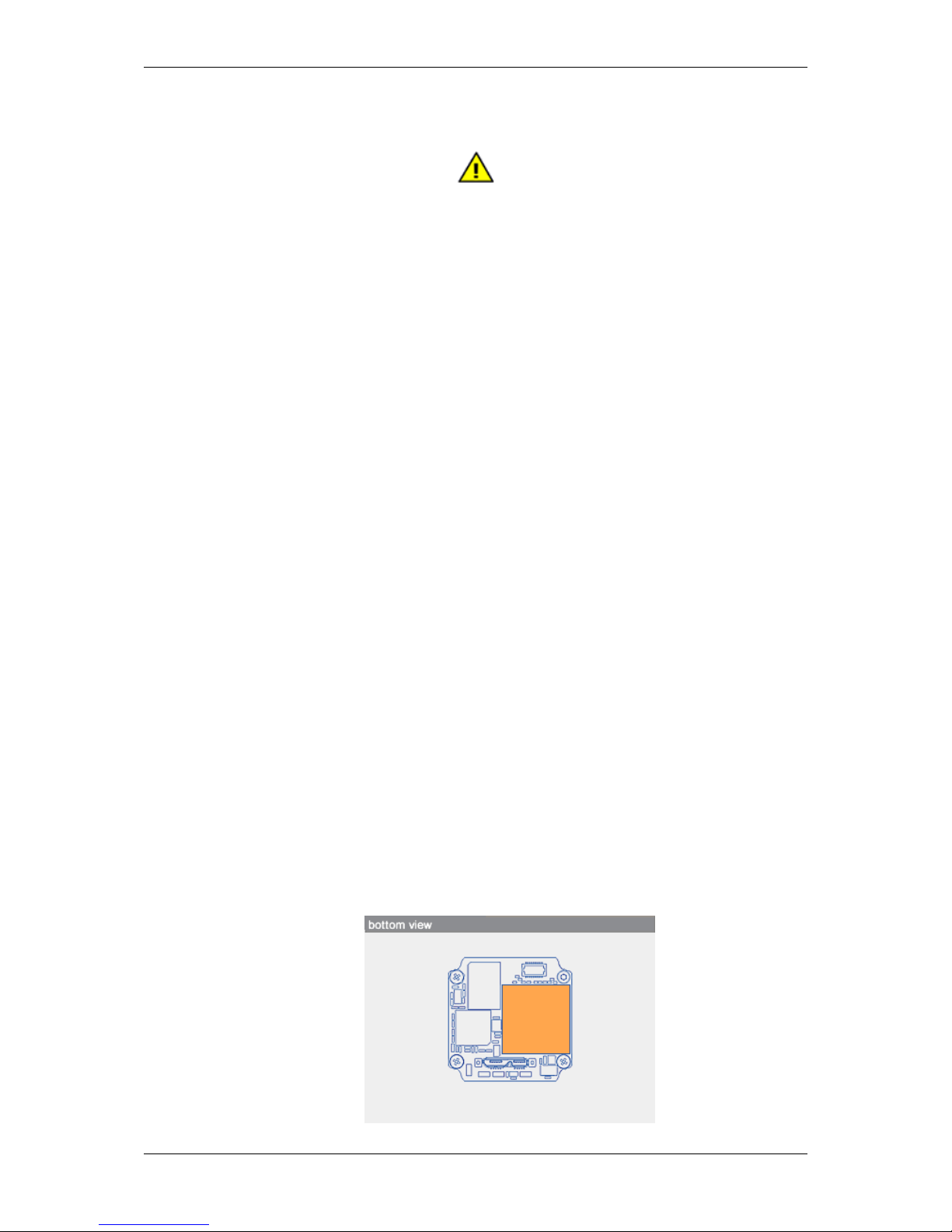
– Provide sufficient cooling because single components can reach high temperatures. Inadequate and
incorrect cooling invalidate the guarantee. For heat dissipation of the mvBlueFOX3-M2xxx-1111, we
recommend the surface of the FPGA (orange area of the following figure):
MATRIX VISION GmbH
Page 32

6.2 Operating considerations 21
Warning
The mainboard's temperature may not exceed 80°C!
• Observe that flammable objects, water or metal do not enter the camera interior. These may lead to failure or
accident.
• Do not modify the camera or use the camera with external covers removed. These may cause failure, void
any warranties and pose a safety hazard.
• Stop using the camera at the approach of electrical storm (thunder audible). Protect the camera from rain if
using it outdoors.
• In the event of abnormal functioning, switch off the camera and disconnect the power cord. Contact MATRIX
VISION.
6.2.2 Handling and cleaning
• Do not attempt to disassemble camera.
• When installing or removing a lens, take care that water or dust does not enter the inside of the camera.
6.2.3 Installing
Avoid installing or storing the camera in the following environments:
• Environments exposed to direct sunlight, rain or snow.
• Environments where combustible or corrosive gas exists.
• Excessively warm or cold environment (Operating ambient temperature: 0 to 45 °C)
• Humid or dusty environment.
• Place subjected to excessive vibration or shock.
• Environment exposed to strong electric or magnetic field.
• It is recommended to mount the camera on a thermoconducting surface such as aluminum or other metals
rather than plastic or wood.
• Please contact manufacturer or local distributor if you want to use additional enclosures for higher ingress
protection.
• Do not aim the camera lens at the sun or other very strong light sources.
6.2.4 Optimizing performance and life time
When the camera is used continuously for long time under high ambient temperature, the inside electrical parts may
deteriorate, resulting in shorter life span. Additional cooling by e.g. air convection is recommended.
6.2.5 Connectors
Confirm the power is off before connecting or disconnecting a signal cable. Grasp connectors by the body, not the
attached wires.
MATRIX VISION GmbH
Page 33

22 CONTENTS
6.2.6 Cleaning
• Use a blower or a lens brush to remove dust on the lens or the optical filter.
• Do not disassemble front flange.
• Clean case with dry soft cloth. Use neutral detergent liquid if needed; wipe the cover with dry cloth.
• Do not use benzene, thinner, alcohol, liquid cleaner or spray-type cleaner.
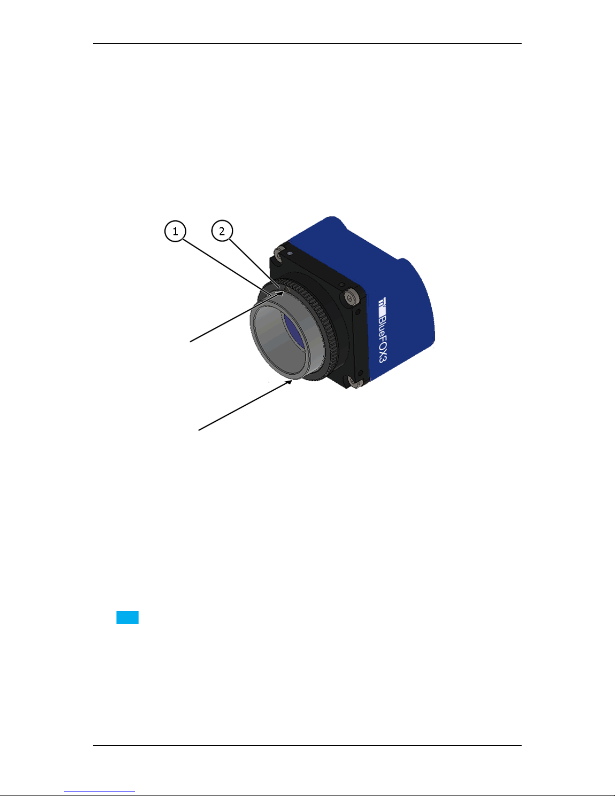
6.2.7 Adjusting the C-mount (mvBlueFOX3-2xxx-1xxx)
The mvBlueFOX3-2xxx-1xxx does not support back focus adjustment. However, with the four screw locks at the
front of the lens holder, it is possible to rotate the C-mount ring.
Warning
In combination with mvBlueFOX3-2089 and mvBlueFOX3-2124 the C-mount lens holder has to look upwards
during the adjusting. Otherwise the aperture can jump out of the guide.
• Loosen the screw locks with an Allen key (2.5 mm).
• With it, you can adjust the position of the lens, for example, to have the scale or the locking screws of the lens
at a specific position.
Figure 1: mvBlueFOX3-2xxx-1xxx Lensholder with C-mount ring (1) and screw locks (2)
Warning
Always tighten the screws in a diagonal sequence first slightly and then little by little to a torque of 0.9 Nm.
MATRIX VISION GmbH
Page 34
6.3 European Union Declaration of Conformity statement 23
6.2.8 Adjusting the C-mount (mvBlueFOX3-2xxx-2xxx)
The mvBlueFOX3-2xxx-2xxx cameras allow a precise adjustment of the back focus of the C-mount by means of a
back focus ring which is threaded into the C-mount and is secured by a lock nut ring which itself is secured by two
screws. The mechanical adjustment of the imaging device is important in order to achieve a perfect alignment with
the focal point of the lens. This adjustment is made before leaving the factory to conform to the standard of 17.526
mm (in air) and should normally not require adjustment in the field. However, if the back focal plane of your lens
does not conform to the C-mount back focus specification or if you have e.g. removed the IR-CUT filter (p.72),
renewed adjustment may be required.
Figure 2: mvBlueFOX3-2xxx-2xxx Lensholder with C-mount ring (1) and lock nut ring (2)
How to proceed:
• Loosen screws (location as shown above by arrows) of the lock nut ring with an Allen key (0.9 x 50).
• Loosen the lock nut ring.
• With the lens set to infinity or a known focus distance, set the camera to view an object located at "infinity" or
the known distance.
• Rotate the C-mount ring and lens forward or backwards on its thread until the object is in sharp focus.
Note
Be careful that the lens remains seated in the C-mount.
• Once focus is achieved, tighten the lock nut ring, then tighten the two locking screws of the lock ring without
applying excessive torque.
6.3 European Union Declaration of Conformity statement
MATRIX VISION GmbH
Page 35

24 CONTENTS
The mvBlueFOX3 is in conformity with all applicable essential requirements necessary for CE
marking. It corresponds to the EU EMC guideline 2014/30/EU based on the following harmonized
standards Electromagnetic compatibility (EMC)
• Interference emission EN 61000-6-3 / 2007
• Interference immunity EN 61000-6-2 / 2005
MATRIX VISION corresponds to the EU guideline WEEE 2002/96/EG on waste electrical and electronic equipment and is registered under WEEE-Reg.-No. DE 25244305.
RoHS All units delivered are RoHS compliant.
MATRIX VISION GmbH
Page 36

6.3 European Union Declaration of Conformity statement 25
MATRIX VISION GmbH
Page 37

26 CONTENTS
MATRIX VISION GmbH
Page 38

6.3 European Union Declaration of Conformity statement 27
MATRIX VISION GmbH
Page 39

28 CONTENTS
6.4 Legal notice
6.4.1 For customers in the U.S.A.
MATRIX VISION GmbH
Page 40

6.4 Legal notice 29
Class B
This equipment has been tested and found to comply with the limits for a Class B digital device, pursuant to Part
15 of the FCC Rules. These limits are designed to provide reasonable protection against harmful interference
when the equipment is operated in a residential environment. This equipment generates, uses, and can radiate
radio frequency energy and, if not installed and used in accordance with the instruction manual, may cause harmful
interference to radio communications. However there is no guarantee that interferences will not occur in a particular
installation. If the equipment does cause harmful interference to radio or television reception, the user is encouraged
to try to correct the interference by one or more of the following measures:
• Reorient or relocate the receiving antenna.
• Increase the distance between the equipment and the receiver.
• Use a different line outlet for the receiver.
• Consult a radio or TV technician for help.
You are cautioned that any changes or modifications not expressly approved in this manual could void your authority
to operate this equipment. The shielded interface cable recommended in this manual must be used with this
equipment in order to comply with the limits for a computing device pursuant to Subpart B of Part 15 of FCC Rules.
6.4.2 For customers in Canada
This apparatus complies with the Class B limits for radio noise emissions set out in the Radio Interference Regulations.
6.4.3 Pour utilisateurs au Canada
Cet appareil est conforme aux normes classe B pour bruits radioélectriques, spécifiées dans le Règlement sur le
brouillage radioélectrique.
MATRIX VISION GmbH
Page 41

30 CONTENTS
7 Introduction
Figure 1: mvBlueFOX3-1
The mvBlueFOX3 is a compact USB 3.0 camera which is compliant to the brand new vision standard USB3 Vision
(p. 161). The mvBlueFOX3 offers
• a wide range of CMOS sensors,
• high frame rates,
• I/Os suitable for industrial applications, and
• wide range of resolutions.
The image memory of the camera enables a high-speed-buffer mode (a.k.a. burst mode) which writes images faster
in the camera's memory as they are transferred. With this mode, image losses are a thing of the past.
The mvBlueFOX3 is ideally suited for all classical areas of machine vision and especially for applications in the
medicine and microscopy area. The hardware capabilities can be teamed with MATRIX VISION's machine vision
library mvIMPACT or any other third party libraries which are compliant to USB3 Vision.
7.1 Software concept
The mvBlueFOX3 is a USB3 Vision (p.161) compliant device, using a GenICam (p. 155) XML-file describing the
device capabilities. Within this XML-file it uses the names, units, data types etc. recommended by the SFNC (p.159)
to describe the devices features. Whenever custom features have been added to the mvBlueFOX3 firmware these
can clearly be spotted by the leading 'mv' in the features name. The device can communicate with every third party
compliant USB3 Vision (p. 161) capture driver that can interpret GenICam (p. 155) XML-files.
The following figure shows the software concept of MATRIX VISION's camera devices:
MATRIX VISION GmbH
Page 42
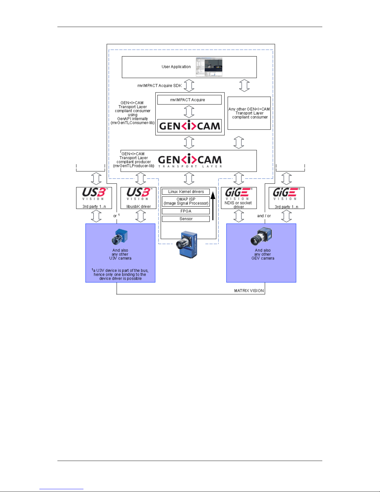
7.2 Order code nomenclatures 31
Figure 2: Software concept of mvBlueFOX3
As shown in figure 2, for the mvBlueFOX3 the mvIMPACT_Acquire (p. 157) interface is stacked on the USB3
Vision (p.161) and Genicam (p. 155) layers. The mvIMPACT_Acquire (p. 157) interface internally uses the Gen←-
ICam (p. 155) runtime libs, so that it can be considered as an user application written with the GenICam (p.155)
interface.
7.2 Order code nomenclatures
7.2.1 mvBlueFOX3
The mvBlueFOX3 nomenclature scheme is as follows:
mvBlueFOX3 - (M) A B C - (1)(2)(3)(4)
- (M): Model, add "M" for single-board model
- A: Sensor model
MATRIX VISION GmbH
Page 43

32 CONTENTS
2004: 0.4 Mpix, 728 x 544, 1/2.9", CMOS
1012b: 1.2 Mpix, 1280 x 960, 1/3", CMOS
1012d: 1.2 Mpix, 1280 x 960, 1/3", CMOS
1013: 1.3 Mpix, 1280 x 1024, 1/1.8", CMOS
1020: 2.0 Mpix, 1600 x 1200, 1/1.8", CMOS
1020a: 2.0 Mpix, 1600 x 1200, 1/1.8", CMOS
2016: 1.6 Mpix, 1456 x 1088, 1/2.9", CMOS
2024: 2.4 Mpix, 1936 x 1214, 1/1.2", CMOS
2024a: 2.4 Mpix, 1936 x 1214, 1/1.2", CMOS
1031: 3.1 Mpix, 2052 x 1536, 1/3", CMOS
2032: 3.2 Mpix, 2048 x 1536, 1/1.8", CMOS
2032a: 3.2 Mpix, 2064 x 1544, 1/1.8", CMOS
2051: 5.1 Mpix, 2464 x 2056, 2/3", CMOS
2051a: 5.1 Mpix, 2464 x 2056, 2/3", CMOS
2089: 8.9 Mpix, 4112 x 2176, 1", CMOS
2089a: 8.9 Mpix, 4112 x 2176, 1", CMOS
1100: 10 Mpix, 3856 x 2764, 1/2.35", CMOS
2124: 12.4 Mpix, 4112 x 3008, 1.1", CMOS
2124a: 12.4 Mpix, 4112 x 3008, 1.1", CMOS
- B: Sensor color
G: Gray scale
C: Color
- C: Infrared enhanced (for -1013G)
E: Infrared enhanced
- (1): Lensholder
only mvBlueFOX3-1
1: CS-mount (standard) without back focus adjustment
2: C-mount without back focus adjustment
only mvBlueFOX3-2
1: C-mount (standard) without back focus adjustment
2: C-mount with back focus adjustment
- (2): Filter
1: IR-CUT (standard)
2: Glass
3: Daylight cut
9: None
- (3): Case
1: Color blue (standard)
2: Color black, no logo
- (4): I/O
1: None (standard)
2: With I/O
7.2.2 mvBlueFOX3-M1
The mvBlueFOX3-M1 nomenclature scheme is as follows:
mvBlueFOX3-M1(A)(B)(C) - (1)(2)(3)(4)
- (A): Sensor model
012b: 1.2 Mpix, 1280 x 960, 1/3"
012d: 1.2 Mpix, 1280 x 960, 1/3"
013: 1.3 Mpix, 1280 x 1024, 1/1.8"
020: 2.0 Mpix, 1600 x 1200, 1/1.8"
020a: 2.0 Mpix, 1600 x 1200, 1/1.8"
031: 3.1 Mpix, 2052 x 1536, 1/3"
100: 10 Mpix, 3856 x 2764, 1/2.35"
- (B): Sensor color
G: Gray scale
C: Color
- (C): Infrared enhanced (for -013G)
E: Infrared enhanced
- (1): Lensholder
1: no lensholder
2: BF3-LH-SMNT 13
- (2): Filter
1: standard
- (3): Case
MATRIX VISION GmbH
Page 44

7.3 What's inside and accessories 33
1: standard
- (4): I/O
1: standard; if I/O is needed, use separate article: mvBlueFOX3-IO
7.2.3 mvBlueFOX3-M2
The mvBlueFOX3-M2 nomenclature scheme is as follows:
mvBlueFOX3-M2(A)(B) - (1)(2)(3)(4)
- (A): Sensor model
004: 0.4 Mpix, 728 x 544, 1/2.9", CMOS
016: 1.6 Mpix, 1456 x 1088, 1/2.9", CMOS
024: 2.4 Mpix, 1936 x 1214, 1/1.2", CMOS
024a: 2.4 Mpix, 1936 x 1214, 1/1.2", CMOS
032: 3.2 Mpix, 2048 x 1536, 1/1.8", CMOS
032a: 3.2 Mpix, 2064 x 1544, 1/1.8", CMOS
051: 5.1 Mpix, 2464 x 2056, 2/3", CMOS
051a: 5.1 Mpix, 2464 x 2056, 2/3", CMOS
089: 8.9 Mpix, 4112 x 2176, 1", CMOS
089a: 8.9 Mpix, 4112 x 2176, 1", CMOS
124: 12.4 Mpix, 4112 x 3008, 1.1", CMOS
124a: 12.4 Mpix, 4112 x 3008, 1.1", CMOS
- (B): Sensor color
G: Gray scale
C: Color
- (1): Lensholder
1: No lensholder
2: C-mount with adjustable backfocus (lensholder type 1 or type 1-A)
3: S-mount
4: BF3-M2-LH-SMNT-13-00
- (2):
1: IR-CUT (standard)
2: Glass
3: Daylight cut
9: No filter
- (3):
1: Standard
5: With heat sink backplate (not available with I/O)
- (4): I/O
1: None (standard)
2: With I/O
7.2.4 Ordering code samples
mvBlueFOX3-1013G
1
CMOS, 1.3 Mpix, 1280 x 1024, 1/1.8", gray scale.
mvBlueFOX3-2024C-1212 CMOS, 2.4 Mpix, 1936 x 1214, 1/1.2", color, CS-mount without back focus adjust-
ment, glass filter, etc.
mvBlueFOX3-1100G-2312 CMOS, 10 Mpix, 3856 x 2764, 1/2.35", gray scale, C-mount without back focus
adjustment, daylight cut filter, with I/O
1
: -1111 is the standard delivery variant and for this reason it is not mentioned.
7.3 What's inside and accessories
The mvBlueFOX3 is shipped without any accessories:
MATRIX VISION GmbH
Page 45

34 CONTENTS
Figure 3: mvBlueFOX3 - scope of supply
For this reason, you will need at least
• a lens (by default, the mvBlueFOX3 is shipped without lens) and
• a USB 3.0 cable
to use the mvBlueFOX3.
Note
Although maximum cable length is not specified in the USB 3.0 standard, the electrical properties of the cable
and signal quality limitations may define the practical maximum length.
There are different USB 3.0 cable qualities available on the market. If you want to use your own USB 3.0
cables, you have to ensure that the data quality and shielding of the cable is sufficient.
As a rule of thumb thin cables will only work for short distances up to max. 3m.
Better cable qualities which go alongside with thicker cable diameter will allow longer distances such as 5m or
even 8m.
We recommend to use the cables we supply to be on the safe side.
7.3.1 Accessories for the mvBlueFOX3
Part code Description
KS-MICUSB3B-A LS USB 3.0 cable lockable, length up to 5 m
KS-BCX-HR12 I/O cable, length up to 20 m
MV-ZWISCHENRING 5MM CMOUNT Spacer for C-Mount lenses
MV-Tripod Adapter BF3 1/4" tripod adapter including three suitable screws
TRIPOD ADAPT BF3-2 Tripod adapter for mvBlueFOX3-2
mvBlueFOX3-IO I/O board for mvBlueFOX3-M (mvBlueFOX3-IO) (p.56)
mvBlueFOX3-IO NC I/O board for mvBlueFOX3-M (mvBlueFOX3-IO) (p. 56) without Hi-
rose connector
MATRIX VISION GmbH
Page 46

8 Quickstart 35
8 Quickstart
8.1 Driver concept
The driver supplied with the MATRIX VISION product represents the port between the programmer and the
hardware. The driver concept of MATRIX VISION provides a standardized programming interface to all image
processing products (excluding mvBlueLYNX) made by MATRIX VISION GmbH.
The advantage of this concept for the programmer is that a developed application runs without the need for any
major modifications to the various image processing products made by MATRIX VISION GmbH. You can also
incorporate new driver versions, which are available for download free of charge on our website: http://www.←-
matrix-vision.com.
The following diagram shows a schematic structure of the driver concept:
Figure 1: Driver concept
MATRIX VISION GmbH
Page 47

36 CONTENTS
• 1 Part of any mvIMPACT Acquire driver installation package (Windows).
• 2 Separately available for 32 bit and 64 bit. Requires at least one installed driver package.
• 3 See 2, but requires an installed version of the mvBlueFOX driver.
• 4 Part of the NeuroCheck installer but requires at least one installed frame grabber driver.
• 5 Part of the mvIMPACT SDK installation. However, new designs should use the .NET libs that are now part
of mvIMPACT Acquire ("mv.impact.acquire.dll"). The namespace "mv.impact.acquire" of
"mv.impact.acquire.dll" provides a more natural and more efficient access to the same features
as contained in the namespace "mvIMPACT_NET.acquire" of "mvIMPACT_NET.dll", which is why
the latter one should only be used for backward compatibility but NOT when developing a new application.
• 6 Part of Micro-Manager.
8.1.1 NeuroCheck support
A couple of devices are supported by NeuroCheck. However between NeuroCheck 5.x and NeuroCheck 6.x there
has been a breaking change in the internal interfaces. Therefore also the list of supported devices differs from one
version to another and some additional libraries might be required.
For NeuroCheck 5.x the following devices are supported:
Device Additional software needed
mvTITAN-G1 mvSDK driver for mvTITAN/mvGAMMA devices
mvTITAN-CL mvSDK driver for mvTITAN/mvGAMMA devices
mvGAMMA-CL mvSDK driver for mvTITAN/mvGAMMA devices
mvBlueFOX mvIMPACT Acquire driver for mvBlueFOX devices, "NCUSBmvBF.dll"
For NeuroCheck 6.0 the following devices are supported:
Device Additional software needed
mvTITAN-G1 mvIMPACT Acquire driver for mvTITAN/mvGAMMA de-
vices
mvTITAN-CL mvIMPACT Acquire driver for mvTITAN/mvGAMMA de-
vices
mvGAMMA-CL mvIMPACT Acquire driver for mvTITAN/mvGAMMA de-
vices
mvHYPERION-CLb mvIMPACT Acquire driver for mvHYPERION devices
Every other mvIMPACT Acquire compliant device mvIMPACT Acquire driver for the corresponding device
family, "mv.impact.acquire.NeuroCheck6.←-
dll" (comes with the driver package, but the driver
package must be installed AFTER installing NeuroCheck 6
For NeuroCheck 6.1 the following devices are supported:
Device Additional software needed
mvTITAN-G1 mvIMPACT Acquire driver for mvTITAN/mvGAMMA de-
vices
mvTITAN-CL mvIMPACT Acquire driver for mvTITAN/mvGAMMA de-
vices
mvGAMMA-CL mvIMPACT Acquire driver for mvTITAN/mvGAMMA de-
vices
mvHYPERION-CLb mvIMPACT Acquire driver for mvHYPERION devices
MATRIX VISION GmbH
Page 48

8.1 Driver concept 37
Every other mvIMPACT Acquire compliant device mvIMPACT Acquire driver for the corresponding device
family, "mv.impact.acquire.NeuroCheck6_←-
1.dll" (comes with the driver package, but the driver
package must be installed AFTER installing NeuroCheck
6.1
8.1.2 VisionPro support
Every mvIMPACT Acquire driver package under Windows comes with an adapter to VisionPro from Cognex. The
installation order does not matter. After the driver package and VisionPro has been installed, the next time VisionPro
is started it will allow selecting the mvIMPACT Acquire device. No additional steps are needed.
MATRIX VISION devices that also comply with the GigE Vision standard don't need any software at all, but can also
use VisionPro's built-in GigE Vision support.
8.1.3 HALCON support
HALCON comes with built-in support for mvIMPACT Acquire compliant devices, so once a device driver has been
installed for the mvIMPACT Acquire device, it can also be operated from a HALCON environment using the corresponding acquisition interface. No additional steps are needed.
MATRIX VISION devices that also comply with the GigE Vision standard don't need any software at all, but can also
use HALCON's built-in GigE Vision support.
As some mvIMPACT Acquire device driver packages also come with a GenTL compliant interface, these can also
be operated through HALCON's built-in GenTL acquisition interface.
8.1.4 LabVIEW support
Every mvIMPACT Acquire compliant device can be operated under LabVIEW through an additional set of VIs which
is shipped by MATRIX VISION as a separate installation ("mvLabVIEW Acquire").
MATRIX VISION devices that also comply with the GigE Vision or USB3 Vision standard don't need any additional
software at all, but can also be operated through LabVIEW's GigE Vision or USB3 Vision driver packages.
8.1.5 DirectShow support
Every mvIMPACT Acquire compliant device driver package comes with an interface to DirectShow. In order to be
usable from a DirectShow compliant application, devices must first be registered for DirectShow support. How to
this is explained here (p.134).
8.1.6 Micro-Manager support
Every mvIMPACT Acquire compliant device can be operated under https://micro-manager.org when
using mvIMPACT Acquire 2.18.0 or later and at least Micro-Manager 1.4.23 build AFTER 15.12.2016. The
adapter needed is part of the Micro-Manager release. Additional information can be found here: https←-
://micro-manager.org/wiki/MatrixVision.
MATRIX VISION GmbH
Page 49

38 CONTENTS
8.2 Windows
8.2.1 System requirements
Currently supported Windows versions are:
• Microsoft Windows 7 (32-bit, 64-bit)
• Microsoft Windows 8.1 (32-bit, 64-bit)
• Microsoft Windows 10 (32-bit, 64-bit)
Other Windows version can be used at the user's own risk.
Note
Since mvIMPACT Acquire version 2.8.0 it could be possible that you have to update your Windows installer at
least using Windows XP. The necessary packages are available from Microsoft's website: http://www.←-
microsoft.com/en-US/download/details.aspx?id=8483
All necessary drivers for Windows are contained in the standard mvIMPACT CD-ROM or DVD-ROM. For newer
driver versions we recommend to visit the MATRIX VISION website at www.matrix-vision.de, section "Products
-> Cameras -> your interface -> your product -> Downloads".
8.2.1.1 Hardware
MATRIX VISION testet successfully several USB 3.0 extension cards or adapters for PCs and Notebooks. Please
have a look here for a current listing:
See also
http://www.matrix-vision.com/faq-mvbluefox-en.html?show=824
8.2.2 Installing the mvGenTL-Acquire driver
By double clicking on
• mvGenTL_Acquire-x86-n.n.n.msi (for 32-bit systems) or
• mvGenTL_Acquire-x86_64-n.n.n.msi (for 64-bit systems), the installer will start automatically:
MATRIX VISION GmbH
Page 50

8.2 Windows 39
Figure 2: Driver installation - start window
• Now, follow the instructions of installation program
Figure 3: Driver installation - select installation folder
• and use default settings:
MATRIX VISION GmbH
Page 51

40 CONTENTS
Figure 4: Driver installation - select features
• The installation will start and copies the data. At the end, MATRIX VISION's USB3 Vision (p.161) capture
filter driver will be installed. A "Windows Security" dialog will appear.
• Click on Install (This however requires the system to be rebooted, thus the installer will ask the user to reboot
the system.).
Figure 5: Driver installation - Windows Security message
• After the system has been restarted, the filter driver installation will start automatically. Click "Ok".
• Afterwards, please ignore the compatibility testing of Windows and click on "Continue anyway" twice.
• After the installation of the USB3 Vision (p. 161) capture filter driver you will see following dialog. Click "Ok".
• Now, the driver installation will be finished.
You will find all tools like
MATRIX VISION GmbH
Page 52

8.2 Windows 41
• wxPropView (p.74) and
• mvDeviceConfigure (p.100)
either on desktop as single icons or in Windows menu under "MATRIX VISION -> mvIMPACT Acquire".
Note
You can ignore the other tools mvIPConfigure and mvGigEConfigure, because they are only necessary in
combination with GigE Vision devices like the mvBlueCOUGAR-X.
During installation, you can select the features you want to install. It is also possible to select "Firmware updates":
In this case, the installer will copy the update file "mvBlueFOX3_Update.mvu" into the MATRIX VISION driver
installation directory:
"[Path: e.g. C:\Program Files\]MATRIX VISION\mvIMPACT acquire\FirmwareUpdates\mvBlueFOX3\
Afterwards, you can use mvDeviceConfigure (p.100) to update the firmware. The latest firmware image is available
on the web - please check for updates. The current firmware version can be read out using wxPropView (p. 74)
(Device section on top) or via
cat /etc/FIRMWARE
when working locally.
8.2.3 Connecting the camera
After the driver installation you have to connect the mvBlueFOX3 using a USB 3.0 cable.
You can check connection by using tool mvDeviceConfigure (p. 100). In the program's window, your camera should
be listed:
Figure 6: Connected mvBlueFOX3
Afterwards, you can How to see the first image (p. 79) using wxPropView (p. 74).
MATRIX VISION GmbH
Page 53

42 CONTENTS
8.3 Linux
Please check our website for the availability of the Linux driver.
8.3.1 System requirements
• Kernel 3.5.x or greater
Note
Linux kernels prior to 3.5.x do not inherently support USB 3.0!
In case the target system runs an older Linux kernel, it is absolutely necessary to update the kernel to at least
version 3.5.0 . Please refer to the documentation of your Linux distribution for information on how to update your
system's Linux kernel.
Following Kernels have been tested and verified by MATRIX VISION for seamless USB3 operation:
• Kernel 3.8.0
• Kernel 3.11.0
• Kernel 3.14.0
Before installation on a Linux system (e.g. Ubuntu 12.04), the system has to provide at least following packages:
• libwxbase3.0-0
• libwxbase3.0-dev
• libwxgtk3.0-0
• libwxgtk3.0-dev
• wx3.0-headers
• build-essential (meta package)
• libgtk2.0-dev
• gcc 4.1 environment or newer
8.3.1.1 Hardware
MATRIX VISION testet successfully several USB 3.0 extension cards or adapters for PCs and Notebooks. Please
have a look here for a current listing:
See also
http://www.matrix-vision.com/faq-mvbluefox-en.html?show=824
MATRIX VISION GmbH
Page 54

8.3 Linux 43
8.3.2 Installing the mvGenTL-Acquire driver
To use the mvBlueFOX3 camera within Linux (grab images from it and change its settings), a driver is needed,
consisting of several libraries and several configuration files. These files are required during run time.
To develop applications that can use the mvBlueFOX3 camera, a source tree is needed, containing header files,
makefiles, samples, and a few libraries. These files are required at compile time.
Both file collections are distributed in a single package:
mvGenTL_Acquire-x86-n.n.n.tgz
• Please start a console and change into a directory e.g. /home/username/workspace :
cd /home/username/workspace
• Copy the install script and the hardware driver to the workspace directory (e.g. from a driver CD or from the
website):
~/workspace$ cp /media/cdrom/drv/Linux/install_mvGenTL_Acquire.sh /media/cdrom/drv/Linux/mvGenTL_Acquire-
x86-2.3.2.tgz .
• Run the install script:
~/workspace$ ./install_mvGenTL_Acquire.sh
Note
The install script has to be executable. So please check the rights of the file. During installation, the script will
ask, if it should build all tools and samples.
You may need to enable the execute flag with
chmod a+x install_mvGenTL_Acquire.sh
The installation script checks the different packages and installs them with the respective standard packages manager (e.g. apt-get) if necessary.
Note
The installation script (install_mvGenTL_Acquire.sh) and the archive (mvGenTL_Acquire-x86-n.←-
n.n.tgz) must reside in the same directory. Nothing is written to this directory during script execution, so
no write access to the directory is needed in order to execute the script.
You need Internet access in case one or more of the packages on which the GenICam (p. 155) libs depend are
not yet installed on your system. In this case, the script will install these packages, and for that, Internet access is
required.
The script takes two arguments, both of which are optional:
• target directory name
• version
The target directory name specifies where to place the driver. If the directory does not yet exist, it will be created.
The path can be either absolute or relative; i.e. the name may but need not start with / .
MATRIX VISION GmbH
Page 55

44 CONTENTS
Note
This directory is only used for the files that are run time required.
The files required at compile time are always installed in
$HOME/mvimpact-acquire-n.n.n
. The script also creates a convenient softlink to this directory:
mvimpact-acquire -> mvIMPACT_acquire-2.6.0
If this argument is not specified, the driver will be placed in the default directory /opt .
The version argument is entirely optional. If no version is specified, the most recent
mvGenTL_Acquire-x86-n.n.n.tgz
found in the current directory will be installed.
8.3.3 Connecting the camera
After the driver installation you have to connect the mvBlueFOX3 using a USB 3.0 cable.
You can check connection by using tool mvDeviceConfigure (p. 100). In the program's window, your camera should
be listed.
Afterwards, you can start wxPropView (p. 74) to configure the mvBlueFOX3.
Since driver version 2.11.3, starting wxPropView (p. 74) the first time, the Quick Setup Wizard (p. 74) , a
tiny and powerful configuration tool, will be started.
8.3.4 Defining udev rules
Most Linux system nowadays use the udev device manager, which is responsible for dynamically managing the
/dev tree. In order to be able to use the MATRIX VISION mvBlueFOX3 USB3 Vision (p.161) camera as non-root
user, a special set of rules has to be handed to the udev device manager.
On older systems this could be done by directly editing the contents of a "/etc/udev/rules" file, however
nowadays a "/etc/udev/rules.d" directory exists, which may contain several different files, each defining
the behavior of a system device.
In the specific case of the mvBlueFOX3 camera, if the camera has been installed through the respective installation
script install_mvGenTL_Acquire.sh , a suitable set of rules has been installed automatically. However if
for some reason the rules have to be created manually it should be done according to the following steps:
1. Create a file in the "/etc/udev/rules.d" directory with name 52-U3V.rules .
2. Type the following content into the file:
MATRIX VISION GmbH
Page 56

8.3 Linux 45
SUBSYSTEM!="usb|usb_device|plugdev", GOTO="u3v_rules_end"
ACTION!="add", GOTO="u3v_rules_end"
ATTRS{bDeviceClass}=="ef", ATTRS{bDeviceSubClass}=="02", ATTRS{bDeviceProtocol}=="01", ENV{
ID_USB_INTERFACES}=="*:ef0500:*", MODE="0664", GROUP="plugdev"
LABEL="u3v_rules_end"
3. OPTIONAL: Create another file in the "/etc/udev/rules.d" directory with name 52-mvbf3.rules
. This step is only necessary if a mvBlueFOX3 in the "mvbootloader" state should be recognised by the
system.
4. OPTIONAL: Type the following content into the file:
SUBSYSTEM!="usb|usb_device|plugdev", GOTO="mvbf_rules_end"
ACTION!="add", GOTO="mvbf_rules_end"
ATTRS{idVendor}=="164c", ATTRS{idProduct}=="5531", MODE="0664", GROUP="plugdev"
LABEL="mvbf_rules_end"
This step is only necessary if a mvBlueFOX3 in the "mvbootloader" state should be recognised by the system.
5. Save the file(s) and exit your editor
Note
The above 52-U3V.rules file provides the necessary access privileges not only for mvBlueFOX cameras,
but also for U3V-compliant cameras of any other vendor.
As soon as this file is into place, each time the camera is plugged to the system it acquires the set of rights that
allows the user to use it without having root privileges.
8.3.5 Optimizing USB performance
On most contemporary Linux systems, support for USB 3.0 functionality has moved from separate kernel modules to
the kernel itself (usbcore). On such systems, the kernel memory which is allocated for use with USB is predefined
and set to a relatively small value (e.g. 16 MB on a typical 32-bit Ubuntu 12.04 System). This value is usually
enough for reading from an external HDD or similar applications, but in the case of machine vision applications, with
Megapixel sensors and ultra-fast transfer speeds it is way too low.
Note
You may inquire the value (in Megabytes) on your system by typing:
cat /sys/module/usbcore/parameters/usbfs_memory_mb .
It is highly recommended to increase this value to at least 256 MB or even more depending on your application
(number of cameras, number of request objects per camera etc.). For example, a 5 Mpix camera, capturing RGB
data with a default request count of 10, needs about 5M ∗ 3 ∗ 10 ∼= 150MB of the usbfs memory. Always bear in
mind though, that mvIMPACT Acquire is probably not the only system component using usbcore memory, so you
should always reserve several MB more than the number you get from the above calculation. As a general rule of
thumb, for a single-camera application with a default request setting of 10, a value of 256 MB should be adequate.
To change the value of the usbfs_memory_mb system parameter, one has to invoke the kernel at boot time
with an argument that sets the parameter to the desired value. Trying to modify this parameter after the system
has booted (e.g. with modprobe ), will have no effect since usbcore is a system module integrated in the Linux
kernel, and not a separate kernel module which can be loaded and unloaded on demand.
Passing parameters to the kernel at boot time is usually done by typing: systemModuleName.←-
parameter=value . In our case this would be:
MATRIX VISION GmbH
Page 57

46 CONTENTS
usbcore.usbfs_memory_mb=256
How this can be done depends on the system bootloader. For systems using the GRUB2 bootloader the
"/etc/default/grub" ( or in some distributions "/etc/default/grub/c.cfg" ) file has to be modi-
fied.
Warning
Always modify configuration files with extreme caution, since the slightest syntax error may render the file
invalid, or even the computer not bootable!
After opening this file, the GRUB_CMDLINE_LINUX_DEFAULT entry must be located. It usually has the following
value:
GRUB_CMDLINE_LINUX_DEFAULT="quiet splash"
In order to invoke the Kernel with the usbfs_memory_mb parameter, it should be modified like:
GRUB_CMDLINE_LINUX_DEFAULT="quiet splash usbcore.usbfs_memory_mb=256"
As a final step, GRUB has to be updated by executing the update-grub script:
sudo update-grub
If all went well, after rebooting the system, the kernel will utilize the requested amount of memory for the usbcore
subsystem.
Note
On systems with GRUB Legacy support the bootloader settings are controlled by other files ( e.←-
g. "/boot/grub/menu/c.lst" etc.). In this case it is recommended to upgrade your bootloader to
GRUB2 :
sudo apt-get install grub2
If, for some reason, this is not an option, then the menu.lst itself could be directly modified as an absolutely
last resort. Always keep in mind that it is strongly recommended not to tamper directly with files in the
/boot/grub directory! The smallest typing error can render the system not bootable!
8.3.5.1 For Odroid-XU3 Users
To adapt the usbfs buffer size using Odroid-XU3, please follow these steps:
1. Open the file /media/boot/boot.ini as root.
2. Add or adapt the string "usbcore.usbfs_memory_mb=256" at the end of the boot arguments using a blank:
setenv bootargs "... usbcore.usbfs_memory_mb=256"
3. Save the file.
4. Reboot the Odroid-XU3 board.
MATRIX VISION GmbH
Page 58

8.3 Linux 47
8.3.5.2 For Odroid-U2 / -U3 Users
Although Odroid-U2 and Odroid-U3 do not have a USB 3.0 port, you can use the mvBlueFOX3 cameras with the
USB 2.0. Jusst adapt the following settings:
1. Locate the file boot.scr (by default: /media/boot).
2. Export the strings from the file:
strings boot.scr >> boot.txt
3. Add or adapt the string "usbcore.usbfs_memory_mb=256" at the end of the boot arguments using a blank:
setenv bootargs "... usbcore.usbfs_memory_mb=256"
4. Create a new boot.scr from the modified boot.txt.
mkimage -A arm -T script -C none -n "boot.scr for ODROID" -d boot.txt boot.scr
5. Reboot the board.
Note
The net bandwidth of USB 2.0 remains the same of course (30 MB/s).
8.3.5.3 For Raspberry Pi Users
Like Odroid-U2 and Odroid-U3, the Raspberry Pi only features a USB 2.0 port. However, it is also possible to use
the mvBlueFOX3 with this port, just follow these steps:
1. Open the file /boot/firmware/cmdline.txt as root.
2. Add or adapt the string "usbcore.usbfs_memory_mb=256" at the end of the boot arguments using a blank:
setenv bootargs "... usbcore.usbfs_memory_mb=256"
3. Save the file.
4. Reboot the Raspberry Pi board.
Note
Likewise, the net bandwidth of USB 2.0 remains the same of course (30 MB/s).
MATRIX VISION GmbH
Page 59

48 CONTENTS
8.3.5.4 For NVIDIA Tegra TK1 Users
To use the camera following adaptions are necessary in the standard configuration of the NVIDIA Tegra TK1 board:
1. Update the software to version 21.3. Please follow this descripion.
2. Afterwards, you have to adapt the boot parameters in /boot/extlinux/extlinux.conf:
(a) Change "usb_port_owner_info=0" to "usb_port_owner_info=2" (this will change the USB port behavior
from USB 2.0 to USB 3.0).
(b) Set "usbcore.autosuspend=-1" (power save mode is off now).
(c) Set "usbcore.usbfs_memory_mb=256" (this will increase the buffer of the USB bus)
3. Install the mvGenTL_Acquire driver.
Now, the camera should work. If you could not find the mvBlueFOX3 driver, you would add the current user to the
plugdev group:
sudo usermod -a -G plugdev ubuntu
8.4 Relationship between driver, firmware, FPGA file and user settings
To operate a GenICam (p. 155) based device like mvBlueFOX3 apart from the physical hardware itself 2 pieces of
software are needed:
• A firmware running on the device. This firmware consists of
– A GenICam (p. 155) compliant XML file exposing the features in a generic and standard compliant way
– A FPGA file
– The actual micro-code making the device operational
• A device driver (this is the mvGenTLConsumer.dll and the mvGenTLProducer.cti on Windows
and the libmvGenTLConsumer.so and the libmvGenTLProducer.so on Linux when using mv←-
IMPACT Acquire, but can be any other USB3 Vision (p.161) compliant driver package from a third party
vendor) running of the host system (provides control over the device from an application running on the host
system).
The physical GenICam (p. 155) compliant device has a firmware programmed into the device's non-volatile memory,
thus allowing the device to boot to a fully functional state without the need of any additional software running on
the host. The firmware version that will be used when operating the device does NOT depend on the driver version
that is used to communicate with the device. This will allow any piece of compliant third party software to operate
the device without the need to have special knowledge about the firmware structure. This shall be illustrated by the
following figure:
Figure 7: The firmware is not a part of the device driver
MATRIX VISION GmbH
Page 60

8.4 Relationship between driver, firmware, FPGA file and user settings 49
Note
As it can be seen in the image the firmware file is NOT part of the device driver but comes as a separate
archive. It is important to notice that a firmware file that may be present on the host system will not be used
automatically but only when the user or an application explicitly updates the firmware on the device and will
only become active after power-cycling the device.
The name of the firmware update archive (∗ in the figure above) is:
• mvBlueFOX3_Update.mvu
Only during a firmware update the firmware file that has been selected from the file system of the host system will
be downloaded permanently into the device's non-volatile memory.
Warning
Each firmware archive might contain more than one specific firmware version per device thus in order to select
the one that is appropriate for the device appropriate tools such as mvDeviceConfigure (p. 100) should be
used.
So assume a device with a certain firmware version is connected to a host system.
During an explicit firmware update, the firmware file will be downloaded onto the device. In order to become active
the device must be power-cycled:
Figure 8: Firmware file will be downloaded during an firmware update...
This can either be done by unplugging the device and then by plugging it back in or (for devices supporting this
feature) by resetting/rebooting the device by a certain software command (DeviceControl/DeviceReset). When
using mvDeviceConfigure (p. 100) to update devices the latter mechanism will be used by the tool thus it is NOT
necessary to unplug the device.
When the device has completed rebooting the new firmware version will become active:
MATRIX VISION GmbH
Page 61

50 CONTENTS
Figure 9: ... after repowering the device it will be active
• The current firmware version of the device can be obtained either by using one of the applications which are
part of the SDK such as mvDeviceConfigure (p. 100) or by reading the value of the property Device/←-
FirmwareVersion or DeviceControl/DeviceFirmwareVersion using the API
• The current FPGA file version used by the device can be obtained by reading the value of the property
DeviceControl/mvDeviceFPGAVersion
Note
The FPGA file is a part of the firmware and cannot be updated independently thus reading it's version just
provides some additional information.
Using wxPropView (p.74) the same information is available as indicated by the following figure:
Figure 10: wxPropView - FPGA and Firmware version numbers
Apart from the device driver and firmware relationship there are certain places where a device configuration can be
stored when dealing with GenICam (p. 155) compliant devices:
• There may be User Sets which are stored in the device's non-volatile memory. User Sets contain all the
features, which affect the device's behaviour such as transfer pixel format, exposure time etc. User Sets are
bound to major GenICam (p. 155) XML file releases, thus these settings will be lost whenever a firmware
contains a different major version of a devices GenICam (p. 155) XML file
MATRIX VISION GmbH
Page 62

8.5 Settings behaviour during startup 51
• mvIMPACT Acquire settings which contain the state of all the features also stored in a User Set as well as
other features added by the device driver. These settings will be stored on the host system either as a XML
file or (under Windows only) in the Registry
Both methods can be used to pre-configure a device. Using the first method, the state of the features will travel with
the physical device, using the mvIMPACT Acquire settings, feature states can be copied from host to host as a file.
8.5 Settings behaviour during startup
Settings contain all the parameters that are needed to prepare and program the device for the image capture. Every
image can be captured with completely different set of parameters. In almost every case, these parameters are
accessible via a property offered by the device driver. A setting e.g. might contain
• The gain to be applied to the analog to digital conversion process for analog video sources or
• The AOI to be captured from the incoming image data.
So for the user a setting is the one an only place where all the necessary modifications can be applied to achieve
the desired form of data acquisition. For GenICam interface layouts all device properties modified during a continuous acquisition will have immediate impact on the next frame transmitted by the device thus here when a precise
moment to change settings is needed, continuous acquisition must be stopped and then restarted after modifying
the features.
Now, whenever a device is opened, the driver will execute following procedure:
Figure 11 : wxPropView - Device setting start procedure
MATRIX VISION GmbH
Page 63

52 CONTENTS
• Please note that each setting location step in the figure from above internally contains two search steps. First
the framework will try to locate a setting with user scope and if this can't be located, the same setting will be
searched with global (system-wide) scope. Under Windows® this e.g. will access either the HKEY_CURR←-
ENT_USER or (in the second step) the HKEY_LOCAL_MACHINE branch in the Registry.
• Whenever storing a product specific setting, the device specific setting of the device used for storing will be
deleted (if existing). So when the user is currently working with a device 'VD000001' belonging to the product
group 'VirtualDevice' and there is a setting exclusively for this device storing a product specific setting now will
automatically delete the setting for 'VD000001'. Otherwise a product specific setting would never be loaded
as a device specific setting will always be found first.
• The very same thing will also happen when opening a device from any other application! wxPropView (p. 74)
does not behave in a special way but only acts as an arbitrary user application.
• Whenever storing a device family specific setting, the device specific or product specific setting of the device
used for storing will be deleted (if existing). See above to find out why.
• Under Windows® the driver will not look for a matching XML file during start-up automatically as the native
storage location for settings is the Windows® Registry. This must be loaded explicitly by the user by using
the appropriate API function offered by the SDK. However, under Linux XML files are the only setting formats
understood by the driver framework thus here the driver will also look for them at start-up. The device specific
setting will be an XML file with the serial number of the device as the file name, the product specific setting
will be an XML file with the product string as the filename, the device family specific setting will be an XML
file with the device family name as the file name. All other XML files containing settings will be ignored!
• Only the data contained in the lists displayed as
– "Image Setting",
– "Digital I/O", and
– "Device Specific Data" under wxPropView (p. 74) will be stored in these settings!
• Restoring of settings previously stored works in a similar way. After a device has been opened the settings
will be loaded automatically as described above.
• A detailed description of the individual properties offered by a device will not be provided here but can be
found in the C++ API reference, where descriptions for all properties relevant for the user (grouped together in
classes sorted by topic) can be found. As wxPropView (p. 74) doesn't introduce new functionality but simply
evaluates the list of features offered by the device driver and lists them any modification made using the GUI
controls just calls the underlying function needed to write to the selected component. wxPropView (p. 74)
also doesn't know about the type of component or e.g. the list of allowed values for a property. This again is
information delivered by the driver and therefore can be queried by the user as well without the need to have
special inside information. One version of the tool will always be delivered in source so it can be used as a
reference to find out how to get the desired information from the device driver.
MATRIX VISION GmbH
Page 64

9.1 Dimensions 53
9 Technical data
9.1 Dimensions
9.1.1 Standard model
Figure 1: mvBlueFOX3 -xx1x dimensions and connectors
mvBlueFOX3
Size of body (w x h x l) 39 x 39 x 24 mm
Lens protrusion C-Mount CS-Mount
X 12.5 mm 7.5 mm
9.1.1.1 Mounting holes
On the bottomside, the mvBlueFOX3 provides integrated tripod mounting holes.
Figure 2: mvBlueFOX3 mounting holes
MATRIX VISION GmbH
Page 65

54 CONTENTS
Figure 3: Dimensional drawing of tripod adapter
9.1.2 Standard model -2xxx
9.1.2.1 Option -1xxx (lensholder without back focus adjustment)
Figure 4: mvBlueFOX3-2xxx-1xxx dimensions and connectors
mvBlueFOX3-2xxx-1xxx
Size of body (w x h x l) 40 x 40 x 50.9 mm
Lens protrusion
X 10.7 mm with 1" lenses
C-Mount CS-Mount
Z 17.526 mm (in air) 12.5 mm (in air)
9.1.2.1.1 Mounting holes
The mvBlueFOX3-2xxx-1xxx provides integrated mounting holes.
MATRIX VISION GmbH
Page 66

9.1 Dimensions 55
Figure 5: mvBlueFOX3-2xxx-1xxx mounting holes
9.1.2.2 Option -2xxx (lensholder with back focus adjustment)
Figure 6: mvBlueFOX3-2xxx-2xxx dimensions and connectors
mvBlueFOX3-2xxx-2xxx
Size of body (w x h x l) 39.8 x 39.8 x 37.7 mm
Lens protrusion C-Mount CS-Mount
X 8 mm 6 mm
C-Mount CS-Mount
W approx. 15 mm (C-mount) approx. 10 mm (CS-mount)
Z 17.526 mm (in air) 12.5 mm (in air)
9.1.2.2.1 Mounting holes
The mvBlueFOX3-2xxx-2xxx provides integrated mounting holes.
MATRIX VISION GmbH
Page 67

56 CONTENTS
Figure 7: mvBlueFOX3-2xxx-2xxx mounting holes
9.1.3 Model without housing (-M1)
Warning
In combination with the connectors, the mechanical stress needs to be limited.
Figure 8: mvBlueFOX3-M dimensions and connectors
9.1.3.1 I/O board for mvBlueFOX3-M (mvBlueFOX3-IO)
Figure 9: mvBlueFOX3-M dimensions of additional I/O board
The following figure shows, how the additional I/O board gets connected correctly.
MATRIX VISION GmbH
Page 68

9.1 Dimensions 57
Warning
Since the connector of the I/O board will also fit upside down, you have to be careful while connecting.
Otherwise you can destroy the camera and / or the I/O board. As show in the figure, if the I/O board was
connected correctly, you can bend the I/O board on the back of the sensor board. Then the I/O board connector
will point to the opposite direction as the sensor.
Figure 10: mvBlueFOX3-M connected I/O board
The pinning of the mvBlueFOX3-I/O is described in the chapter Circular connector male (Power / Digital I/O)
(p. 59).
Note
There is also a version of the I/O board without connector as "mvBlueFOX3-IO NC" (NC = not connected).
The pinning is provided in the figure:
Figure 11: mvBlueFOX3-M dimensions of additional I/O board without connector.
MATRIX VISION GmbH
Page 69

58 CONTENTS
9.1.4 Model without housing (-M2)
Warning
In combination with the connectors, the mechanical stress needs to be limited.
Figure 12: mvBlueFOX3-M2xxx-1xx2 dimensions and connectors
9.1.4.1 S-mount lensholder and heat sink backplate option (-495x)
The heat sink backplate is connected to the GND potential of the camera's power. The connection itself takes place
via the fixing points. Both, the mounting holes on the lensholder as well as the mounting holes at the heat sink plate
can be used to mount the camera.
Figure 13: mvBlueFOX3-M2xxx-495x dimensions and connectors
Warning
Please pay attention to the Important safety notes (p. 20) when operating the mvBlueFOX3-M2 without the
heat sink backplate.
MATRIX VISION GmbH
Page 70

9.2 Camera interfaces 59
9.2 Camera interfaces
9.2.1 Circular connector male (Power / Digital I/O)
Figure 14: 12-pin (male; top view), digital I/O, power
Pin. mvBlueFOX3-1xxx |
Signal
mvBlueFOX3-2xxx |
Signal
Line in wxPropView Cable KS-BCX-HR12
color scheme
1 GND (for VDC) black
2 not connected, leave
open
12V - 24V brown
3 Opto DigOut3 Line3 red
4 Opto DigIn0 Line4 orange
5 Opto DigOut2 Line2 yellow
6 Opto DigOut0 Line0 green
7 IN_COMMON (DigIn GND) blue
8 RS232 RX violet
9 RS232 TX gray
10 OUT_V+ white
11 Opto DigIn1 Line5 white-black
12 Opto DigOut1 Line1 white-brown
Main connector shield Main connector shield Main shield
Connector (camera side): SAMWOO SNH-10-12 (RPCB) or equivalent
Plug (matching cable plug): Hirose HR10A-10P-12S (01) or equivalent
Note
RS232 is not implemented in the firmware.
9.2.1.1 Pinning of KS-BCX-HR12
Pin. CON 1 mvBlueFOX3-1xxx | Signal CON 1 mvBlueFOX3-2xxx | Signal CON 2 cutted cable | Color
1 GND (for VDC) black
2 not connected VIN+12V to +24V brown
3 DigOut3 (wxPropView (p.74) numbering: line3) red
MATRIX VISION GmbH
Page 71

60 CONTENTS
4 Opto DigIn0 (line4) orange
5 DigOut2 (line2) yellow
6 DigOut0 (line0) green
7 Opto DigIn GND blue
8 RS232_RX violet
9 RS232_TX gray
10 +OUT_V+ white
11 Opto DigIn1 (line5) white-black
12 Opto DigOut1 (line1) white-brown
Main connector shield main shield
Color assignment following international code for UL wiring.
9.2.1.2 Power Supply
The mvBlueFOX3 is bus powered. Anyway, it is possible to power the mvBlueFOX3-2 externally with following
specs:
• Input voltage range:
– 12 .. 24V DC (typical)
– min. 10V
– max. 30V
• The power supply is protected against
– burst (EN 61000-4-4)
– surge (EN 61000-4-5) and
– polarity inversion
• internal short circiuit protection by 1.5A slow blow fuse
The USB power cannot be accessed via the I/O connector (this is prevented by a diode).
Note
The mvBlueFOX3-2 will reboot whenever you connect or disconnect the power at pin 2.
9.2.2 Characteristics of the digital inputs
9.2.2.1 Electrical characteristics
9.2.2.1.1 Delay
Figure 15: Input switching times
MATRIX VISION GmbH
Page 72

9.2 Camera interfaces 61
Standard
Notes
High level +3 to +24V (max. 30V)
Low level 0V (min. -30V) to +0.7V
Threshold
(Low –> High /
High –> Low)
2V +- 1V
I
max
5mA
Figure 16: DigIn mvBlueFOX3
9.2.2.2 Switching characteristics
Characteristics Symbol Test conditions Typ. Unit
Minimum trigger pulse width 5
us
Turn-On time t
ON
RL= 2 kOhm, VCC3V, IC=
2mA
3
Storage time t
S
12
Turn-Off time t
OFF
20
Rise time t
r
2
Fall time t
f
7
9.2.3 Characteristics of the digital outputs
9.2.3.1 Electrical characteristics
Comment Min. Typ. Max. Unit
I
C
load current 15 mA
V
CE(sat)
@ IC= 7 mA 0.←-
4
V
V
OUT
Output Voltage 30 V
MATRIX VISION GmbH
Page 73

62 CONTENTS
Figure 17: DigOut mvBlueFOX3
9.2.3.2 Switching characteristics
Characteristics Symbol Test conditions Typ. Unit
Turn-On time t
ON
RL= 100 Ohm, VCC10V, IC= 2mA
3
us
Storage time t
S
3
Turn-Off time t
OFF
3
Turn-On time t
ON
RL= 1.9 kOhm, VCC5V, IC= 16mA
2
us
Storage time t
S
25
Turn-Off time t
OFF
40
Figure 18: Switching time
9.3 Status / Power LED
9.3.1 Standard model
States Description
1. Off No power or no bootloader found.
2. Red Bootloader was recognized and FPGA is booting-up or device is in standby mode.
3. Green mvBlueFOX3 is running.
4. Green blink mvBlueFOX3 is busy (e.g. file upload).
MATRIX VISION GmbH
Page 74

9.4 Components 63
9.3.2 Standard model -2xxx
States Description
1. Off No power or no bootloader found.
2. White Bootloader was recognized and FPGA is booting-up.
3. Yellow mvBlueFOX3 is running.
4. Green mvBlueFOX3 is streaming images.
5. Yellow blink mvBlueFOX3 is busy (e.g. file upload).
6. White blink Waiting for USB connection (external power is connected)
7. Red Error or if you put the device into standby
9.4 Components
Features mvBlueFOX3 mvBlueFOX3-M2
Interface USB 3.0 / USB 2.0 (up to 5 Gbit/s/ up to 480 Mbit/s )
Image Memory 256 MBytes
Digital Inputs 2 as an option
Type opto-isolated with current
limiters
Digital Outputs 4 as an option
Type opto-isolated
Lens Mount (Focal Distance)
C-mount (17.526 mm in
air), CS-mount (12.526
mm in air)
C-mount (17.526 mm in
air)
Environment Ambient Temperature
Outputs Operation 0..45 deg C / 30 to 80% RH 0..40 deg C / 30 to 80% RH
without additional cooling
Storage -20..60 deg C / 20 to 90% RH
Weight without lens approx. 58.5 g approx. 53 g
Power supply
Consumption via bus < 4.5W
MATRIX VISION GmbH
Page 75

64 CONTENTS
10 Sensor overview
10.1 Image data flow
The following block diagrams show the data flow of the image data after being read from the sensor chip in the
camera.
Figure 1: Block diagram
10.2 Output sequence of color sensors (RGB Bayer)
Figure 2: Output sequence of RAW data
MATRIX VISION GmbH
Page 76

10.3 CMOS sensors 65
10.3 CMOS sensors
10.3.1 Details of operation
The CMOS sensors offer two different modes of operation:
• Free running mode (Overlapping integration and readout)
• Snapshot mode (Sequential integration and readout)
10.3.1.1 Free running mode
In free running mode, the sensor reaches its maximum frame rate. This is done by overlapping erase, integration and
readout phase. The sensor timing in free running mode is fixed, so there is no control when to start an acquisition.
This mode is used with trigger mode Continuous.
10.3.1.2 Snapshot mode
In snapshot mode, the image acquisition process consists off several sequential phases:
• Trigger
• Erase, exposure and readout
10.3.1.2.1 Trigger
Snapshot mode starts with a trigger. This can be either a hardware or a software signal.
The CMOS sensors used in mvBlueFOX3 cameras support the following trigger modes:
Description Setting in GenICam
Free running, no external trigger signal needed (formerly known as Continuous).
"TriggerSelector = FrameStart"
"TriggerMode = Off"
Image acquisition triggered by command (software
trigger; formerly known as OnDemand).
"TriggerSelector = FrameStart"
"TriggerMode = On"
"TriggerSource = Software"
"ExposureMode = Timed"
To trigger one frame execute the TriggerSoftware@i
command then.
Start an exposure of a frame as long as the trigger
input is below the trigger threshold (formerly known as
OnLowLevel).
"TriggerSelector = Acquisition←-
Active"
"TriggerMode = On"
"TriggerSource = <desired Line>"
"TriggerActivation = LevelLow"
"ExposureMode = Timed"
Start an exposure of a frame as long as the trigger
input is above the trigger threshold (formerly known as
OnHighLevel).
"TriggerSelector = Acquisition←-
Active"
"TriggerMode = On"
"TriggerSource = <desired Line>"
"TriggerActivation = LevelHigh"
"ExposureMode = Timed"
MATRIX VISION GmbH
Page 77

66 CONTENTS
If an external trigger signal occurs (e.g. high or low), the sensor will start to expose and readout one image. Now, if
the trigger signal is still available, the sensor will start to expose and readout the next image (see figure 12, upper
part). This will lead to an acquisition just like using continuous trigger.
Figure 3: External Trigger with CMOS sensors
If you want to avoid this effect, you have to adjust the trigger signal. As you can see in figure 3 (lower part), the
possible period is small.
10.3.1.2.2 Example
External synchronized image acquisition (high active)
• Trigger modes
– OnHighLevel:
The high level of the trigger has to be shorter than the frame time. In this case, the sensor will make
one image exactly. If the high time is longer, there will be images with the possible frequency of the
sensor as long as the high level takes. The first image will start with the low-high edge of the signal.
The integration time of the exposure register will be used.
– OnLowLevel:
The first image will start with the high-low edge of the signal.
MATRIX VISION GmbH
Page 78

10.3 CMOS sensors 67
10.3.1.2.3 Erase, exposure and readout
All pixels are light sensitive at the same period of time. The whole pixel core is reset simultaneously and after the
exposure time all pixel values are sampled together on the storage node inside each pixel. The pixel core is read
out line-by-line after integration.
10.3.2 Models
The CMOS sensor modules incorporate the following features:
10.3.2.1 Sony Pregius
Sensors0.4
Mpix
(-
2004)
1.6
Mpix
(-
2016)
2.4
Mpix
(-
2024)
2.4
Mpix
(2024a)
3.2
Mpix
(-
2032)
3.2
Mpix
(2032a)
5.1
Mpix
(-
2051)
5.1
Mpix
(2051a)
6.4
Mpix
(-
2064)
8.9
Mpix
(-
2089)
8.9
Mpix
(2089a)
12.←-
4
Mpix
(-
2124)
12.←-
4
Mpix
(2124a)
Sensor
supplier
Sony Sony Sony Sony Sony Sony Sony Sony Sony Sony Sony Sony Sony
Sensor
name
IM←-
X287
IM←-
X273
IM←-
X174
IM←-
X249
IM←-
X252
IM←-
X265
IM←-
X250
IM←-
X264
IM←-
X178
IM←-
X255
IM←-
X267
IM←-
X253
IM←-
X304
Res. 728
x
544
gray
scale
/ R←-
GB
1456
x
1088
gray
scale
/ R←-
GB
1936
x
1216
gray
scale
/ R←-
GB
1936
x
1216
gray
scale
/ R←-
GB
2064
x
1544
gray
scale
/ R←-
GB
2064
x
1544
gray
scale
/ R←-
GB
2464
x
2056
gray
scale
/ R←-
GB
2464
x
2056
gray
scale
/ R←-
GB
tbd 4112
x
2176
gray
scale
/ R←-
GB
4112
x
2176
gray
scale
/ R←-
GB
4112
x
3008
gray
scale
/ R←-
GB
4112
x
3008
gray
scale
/ R←-
GB
Sensor
size
1/2.←-9"1/2.←-9"1/1.←-2"1/1.←-2"1/1.←-8"1/1.←-8"2/3" 2/3" tbd 1" 1" 1.1" 1.1"
Max.
FPS
(in
freerunning
full
frame
mode)
436 226.←-1164 41 123 55 80.←-535.←-6tbd 47.←-531.←-934.←-623.←-
2
Frame
rate
exactness
(p. 110)
- - - - - - - - - - - - -
ADC
resolution /
Out
12 /
12,
10, 8
12 /
12,
10, 8
12 /
12,
10, 8
12 /
12,
10, 8
12 /
12,
10, 8
12 /
12,
10, 8
12 /
12,
10, 8
12 /
12,
10, 8
12 /
12,
10, 8
12 /
12,
10, 8
12 /
12,
10, 8
12 /
12,
10, 8
12 /
12,
10, 8
S←-
NR
max
[dB]
1/
tbd / 40.←-245 45.←-140.←-340.←-240.←-340.←-1tbd / 40.←-240.←-240.←-240.←-
2
MATRIX VISION GmbH
Page 79

68 CONTENTS
DR
(normal /
HDR
(p. 248))
[dB]
1/
tbd / 71.←-
4 /
73.←-
4 /
73 / 71.←-
1 /
71.←-
3 /
71.←-
2 /
71.←-
3 /
tbd / 71.←-
2 /
71 70.←-
9 /
71
Rolling
shutter
- - - - - - - X - - - -
Global
shutter
X X X X X X X - X X X X
Global
Reset
- - - - - - - - - - - -
Trigger
(HW
/
SW)
X / X X / X X / X X / X X / X X / X X / X X / X X / X X / X X / X X / X X / X
Pipelined
global
shutter
in
trigger
mode
(p. 158)
X X X X X X X X - X X X X
Linescan
mode
- - - - - - - - - - - - -
High
color
reproductivity
(for
color
version)
X X X X X X X X X X X X X
Many
trigger
modes
(freerunning,
SW,
HW)
X X X X X X X X X X X X X
MATRIX VISION GmbH
Page 80

10.3 CMOS sensors 69
Power
consumption
(since
FW
2.←-
5.←-
146)
[W]
approx.
3.2
approx.
3.5
approx.
3.35
approx.
2.8
approx.
3.6
approx.3approx.
3.6
approx.3approx.
tbd
approx.4approx.4approx.
4.4
2
approx.
4
More
specific
data
mv←-
Blue←-
F←-
O←-
X32004
(0.4
Mpix
[1456
x
1088])
(p. 282)
mv←-
Blue←-
F←-
O←-
X32016
(1.6
Mpix
[1456
x
1088])
(p. 285)
mv←-
Blue←-
F←-
O←-
X32024
(2.4
Mpix
[1936
x
1216])
(p. 289)
mv←-
Blue←-
F←-
O←-
X32024a
(2.4
Mpix
[1936
x
1216])
(p. 292)
mv←-
Blue←-
F←-
O←-
X32032
(3.2
Mpix
[2064
x
1544])
(p. 296)
mv←-
Blue←-
F←-
O←-
X32032a
(3.2
Mpix
[2064
x
1544])
(p. 299)
mv←-
Blue←-
F←-
O←-
X32051
(5.1
Mpix
[2464
x
2056])
(p. 303)
mv←-
Blue←-
F←-
O←-
X32051a
(5.1
Mpix
[2464
x
2056])
(p. 307)
mv←-
Blue←-
F←-
O←-
X32064
(6.4
Mpix
[1456
x
1088])
(p. 311)
mv←-
Blue←-
F←-
O←-
X32089
(8.9
Mpix
[4112
x
2176])
(p. 315)
mv←-
Blue←-
F←-
O←-
X32089a
(8.9
Mpix
[4112
x
2176])
(p. 318)
mv←-
Blue←-
F←-
O←-
X32124
(12.←-
4
Mpix
[4112
x
3008])
(p. 322)
mv←-
Blue←-
F←-
O←-
X3-
2124a
(12.←-
4
Mpix
[4112
x
3008])
(p. 326)
1
Measured accord. to EMVA1288 with gray scale version of the camera
2
Please check whether your USB port supports the full 4.5 W. Otherwise use a separate power supply.
10.3.2.2 Aptina, CMOSIS, e2v
Sensors 1.2 Mpix
(-x012b)
1.2 Mpix
(-x012d)
1.3 Mpix
(-x013)
2 Mpix (x020)
2 Mpix (x020a)
3.1 Mpix
(-x031)
10 Mpix
(-x100)
14 Mpix
(-x140)
Sensor
supplier
Aptina Aptina e2v e2v e2v Aptina Aptina Aptina
Sensor
name
MT9←-
M031
MT9←-
M034
EV76←-
C560
EV76←-
C570
EV76←-
C570
AR0331 MT9J003 MT9←-
F002
Res. 1280 x
960
gray
scale /
RGB
1280 x
960
gray
scale /
RGB
1280 x
1024
gray
scale /
RGB
1600 x
1200
gray
scale /
RGB
1600 x
1200
gray
scale /
RGB
2048 x
1536
RGB
3856 x
2764
gray
scale /
RGB
4384 x
3288
RGB
Bayer
mosaic
Sensor
size
1/3" 1/3" 1/1.8" 1/1.8" 1/1.8" 1/3" 1/2.3" 1/2.3"
Pixel
clock
[MHz]
40 / 74.←-2540 / 66 85 85 85 25 / 50 81.25 96.88
Max.
FPS (in
freerunning
full frame
mode)
45 45 60.9 52.2 62.2 21 7.3 6
Frame
rate exactness
(p. 110)
- - - - - - - -
MATRIX VISION GmbH
Page 81

70 CONTENTS
ADC resolution /
Out [bit]
12 / 12,
10, 8
12 / 12,
10, 8
10 / (12),
10, 8
10 /
(12)(HW
/ SW),
10, 8
10 / (12),
10, 8
12 / 12,
10, 8
12 / 12,
10, 8
12 / (12),
10, 8
SNR
max
[dB]
1/
37.4 37.7 39.9 38.8 38.9 39 37.2 35.1
DR (normal /
HDR
(p. 248))
[dB]
1/
54.3 / 63.4 / >
115
51.5 / >
100
50.7 / >
100
50.5 / >
100
/ < 100 56 / 57.3 /
Rolling
shutter
- X - - - X X X
Global
shutter
X - X X X - - -
Global
Reset
- - - - - X X X
Trigger
(HW /
SW)
X / X X / X X / X X / X X / X X / X X / X X / X
Pipelined
global
shutter in
trigger
mode
(p. 158)
- - - - - - - -
Linescan
mode
- - available
(p. 338)
available
(p. 341)
available
(p. 344)
- - -
High
color
reproductivity
(for color
version)
X X X X X X X X
Many
trigger
modes
(freerunning,
SW, HW)
X X X X X X X X
Power
consumption
(since
FW 2.←-
5.146)
[W]
approx.
2.25
approx.
2.3
approx.
2.3
approx.
2.25
approx.
2.25
approx.
2.45
approx.
2.55
approx.
2.25
More
specific
data
mv←-
Blue←-
FOX31012b
(1.2 Mpix
[1280 x
960])
(p. 331)
mv←-
Blue←-
FOX31012d
(1.2 Mpix
[1280 x
960])
(p. 333)
mv←-
Blue←-
FO←-
X3-1013
(1.3 Mpix
[1280 x
1024])
(p. 336)
mv←-
Blue←-
FO←-
X3-1020
(1.9 Mpix
[1600 x
1200])
(p. 339)
mv←-
Blue←-
FOX31020a
(1.9 Mpix
[1600 x
1200])
(p. 342)
mv←-
Blue←-
FO←-
X3-1031
(3.2 Mpix
[2048 x
1536])
(p. 345)
mv←-
Blue←-
FO←-
X3-1100
(11 Mpix
[3856 x
2764])
(p. 347)
mv←-
Blue←-
FO←-
X3-1140
(14 Mpix
[4384 x
3288])
(p. 351)
MATRIX VISION GmbH
Page 82

10.4 Supported image formats 71
1
Measured accord. to EMVA1288 with gray scale version of the camera
10.4 Supported image formats
Gray scale version Color version
Mono8
Mono10
Mono12
Mono14
Mono16
RGB8Packed
BGR8Packed
BGRA8Packed
BGR10V2Packed
YUV422Packed
YUV422_YUYVPacked
YUV444Packed
See also
For more details about the image formats, please have a look at the enums "TImageDestinationPixel←-
Format" and "TImageBufferPixelFormat" in the C++ developers section.
An example application about the pixel formats is also available.
MATRIX VISION GmbH
Page 83
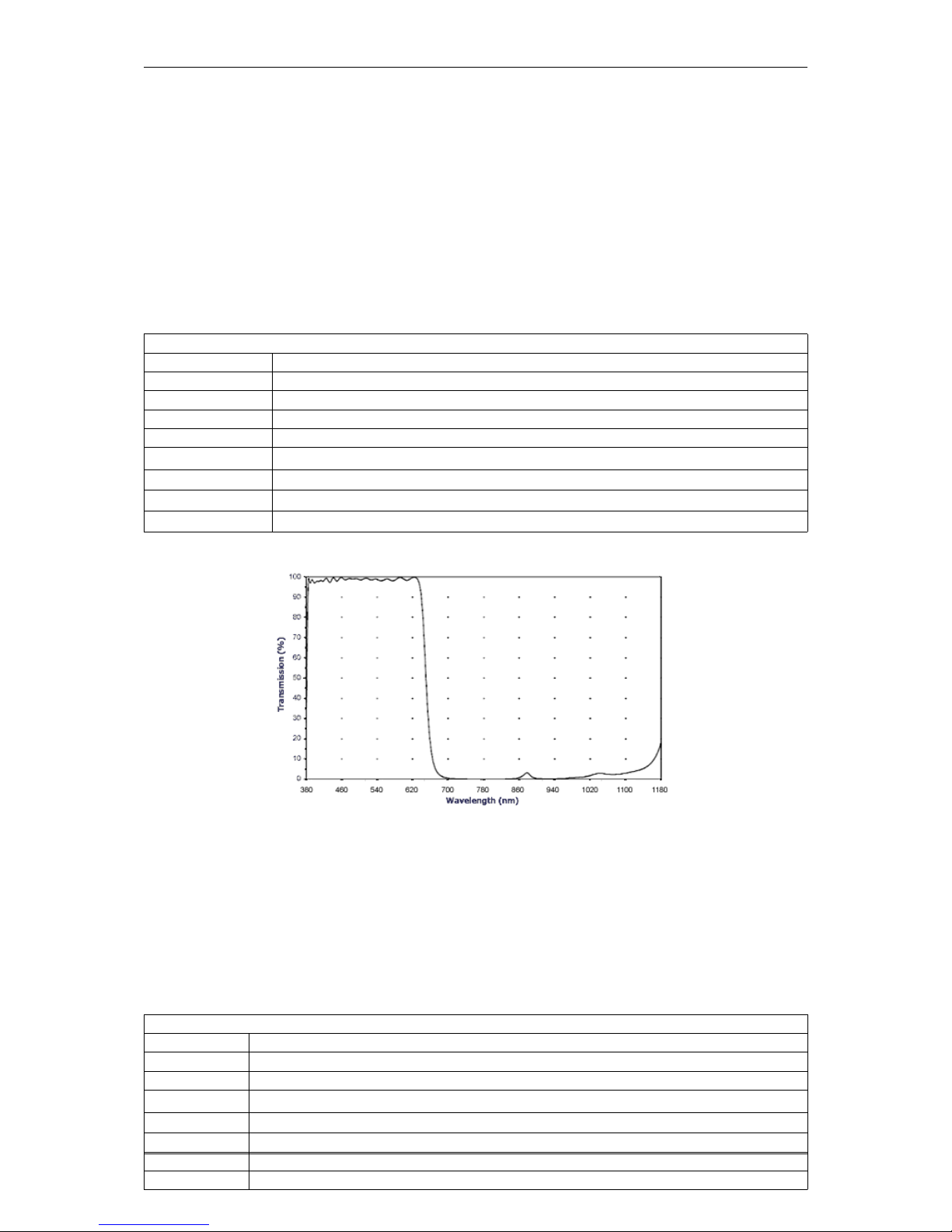
72 CONTENTS
11 Filters and Lenses
MATRIX VISION offers several filters for the mvBlueFOX3camera. The hot mirror filter (p. 72) is part of the
standard delivery condition.
11.1 Hot mirror filter
The hot mirror filter has great transmission in the visible spectrum and blocks out a significant portion of the IR
energy.
Technical data
Diameter 28 mm
Thickness 1.0 mm
Material Borofloat
Characteristics T = 50% @ 650 +/- 10 nm
T > 92% 390-620 nm
R
avg
> 95% 700-1150 nm
AOI = 0 degrees
Surface quality Polished on both sides P4
Surface irregularity 5/3x0.06 on both sides
Figure 1: IR-CUT wavelengths and transmission diagram
11.2 Cold mirror filter
The high-quality daylight cut filter has optically polished surfaces. The polished surface allows the use of the filter
directly in the path of rays in image processing applications. The filter is protected against scratches during the
transport by a protection film that has to be removed before the installing the filter.
Technical data
Diameter 28 mm
Thickness 1.0 mm
Material Solaris S 306
Characteristics T
avg
> 80% > 780 nm
AOI = 0 degrees
Protective foil on both sides
Without antireflexion
Without bezel
MATRIX VISION GmbH
Page 84

11.4 Lenses 73
Figure 2: DL-CUT wavelengths and transmission diagram
11.3 Glass filter
It is also possible to choose a glass filter with following characteristics:
Technical data
Glass thickness 1.0 mm
Material Borofloat without coating
ground with protection chamfer
Surface quality polished on both sides P4
Surface irregularity 5/3x0.06 on both sides
11.4 Lenses
MATRIX VISION offers a high-quality selection of lenses. If you have questions about our accessories, please
contact our sales team: info@matrix-vision.com.
MATRIX VISION GmbH
Page 85

74 CONTENTS
12 Application Usage
12.1 wxPropView
wxPropView (p. 74) is an interactive GUI tool to acquire images and to configure the device and to display and
modify the device properties of MATRIX VISION GmbH hardware. After the installation you can find wxPropView
(p. 74)
• as an icon with the name "wxPropView" on the desktop (Windows) or
• in "∼/mvimpact-acquire/apps/mvPropView/x86" (Linux).
wxPropView - Introduction:
https://www.matrix-vision.com/tl_files/mv11/trainings/wxPropView/wx←-
PropView_Introduction/index.html
12.1.1 How to work with wxPropView
wxPropView - Working with wxPropView:
https://www.matrix-vision.com/tl_files/mv11/trainings/wxPropView/wx←-
PropView_WorkingWith/index.html
Depending on the driver version, wxPropView starts with the Quick Setup Wizard (p. 74) (as soon as a camera
with the right firmware version was selected used or a single camera with the right firmware was found) or without
it (p. 77).
12.1.1.1 Quick Setup Wizard
MATRIX VISION GmbH
Page 86

12.1 wxPropView 75
Since
mvIMPACT Acquire 2.11.3
The Quick Setup Wizard is a tiny and powerful single window configuration tool to optimize the image quality
automatically or to set the most important parameters, which affect the image quality, in an easy way manually:
Figure 1:Quick Setup Wizard started
Depending on the camera spectrum (gray or color sensor), it will automatically pre-set the camera so that image
quality is usually as best as possible.
"For all cameras:"
Image format is chosen as 10 bit (if possible) as a good compromise on image quality and speed.
It will further set
• "Exposure" to Auto,
• "Gain" to Auto,
• "Frame rate" to Auto based on current settings of the camera, and
• switches camera into continuous mode
"In case of gray:"
The above settings will be also applied whenever the "Gray Preset" button is pressed. For gray cameras it is herewith
assumed that image processing prefers a linear camera response.
"In case of color:"
It will additionally set
• "White balance" in the camera to Auto, and will apply
• a host based moderate "Gamma correction" (1.8), and lastly it will apply
• a host (PC) based sensor specific "Color Correction Matrix" and use the respective "sRGB display matrix".
These settings will also be applied whenever the "Color Preset" button is pressed. It is herewith assumed that color
camera image is optimized for best human visual feedback.
MATRIX VISION GmbH
Page 87

76 CONTENTS
12.1.1.1.1 Changing the Presets
There are 3 presets:
• Gray
• Color
• Factory
Factory can be used as a fall back to quickly skip or remove all presets and load the factory default settings.
12.1.1.1.2 Modifying Settings
All auto modes can be switched off and all settings, such as Gain, Exposure etc. can be subsequently modified by
using:
• the sliders,
• the arrow keys, or
• entering real values with your keyboard.
Toggling Gamma button loads or unloads a host based 10 bit Gamma correction with a moderate value of 1.8 into
the signal processing path. Switch Gamma on if you require a gray level camera image to appear natural for the
human eye.
Toggling Color+ button switches both CCM and sRGB display matrix on and off. This optimizes the sensor color
response for the human eye and goes in conjunction with a display color response. Because sRGB displays are
mostly used and this is the default color space in Windows OS, these are preselected. If you require other display
matrices (e.g. Adobe or WideGamut) feel free to use the tree mode of wxPropView and select ColorTwistOutput←-
Correction accordingly.
Setting Black Level
Black level can be used if you require dark portions in the image to appear even darker or brighter. Please note that
this slider combines analog and digital settings meaningfully.
Setting Gain
Gain settings also combine analog and digital registers into one slider setting.
Setting Saturation
Saturation setting increases the color saturation to make the image appear more colored. It does not change
uncolored parts in the image nor changes the color tone or hue.
12.1.1.1.3 How to disable Quick Setup Wizard
Uncheck the checkbox "Show This Display When A Device Is Opened" to disable the Quick Setup Wizard to be
called automatically. Use the "Wizards" menu and select "Quick Setup" to open the Quick Setup Wizard once
again.
12.1.1.1.4 How to Return to the Tree Mode
Use OK to use the values and settings of the Quick Setup Wizard and go back to the tree mode of wxPropView.
Use Cancel to discard the Quick Setup Wizard values and settings and go back to wxPropView and use the former
(or default) settings.
MATRIX VISION GmbH
Page 88

12.1 wxPropView 77
12.1.1.1.5 Image Display Functions
Quick Setup Wizard allows zooming into the image by right clicking in the image area and unchecking "Fit To
Screen" mode. Use the mouse wheel to zoom in or out. Check "Fit To Screen" mode, if you want the complete
camera image to be sized in the window screen size.
12.1.1.1.6 Known Restrictions
In cases of Tungsten (artificial) light, camera brightness may tend to oscillations if Auto functions are used. This
can be minimized or avoided by setting the frame frequency to an integer divisor of the mains frequency.
• Example:
– Europe: 50 Hz; Set frame rate to 100, 50, 25 12.5 fps or appropriate.
– In countries with 60 Hz use 120, 60, 30 or 15. . . accordingly.
12.1.1.2 First View of wxPropView
wxPropView (p.74) consists of several areas:
Figure 2:wxPropView started
MATRIX VISION GmbH
Page 89

78 CONTENTS
• "Menu Bar"
(to work with wxPropView (p.74) using the menu)
• "Upper Tool Bar"
(to select and initialize a device, acquire images, play a recorder sequence)
• "Left Tool Bar"
(to hide and show parts of the GUI)
• "Status Tool Bar"
• "Main Window" with
– "Grid"
(tree control with the device settings accessible by the user)
– "Display"
(for the acquired images)
– "Analysis"
(information about whole images or an AOI)
By clicking on F1 you will get the HELP dialog.
Now, you can initialize a device by
• selecting it in the drop down list in the "Upper Tool Bar" and
• clicking on "Use".
After having successfully initialized a device the tree control in the lower left part of the "Main Window" will display
the properties (settings or parameters) (according to the "interface layout") accessible by the user.
Note
Please have a look at the troubleshooting chapter if you neither see the mvBlueFOX3 nor cannot use it
(p. 138).
You've also got the possibility to set your "User Experience". According to the chosen experience, the level of
visibility is different:
• Beginner (basic camera settings/properties are visible)
• Expert (e.g. all advanced image processing are visible)
• Guru (all settings/properties are visible)
Properties displayed in light grey cannot be modified by the user. Only the properties, which actually have an impact
on the resulting image, will be visible. Therefore, certain properties might appear or disappear when modifying
another properties.
To permanently commit a modification made with the keyboard the ENTER must be pressed. If leaving the editor
before pressing ENTER will restore the old value.
MATRIX VISION GmbH
Page 90

12.1 wxPropView 79
12.1.1.3 How to see the first image
As described earlier, for each recognized device in the system the devices serial number will appear in the drop
down menu in the upper left corner of the "Upper Tool Bar". When this is the first time you start the application after
the system has been booted this might take some seconds when working with devices that are not connected to
the host system via PCI or PCIe.
Once you have selected the device of your choice from the drop down menu click on the "Use" button to open it.
When the device has been opened successfully, the remaining buttons of the dialog will be enabled:
Note
Following screenshots are representative and where made using a mvBlueFOX3 camera as the capturing
device.
For color sensors, it is recommended to perform a white balance (p. 95) calibration before acquiring images. This
will improve the quality of the resulting images significantly.
Figure 3:wxPropView - First start
MATRIX VISION GmbH
Page 91

80 CONTENTS
Now, you can capture an image ("Acquisition Mode": "SingleFrame") or display live images ("Continuous"). Just
• select an "Acquisition Mode" e.g. "SingleFrame" and
• click the "Acquire" button.
Note
The techniques behind the image acquisition can be found in the developers sections.
Figure 4: wxPropView - First image
Three different acquisition modes are available:
• Continuous ("Live Mode")
• MultiFrame ("Number of Single Snaps")
MATRIX VISION GmbH
Page 92

12.1 wxPropView 81
• SingleFrame ("Single Snap")
The frame rate depends on
• the camera,
• the pixel clock of the sensor and
• the "Acquisition Frame Rate".
If you want to have a fixed frame rate using the "Continuous" mode, GenICam (p. 155) offers the property "Setting
-> Base -> Camera -> GenICam -> Acquisition Control -> Acquisition Frame Rate" (from 5 fps to maximum of
the camera in 0.1 increments). Just adapt this property to your needs.
Alternatively, if you need frame rates below 5 fps, you can use Timers. In the use case Creating synchronized
acquisitions using timers (p.277), for example, a frame rate of 1 fps is generated.
12.1.1.3.1 Record Mode
It is also possible to record image sequences using wxPropView.
1. For this, you have to set the size of the recorder in "System Settings -> RequestCount" e.g. to 100.
This will save the last 100 requests in the request queue of the driver, i.e. the image data inluding the request
info like frame number, time stamp, etc.
2. Afterwards you can start the recording by clicking the Rec. button.
3. With the Next and Prev. buttons you can display the single images.
If you switched on the request info overlay (righ-click on the display area and select the entry to activate this
feature), these information will be displayed on the image, too. With the timestamp you can see the interval of the
single frames in microseconds.
MATRIX VISION GmbH
Page 93

82 CONTENTS
Figure 5: wxPropView - Using the record mode.
12.1.1.4 Storing and restoring settings
When wxPropView (p.74) is started for the first time, the values of properties set to their default values will be
displayed in green to indicate that these values have not been modified by the user so far. Modified properties (even
if the value is the same as the default) will be displayed in black.
Figure 6:wxPropView - Storing settings
MATRIX VISION GmbH
Page 94

12.1 wxPropView 83
Settings can be stored in several ways (via the "Menu Bar": "Action -> Capture Settings -> Save"):
• "As Default Settings For All Devices Belonging To The Same Family (Per User Only)": As the start-up param-
eters for every device belonging to the same family, e.g. for mvBlueCOUGAR-X, mvBlueCOUGAR-XD.
• "As Default Settings For All Devices Belonging To The Same Family And Product Type": As the start-up
parameters for every device belonging to the same product, e.g. for any mvBlueCOUGAR-X but not for
mvBlueCOUGAR-XD.
• "As Default Settings For This Device(Serial Number)": As the start-up parameters for the currently selected
device.
• "To A File": As an XML file that can be used e.g. to transport a setting from one machine to another or even
to use the settings configured for one platform on another (Windows <-> Linux).
During the startup of a device, all these setting possibilities show different behaviors. The differences are described
in chapter Settings behaviour during startup (p. 51)
Restoring of settings previously stored works in a similar way. After a device has been opened the settings will be
loaded automatically as described in Settings behaviour during startup (p. 51)
However, at runtime the user can decide to
• explicitly load the device family specific settings stored on this machine (in e.g. wxPropView (p. 74) select
in the "Menu Bar": "Action -> Capture Settings -> Load -> From The Default Settings Location For This
Devices Family (Per User Only)")
• explicitly load the product specific settings stored on this machine (in e.g. wxPropView (p. 74) select in the
"Menu Bar": "Action -> Capture Settings -> Load -> From The Default Settings Location For This Devices
Family And Product Type)")
• explicitly load the device specific settings stored on this machine (in e.g. wxPropView (p. 74) select in the
"Menu Bar": "Action -> Capture Settings -> Load -> From The Default Settings Location For This Device(←-
Serial Number)")
• explicitly load device family specific settings from a XML file previously created in e.g. wxPropView (p. 74)
select in the "Menu Bar": "Action -> Capture Settings -> Load -> From A File"
Warning
Since mvIMPACT Acquire 2.9.0 GenICam devices will be able to save their properties in a XML File, only
if the properties have the streamable attribute set (for more information refer to the GenICam standard
specification). Properties with no streamable attribute set, will be silently ignored when saving, which
means they will not be saved in the XML file. For MATRIX VISION GenICam cameras, starting with firmware
version 1.6.414 the streamable attribute is set for all the necessary properties.
Warning
Since mvIMPACT Acquire 2.9.0 and again in version 2.11.0 storing and loading of camera settings in a XML
file for the GenICam (p. 155) interface layout has been updated. As a result XML files created with newer
versions of mvIMPACT Acquire might not be readable on systems with older version of mvIMPACT Acquire
installed. XML files created on systems with earlier versions of mvIMPACT Acquire will always be readable
this or newer versions. See the following table for details.
MATRIX VISION GmbH
Page 95
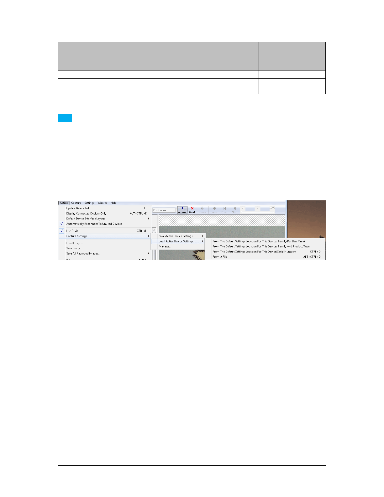
84 CONTENTS
mvIMPACT Acquire
Version
Loading a XML settings
file created with mvI←-
MPACT Acquire version
< 2.9.0
Loading a XML settings
file created with mvI←-
MPACT Acquire version
2.9.0 - 2.10.1
Loading a XML settings
file created with mvI←-
MPACT Acquire version
2.11.0 or later
< 2.9.0 YES NO NO
2.9.0 - 2.10.1 YES YES NO
>= 2.11.0 YES YES YES
Note
For devices operated in the GenICam interface layout further restriction apply: Settings created with a certain
product type can only be used with other devices belonging to the exact same type as defined by the property
Product inside the device list (the one device specific property list that is accessible without initializing the
device before). Even if a setting can be used with various firmware versions it is recommended to use one
setting for multiple devices all updated to the very same firmware version to avoid compatibility problems.
With "Action -> Capture Settings -> Manage..." you can delete the settings which were saved on the system.
Figure 7:wxPropView - Restoring settings
12.1.1.5 Properties
All properties and functions can be displayed in the list control on the lower left side of the dialog. To modify the
value of a property select the edit control right of the properties name. Property values, which refer to the default
value of the device, are displayed in green. A property value once modified by the user will be displayed in black
(even if the value itself has not changed). To restore its default value of a single property
• right click on the name of the property and
• select "Restore Default".
To restore the default value for a complete list (which might include sub-lists)
• right click on the name of a list and
• select "Restore Default".
In this case a popup window will be opened and you have to confirm again.
MATRIX VISION GmbH
Page 96

12.1 wxPropView 85
Figure 8:wxPropView - Restore the default value of a property
Also the user might want to set all (or a certain range of) values for properties that store multiple values with a single
operation. If supported by the property, this can also be achieved by right clicking on the PARENT grid element. If
the property allows this modification the pop up menu will again contain additional entries:
MATRIX VISION GmbH
Page 97

86 CONTENTS
Figure 9:wxPropView - Setting multiple property values
It's possible to either set all (or a range of) elements of the property to a certain value OR to define a value range,
that then will be applied to the range of property elements selected by the user. The following example will explain
how this works:
MATRIX VISION GmbH
Page 98
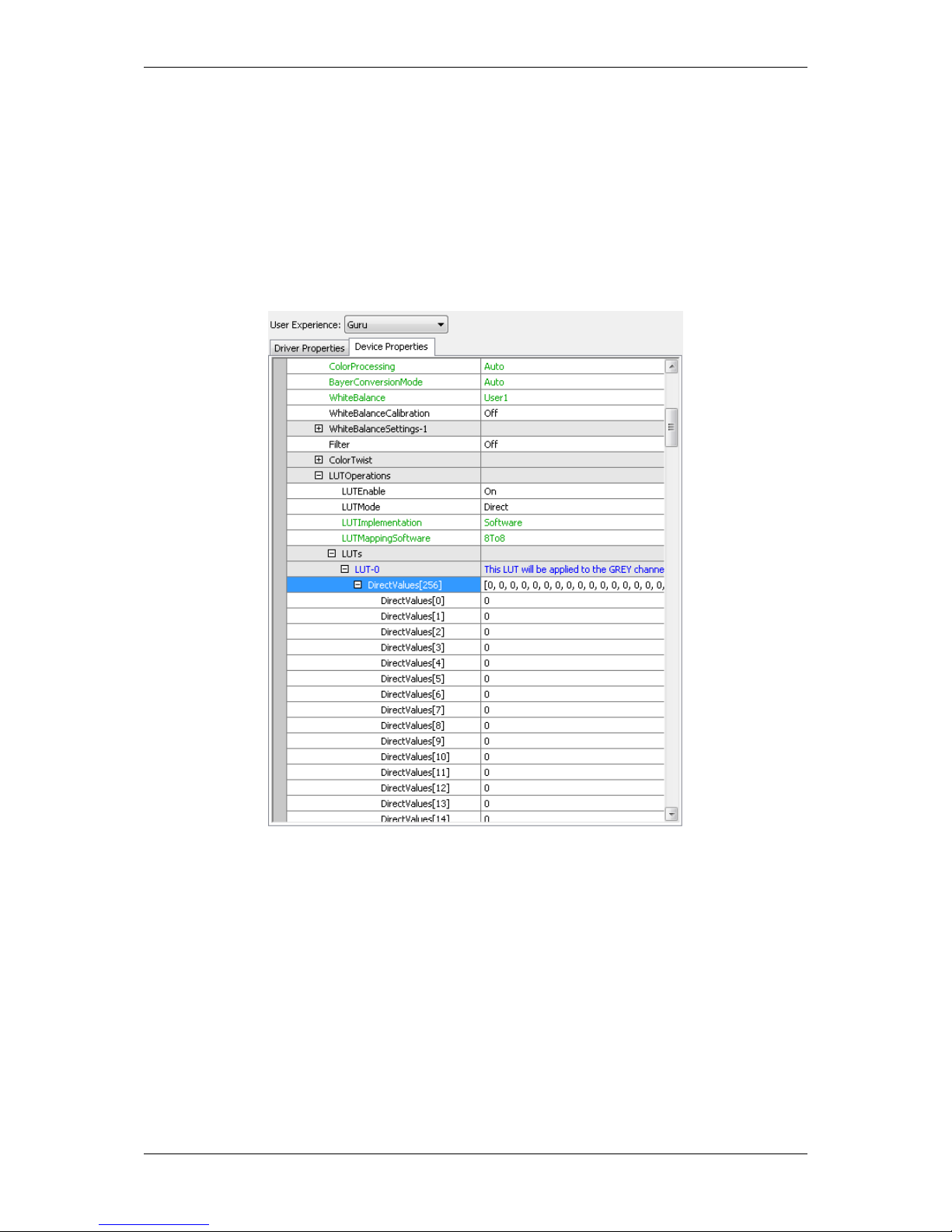
12.1 wxPropView 87
Figure 10:wxPropView - Setting multiple property values within a certain value range
In this sample the entries 0 to 255 of the property will be assigned the value range of 0 to 255. This will result in the
following values AFTER applying the values:
Figure 11:wxPropView - After applying the value range to a property
12.1.1.6 Methods
Method appears as entries in the tree control as well. However, their name and behavior differs significantly from
the behavior of properties. The names of method objects will appear in 'C' syntax like e.g. "int function( char∗, int
)". This will specific a function returning an integer value and expecting a string and an integer as input parameters.
To execute a method object
• right click on the name of a method and
• select "Execute" from the popup menu:
MATRIX VISION GmbH
Page 99
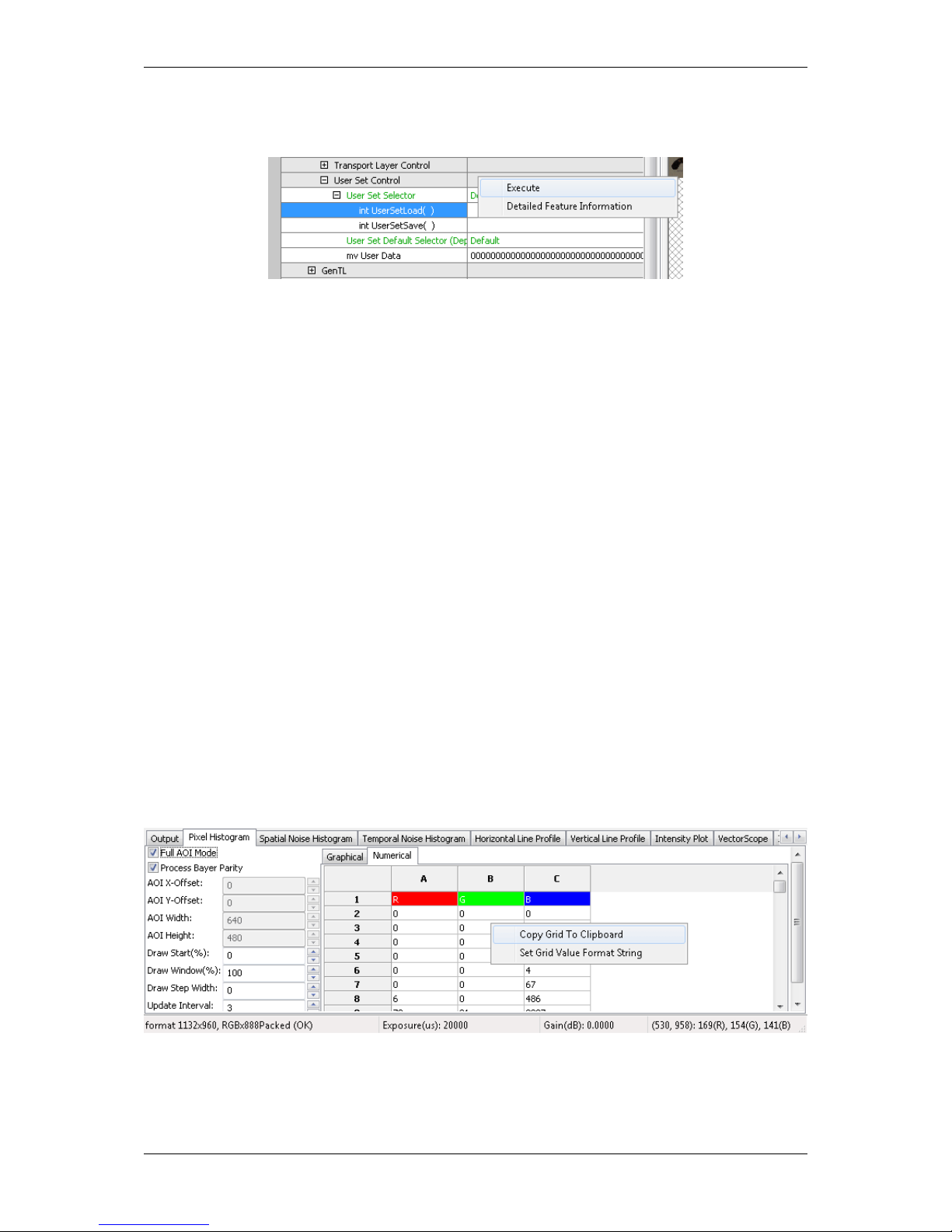
88 CONTENTS
Figure 12:wxPropView - Calling a method object
Parameters can be passed to methods by selecting the edit control left of a method object. Separate the parameters
by blanks. So to call a function expecting a string and an integer value you e.g. might enter "testString 0"
into the edit control left of the method.
The return value (in almost every case an error code as an integer) will be displayed in the lower right corner of the
tree control. The values displayed here directly correspond the error codes defined in the interface reference and
therefore will be of type TDMR_ERROR or TPROPHANDLING_ERROR.
12.1.1.7 Copy grid data to the clipboard
Since wxPropView (p. 74) version 1.11.0 it is possible to copy analysis data to the clipboard. The data will be copied
in CSV style thus can be pasted directly into tools like Open Office™ or Microsoft® Office™.
Just
• right-click on the specific analysis grid when in numerical display mode and
• select "Copy grid to clipboard" from the pop up menu.
Figure 13:wxPropView - Copying grid data to the clipboard
MATRIX VISION GmbH
Page 100

12.1 wxPropView 89
12.1.1.8 Import and Export images
wxPropView (p. 74) offers a wide range of image formats that can be used for exporting captured image to a file.
Some formats e.g. like packed YUV 4:2:2 with 10 bit per component are rather special thus they can't be stored
into a file like e.g. offered by the BMP file header. When a file is stored in a format, that does not support this data
type wxPropView (p.74) will convert this image into something that matches the original image format as close as
possible. This, however, can result in the loss of data. In order to allow the storage of the complete information
contained in a captured image wxPropView (p. 74) allows to store the data in a raw format as well. This file format
will just contain a binary dump of the image with no leader or header information. However, the file name will
automatically be extended by information about the image to allow the restoring of the data at a later time.
All image formats, that can be exported can also be imported again. Importing a file can be done in 3 different
ways:
• via the menu (via the "Menu Bar": "Action -> Load image...")
• by dragging an image file into an image display within wxPropView (p. 74)
• by starting wxPropView (p. 74) from the command line passing the file to open as a command line param-
eter (p. 99) (under Windows® e.g. "wxPropView.exe MyImage.png" followed by [ENTER])
When importing a "∗.raw" image file a small dialog will pop up allowing the user to define the dimensions and
the pixel format of the image. When the file name has been generated using the image storage function offered
by wxPropView (p. 74), the file name will be passed and the extracted information will automatically be set in the
dialog thus the user simply needs to confirm this information is correct.
Figure 14:wxPropView - Raw image file import
12.1.1.9 Setting up multiple display support and/or work with several capture settings in parallel
wxPropView (p.74) is capable of
• dealing with multiple capture settings or acquisition sequences for a single device and in addition to that
• it can be configured to deal with multiple image displays.
The amount of parallel image displays can be configured via the command line parameter (p. 99) "dcx" and
"dcy". In this step by step setup wxPropView (p. 74) has been started like this from the command line:
wxPropView dcx=1 dcy=2
This will result in 1 display in horizontal direction and 2 in vertical direction.
MATRIX VISION GmbH
 Loading...