

Page 1
mvBlueFOX
Technical Manual
Page 2

CONTENTS i
Contents
1 About this manual 2
1.1 Composition of the manual . . . . . . . . . . . . . . . . . . . . . . . . . . . . . . . . . . . . . . 2
1.2 How to get started? . . . . . . . . . . . . . . . . . . . . . . . . . . . . . . . . . . . . . . . . . . 2
1.2.1 Installation . . . . . . . . . . . . . . . . . . . . . . . . . . . . . . . . . . . . . . . . . . 3
1.2.2 Driver concept . . . . . . . . . . . . . . . . . . . . . . . . . . . . . . . . . . . . . . . . 3
1.2.3 Image acquisition concept . . . . . . . . . . . . . . . . . . . . . . . . . . . . . . . . . . 6
1.2.4 Programming . . . . . . . . . . . . . . . . . . . . . . . . . . . . . . . . . . . . . . . . . 6
2 Imprint 7
3 Revisions 8
4 Graphic Symbols 12
4.1 Notes, Warnings, Attentions . . . . . . . . . . . . . . . . . . . . . . . . . . . . . . . . . . . . . . 12
4.2 Webcasts . . . . . . . . . . . . . . . . . . . . . . . . . . . . . . . . . . . . . . . . . . . . . . . 12
5 Important information 13
5.1 High-Speed USB design guidelines . . . . . . . . . . . . . . . . . . . . . . . . . . . . . . . . . . 14
5.2 European Union Declaration of Conformity statement . . . . . . . . . . . . . . . . . . . . . . . . 14
5.3 Legal notice . . . . . . . . . . . . . . . . . . . . . . . . . . . . . . . . . . . . . . . . . . . . . . 17
5.3.1 For customers in the U.S.A. . . . . . . . . . . . . . . . . . . . . . . . . . . . . . . . . . . 17
5.3.2 For customers in Canada . . . . . . . . . . . . . . . . . . . . . . . . . . . . . . . . . . . 18
5.3.3 Pour utilisateurs au Canada . . . . . . . . . . . . . . . . . . . . . . . . . . . . . . . . . 18
6 Introduction 19
6.1 Order code nomenclature . . . . . . . . . . . . . . . . . . . . . . . . . . . . . . . . . . . . . . . 19
6.2 mvBlueFOX . . . . . . . . . . . . . . . . . . . . . . . . . . . . . . . . . . . . . . . . . . . . . . 19
6.3 mvBlueFOX-M . . . . . . . . . . . . . . . . . . . . . . . . . . . . . . . . . . . . . . . . . . . . . 20
6.4 mvBlueFOX-IGC . . . . . . . . . . . . . . . . . . . . . . . . . . . . . . . . . . . . . . . . . . . 20
6.5 mvBlueFOX-MLC . . . . . . . . . . . . . . . . . . . . . . . . . . . . . . . . . . . . . . . . . . . 21
6.6 What's inside and accessories . . . . . . . . . . . . . . . . . . . . . . . . . . . . . . . . . . . . 22
MATRIX VISION GmbH
Page 3

ii CONTENTS
7 Quickstart 24
7.1 Windows . . . . . . . . . . . . . . . . . . . . . . . . . . . . . . . . . . . . . . . . . . . . . . . . 24
7.1.1 System Requirements . . . . . . . . . . . . . . . . . . . . . . . . . . . . . . . . . . . . 24
7.1.2 Installing the mvIMPACT Acquire driver . . . . . . . . . . . . . . . . . . . . . . . . . . . 25
7.1.3 Installing the hardware . . . . . . . . . . . . . . . . . . . . . . . . . . . . . . . . . . . . 27
7.2 Linux . . . . . . . . . . . . . . . . . . . . . . . . . . . . . . . . . . . . . . . . . . . . . . . . . . 31
7.2.1 System Requirements . . . . . . . . . . . . . . . . . . . . . . . . . . . . . . . . . . . . 31
7.2.2 Installing the mvIMPACT Acquire driver . . . . . . . . . . . . . . . . . . . . . . . . . . . 33
7.2.3 Installing the hardware . . . . . . . . . . . . . . . . . . . . . . . . . . . . . . . . . . . . 39
7.3 Relationship between driver, firmware and FPGA file . . . . . . . . . . . . . . . . . . . . . . . . . 39
7.3.1 FPGA . . . . . . . . . . . . . . . . . . . . . . . . . . . . . . . . . . . . . . . . . . . . . 40
7.3.2 Firmware . . . . . . . . . . . . . . . . . . . . . . . . . . . . . . . . . . . . . . . . . . . 41
7.4 Settings behaviour during startup . . . . . . . . . . . . . . . . . . . . . . . . . . . . . . . . . . . 42
8 Technical data 45
8.1 Power supply . . . . . . . . . . . . . . . . . . . . . . . . . . . . . . . . . . . . . . . . . . . . . 45
8.2 Standard version (mvBlueFOX-xxx) . . . . . . . . . . . . . . . . . . . . . . . . . . . . . . . . . . 45
8.2.1 Dimensions and connectors . . . . . . . . . . . . . . . . . . . . . . . . . . . . . . . . . 45
8.2.2 LED states . . . . . . . . . . . . . . . . . . . . . . . . . . . . . . . . . . . . . . . . . . 50
8.2.3 Components . . . . . . . . . . . . . . . . . . . . . . . . . . . . . . . . . . . . . . . . . 50
8.3 Board-level version (mvBlueFOX-Mxxx) . . . . . . . . . . . . . . . . . . . . . . . . . . . . . . . 51
8.3.1 Dimensions and connectors . . . . . . . . . . . . . . . . . . . . . . . . . . . . . . . . . 51
8.3.2 LED states . . . . . . . . . . . . . . . . . . . . . . . . . . . . . . . . . . . . . . . . . . 56
8.3.3 Components . . . . . . . . . . . . . . . . . . . . . . . . . . . . . . . . . . . . . . . . . 56
8.3.4 Accessories mvBlueFOX-Mxxx . . . . . . . . . . . . . . . . . . . . . . . . . . . . . . . . 56
8.4 Single-board version (mvBlueFOX-MLC2xx) . . . . . . . . . . . . . . . . . . . . . . . . . . . . . 59
8.4.1 Typical Power consumption @ 5V . . . . . . . . . . . . . . . . . . . . . . . . . . . . . . 59
8.4.2 Dimensions and connectors . . . . . . . . . . . . . . . . . . . . . . . . . . . . . . . . . 59
8.4.3 LED states . . . . . . . . . . . . . . . . . . . . . . . . . . . . . . . . . . . . . . . . . . 66
8.4.4 Assembly variants . . . . . . . . . . . . . . . . . . . . . . . . . . . . . . . . . . . . . . 66
8.5 Single-board version with housing (mvBlueFOX-IGC2xx) . . . . . . . . . . . . . . . . . . . . . . 67
8.5.1 Dimensions and connectors . . . . . . . . . . . . . . . . . . . . . . . . . . . . . . . . . 67
8.5.2 LED states . . . . . . . . . . . . . . . . . . . . . . . . . . . . . . . . . . . . . . . . . . 68
8.5.3 Positioning tolerances of sensor chip . . . . . . . . . . . . . . . . . . . . . . . . . . . . . 69
MATRIX VISION GmbH
Page 4

CONTENTS iii
9 Sensor overview 70
9.1 CCD sensors . . . . . . . . . . . . . . . . . . . . . . . . . . . . . . . . . . . . . . . . . . . . . 70
9.2 CMOS sensors . . . . . . . . . . . . . . . . . . . . . . . . . . . . . . . . . . . . . . . . . . . . 72
9.3 Output sequence of color sensors (RGB Bayer) . . . . . . . . . . . . . . . . . . . . . . . . . . . 73
9.4 Bilinear interpolation of color sensors (RGB Bayer) . . . . . . . . . . . . . . . . . . . . . . . . . . 74
10 Filters 75
10.1 Hot mirror filter . . . . . . . . . . . . . . . . . . . . . . . . . . . . . . . . . . . . . . . . . . . . . 75
10.2 Cold mirror filter . . . . . . . . . . . . . . . . . . . . . . . . . . . . . . . . . . . . . . . . . . . . 75
10.3 Glass filter . . . . . . . . . . . . . . . . . . . . . . . . . . . . . . . . . . . . . . . . . . . . . . . 76
11 Application Usage 77
11.1 wxPropView . . . . . . . . . . . . . . . . . . . . . . . . . . . . . . . . . . . . . . . . . . . . . . 77
11.1.1 How to work with wxPropView . . . . . . . . . . . . . . . . . . . . . . . . . . . . . . . . 77
11.1.2 How to configure a device . . . . . . . . . . . . . . . . . . . . . . . . . . . . . . . . . . 101
11.1.3 Command-line options . . . . . . . . . . . . . . . . . . . . . . . . . . . . . . . . . . . . 115
11.2 mvDeviceConfigure . . . . . . . . . . . . . . . . . . . . . . . . . . . . . . . . . . . . . . . . . . 116
11.2.1 How to set the device ID . . . . . . . . . . . . . . . . . . . . . . . . . . . . . . . . . . . 116
11.2.2 How to update the firmware . . . . . . . . . . . . . . . . . . . . . . . . . . . . . . . . . . 118
11.2.3 How to disable CPU sleep states a.k.a. C states (< Windows 8) . . . . . . . . . . . . . . 120
11.2.4 Command-line options . . . . . . . . . . . . . . . . . . . . . . . . . . . . . . . . . . . . 122
12 HRTC - Hardware Real-Time Controller 124
12.1 Introduction . . . . . . . . . . . . . . . . . . . . . . . . . . . . . . . . . . . . . . . . . . . . . . 124
12.1.1 Operating codes . . . . . . . . . . . . . . . . . . . . . . . . . . . . . . . . . . . . . . . 124
12.2 How to use the HRTC . . . . . . . . . . . . . . . . . . . . . . . . . . . . . . . . . . . . . . . . . 124
13 C developers 126
14 C++ developers 127
15 .NET developers 128
MATRIX VISION GmbH
Page 5

iv CONTENTS
16 Python developers 129
16.1 Introduction . . . . . . . . . . . . . . . . . . . . . . . . . . . . . . . . . . . . . . . . . . . . . . 129
16.2 Building . . . . . . . . . . . . . . . . . . . . . . . . . . . . . . . . . . . . . . . . . . . . . . . . 129
16.2.1 Windows . . . . . . . . . . . . . . . . . . . . . . . . . . . . . . . . . . . . . . . . . . . 129
16.2.2 Linux . . . . . . . . . . . . . . . . . . . . . . . . . . . . . . . . . . . . . . . . . . . . . 130
16.3 Using . . . . . . . . . . . . . . . . . . . . . . . . . . . . . . . . . . . . . . . . . . . . . . . . . 130
17 DirectShow Interface 133
17.1 Supported Interfaces . . . . . . . . . . . . . . . . . . . . . . . . . . . . . . . . . . . . . . . . . 133
17.1.1 IAMCameraControl . . . . . . . . . . . . . . . . . . . . . . . . . . . . . . . . . . . . . . 133
17.1.2 IAMDroppedFrames . . . . . . . . . . . . . . . . . . . . . . . . . . . . . . . . . . . . . 133
17.1.3 IAMStreamConfig . . . . . . . . . . . . . . . . . . . . . . . . . . . . . . . . . . . . . . . 133
17.1.4 IAMVideoProcAmp . . . . . . . . . . . . . . . . . . . . . . . . . . . . . . . . . . . . . . 133
17.1.5 IKsPropertySet . . . . . . . . . . . . . . . . . . . . . . . . . . . . . . . . . . . . . . . . 133
17.1.6 ISpecifyPropertyPages . . . . . . . . . . . . . . . . . . . . . . . . . . . . . . . . . . . . 133
17.2 Logging . . . . . . . . . . . . . . . . . . . . . . . . . . . . . . . . . . . . . . . . . . . . . . . . 133
17.3 Registering and renaming devices for DirectShow usage . . . . . . . . . . . . . . . . . . . . . . . 134
17.3.1 Registering devices . . . . . . . . . . . . . . . . . . . . . . . . . . . . . . . . . . . . . . 134
17.3.2 Renaming devices . . . . . . . . . . . . . . . . . . . . . . . . . . . . . . . . . . . . . . 136
17.3.3 Make silent registration . . . . . . . . . . . . . . . . . . . . . . . . . . . . . . . . . . . . 137
18 Troubleshooting 138
18.1 Accessing log files . . . . . . . . . . . . . . . . . . . . . . . . . . . . . . . . . . . . . . . . . . . 138
18.1.1 Windows . . . . . . . . . . . . . . . . . . . . . . . . . . . . . . . . . . . . . . . . . . . 138
18.1.2 Linux . . . . . . . . . . . . . . . . . . . . . . . . . . . . . . . . . . . . . . . . . . . . . 138
MATRIX VISION GmbH
Page 6

CONTENTS v
19 Use cases 139
19.1 Introducing acquisition / recording possibilities . . . . . . . . . . . . . . . . . . . . . . . . . . . . 139
19.1.1 Generating very long exposure times . . . . . . . . . . . . . . . . . . . . . . . . . . . . . 139
19.1.2 Using VLC Media Player . . . . . . . . . . . . . . . . . . . . . . . . . . . . . . . . . . . 140
19.2 Improving the acquisition / image quality . . . . . . . . . . . . . . . . . . . . . . . . . . . . . . . 142
19.2.1 Correcting image errors of a sensor . . . . . . . . . . . . . . . . . . . . . . . . . . . . . 143
19.2.2 Optimizing the color fidelity of the camera . . . . . . . . . . . . . . . . . . . . . . . . . . 151
19.3 Working with triggers . . . . . . . . . . . . . . . . . . . . . . . . . . . . . . . . . . . . . . . . . 160
19.3.1 Using external trigger with CMOS sensors . . . . . . . . . . . . . . . . . . . . . . . . . . 160
19.4 Working with HDR (High Dynamic Range Control) . . . . . . . . . . . . . . . . . . . . . . . . . . 161
19.4.1 Adjusting sensor -x00w . . . . . . . . . . . . . . . . . . . . . . . . . . . . . . . . . . . . 161
19.4.2 Adjusting sensor -x02d (-1012d) . . . . . . . . . . . . . . . . . . . . . . . . . . . . . . . 165
19.5 Working with LUTs . . . . . . . . . . . . . . . . . . . . . . . . . . . . . . . . . . . . . . . . . . 167
19.5.1 Introducing LUTs . . . . . . . . . . . . . . . . . . . . . . . . . . . . . . . . . . . . . . . 168
19.6 Saving data on the device . . . . . . . . . . . . . . . . . . . . . . . . . . . . . . . . . . . . . . . 170
19.6.1 Creating user data entries . . . . . . . . . . . . . . . . . . . . . . . . . . . . . . . . . . 171
19.7 Working with device features . . . . . . . . . . . . . . . . . . . . . . . . . . . . . . . . . . . . . 173
19.8 Working with several cameras simultaneously . . . . . . . . . . . . . . . . . . . . . . . . . . . . 173
19.8.1 Using 2 mvBlueFOX-MLC cameras in Master-Slave mode . . . . . . . . . . . . . . . . . . 173
19.8.2 Synchronize the cameras to expose at the same time . . . . . . . . . . . . . . . . . . . . 178
19.9 Working with the Hardware Real-Time Controller (HRTC) . . . . . . . . . . . . . . . . . . . . . . 179
19.9.1 Single camera samples (HRTC) . . . . . . . . . . . . . . . . . . . . . . . . . . . . . . . 180
19.9.2 Multiple camera samples (HRTC) . . . . . . . . . . . . . . . . . . . . . . . . . . . . . . 188
MATRIX VISION GmbH
Page 7

vi CONTENTS
20 Appendix A.1 CCD specific camera / sensor data 190
20.1 mvBlueFOX-[Model]220 (0.3 Mpix [640 x 480]) . . . . . . . . . . . . . . . . . . . . . . . . . . . . 190
20.1.1 Introduction . . . . . . . . . . . . . . . . . . . . . . . . . . . . . . . . . . . . . . . . . . 190
20.1.2 Details of operation . . . . . . . . . . . . . . . . . . . . . . . . . . . . . . . . . . . . . . 190
20.1.3 CCD Timing . . . . . . . . . . . . . . . . . . . . . . . . . . . . . . . . . . . . . . . . . . 191
20.1.4 Reprogramming CCD Timing . . . . . . . . . . . . . . . . . . . . . . . . . . . . . . . . . 192
20.1.5 CCD Sensor Data . . . . . . . . . . . . . . . . . . . . . . . . . . . . . . . . . . . . . . . 193
20.1.6 CCD Signal Processing . . . . . . . . . . . . . . . . . . . . . . . . . . . . . . . . . . . . 197
20.1.7 Device Feature And Property List . . . . . . . . . . . . . . . . . . . . . . . . . . . . . . . 198
20.2 mvBlueFOX-[Model]220a (0.3 Mpix [640 x 480]) . . . . . . . . . . . . . . . . . . . . . . . . . . . 198
20.2.1 Introduction . . . . . . . . . . . . . . . . . . . . . . . . . . . . . . . . . . . . . . . . . . 198
20.2.2 Details of operation . . . . . . . . . . . . . . . . . . . . . . . . . . . . . . . . . . . . . . 198
20.2.3 CCD Timing . . . . . . . . . . . . . . . . . . . . . . . . . . . . . . . . . . . . . . . . . . 199
20.2.4 Reprogramming CCD Timing . . . . . . . . . . . . . . . . . . . . . . . . . . . . . . . . . 201
20.2.5 CCD Sensor Data . . . . . . . . . . . . . . . . . . . . . . . . . . . . . . . . . . . . . . . 201
20.2.6 Device Feature And Property List . . . . . . . . . . . . . . . . . . . . . . . . . . . . . . . 205
20.3 mvBlueFOX-[Model]221 (0.8 Mpix [1024 x 768]) . . . . . . . . . . . . . . . . . . . . . . . . . . . 206
20.3.1 Introduction . . . . . . . . . . . . . . . . . . . . . . . . . . . . . . . . . . . . . . . . . . 206
20.3.2 Details of operation . . . . . . . . . . . . . . . . . . . . . . . . . . . . . . . . . . . . . . 206
20.3.3 CCD Timing . . . . . . . . . . . . . . . . . . . . . . . . . . . . . . . . . . . . . . . . . . 207
20.3.4 Reprogramming CCD Timing . . . . . . . . . . . . . . . . . . . . . . . . . . . . . . . . . 208
20.3.5 CCD Sensor Data . . . . . . . . . . . . . . . . . . . . . . . . . . . . . . . . . . . . . . . 209
20.3.6 CCD Signal Processing . . . . . . . . . . . . . . . . . . . . . . . . . . . . . . . . . . . . 214
20.3.7 Device Feature And Property List . . . . . . . . . . . . . . . . . . . . . . . . . . . . . . . 214
20.4 mvBlueFOX-[Model]223 (1.4 Mpix [1360 x 1024]) . . . . . . . . . . . . . . . . . . . . . . . . . . 214
20.4.1 Introduction . . . . . . . . . . . . . . . . . . . . . . . . . . . . . . . . . . . . . . . . . . 214
20.4.2 Details of operation . . . . . . . . . . . . . . . . . . . . . . . . . . . . . . . . . . . . . . 214
20.4.3 CCD Timing . . . . . . . . . . . . . . . . . . . . . . . . . . . . . . . . . . . . . . . . . . 215
20.4.4 Reprogramming CCD Timing . . . . . . . . . . . . . . . . . . . . . . . . . . . . . . . . . 216
20.4.5 CCD Sensor Data . . . . . . . . . . . . . . . . . . . . . . . . . . . . . . . . . . . . . . . 217
20.4.6 CCD Signal Processing . . . . . . . . . . . . . . . . . . . . . . . . . . . . . . . . . . . . 221
20.4.7 Device Feature And Property List . . . . . . . . . . . . . . . . . . . . . . . . . . . . . . . 222
20.5 mvBlueFOX-[Model]224 (1.9 Mpix [1600 x 1200]) . . . . . . . . . . . . . . . . . . . . . . . . . . 222
20.5.1 Introduction . . . . . . . . . . . . . . . . . . . . . . . . . . . . . . . . . . . . . . . . . . 222
20.5.2 Details of operation . . . . . . . . . . . . . . . . . . . . . . . . . . . . . . . . . . . . . . 222
20.5.3 CCD Timing . . . . . . . . . . . . . . . . . . . . . . . . . . . . . . . . . . . . . . . . . . 223
20.5.4 Reprogramming CCD Timing . . . . . . . . . . . . . . . . . . . . . . . . . . . . . . . . . 225
20.5.5 CCD Sensor Data . . . . . . . . . . . . . . . . . . . . . . . . . . . . . . . . . . . . . . . 225
20.5.6 CCD Signal Processing . . . . . . . . . . . . . . . . . . . . . . . . . . . . . . . . . . . . 229
20.5.7 Device Feature And Property List . . . . . . . . . . . . . . . . . . . . . . . . . . . . . . . 230
MATRIX VISION GmbH
Page 8

CONTENTS 1
21 Appendix A.3 CMOS specific camera / sensor data 231
21.1 mvBlueFOX-[Model]200w (0.4 Mpix [752 x 480]) . . . . . . . . . . . . . . . . . . . . . . . . . . . 231
21.1.1 Introduction . . . . . . . . . . . . . . . . . . . . . . . . . . . . . . . . . . . . . . . . . . 231
21.1.2 Details of operation . . . . . . . . . . . . . . . . . . . . . . . . . . . . . . . . . . . . . . 231
21.1.3 Measured frame rates . . . . . . . . . . . . . . . . . . . . . . . . . . . . . . . . . . . . 232
21.1.4 Sensor Data . . . . . . . . . . . . . . . . . . . . . . . . . . . . . . . . . . . . . . . . . . 233
21.1.5 Device Feature And Property List . . . . . . . . . . . . . . . . . . . . . . . . . . . . . . . 234
21.2 mvBlueFOX-[Model]202a (1.3 Mpix [1280 x 1024]) . . . . . . . . . . . . . . . . . . . . . . . . . . 234
21.2.1 Introduction . . . . . . . . . . . . . . . . . . . . . . . . . . . . . . . . . . . . . . . . . . 234
21.2.2 Details of operation . . . . . . . . . . . . . . . . . . . . . . . . . . . . . . . . . . . . . . 234
21.2.3 Sensor Data . . . . . . . . . . . . . . . . . . . . . . . . . . . . . . . . . . . . . . . . . . 236
21.2.4 Characteristics . . . . . . . . . . . . . . . . . . . . . . . . . . . . . . . . . . . . . . . . 236
21.2.5 Device Feature And Property List . . . . . . . . . . . . . . . . . . . . . . . . . . . . . . . 237
21.3 mvBlueFOX-[Model]202b (1.2 Mpix [1280 x 960]) . . . . . . . . . . . . . . . . . . . . . . . . . . 237
21.3.1 Introduction . . . . . . . . . . . . . . . . . . . . . . . . . . . . . . . . . . . . . . . . . . 237
21.3.2 Details of operation . . . . . . . . . . . . . . . . . . . . . . . . . . . . . . . . . . . . . . 237
21.3.3 Measured frame rates . . . . . . . . . . . . . . . . . . . . . . . . . . . . . . . . . . . . 239
21.3.4 Sensor Data . . . . . . . . . . . . . . . . . . . . . . . . . . . . . . . . . . . . . . . . . . 239
21.3.5 Device Feature And Property List . . . . . . . . . . . . . . . . . . . . . . . . . . . . . . . 240
21.4 mvBlueFOX-[Model]202d (1.2 Mpix [1280 x 960]) . . . . . . . . . . . . . . . . . . . . . . . . . . 241
21.4.1 Introduction . . . . . . . . . . . . . . . . . . . . . . . . . . . . . . . . . . . . . . . . . . 241
21.4.2 Details of operation . . . . . . . . . . . . . . . . . . . . . . . . . . . . . . . . . . . . . . 241
21.4.3 Measured frame rates . . . . . . . . . . . . . . . . . . . . . . . . . . . . . . . . . . . . 242
21.4.4 Sensor Data . . . . . . . . . . . . . . . . . . . . . . . . . . . . . . . . . . . . . . . . . . 243
21.4.5 Device Feature And Property List . . . . . . . . . . . . . . . . . . . . . . . . . . . . . . . 244
21.5 mvBlueFOX-[Model]205 (5.0 Mpix [2592 x 1944]) . . . . . . . . . . . . . . . . . . . . . . . . . . 244
21.5.1 Introduction . . . . . . . . . . . . . . . . . . . . . . . . . . . . . . . . . . . . . . . . . . 244
21.5.2 Details of operation . . . . . . . . . . . . . . . . . . . . . . . . . . . . . . . . . . . . . . 244
21.5.3 Measured frame rates . . . . . . . . . . . . . . . . . . . . . . . . . . . . . . . . . . . . 246
21.5.4 Sensor Data . . . . . . . . . . . . . . . . . . . . . . . . . . . . . . . . . . . . . . . . . . 247
21.5.5 Device Feature And Property List . . . . . . . . . . . . . . . . . . . . . . . . . . . . . . . 248
MATRIX VISION GmbH
Page 9

2 CONTENTS
1 About this manual
1.1 Composition of the manual
This manual is based on a modular concept and contains several individual books. That means like in many objectoriented programming languages for each specific functionality you will have your own "class". Instead of classes,
you have books. For example, if you want to know anything about the GUI based applications, then you have to go
to the Application Usage (p. 77) book. If you want to know how images are acquired with your device, have a look
in the respective programming language chapter.
Here is a short summary about all books that form this manual:
• The manual starts with technical data about the device like sensors (for cameras) or electrical characteristics
as well as a quick start chapter.
Afterwards, you will find the different books:
• The installation package comes with a couple of tools offering a graphical user interface (GUI (p. 77)) to
control mvIMPACT Acquire compliant devices.
– wxPropView (p.77) can be used to capture image data and to change parameters like AOI or gain
– mvDeviceConfigure (p. 116) can be used to e.g. perform firmware updates, assign a unique ID to a
device that is stored in non-volatile memory or to configure to log-message output.
• HRTC - Hardware Real-Time Controller (p. 124)
– It is possible to define sequences of operating steps to control acquisition or time critical I/O. This FPGA
built-in functionality is called Hardware Real-Time Controller (short: HRTC).
• DirectShow developers (p. 133)
– This is the documentation of the MATRIX VISION DirectShow_acquire interface.
• Use cases (p. 139)
– This book offers solutions and explanations for standard use cases.
For C, C++, .NET developers, there are separate mvIMPACT Acquire manuals describing the API. Please refer to
the Programming (p.6) section
These documents can either be downloaded from http://www.matrix-vision.com or come as part of an
installation package. The manuals e.g. contain information about
• how to link and build applications using mvIMPACT Acquire
• how the log output for mvIMPACT Acquire devices is configured and how it works in general
• how to create custom client installers packages for Windows and Linux
• the API itself
1.2 How to get started?
This chapter gives you a short overview, how to get started with your device and where to find the necessary
information in the manual. It will also explain or link to the concepts behind the driver and the image acquisition.
Furthermore it explains how to get started programming own applications.
MATRIX VISION GmbH
Page 10

1.2 How to get started? 3
1.2.1 Installation
To install the mvBlueFOX properly you have to follow these steps:
(Please follow the links for detailed descriptions.)
• Windows:
– Check the system requirements (p.24).
– Install the software and driver (p. 25).
– Install the hardware (p.27).
– Configure the mvBlueFOX (p. 77)
e.g. make a white balance (p. 102) (color sensors).
*
• Linux:
– Check the system requirements (p.31).
– Install the software and driver (p. 33).
– Install the hardware (p.39).
– Configure the mvBlueFOX (p. 77)
e.g. make a white balance (p. 102) (color sensors).
*
1.2.2 Driver concept
The driver supplied with the MATRIX VISION product represents the port between the programmer and the
hardware. The driver concept of MATRIX VISION provides a standardized programming interface to all image
processing products (excluding mvBlueLYNX) made by MATRIX VISION GmbH.
The advantage of this concept for the programmer is that a developed application runs without the need for any
major modifications to the various image processing products made by MATRIX VISION GmbH. You can also
incorporate new driver versions, which are available for download free of charge on our website: http://www.←-
matrix-vision.com.
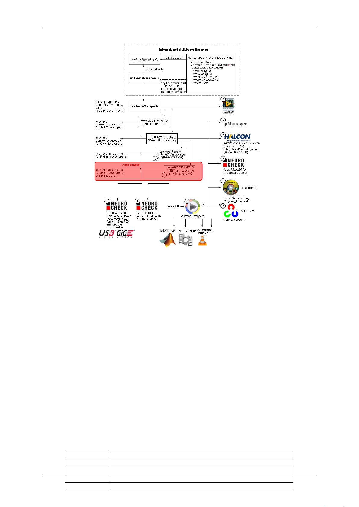
The following diagram shows a schematic structure of the driver concept:
MATRIX VISION GmbH
Page 11
4 CONTENTS
Figure 1: Driver concept
• 1 Part of any mvIMPACT Acquire driver installation package (Windows).
• 2 Separately available for 32 bit and 64 bit. Requires at least one installed driver package.
• 3 See 2, but requires an installed version of the mvBlueFOX driver.
• 4 Part of the NeuroCheck installer but requires at least one installed frame grabber driver.
• 5 Part of the mvIMPACT SDK installation. However, new designs should use the .NET libs that are now part
of mvIMPACT Acquire ("mv.impact.acquire.dll"). The namespace "mv.impact.acquire" of
"mv.impact.acquire.dll" provides a more natural and more efficient access to the same features
as contained in the namespace "mvIMPACT_NET.acquire" of "mvIMPACT_NET.dll", which is why
the latter one should only be used for backward compatibility but NOT when developing a new application.
• 6 Part of Micro-Manager.
1.2.2.1 NeuroCheck support
A couple of devices are supported by NeuroCheck. However between NeuroCheck 5.x and NeuroCheck 6.x there
has been a breaking change in the internal interfaces. Therefore also the list of supported devices differs from one
version to another and some additional libraries might be required.
For NeuroCheck 5.x the following devices are supported:
Device Additional software needed
mvTITAN-G1 mvSDK driver for mvTITAN/mvGAMMA devices
mvTITAN-CL mvSDK driver for mvTITAN/mvGAMMA devices
mvGAMMA-CL mvSDK driver for mvTITAN/mvGAMMA devices
mvBlueFOX mvIMPACT Acquire driver for mvBlueFOX devices, "NCUSBmvBF.dll"
MATRIX VISION GmbH
Page 12

1.2 How to get started? 5
For NeuroCheck 6.0 the following devices are supported:
Device Additional software needed
mvTITAN-G1 mvIMPACT Acquire driver for mvTITAN/mvGAMMA de-
vices
mvTITAN-CL mvIMPACT Acquire driver for mvTITAN/mvGAMMA de-
vices
mvGAMMA-CL mvIMPACT Acquire driver for mvTITAN/mvGAMMA de-
vices
mvHYPERION-CLb mvIMPACT Acquire driver for mvHYPERION devices
Every other mvIMPACT Acquire compliant device mvIMPACT Acquire driver for the corresponding device
family, "mv.impact.acquire.NeuroCheck6.←-
dll" (comes with the driver package, but the driver
package must be installed AFTER installing NeuroCheck 6
For NeuroCheck 6.1 the following devices are supported:
Device Additional software needed
mvTITAN-G1 mvIMPACT Acquire driver for mvTITAN/mvGAMMA de-
vices
mvTITAN-CL mvIMPACT Acquire driver for mvTITAN/mvGAMMA de-
vices
mvGAMMA-CL mvIMPACT Acquire driver for mvTITAN/mvGAMMA de-
vices
mvHYPERION-CLb mvIMPACT Acquire driver for mvHYPERION devices
Every other mvIMPACT Acquire compliant device mvIMPACT Acquire driver for the corresponding device
family, "mv.impact.acquire.NeuroCheck6_←-
1.dll" (comes with the driver package, but the driver
package must be installed AFTER installing NeuroCheck
6.1
1.2.2.2 VisionPro support
Every mvIMPACT Acquire driver package under Windows comes with an adapter to VisionPro from Cognex. The
installation order does not matter. After the driver package and VisionPro has been installed, the next time VisionPro
is started it will allow selecting the mvIMPACT Acquire device. No additional steps are needed.
MATRIX VISION devices that also comply with the GigE Vision or USB3 Vision standard don't need any software
at all, but can also use VisionPro's built-in GigE Vision or USB3 Vision support.
1.2.2.3 HALCON support
HALCON comes with built-in support for mvIMPACT Acquire compliant devices, so once a device driver has been
installed for the mvIMPACT Acquire device, it can also be operated from a HALCON environment using the corresponding acquisition interface. No additional steps are needed.
MATRIX VISION devices that also comply with the GigE Vision or USB3 Vision standard don't need any software
at all, but can also use HALCON's built-in GigE Vision or USB3 Vision support.
As some mvIMPACT Acquire device driver packages also come with a GenTL compliant interface, these can also
be operated through HALCON's built-in GenTL acquisition interface.
MATRIX VISION GmbH
Page 13

6 CONTENTS
1.2.2.4 LabVIEW support
Every mvIMPACT Acquire compliant device can be operated under LabVIEW through an additional set of VIs which
is shipped by MATRIX VISION as a separate installation ("mvLabVIEW Acquire").
MATRIX VISION devices that also comply with the GigE Vision or USB3 Vision standard don't need any additional
software at all, but can also be operated through LabVIEW's GigE Vision or USB3 Vision driver packages.
1.2.2.5 DirectShow support
Every mvIMPACT Acquire compliant device driver package comes with an interface to DirectShow. In order to be
usable from a DirectShow compliant application, devices must first be registered for DirectShow support. How to
this is explained here (p.134).
1.2.2.6 Micro-Manager support
Every mvIMPACT Acquire compliant device can be operated under https://micro-manager.org when
using mvIMPACT Acquire 2.18.0 or later and at least Micro-Manager 1.4.23 build AFTER 15.12.2016. The
adapter needed is part of the Micro-Manager release. Additional information can be found here: https←-
://micro-manager.org/wiki/MatrixVision.
1.2.2.6.1 code
• https://valelab4.ucsf.edu/svn/micromanager2/trunk/DeviceAdapters/Matrix←-
Vision/
• https://valelab4.ucsf.edu/trac/micromanager/browser/DeviceAdapters/←-
MatrixVision
1.2.3 Image acquisition concept
The image acquisition is based on queues to avoid the loss of single images. With this concept you can acquire images via single acquisition or triggered acquisition. For detailed description of the acquisition concept, please have
a look at "How the capture process works" in the mvIMPACT_Acquire_API manual matching the programming
language you are working with.
1.2.4 Programming
To understand how to control the device and handle image data you will have a good introduction by reading the
main pages of the corresponding mvIMPACT Acquire interface reference. Additionally, please have a look at the
example programs. Several basic examples are available. For details please refer to
• the C API (p. 126) section
• the C++ API (p. 127) section
• the .NET API (p. 128) section
• the Python API (p. 129) section
depending on the programming language you will use for your application.
MATRIX VISION GmbH
Page 14

2 Imprint 7
2 Imprint
MATRIX VISION GmbH
Talstrasse 16
DE - 71570 Oppenweiler
Telephone: +49-7191-9432-0
Fax: +49-7191-9432-288
Website: http://www.matrix-vision.de
E-Mail:
info@matrix-vision.de
support@matrix-vision.de
jobs@matrix-vision.de
Author
U. Lansche
Date
2016
This document assumes a general knowledge of PCs and programming.
Since the documentation is published electronically, an updated version may be available online. For this reason we
recommend checking for updates on the MATRIX VISION website.
MATRIX VISION cannot guarantee that the data is free of errors or is accurate and complete and, therefore, assumes no liability for loss or damage of any kind incurred directly or indirectly through the use of the information of
this document.
MATRIX VISION reserves the right to change technical data and design and specifications of the described products
at any time without notice.
Copyright
MATRIX VISION GmbH. All rights reserved. The text, images and graphical content are protected by copyright
and other laws which protect intellectual property. It is not permitted to copy or modify them for trade use or
transfer. They may not be used on websites.
• Windows® XP, Windows® Vista, Windows® 7 are trademarks of Microsoft, Corp.
• Linux® is a trademark of Linus Torvalds.
All other product and company names in this document may be the trademarks and tradenames of their
respective owners and are hereby acknowledged.
The manual has been generated with Doxygen (Website: http://www.doxygen.org).
Parts of the log file creation and the log file display make use of Sarissa (Website: http://dev.←-
abiss.gr/sarissa) which is distributed under the GNU GPL version 2 or higher, GNU LGPL version
2.1 or higher and Apache Software License 2.0 or higher. The Apache Software License 2.0 is part of this
driver package.
MATRIX VISION GmbH
Page 15

8 CONTENTS
3 Revisions
Date Description
21. December 2016 Updated Setting up multiple display support and/or work with several capture set-
tings in parallel (p. 91).
15. December 2016 Added Micro-Manger in Driver concept (p. 3).
23. August 2016 Added measured frame rates of sensors mvBlueFOX-[Model]200w (0.4 Mpix [752 x
480]) (p. 231)
mvBlueFOX-[Model]202b (1.2 Mpix [1280 x 960]) (p. 237)
mvBlueFOX-[Model]202d (1.2 Mpix [1280 x 960]) (p. 241)
mvBlueFOX-[Model]205 (5.0 Mpix [2592 x 1944]) (p. 244).
01. August 2016 Extended use case Take two images with different expose times after an external
trigger (HRTC) (p. 184).
11. May 2016 Added Quick Setup Wizard (p. 77).
02. December 2015 Updated CE declarations (p.14).
25. November 2015 Added Troubleshooting (p. 138).
27. October 2015 Added Command-line options (p. 115).
04. August 2015 Added Windows 10 support.
19. June 2015 Restructured chapter Use cases (p. 139).
23. April 2015 Added use case Edge controlled triggering (HRTC) (p. 186).
16. April 2015 Updated supported Windows versions.
15. April 2015 Added lens protrusion.
11. March 2015 Added chapter Accessing log files (p. 100).
26. February 2015 Moved Creating double acquisitions (HRTC) (p. 183) to HRTC Use Cases.
27. January 2015 Added use case Using VLC Media Player (p. 140). Renewed Order code nomencla-
ture (p. 19).
09. January 2015 Extended sample Using 2 mvBlueFOX-MLC cameras in Master-Slave mode (p. 173).
10. December 2014 Corrected Order code nomenclature (p. 19) : mvBlueFOX cameras without filter have
the order code 9 (excluding mvBlueFOX-MLC).
01. December 2014 Extended use case Using 2 mvBlueFOX-MLC cameras in Master-Slave mode
(p. 173).
25. November 2014 Corrected the possible HRTC - Hardware Real-Time Controller (p. 124) steps to 256.
21. October 2014 Added description about the record mode in How to see the first image (p.82).
17. July 2014 Added use case Introducing LUTs (p.168).
25. April 2014 Added description about Working with the hardware Look-Up-Table (LUT) (p.113).
25. March 2014 Added use case Correcting image errors of a sensor (p.143).
10. March 2014 mvDeviceConfigure (p.116) extended.
Added S-mount lensholder for mvBlueFOX-MLC in Order code nomenclature (p. 19).
18. February 2014 Updated Characteristics (p.243) of mvBlueFOX-[Model]202d (1.2 Mpix [1280 x 960])
(p. 241).
13. January 2014 Changed figure 3 in Using 2 mvBlueFOX-MLC cameras in Master-Slave mode
(p. 173).
12. December 2013 Changed figure in Using 2 mvBlueFOX-MLC cameras in Master-Slave mode (p. 173).
06. December 2013 Added information about Changing the view of the property grid to assist writing
code that shall locate driver features (p. 99).
22. November 2013 Extended information in Adjusting sensor -x00w (p. 161) and Adjusting sensor -x02d
(-1012d) (p. 165).
30. October 2013 Enhanced cable description in 12-pin Wire-to-Board header (USB 2.0 / Dig I/O) (p. 60).
15. October 2013 Added Webcasts (p. 12) links.
Added chapter Bit-shifting an image (p. 98).
09. October 2013 Added information about Positioning tolerances of sensor chip (p. 69).
02. September 2013 Updated Order code nomenclature (p. 19).
MATRIX VISION GmbH
Page 16

3 Revisions 9
22. April 2013 Added chapter Sensor's optical midpoint and orientation (p. 60) and corrected feature
table in CMOS sensors (p.72) (software trigger).
19. March 2013 Update Figure 4 in chapter Dimensions and connectors (p.45) and added Figure 5.
24. January 2013 Added information about image error counts and disabling CPU sleep states: How to
disable CPU sleep states a.k.a. C states (< Windows 8) (p. 120).
16. January 2013 Added status LED description of the mvBlueFOX-MLC (p. 66).
14. December 2012 New version of technical documentation.
07. December 2012 All parts of the manual to do with programming are available as a separate manual now:
• "mvIMPACT_Acquire_API_CPP_manual.chm",
• "mvIMPACT_Acquire_API_C_manual.chm", and
• "mvIMPACT_Acquire_API_NET_manual.chm". These manuals can be download from http://www.matrix-vision.com.
30. September 2012 Moved Working with the Hardware Real-Time Controller (HRTC) (p. 179) to Use
cases (p. 139).
20. September 2012 Added chapter "Porting existing code written with versions earlier then 3.0.0".
17. August 2012 Added use case Adjusting sensor -x02d (-1012d) (p. 165).
16. July 2012 Extended "Characteristics of the digital inputs" in D-Sub 9-pin (male) (p. 45).
21. June 2012 Added description, how to install the Linux driver using the installer script (Installing the
mvIMPACT Acquire driver (p. 33)).
21. June 2012 Added information (electrical characteristic, pinning (p. 59)) about LVTTL version
(mvBlueFOX-MLC2xxx-XLW).
02. April 2012 Enhanced chapter Output sequence of color sensors (RGB Bayer) (p. 73) and
added chapter Bilinear interpolation of color sensors (RGB Bayer) (p. 74).
17. February 2012 Renewed chapter wxPropView (p.77).
09. November 2011 Added Settings behaviour during startup (p. 42) in chapter Quickstart (p. 24).
21. September 2011 Added SXGA sensor (p. 241) -202d. Added mvBlueFOX-IGC (p. 67) information.
26. July 2011 Removed chapter
EventHandling. See "Porting existing code written with versions earlier then 2.←-
0.0".
11. July 2011 Added chapters
"Callback demo".
08. Juli 2011 Added chapter Using 2 mvBlueFOX-MLC cameras in Master-Slave mode (p.173).
06. June 2011 Added chapters
"Porting existing code written with versions earlier then 2.0.0".
31. May 2011 Added chapter Creating double acquisitions (HRTC) (p. 183).
26. April 2011 Added chapter Using external trigger with CMOS sensors (p.160).
Updated chapter Dimensions and connectors (p. 59) (digital inputs TTL, digital outputs
TTL) of mvBlueFOX-MLC version.
18. January 2011 Added chapter Setting up multiple display support and/or work with several capture
settings in parallel (p. 91).
29. Nov. 2010 Added ADC resolutions in Sensor overview (p. 70).
19. October 2010 Added chapters
"Chunk data format".
07. Oct. 2010 Added High-Speed USB design guidelines (p. 14).
22. Sep. 2010 Added suitable for mvBlueFOX-MLC What's inside and accessories (p. 22).
26. Aug. 2010 Added cable end color of board-to-wire cable in Dimensions and connectors (p. 59).
Added chapter about Creating user data entries (p. 171).
02. Aug. 2010 mvBlueFOX-200W and mvBlueFOX-MLC100W support flash control output: CMOS
sensors (p.72).
Added chapter Import and Export images (p. 90).
MATRIX VISION GmbH
Page 17

10 CONTENTS
21. Jun. 2010 Included exposure modes in the frame rate calculator of the Sensor overview (p. 70).
31. May 2010 Added chapter Single-board version (mvBlueFOX-MLC2xx) (p.59).
19. Apr. 2010 Added new example ContinuousCaptureDirectX.
01. Apr. 2010 Added Use cases (p. 139) about high dynamic range (p. 161) of sensor mvBlueFOX-
[Model]200w (0.4 Mpix [752 x 480]) (p. 231).
10. Feb. 2010 Added note about Windows XP Embedded in System Requirements (p.24).
28. Jan. 2010 Added chapter Copy grid data to the clipboard (p. 90).
13. Jan. 2010 Added chapters
"Porting existing code written with versions earlier then 1.12.0".
11. Jan. 2010 Due to a software update, documentation of CMOS sensor (-x00w) (p.231) updated.
10. Nov. 2009 Added Windows 7 as supported operating system.
22. Oct 2009 Updated sensor data (p. 70).
19. Oct 2009 Updated wxPropView (p. 77) description about handling settings.
22. Sep. 2009 Added Wide-VGA sensor (p. 231) and removed sensor -x02.
17. Sep. 2009 Updated frame rate calculator of CCD sensors (p.70).
05. May 2009 Added figures which shows "how to connect flash to digital output".
05. May 2009 Added book Use cases (p. 139), which offers solutions and explanations for standard
use cases.
22. Jan. 2009 Added information about how to test the gerenal trigger functionality of the camera Set-
ting up external trigger and flash control (p.105).
26. Nov. 2008 Added chapter Setting up external trigger and flash control (p.105).
28. Oct 2008 Added mvBlueFOX-M accessory Accessories mvBlueFOX-Mxxx (p.56).
21. Jul. 2008 Added power supply note in 4-pin circular plug-in connector with lock (USB 2.0)
(p. 45).
11. Jun. 2008 Added preliminary sensor data of -105 in Sensor overview (p. 70).
10. Jun. 2008 Updated sensor data of -121 in Sensor overview (p.70).
09. Apr. 2008 Corrected Figure 4: DIG OUT mvBlueFOX-1xx in Dimensions and connectors (p. 45).
25. Feb. 2008 Added note about EEPROM of mvBlueFOX-M in Dimensions and connectors (p.51).
19. Feb. 2008 Corrected sensor data in Sensor overview (p.70).
30. Jan. 2008 Added note about the obsolete differentiation between 'R' and 'U' version in chapter
Dimensions and connectors (p.45).
01. Oct 2007 Update sensor data in chapter Order code nomenclature (p. 19).
20. Aug. 2007 Added part number of JST connectors used on the mvBlueFOX-M (see: Dimensions
and connectors (p.51)).
31. Jul. 2007 Rewritten "How rto use this manual". This book now includes a getting started chapter
(see: Composition of the manual (p. 2)).
11. Jun. 2007 Updated images in digital I/O description of mvBlueFOX-M (see: Dimensions and con-
nectors (p.51)).
29. May 2007 Added an attention in chapter Quickstart (p. 24) section Installing the hardware (p. 27)
(Windows) and Installing the hardware (p. 39) (Linux).
23. May 2007 Added calculators to calculate the frame rate of the sensors (see specific sensor
documentation: Sensor overview (p. 70)).
23. Apr. 2007 Updated sensor description and added description of Micron's CMOS 1280x1024 (-
102a) (p. 234) sensor.
02. Apr. 2007 Updated description of mvBlueFOX-M1xx digital I/O in chapter Dimensions and con-
nectors (p.51).
29. Jan. 2007 Repainted DigI/O images (see: Dimensions and connectors (p. 45)).
24. Nov. 2006 Added attention to the DigI/O description of the mvBlueFOX-M (see: Dimensions and
connectors (p.51)).
14. Nov. 2006 Updated Linux installation documentation (see: Quickstart (p. 24)).
20. Oct 2006 Updated Linux installation documentation (see: Quickstart (p. 24)).
11. Sep. 2006 Devided the Quickstart chapter into Linux® and Windows® (see: Quickstart (p. 24)).
MATRIX VISION GmbH
Page 18

3 Revisions 11
8. Sep. 2006 Updated CCD timing in CCD 640 x 480 (1/3") documentation (see: mvBlueFOX[Model]220a (0.3 Mpix [640 x 480]) (p. 198)).
5. Sep. 2006 Updated the sensor data (see: Sensor overview (p. 70)).
23. Aug. 2006 Added general tolerance of the housing (see: Technical data (p.45)).
28. Jul. 2006 Removed some linking errors.
19. Jul. 2006 Added WEEE-Reg.-No. (see: European Union Declaration of Conformity statement
(p. 14)).
Added ambient temperature of the mvBlueFOX standard version (see: Components
(p. 50)).
17. Jun. 2006 New chapter "Configure the log output using mvDeviceConfigure" (see: "Configure the
log output using mvDeviceConfigure").
07. Jun. 2006 Extended the HRTC documentation (see: How to use the HRTC (p. 124)).
02. Jun. 2006 Fixed image errors in CCD 640 x 480 (1/3") documentation (see: mvBlueFOX-
[Model]220a (0.3 Mpix [640 x 480]) (p. 198)).
01. Jun. 2006 Updated the chm index.
18. May 2006 Sensor description: Changed black/white to gray scale (see: Sensor overview (p. 70)).
14. Feb. 2006 Added CCD 640 x 480 (1/3") (see: mvBlueFOX-[Model]220a (0.3 Mpix [640 x 480])
(p. 198)).
13. Feb. 2006 Corrected the image of the "4-pin circular plug-in connector" (see: Dimensions and
connectors (p.45)).
MATRIX VISION GmbH
Page 19
12 CONTENTS
4 Graphic Symbols
4.1 Notes, Warnings, Attentions
Note
A note indicates important information that helps you optimize usage of the products.
Warning
A warning indicates how to avoid either potential damage to hardware or loss of data.
Attention
An attention indicates a potential for property damage, personal injury, or death.
All due care and attention has been taken in preparing this manual. In view of our policy of continuous product
improvement, however, we can accept no liability for completeness and correctness of the information contained in
this manual. We make every effort to provide you with a flawless product.
In the context of the applicable statutory regulations, we shall accept no liability for direct damage, indirect damage
or third-party damage resulting from the acquisition or operation of a MATRIX VISION product. Our liability for intent
and gross negligence is unaffected. In any case, the extend of our liability shall be limited to the purchase price.
4.2 Webcasts
This icon indicates a webcast about an issue which is available on our website.
MATRIX VISION GmbH
Page 20

5 Important information 13
5 Important information
We cannot and do not take any responsibility for the damage caused to you or to any other equipment
connected to the mvBlueFOX. Similarly, warranty will be void, if a damage is caused by not following
the manual.
Handle the mvBlueFOX with care. Do not misuse the mvBlueFOX. Avoid shaking, striking, etc. The
mvBlueFOX could be damaged by faulty handling or shortage.
Use a soft cloth lightly moistened with a mild detergent solution when cleaning the camera.
Never face the camera towards the sun. Whether the camera is in use or not, never aim at the sun or
other extremely bright objects. Otherwise, blooming or smear may be caused.
Please keep the camera closed or mount a lens on it to avoid the CCD or the CMOS from getting
dusty.
Clean the CCD/CMOS faceplate with care. Do not clean the CCD or the CMOS with strong or abrasive
detergents. Use lens tissue or a cotton tipped applicator and ethanol.
Never connect two USB cables to the mvBlueFOX even if one is only connected to a PC.
The mvBlueFOX is bus powered < 2.5 W.
The mvBlueFOX meets IP40 standards.
Using the single-board or board-level versions:
MATRIX VISION GmbH
• Handle with care and avoid damage of electrical components by electrostatic discharge (ESD):
– Discharge body static (contact a grounded surface and maintain contact).
– Avoid all plastic, vinyl, and styrofoam (except antistatic versions) around printed circuit
boards.
– Do not touch components on the printed circuit board with your hands or with conductive
devices.
Page 21
14 CONTENTS
5.1 High-Speed USB design guidelines
If you want to make own High-Speed (HS) USB cables, please pay attention to following design guidelines:
• Route High-Speed (HS) USB signals with a minimum number of vias and sharp edges!
• Avoid stubs!
• Do not cut off power planes VCC or GND under the signal line.
• Do not route signals no closer than 20 ∗ h to the copper layer edge if possible (h means height over the
copper layer).
• Route signal lines with 90 Ohm +- 15% differential impedance.
– 7.5 mil printed circuit board track with 7.5 mil distance result in approx. 90 Ohm @ 110 um height over
GND plane.
– There are other rules when using double-ply printed circuit boards.
• Be sure that there is 20 mil minimum distance between High-Speed USB signal pair and other printed circuit
board tracks (optimal signal quality).
5.2 European Union Declaration of Conformity statement
The mvBlueFOX complies with the provision of the following European Directives:
• 2014/30/EU (EMC directive)
• 2014/35/EU (LVD - low voltage directive)
• For EN 61000-6-3:2007, mvBlueFOX-IGC with digital I/O needs the Steward snap-on ferrite
28A0350-0B2 on I/O cable.
• For EN 61000-6-3:2007, mvBlueFOX-MLC with digital I/O needs the Würth Elektronik snap-on
ferrite WE74271142 on I/O cable and copper foil on USB.
MATRIX VISION corresponds to the EU guideline WEEE 2002/96/EG on waste electrical and electronic equipment and is registered under WEEE-Reg.-No. DE 25244305.
MATRIX VISION GmbH
Page 22
5.2 European Union Declaration of Conformity statement 15
MATRIX VISION GmbH
Page 23
16 CONTENTS
MATRIX VISION GmbH
Page 24
5.3 Legal notice 17
5.3 Legal notice
5.3.1 For customers in the U.S.A.
MATRIX VISION GmbH
Page 25

18 CONTENTS
Class B
This equipment has been tested and found to comply with the limits for a Class B digital device, pursuant to Part
15 of the FCC Rules. These limits are designed to provide reasonable protection against harmful interference
when the equipment is operated in a residential environment. This equipment generates, uses, and can radiate
radio frequency energy and, if not installed and used in accordance with the instruction manual, may cause harmful
interference to radio communications. However there is no guarantee that interferences will not occur in a particular
installation. If the equipment does cause harmful interference to radio or television reception, the user is encouraged
to try to correct the interference by one or more of the following measures:
• Reorient or relocate the receiving antenna.
• Increase the distance between the equipment and the receiver.
• Use a different line outlet for the receiver.
• Consult a radio or TV technician for help.
You are cautioned that any changes or modifications not expressly approved in this manual could void your authority
to operate this equipment. The shielded interface cable recommended in this manual must be used with this
equipment in order to comply with the limits for a computing device pursuant to Subpart B of Part 15 of FCC Rules.
• To be compliant to FCC Class B, mvBlueFOX-IGC requires an I/O cable with an retrofittable ferrite to be used
such as
– Company: Steward Type: 28A0350-0B2
5.3.2 For customers in Canada
This apparatus complies with the Class B limits for radio noise emissions set out in the Radio Interference Regulations.
5.3.3 Pour utilisateurs au Canada
Cet appareil est conforme aux normes classe B pour bruits radioélectriques, spécifiées dans le Règlement sur le
brouillage radioélectrique.
MATRIX VISION GmbH
Page 26
6 Introduction 19
6 Introduction
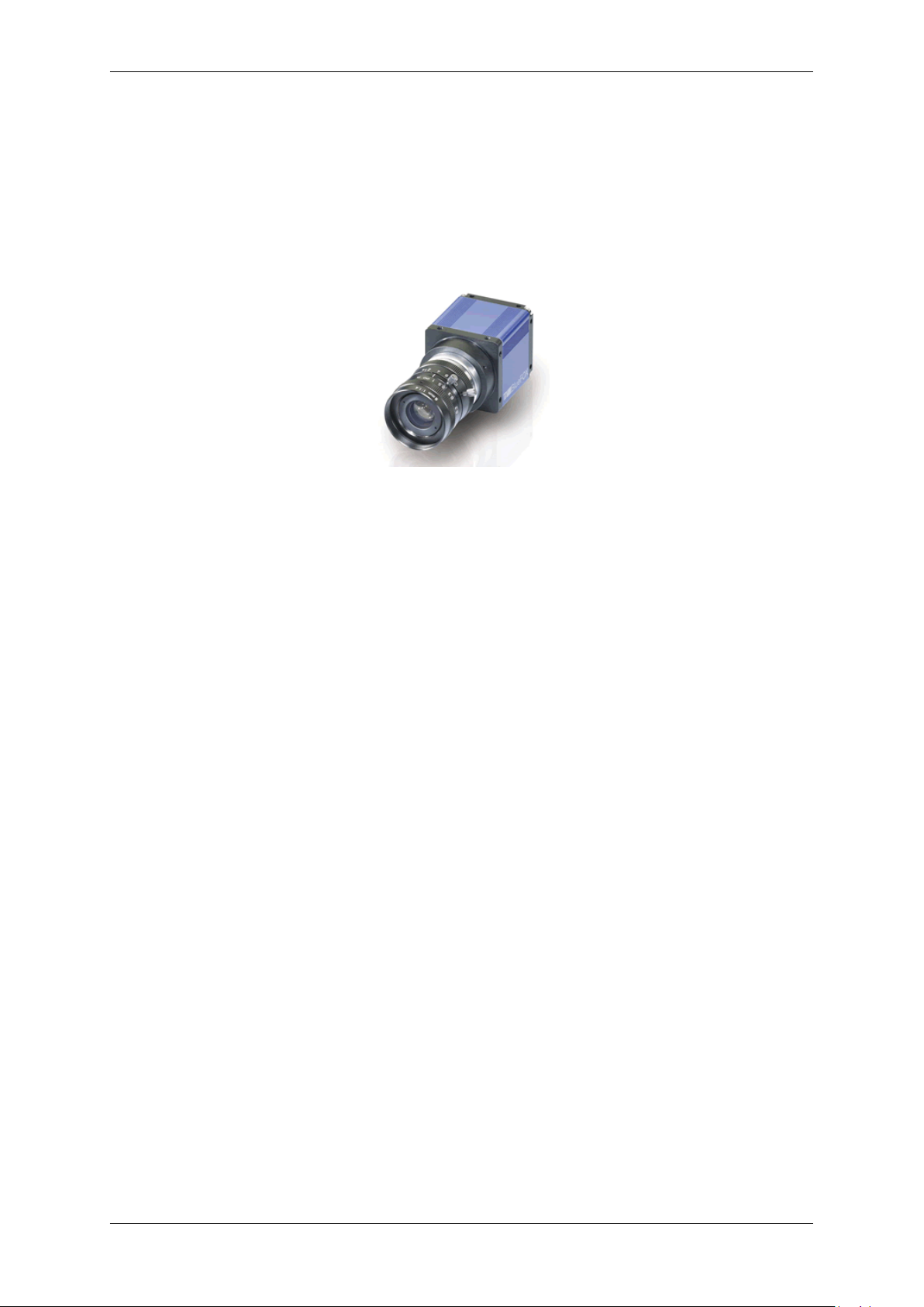
The mvBlueFOX is a compact industrial CCD & CMOS camera solution for any PC with a Hi-Speed USB (USB
2.0) port. A superior image quality makes it suited for most applications. Integrated preprocessing like binning
reduces the PC load to a minimum. The standard Hi-Speed USB interface guarantees an easy integration without
any additional interface board. To make the cameras flexible to any industrial applications, the image processing
tools mvIMPACT as well as different example solutions are available
Figure 1: mvBlueFOX
The mvBlueFOX is suitable for following tasks:
• machine vision
• robotics
• surveillance
• microscopy
• medical imaging
With the name mvBlueFOX-M1xx, the industrial camera mvBlueFOX is also available as a single-board version.
6.1 Order code nomenclature
6.2 mvBlueFOX
The mvBlueFOX nomenclature scheme is as follows:
mvBlueFOX - A B - (1) (2) (3) (4)
- A: Sensor model
220: 0.3 Mpix, 640 x 480, 1/4", CCD
220a: 0.3 Mpix, 640 x 480, 1/3", CCD
200w: 0.4 Mpix, 752 x 480, 1/3", CMOS
221: 0.8 Mpix, 1024 x 768, 1/3", CCD
202a: 1.3 Mpix, 1280 x 1024, 1/2", CMOS
223: 1.4 Mpix, 1360 x 1024, 1/2", CCD
224: 1.9 Mpix, 1600 x 1200, 1/1.8", CCD
205: 5.0 Mpix, 2592 x 1944, 1/2.5", CMOS
- B: Sensor color
G: Gray scale version
C: Color version
- (1): Lensholder
1: C-mount with adjustable backfocus (standard)
MATRIX VISION GmbH
Page 27

20 CONTENTS
2: CS-mount with adjustable backfocus
3: S-mount
- (2): Filter
1: IR-CUT (standard)
2: Glass
3: Daylight cut
9: None
- (3): Case
1: Color blue (standard)
2: Color black, no logo, no label MATRIX VISION
3: Color blue, no logo, no label MATRIX VISION
9: None
- (4): Misc
1: None (standard)
6.3 mvBlueFOX-M
The mvBlueFOX-M nomenclature scheme is as follows:
mvBlueFOX-M A B - (1) (2) (3) (4)
- A: Sensor model
220: 0.3 Mpix, 640 x 480, 1/4", CCD
220a: 0.3 Mpix, 640 x 480, 1/3", CCD
200w: 0.4 Mpix, 752 x 480, 1/3", CMOS
221: 0.8 Mpix, 1024 x 768, 1/3", CCD
202a: 1.3 Mpix, 1280 x 1024, 1/2", CMOS
223: 1.4 Mpix, 1360 x 1024, 1/2", CCD
224: 1.9 Mpix, 1600 x 1200, 1/1.8", CCD
205: 5.0 Mpix, 2592 x 1944, 1/2.5", CMOS
- B: Sensor color
G: Gray scale version
C: Color version
- (1): Lensholder
1: No holder (standard)
2: C-mount with adjustable backfocus
3: CS-mount with adjustable backfocus
4: S-mount #9031
5: S-mount #9033
- (2): Filter
1: None (standard)
2: IR-CUT
3: Glass
4: Daylight cut
- (3): Misc
1: None (standard)
- (4): Misc
1: None (standard)
6.4 mvBlueFOX-IGC
The mvBlueFOX-IGC nomenclature scheme is as follows:
mvBlueFOX-IGC A B - (1) (2) (3) (4)
- A: Sensor model
200w: 0.4 Mpix, 752 x 480, 1/3", CMOS
202b: 1.2 Mpix, 1280 x 960, 1/3", CMOS
202d: 1.2 Mpix, 1280 x 960, 1/3", CMOS
202a: 1.3 Mpix, 1280 x 1024, 1/2", CMOS
205: 5.0 Mpix, 2592 x 1944, 1/2.5", CMOS
- B: Sensor color
G: Gray scale version
C: Color version
MATRIX VISION GmbH
Page 28

6.5 mvBlueFOX-MLC 21
- (1): Lensholder
1: CS-mount without adjustable backfocus (standard)
2: C-mount without adjustable backfocus (CS-mount with add. 5 mm extension ring)
3: C-mount with adjustable backfocus
- (2): Filter
1: IR-CUT (standard)
2: Glass
3: Daylight cut
4: none
- (3): Case
1: Color blue (standard)
2: Color black, no logo, no label MATRIX VISION
9: None
- (4): I/O
1: None (standard)
2: With I/O #08727
6.5 mvBlueFOX-MLC
The mvBlueFOX-MLC nomenclature scheme is as follows:
mvBlueFOX-MLC A B - C D E - (1) (2) (3) (4)
- A: Sensor model
200w: 0.4 Mpix, 752 x 480, 1/3", CMOS
202b: 1.2 Mpix, 1280 x 960, 1/3", CMOS
202d: 1.2 Mpix, 1280 x 960, 1/3", CMOS
202a: 1.3 Mpix, 1280 x 1024, 1/2", CMOS
205: 5.0 Mpix, 2592 x 1944, 1/2.5", CMOS
- B: Sensor color
G: Gray scale version
C: Color version
- C: Mini USB
U: with Mini USB (standard)
X: without Mini USB
- D: Digital I/Os
O: 1x IN + 1x OUT opto-isolated (standard)
T: 2x TTL IN + 2x TTL OUT
L: 3x LVTTL IN
- E: Connector
W: board-to-wire (standard)
B: board-to-board
- (1): Lensholder
1: No holder (standard)
2: C-mount with adjustable backfocus (CS-mount with add. 5 mm extension ring)
3: CS-mount with adjustable backfocus
4: C-mount without adjustable backfocus
5: CS-mount without adjustable backfocus
6: LENSHOLDER SH01F08V3 #09851
7: LENSHOLDER SH02M13V2 #09951
8: LENSHOLDER SH03H16V2 #09850
- (2): Filter
1: None (standard)
2: IR-CUT
3: Glass
4: Daylight cut
- (3): Misc
1: None (standard)
- (4): Misc
1: None (standard)
Examples:
MATRIX VISION GmbH
Page 29

22 CONTENTS
mvBlueFOX-120G
mvBlueFOX-102C
mvBlueFOX-M121C
1
1
1
640 x 480, CCD 1/4", gray
1280 x 1024, CMOS 1/2", color
1024 x 768, CCD 1/3", color, module
mvBlueFOX-MLC200wC-XOW-5111 752 x 480, CMOS 1/3", color, single-board, without Mini-USB, 1x IN +
1x OUT opto-isolated, board-to-wire, CS-mount (w/o backfocus adjustment)
1
: -1111 is the standard delivery variant and for this reason it is not mentioned.
6.6 What's inside and accessories
Due to the varying fields of application the mvBlueFOX is shipped without accessories. The package contents:
• mvBlueFOX
• mvIMPACT CD-ROM or DVD-ROM with example application and manual
• instruction leaflet
For the first use of the mvBlueFOX we recommend the following accessories to get the camera up and running:
• A USB 2.0 cable
Attention
According to the customer and if the mvBlueFOX-MLC is shipped without lensholder, the mvBlueFOX-MLC
will be shipped with a protective foil on the sensor. Before usage, please remove this foil!
Accessories for the mvBlueFOX:
Part code Description
ADAPTER CS-MOUNT Lens fixing for mvBlueFOX to match with CS-mount lenses
KS-USB2-AA-EXT 05.0 USB 2.0 extension, activeUSB2 A plug to USB2 A jack, length 5m
KS-USB2-AB 03.0 TR USB 2.0 cable A-B, transparent, Profi Line. Length 3m
KS-USB2-B4ST 02.0 USB 2.0 cable for mvBlueFOX, Binder 4pol to USB2-A. Length: 2m
KS-USB2-B4ST 03.0 USB 2.0 cable for mvBlueFOX, Binder 4pol to USB2-A. Length: 3m
KS-USB2-B4ST 05.0 USB 2.0 cable for mvBlueFOX, Binder 4pol to USB2-A. Length: 5m
KS-USB2-PHR4 01.5 USB connector cable for mvBlueFOX-M1xx. Length: 1.5m
KS-PHR12 500 Cable for mvBlueFOX-M1xx dig. I/O, 12-pin. Length: 500mm
1..4 brown
5..8 gray
9 red
10 black
11 yellow
12 black
KS-MLC-IO-TTL 00.5 mvBlueFOX-MLC board-to-board TTL IO cable for master-slave synchroniza-
tion (Molex plug to Molex plug), Length: 0.5m
MATRIX VISION GmbH
Page 30

6.6 What's inside and accessories 23
KS-MLC-IO-W mvBlueFOX-MLC board-to-wire I/O data cable, Molex 0510211200 with crimp
terminal 50058. Length: up to 1m
KS-MLC-USB2-IO-W mvBlueFOX-MLC board-to-wire I/O data and USB 2.0 cable, Molex
0510211200 with crimp terminal 50058 to USB2-A. Length: up to 1m
MV-Lensholder BFM-C C-mount lensholder for mvBlueFOX-M,incl. IR-Cut filter
MV-Lensholder BFM-S 9031 S-mount lensholder M12 x 0,5 type MS-9031 for mvBlueFOX-M102
MV-Lensholder BFM-S 9033 S-mount lensholder M12 x 0,5 type: MS-9033 for mvBlueFOX-M102
MV-LENSHOLDER SH02M13 S-mount lensholder M12 x 0.5, height 13mm for mvBlueFOX-MLC
MV-LENSHOLDER SH01F08 S-mount lensholder M12 x 0.5, height 8mm for mvBlueFOX-MLC
ADAPTER S-C AD01S Adapter for S-mount lens (M12x0,5) to C-mount, high penetration depth for
mvBlueFOX-IGC
ADAPTER S-C AD02F Adapter for S-mount lens (M12x0,5) to CS-mount, penetration depth: 5.5mm,
outside diameters: 31mm for mvBlueFOX-IGC
MV-Tripod Adapter BF Tripod adapter for mvBlueFOX
MATRIX VISION GmbH
Page 31

24 CONTENTS
7 Quickstart
7.1 Windows
7.1.1 System Requirements
Currently supported Windows versions are:
• Microsoft Windows 7 (32-bit, 64-bit)
• Microsoft Windows 8.1 (32-bit, 64-bit)
• Microsoft Windows 10 (32-bit, 64-bit)
Other Windows version can be used at the user's own risk.
Note
Since mvIMPACT Acquire version 2.8.0 it could be possible that you have to update your Windows installer at
least using Windows XP. The necessary packages are available from Microsoft's website: http://www.←-
microsoft.com/en-US/download/details.aspx?id=8483
All necessary drivers for Windows are contained in the standard mvIMPACT CD-ROM or DVD-ROM. For newer
driver versions we recommend to visit the MATRIX VISION website at www.matrix-vision.de, section "Products
-> Cameras -> your interface -> your product -> Downloads".
Note
For Windows XP Embedded
As mvBlueFOX cameras will register as an 'imaging device' in the systems device manager please make
sure that your Windows XP Embedded (XPe) distribution is shipped/build with support for the corresponding
device class ("Class GUID {6bdd1fc6-810f-11d0-bec7-08002be2092f}") before installing
the mvBlueFOX device driver. Otherwise, an installing of the driver when connecting a camera will fail with an
error message like "a required section in the INF file could not be found". The camera will not be accessible
then.
The mvBlueFOX is a USB 2.0 compliant camera device and needs therefore a functioning USB 2.0 port. If you are
not sure about this, please follow these steps:
1. Press "Start" and click on "Run"
2. Enter
msinfo32
3. Click on "Components" and look after "USB"
4. If there is a entry like "USB 2.0 Root Hub" or "ROOT_HUB20", your system has USB 2.0.
Please be sure that your system has at least one free USB port.
MATRIX VISION GmbH
Page 32

7.1 Windows 25
7.1.2 Installing the mvIMPACT Acquire driver
Warning
Before connecting the mvBlueFOX, please install the software and driver first!
To install the software and driver insert the mvIMPACT CD-ROM or DVD-ROM into your CD drive or download the
latest driver from our website: https://www.matrix-vision.com "Products -> Hardware ->
mvBlueFOX -> Downloads Tab".
By double clicking on "mvBlueFOX-x86-n.n.n.msi" (for 32-bit systems) or "mvBlueFOX-x86_64-n.n.n.msi" (for
64-bit systems), the mvBlueFOX installer will start automatically.
Figure 1: mvBlueFOX installer - Start window
Select the folder, where you want to install the software.
MATRIX VISION GmbH
Figure 2: mvBlueFOX installer - Select folder
Page 33

26 CONTENTS
Select the features you want to install. Following features exist:
• "Base Libraries"
This feature contains all necessary files for property handling and display. Therefore, it is not selectable.
• "mvBlueFOX driver"
This is also not selectable.
• "Tools"
This feature contains tools for the mvBlueFOX (e.g. to configure MATRIX VISION devices (mvDevice←-
Configure) or to acquire images (wxPropView)).
• "Developer API"
The Developer API" contains the header for own programming. Additionally you can choose the examples,
which installs the sources of wxPropView and three mini samples. The project files of the mini samples are
for Visual C++ 7, Visual C++ 6 and Borland C Builder 6. The wxPropView project exists only for Visual C++
7. - \b "Documentation"
This will install this mvBlueFOX manual a single HTML help file (.chm).
Figure 3: mvBlueFOX installer - Select features
Confirm the installation by clicking "Next".
MATRIX VISION GmbH
Page 34

7.1 Windows 27
Figure 4: mvBlueFOX installer - Confirm installation
The installation is finished now you can close the window.
Figure 5: mvBlueFOX installer - Finished installation
7.1.3 Installing the hardware
Warning
Before connecting the mvBlueFOX, please install the software and driver first!
It is not necessary to shutdown your system. On an USB port, it is possible to hot plug any USB device (hot plug
lets you plug in new devices and use them immediately).
MATRIX VISION GmbH
Page 35

28 CONTENTS
Warning
If using the Binder connector first connect the cable to the camera, then connect the camera to the PC.
Plug the mvBlueFOX to an USB 2.0 Port. After plugging the mvBlueFOX Windows® shows "Found New Hardware"
and starts the Windows Hardware Wizard.
Figure 6: Windows - Found new hardware
The Wizard asks you for the driver. The installation doesn't need any Windows® automatic at this step and it is
recommended to type the driver directory by hand. Choose "No, not this time" and press "Next".
Figure 7: Windows Hardware Wizard - Driver Installation
Choose "Install the software automatically" and press "Next".
MATRIX VISION GmbH
Page 36

7.1 Windows 29
Figure 8: Windows Hardware Wizard - Driver location
The Hardware Wizard installs the driver.
Figure 9: Windows Hardware Wizard - Driver location
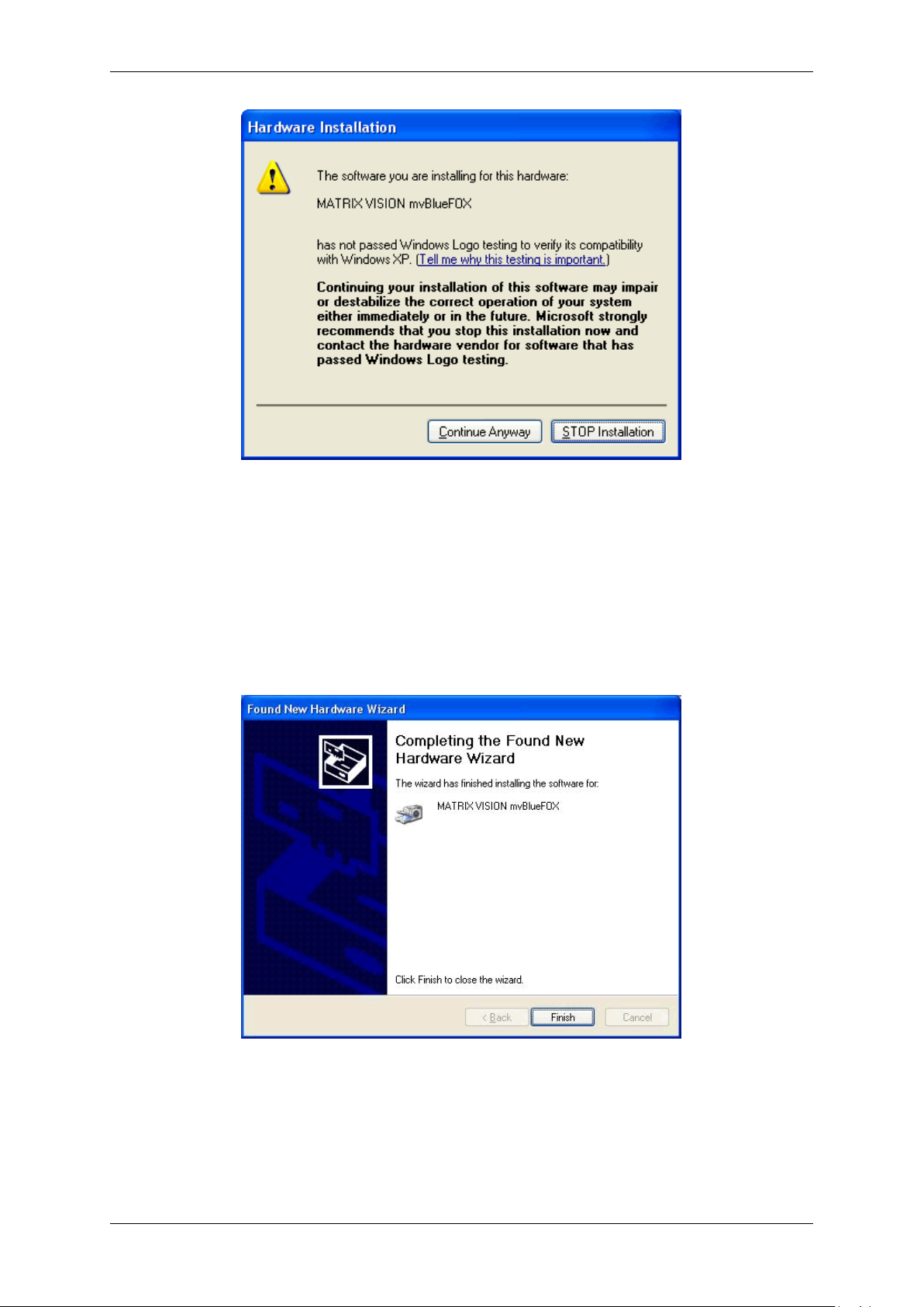
The Hardware Wizard will search the registry for the device identification and after a while the Wizard prompts you
to continue the installation or to abort it. Also Windows® will display the following message to inform the user that
this driver digitally signed by Microsoft. You have to select 'Continue anyway' otherwise, the driver can't be installed.
If you don't want to install a driver that is not signed you must stop the installation but can't work with the mvBlueFOX
camera then.
Press "Continue Anyway" and finish the driver installation.
MATRIX VISION GmbH
Page 37
30 CONTENTS
Figure 10: Windows Hardware Wizard - Windows logo testing
After the Windows® Logo testing, you have to click "Finish" to complete the installation.
Figure 11: Windows Hardware Wizard - Complete the installation
Now, you can find the installed mvBlueFOX in the Windows® "Device Manager" under image devices.
MATRIX VISION GmbH
Page 38

7.2 Linux 31
Figure 12: Windows Device Manager - Installed mvBlueFOX
After this installation, you can acquire images with the mvBlueFOX. Simply start the application wxPropView (p. 77)
(wxPropView.exe) from
mvBlueFOX/bin.
See also
wxPropView (p.77)
7.2 Linux
7.2.1 System Requirements
Kernel requirements
Kernel 2.6.x .. Kernel 3.x.x.
• usbfs support (CONFIG_USB_DEVICEFS)
Note
This is different from devfs! support. The USB device file system should, of course, be mounted at
/proc/bus/usb.
• SysV IPC support (CONFIG_SYSVIPC).
Note
Most distributions will have these kernel options turned on by default.
MATRIX VISION GmbH
Page 39

32 CONTENTS
7.2.1.1 Software requirements
• Linux x86 (32-bit)
– The 32 bit version will run on a 64-bit Linux system if the other library requirements are met with 32-bit
libraries. I.e. you cannot mix 64 and 32-bit libraries and applications.
– Versions for Linux on x86-64 (64-bit), PowerPC, ARM or MIPS may be possible on request.
• GNU compiler version GCC 3.2.x or greater and associated tool chain.
Note
Our own modified version of libusb has been statically linked to our library and is therefore included, so
libusb is not a requirement.
7.2.1.2 Other requirements
• libexpat (http://expat.sourceforge.net)
• Optional: wxWidgets 2.6.x (non Unicode) for the wxWidget test programs.
• Optional: udev or hotplug subsystem (see also 4. below).
As an example of which packets need to be installed, consider OpenSuSE 10.1:
• The compiler used is gcc 4.1.0 and may need to be installed. Use the "gcc" und "gcc-c++" RPMs. Other
RPMs may be installed automatically due to dependencies (e.g. make).
• libexpat will almost definitely be installed already in any software configuration. The RPM is called "expat".
• Install the wxWidgets "wxGTK" and "wxGTK-develop" RPMs. Others that will be automatically installed due
to dependencies include "wxGTK-compat" and "wxGTK-gl". Although the MATRIX VISION software does not
use the ODBC database API the SuSE version of wxWidgets has been compiled with ODBC support and the
RPM does not contain a dependency to automatically install ODBC. For this reason you must also install the
"unixODBC-devel" RPM.
• OpenSuSE 10.1 uses the udev system so a separate hotplug installation is not needed.
7.2.1.3 Hardware requirements
USB 2.0 Host controller (Hi-Speed) or USB 1.1 Host controller will also work (with a max. frame rate of 3 to 4 fps
at 640x480 only).
Note
We have noticed problems with some USB chip sets. At high data rates sometimes the image data appears
to be corrupted. If you experience this you could try one or more of the following things.
• a different PC.
• a plug-in PCI/USB-2.0 card without any cables between the card and the USB connector.
• turning off the image footer property - this will ignore data errors.
Note
The driver contains libraries for Linux x86 (32 bit) or Linux 64-bit (x86_64). There are separate package files
for systems with tool chains based on GNU gcc 3.2.x - 3.3.x and those based on GNU gcc >= 3.4.x. gcc 3.1.x
may work but, in general, the older your tool chain is, the lass likely it is that it will work. Tool chains based on
GNU gcc 2.x.x are not supported at all.
GCC 4.x (4.1.0) has been tested on OpenSuSE 10.1 and should work on other platforms.
This version (32-bit only) will also run in a VMware (http://www.vmware.com) virtual machine!
MATRIX VISION GmbH
Page 40

7.2 Linux 33
7.2.2 Installing the mvIMPACT Acquire driver
To use the mvBlueFOX camera within Linux (grab images from it and change its settings), a driver is needed,
consisting of several libraries and several configuration files. These files are required during run time.
To develop applications that can use the mvBlueFOX camera, a source tree is needed, containing header files,
makefiles, samples, and a few libraries. These files are required at compile time.
Both file collections are distributed in a single package:
mvBlueFOX-x86_ABI2-n.n.n.tgz
1. Please start a console and change into a directory e.g. /home/username/workspace
cd /home/username/workspace
2. Copy the install script (available as download from https://www.matrix-vision.com) and the
hardware driver to the workspace directory (e.g. from a driver CD or from the website):
~/workspace$ cp /media/cdrom/drv/Linux/install_mvBlueFOX.sh /
. && cp /media/cdrom/drv/Linux/mvBlueFOX-x86_ABI2-1.12.45.tgz -t ./
3. Run the install script:
~/workspace$ ./install_mvBlueFOX.sh
Note
The install script has to be executable. So please check the rights of the file.
During installation, the script will ask, if it should build all tools and samples.
You may need to enable the execute flag with
chmod a+x install_mvBlueFOX.sh.
The installation script checks the different packages and installs them with the respective standard packages manager (apt-get) if necessary.
Note
The installation script ("install_mvBlueFOX.sh") and the archive ("mvBlueFOX-x86_ABI2-n.←-
n.n.tgz") must reside in the same directory. Nothing is written to this directory during script execution, so
no write access to the directory is needed in order to execute the script.
You need Internet access in case one or more of the packages on which the GenICam™ libs depend are not yet
installed on your system. In this case, the script will install these packages, and for that, Internet access is required.
The script takes two arguments, both of which are optional:
1. target directory name
2. version
The target directory name specifies where to place the driver. If the directory does not yet exist, it will be created.
The path can be either absolute or relative; i.e. the name may but need not start with "/.".
MATRIX VISION GmbH
Page 41

34 CONTENTS
Note
This directory is only used for the files that are run time required.
The files required at compile time are always installed in "$HOME/mvimpact-acquire-n.n.n". The script
also creates a convenient softlink to this directory:
mvimpact-acquire -> mvIMPACT_acquire-1.12.45
If this argument is not specified, or is ".", the driver will be placed in the current working directory.
The version argument is entirely optional. If no version is specified, the most recent mvBlueFOX-x86_AB←-
I2-n.n.n.tgz found in the current directory will be installed.
You can now start wxPropView (p. 77), after installing the hardware (p. 39) like
wxPropView
because the installer script added the needed symbolic links.
Note
If you want to install the mvBlueFOX Linux driver without installer script manually, please have a look at the
following chapter:
7.2.2.1 Installing the mvIMPACT Acquire driver manually
Note
We recommend to use the installer script to install the mvBlueFOX driver (p. 33).
The mvBlueFOX is controlled by a number of user-space libraries. It is not necessary to compile kernel modules for
the mvBlueFOX.
1. Logon to the PC as the "root" user or start a super user session with "su". Start a console with "root"
privileges.
2. Determine which package you need by issuing the following command in a terminal window:
gcc -v
This will display a lot of information about the GNU gcc compiler being used on your system. In case of the
version number you have to do following:
Version Description
2.x.x (obsolete) You cannot use the mvBlueFOX on your computer. Upgrade to a newer distribution.
3.2.x or 3.3.x (obsolete) Use the C++ ABI 1. This package has ABI1 in its name.
3.4.x or 4.x.x Use the C++ ABI 2. This package has ABI2 in its name.
MATRIX VISION GmbH
Page 42

7.2 Linux 35
3. You can now install the mvBlueFOX libraries as follows:
• create a new directory somewhere on your system.
• copy the correct mvbluefox package file to this directory and change into this directory with "cd".
The mvBlueFOX libraries are supplied as a "tgz" archive with the extension ".tgz". The older
"autopackage" format is now deprecated since it cannot handle 64-bit libraries.
(a) Unpack the archive using "tar" e.g.:
tar xvzf mvBlueFOX-x86_ABI2-1.12.45.tgz
Note
Current versions of the ABI1 libraries were compiled using a SuSE 8.1 system for maximum compatibility with older Linux distributions. These libraries should work with all SuSE 8.x and SuSE
9.x versions as well as with Debian Sarge and older Red Hat / Fedora variants.
Current versions of the ABI2 libraries were compiled using a SuSE 10.1 system for maximum
compatibility with newer Linux distributions. These libraries should work with SuSE 10.x as well
as with Ubuntu 6.06 or newer, with up-to-date Gentoo or Fedora FC5.
(b) After installing the mvBlueFOX access libraries you will see something like the following directory struc-
ture in your directory (dates and file sizes will differ from the list below):
drwxr-xr-x 10 root root 4096 Jan 5 15:08 .
drwxr-xr-x 23 root root 4096 Jan 4 16:33 ..
drwxr-xr-x 3 root root 4096 Jan 5 15:08 DriverBase
-rw-r--r-- 1 root root 1079 Jan 5 15:08 Makefile
drwxr-xr-x 7 root root 4096 Jan 5 15:08 apps
drwxr-xr-x 4 root root 4096 Jan 5 15:08 common
drwxr-xr-x 3 root root 4096 Jan 5 15:08 lib
drwxr-xr-x 3 root root 4096 Jan 5 15:08 mvDeviceManager
drwxr-xr-x 2 root root 4096 Jan 5 15:08 mvIMPACT_CPP
drwxr-xr-x 3 root root 4096 Jan 5 15:08 mvPropHandling
drwxr-xr-x 1 root root 4096 Jan 5 15:08 scripts
The directory "lib/x86" contains the pre-compiled 32-bit libraries for accessing the mvBlueFOX.
If 64-bit libraries are supplied, they will be found in "lib/x86_64". The "apps" directory contains test
applications (source code). The other directories contain headers needed to write applications for the
mvBlueFOX.
Since the libraries are not installed to a directory known to the system i.e. not in the "ldconfig"
cache you will need to tell the system where to find them by...
• using the "LD_LIBRARY_PATH" environment variable,
• or copying the libraries by hand to a system directory like "/usr/lib" (or using some symbolic
links),
• or entering the directory in "/etc/ld.so.conf" and running "ldconfig".
e.g. to start the application called "LiveSnap":
Note
Please declare the device e.g. BF∗ or BF00001
cd my_mvbf_directory
LD_LIBRARY_PATH=‘pwd‘/lib/x86 apps/LiveSnap/x86/LiveSnap BF
For 64-bit it will look like this...
LD_LIBRARY_PATH=‘pwd‘/lib/x86_64 apps/LiveSnap/x86_64/LiveSnap BF
For ARM it will look like this...
LD_LIBRARY_PATH=‘pwd‘/lib/arm apps/LiveSnap/arm/LiveSnap BF
*
*
*
etc.
After installing the libraries and headers you may continue with "3." below as a normal user i.e. you do
not need to be "root" in order to compile the test applications. See also the note "4." below.
(c) To build the test applications type "make". This will attempt to build all the test applications contained
in "apps". If you have problems compiling the wxWidget library or application you may need to do one
or more of the following:
MATRIX VISION GmbH
Page 43

36 CONTENTS
• install the wxWidget 3.x development files (headers etc.) supplied for your distribution. (See "Other
requirements" above).
• fetch, compile and install the wxWidget 3.x packet from source downloaded from the website
(http://www.wxwidgets.org).
• alter the Makefiles so as to find the wxWidget configuration script called wx-config.
The files you may need to alter are to be found here:
apps/mvPropView/Makefile.inc
You will find the compiled test programs in the subdirectories "apps/.../x86". For 64 bit systems
it will be "apps/.../x86_64". For ARM systems it will be "apps/.../arm".
If you cannot build the wxWidget test program you should, at least, be able to compile the text-based
test programs in apps/SingleSnap, apps/LiveSnap, etc.
(d) It may be possible to run applications as a non-root user on your system if you are using the udev
system or a fairly recent version of hotplug.
7.2.2.2 For udev (e.g. Gentoo∗, OpenSuSE 10.0 - 10.1)
Add the following 2 rules to one of the files in the directory "/etc/udev/rules.d" or make a new file in this
directory (e.g. "/etc/udev/rules.d/20-mvbf.rules") containing the lines below:
ENV{UDEVD_EVENT}=="1", ACTION=="add", BUS=="usb", ENV{PRODUCT}=="164c/101/0", /
RUN+="/bin/sh -c ’chmod 0664 $env{DEVICE}; chgrp usb $env{DEVICE}’"
ENV{UDEVD_EVENT}=="1", ACTION=="add", BUS=="usb", ENV{PRODUCT}=="164c/103/0", /
RUN+="/bin/sh -c ’chmod 0664 $env{DEVICE}; chgrp usb $env{DEVICE}’"
You will find an example file "20-mvbf.rules" in the scripts directory after installation.
Note
Do not forget to add your user to the usb group! You may have to create the group first.
Current Gentoo systems support udev with a minimal, legacy hotplug system. It is usually sufficient to add any
usernames that are to be used for the mvBlueFOX to the group "usb" because there is already a udev rule giving
write permission to all USB devices to members of this group. If this does not work then try the other alternatives
described here. The udev method is better because hotplug is likely to be removed eventually.
7.2.2.3 For udev (OpenSuSE 10.2 - 10.x)
In "/etc/fstab" in the line starting with usbfs change noauto to defaults
Afterwards either restart the system or execute "mount -a"
In "/etc/udev/rules.d/50-udev-default.rules" (or similar) change the line after a comment regarding libusb. Change 'MODE="0644"' in 'MODE="0664", GROUP="users"'
Connect the camera to the system now or re-connect it if it has been connected already
In case the environment variable USB_DEVFS_PATH is not set, it needs to be set to "/dev/bus/usb" ('export US←-
B_DEVFS_PATH="/dev/bus/usb"'.
MATRIX VISION GmbH
Page 44

7.2 Linux 37
7.2.2.4 For udev on Ubuntu 06.10
Edit the file /etc/udev/rules.d/40-permissions.rules. Search for the entry for usbfs. It should look like this:
# USB devices (usbfs replacement)
SUBSYSTEM="usb_device" MODE="0664"
Now change it to read like this:
# USB devices (usbfs replacement)
SUBSYSTEM="usb_device" GROUP="plugdev", MODE="0664"
7.2.2.5 udev on some other systems
Some very up-to-date systems also set the environment variable $USB_DEVFS_PATH to point to "/dev/bus/usb"
instead of the older (default) value of "/proc/bus/usb". This may cause the mvBlueFOX libraries to attempt
to access device nodes in "dev/bus/usb" but the rules described above will not change the permissions on
these files. Normally you will find a rule in "/etc/udev/rules.d/50-udev.rules" which will already cure
this problem. You might like to slightly modify this rule to give write permission to a specific group e.g. the group
"usb". A patch is supplied in the scripts directory to do this.
7.2.2.6 Alternatively, for a system with full hotplugging (e.g. older SuSE systems)
Copy the files named below from the scripts directory into the directory "/etc/hotplug/usb":
matrixvision.usermap
matrixvision_config
The file "matrixvision.usermap" contains the vendor and product IDs for the mvBlueFOX cameras and
specifies that the script "matrixvision_config" should be run when a MATRIX VISION mvBluefOX camera is plugged in or out. This script attempts to write some information to the system log and then changes the
permissions for the newly-created device node so that non-root users can access the camera.
This feature has not yet been extensively tested. If you find that the applications start but appear to hang or to wait
for a long time before continuing (and normally crashing) then changing the file permissions on your system does
not appear to be sufficient. We have observed this on a 32 bit SuSE 9.1 system. In this case you may have more
success if you change the owner of the application to "root" and set the suid bit to allow it to run with "root"
permissions.
Note
This is considered a security risk by some experts.
If you have been using the mvBlueFOX with one user (e.g. root) and want to try it as another user you should
remove the complete directory "/tmp/mv/", which may contain several files of zero length. These files are
used to control mutexes within the software and will be owned by the first user. The new user will probably not
be able to write to these files and the mvBlueFOX will not work.
7.2.2.6.1 Using CMOS versions of the mvBlueFOX and mvBlueFOX-M especially with USB 1.1
Version 1.4.5 contains initial support for CMOS mvBlueFOX on USB 1.1 . In order to conform to the rigid timing
specifications of the CMOS sensor, onboard RAM is used. This RAM is available only on mvBlueFOX-M boards at
the moment. Therefore you cannot use the mvBlueFOX-102x with USB 1.1 . It will work with USB 2.0.
Note
If you want to capture continuous live images from mvBlueFOX-102 or mvBlueFOX-M102x you should switch
the trigger mode from "Continuous" to "OnDemand" for best reliable results. For single snaps the default
values should work correctly.
MATRIX VISION GmbH
Page 45

38 CONTENTS
7.2.2.6.2 Power Down Mode
To try out the new power down mode you will need to update the firmware on the mvBlueFOX to at least version
39. There is a simple text-based utility to do this in "apps/FirmwareUpgrade". Just build the application and
start on the platform of your choice giving the serial number of the connected mvBlueFOX as a parameter. E.g. on
an Embedded ARM system:
$ ./arm/FirmwareUpgrade BF000188
++ Start FirmwareUpgrade: Sep 28 2006/11:48:19
Have found 1 devices on this platform!
0 Serial: BF000188
Initialising the device: BF000188. This might take some time...
The firmware of device BF000188 is currently 37.
It will now be updated. During this time(approx. 30 sec.) the application
will not react. Please be patient.
Successfully performed firmware update
Update successful.
Please disconnect and reconnect the device now to activate the new firmware.
Press any key to end the application
To test the power down mode use the test application in "apps/PowerDownTest". Take a look at the source
code to see which function is used to switch on power down mode. Here is an example of the output for an
Embedded ARM system:
$ ./arm/PowerDownTest BF000188
++ Start PowerDownTest sample: Sep 28 2006/11:48:43
Have found 1 devices on this platform!
0 Serial: BF000188
Initialising the device: BF000188. This might take some time...
Ready to snap. Press ’p’<return> to power down, ’q’<return> to quit or /
<return> to snap an image..
Request Nr.: 0. Snap took 0.76s.,
Will save the file as: SingCapt.pgm
Ready to snap. Press ’p’<return> to power down, ’q’<return> to quit or /
<return> to snap an image..
Request Nr.: 1. Snap took 0.41s.,
Will save the file as: SingCapt.pgm
Ready to snap. Press ’p’<return> to power down, ’q’<return> to quit or /
<return> to snap an image..
Request Nr.: 2. Snap took 0.4s.,
Will save the file as: SingCapt.pgm
Ready to snap. Press ’p’<return> to power down, ’q’<return> to quit or /
<return> to snap an image..
p
Power off!
Ready to snap. Press ’p’<return> to power down, ’q’<return> to quit or /
<return> to snap an image..
Power On!. Power On took 2.24s.,
Request Nr.: 3. Snap took 0.58s.,
Will save the file as: SingCapt.pgm
Ready to snap. Press ’p’<return> to power down, ’q’<return> to quit or /
<return> to snap an image..
Request Nr.: 0. Snap took 0.39s.,
Will save the file as: SingCapt.pgm
Ready to snap. Press ’p’<return> to power down, ’q’<return> to quit or /
<return> to snap an image..
q
If the mvIMPACT_Acquire API makes references to Windows DLLs please use the equivalent Linux dynamic libraries that have been installed on your system.
MATRIX VISION GmbH
Page 46

7.3 Relationship between driver, firmware and FPGA file 39
7.2.3 Installing the hardware
Warning
If using the Binder connector first connect the cable to the camera, then connect the camera to the PC.
The driver for Linux does not include hot-plugging support at the application level. I.e. a running application will not
be informed of new mvBlueFOX devices that have been plugged in and will probably crash if an mvBlueFOX camera
is unplugged whilst it is being used. You need to stop the application, plug in the new camera and then restart the
application. This will change in a later version.
7.3 Relationship between driver, firmware and FPGA file
To operate a mvBlueFOX device apart from the physical hardware itself 3 pieces of software are needed:
• a firmware running on the device (provides low-level functionality like allowing the device to act as a USB
device, support for multiple power states etc.)
• an FPGA file loaded into the FPGA inside the device (provides access features to control the behaviour of
the image sensor, the digital I/Os etc.)
• a device driver (this is the mvBlueFOX.dll on Windows® and the libmvBlueFOX.so on Linux) running on the
host system (provides control over the device from an application running on the host system)
The physical mvBlueFOX device has a firmware programmed into the device's non-volatile memory, thus allowing
the device to act as a USB device by just connecting the device to a free USB port. So the firmware version that will
be used when operating the device does NOT depend on the driver version that is used to communicate with the
device.
On the contrary the FPGA file version that will be used will be downloaded in volatile memory (RAM) when accessing
the device through the device driver thus the API. One or more FPGA files are a binary part of the device driver.
This shall be illustrated by the following figure:
Figure 13: The firmware file is a binary part of the device driver
Note
As it can be seen in the image a single firmware file is also a binary part of the device driver. However it
is important to notice that this firmware file will NOT be used automatically but only when the user or an
application explicitly updates the firmware on the device and will only become active after power-cycling the
device.
MATRIX VISION GmbH
Page 47

40 CONTENTS
7.3.1 FPGA
Until the device gets initialized using the API no FPGA file is loaded in the FPGA on the device. Only by opening
the device through the API the FPGA file gets downloaded and only then the device will be fully operational:
Figure 14: The FPGA file gets downloaded when the device will be opened through the API
As the FPGA file will be stored in RAM, disconnecting or closing the device will cause the FPGA file to be lost. The
firmware however will remain:
Figure 15: The FPGA file will be lost if the device is disconnected or closed
In case multiple FPGA files are available for a certain device the FPGA file that shall be downloaded can be selected
by an application by changing the value of the property Device/CustomFPGAFileSelector. However the value of this
property is only evaluated when the device is either initialized using the corresponding API function OR if a device
has been unplugged or power-cycled while the driver connection remains open and the device is then plugged back
in.
Note
There is just a limited set of devices that offer more than one FPGA file and these additional FPGA files serve
very special purposes so in almost every situation the default FPGA file will be the one used by an application.
Before using custom FPGA files, please check with MATRIX VISION about why and if this makes sense for
your application.
So assuming the value of the property Device/CustomFPGAFileSelector has been modified while the device has
been unplugged, a different FPGA file will be downloaded once the device is plugged back into the host system:
Figure 16: A different FPGA file can be downloaded
MATRIX VISION GmbH
Page 48

7.3 Relationship between driver, firmware and FPGA file 41
7.3.2 Firmware
Only during a firmware update the firmware file that is a binary part of the device driver will be downloaded permanently into the device's non-volatile memory.
Warning
Each device driver just contains one specific firmware version thus once a device's firmware has been updated
using a specific device driver the only way to change the firmware version will be using another device driver
version for upgrading/downgrading the firmware again.
So assume a device with a certain firmware version is connected to a host system:
Figure 17: A certain firmware version is connected to a host system
During an explicit firmware update, the firmware file from inside the driver will be downloaded onto the device. In
order to become active the device must be power-cycled:
Figure 18: Firmware file will be downloaded during an firmware update...
When then re-attaching the device to the host system, the new firmware version will become active:
MATRIX VISION GmbH
Figure 19: ... after repowering the device it will be active
Page 49

42 CONTENTS
• The current firmware version of the device can be obtained either by using one of the applications which
are part of the SDK such as mvDeviceConfigure (p. 116) or by reading the value of the property Device/←-
FirmwareVersion or Info/FirmwareVersion using the API
• The current FPGA file version used by the device can be obtained by reading the value of the property
Info/Camera/SensorFPGAVersion
Using wxPropView the same information is available as indicated by the following figure:
Figure 20: wxPropView - FPGA and Firmware version numbers
7.4 Settings behaviour during startup
A setting contains all the parameters that are needed to prepare and program the device for the image capture.
Every image can be captured with completely different set of parameters. In almost every case, these parameters
are accessible via a property offered by the device driver. A setting e.g. might contain
• the gain to be applied to the analogue to digital conversion process for analogue video sources or
• the AOI to be captured from the incoming image data.
MATRIX VISION GmbH
Page 50
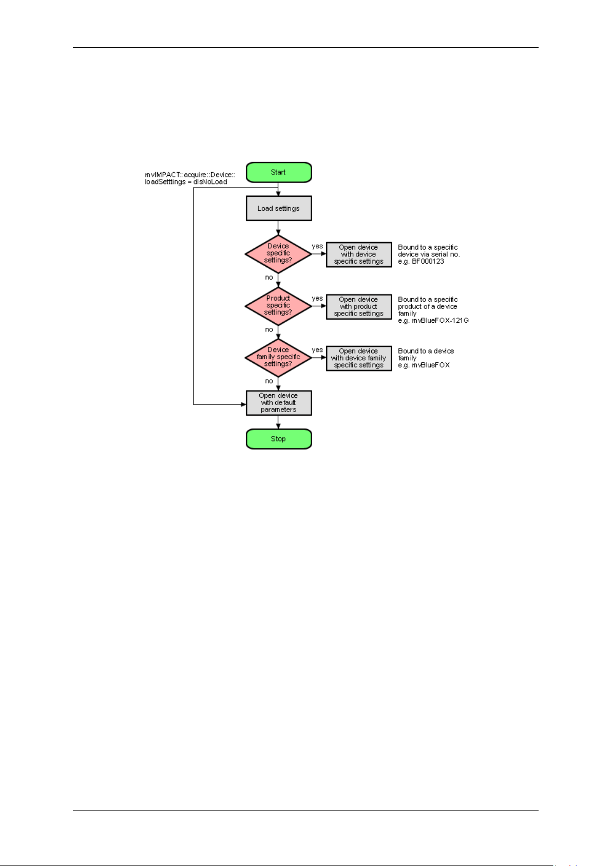
7.4 Settings behaviour during startup 43
So for the user a setting is the one an only place where all the necessary modifications can be applied to achieve
the desired form of data acquisition.
Now, whenever a device is opened, the driver will execute following procedure:
Figure 21: wxPropView - Device setting start procedure
• Please note that each setting location step in the figure from above internally contains two search steps. First
the framework will try to locate a setting with user scope and if this can't be located, the same setting will be
searched with global (system-wide) scope. Under Windows® this e.g. will access either the HKEY_CURR←-
ENT_USER or (in the second step) the HKEY_LOCAL_MACHINE branch in the Registry.
• Whenever storing a product specific setting, the device specific setting of the device used for storing will be
deleted (if existing). E.g. you have a device 'VD000001' which belongs to the product group 'VirtualDevice'
with a setting exclusively for 'VD000001'. As soon as you store a product specific setting, the (device specific)
setting for 'VD000001' will be deleted. Otherwise a product specific setting would never be loaded as a device
specific setting will always be found first.
• The very same thing will also happen when opening a device from any other application! wxPropView (p. 77)
does not behave in a special way but only acts as an arbitrary user application.
• Whenever storing a device family specific setting, the device specific or product specific setting of the device
used for storing will be deleted (if existing). See above to find out why.
• Under Windows® the driver will not look for a matching XML file during start-up automatically as the native
storage location for settings is the Windows® Registry. This must be loaded explicitly by the user by using
the appropriate API function offered by the SDK. However, under Linux XML files are the only setting formats
understood by the driver framework thus here the driver will also look for them at start-up. The device specific
setting will be an XML file with the serial number of the device as the file name, the product specific setting
will be an XML file with the product string as the filename, the device family specific setting will be an XML
file with the device family name as the file name. All other XML files containing settings will be ignored!
MATRIX VISION GmbH
Page 51

44 CONTENTS
• Only the data contained in the lists displayed as "Image Setting", "Digital I/O" and "Device
Specific Data" under wxPropView (p. 77) will be stored in these settings!
• Restoring of settings previously stored works in a similar way. After a device has been opened the settings
will be loaded automatically as described above.
• A detailed description of the individual properties offered by a device will not be provided here but can be
found in the C++ API reference, where descriptions for all properties relevant for the user (grouped together in
classes sorted by topic) can be found. As wxPropView (p.77) doesn't introduce new functionality but simply
evaluates the list of features offered by the device driver and lists them any modification made using the GUI
controls just calls the underlying function needed to write to the selected component. wxPropView (p. 77)
also doesn't know about the type of component or e.g. the list of allowed values for a property. This again is
information delivered by the driver and therefore can be queried by the user as well without the need to have
special inside information. One version of the tool will always be delivered in source so it can be used as a
reference to find out how to get the desired information from the device driver.
MATRIX VISION GmbH
Page 52

8.2 Standard version (mvBlueFOX-xxx) 45
8 Technical data
8.1 Power supply
Symbol Comment Min Typ Max Unit
U
USBPOWER_IN
I
USBPOWER_IN
I
USBPOWER_IN
(@ 5V / 40MHz) 280 500 mA
(Power Off Mode - only with
mvBlueFOX-IGC / mvBlueFOX-MLC)
8.2 Standard version (mvBlueFOX-xxx)
8.2.1 Dimensions and connectors
mvBlueFOX power supply via USB 4.75 5 5.25 V
66 mA
Figure 1: Connectors mvBlueFOX
mvBlueFOX
Size without lens (w x h x l) 38.8 x 38.8 x 58.5 mm (CCD version)
38.8 x 38.8 x 53.1 mm (CMOS version)
General tolerance DIN ISO 2768-1-m (middle)
Figure 2: Dimensional drawing of tripod adapter
8.2.1.1 D-Sub 9-pin (male)
MATRIX VISION GmbH
Page 53

46 CONTENTS
Figure 3: D-Sub 9-pin (male), digital I/O
MATRIX VISION GmbH
Page 54

8.2 Standard version (mvBlueFOX-xxx) 47
Pin Signal Description
1 IN0- Negative terminal of opto-isolated input
1
2 OUT0- Negative terminal of opto-isolated output (emitter of npn-phototransistor)
3 OUT1- Negative terminal of opto-isolated output (emitter of npn-phototransistor)
4 IN1- Negative terminal of opto-isolated input
∗
5 N/C
6 IN0+ Positive terminal of opto-isolated input
∗
7 OUT0+ Positive terminal of opto-isolated output (collector of npn-phototransistor)
8 OUT1+ Positive terminal of opto-isolated output (collector of npn-phototransistor)
9 IN1+ Positive terminal of opto-isolated input
1
Voltage between + and - may be up to 26V, input current is 17mA.
∗
8.2.1.1.1 Characteristics of the digital inputs
Open inputs will be read as a logic zero.
When the input voltage rises above the trigger level, the input will deliver a logic one.
Symbol Comment Min. Std. Max. Unit
U
IN_TTL
High level input voltage TTL logic 3 5 6.5 V
Low level input voltage TTL logic -
1 V
0.7
I
IN_TTL
U
IN_PLC
Current TTL logic 8.←-512 mA
High level input voltage PLC logic 12 24 V
Low level input voltage PLC logic -
8 V
0.7
I
IN_PLC
Current PLC logic 17 25 mA
Figure 4: DigIn mvBlueFOX-xxx
In wxPropView (p.77) you can change between
• TTL ("DigitalInputThreshold = 2V") and
• PLC ("DigitalInputThreshold = 10V")
MATRIX VISION GmbH
Page 55

48 CONTENTS
input behavior of the digital inputs using the DigitalInputThreshold property in "Digital I/O -> DigitalInput←-
Threshold":
Figure 5: wxPropView - DigitalInputThreshold
8.2.1.1.2 Characteristics of the digital outputs
U
[V] U
min
Output 30 100 (on state current)
max
[V] I
min
[mA] I
max
[mA]
Figure 6: DigOut mvBlueFOX-xxx
8.2.1.1.3 Connecting flash to digital output
You can connect a flash in series to the digital outputs as shown in the following figure, however, you should only
use LEDs together with a current limiter:
MATRIX VISION GmbH
Page 56

8.2 Standard version (mvBlueFOX-xxx) 49
Figure 7: Connecting flash (LEDs) to DIG OUT
8.2.1.2 USB connector, type B (USB 2.0)
Figure 8: USB B connector (female)
Pin Signal
1 USBPOWER_IN
2 D3 D+
4 GND
Shell shield
Note
The mvBlueFOX is an USB device!
Attention
Do not connect both USB ports at the same time.
8.2.1.3 4-pin circular plug-in connector with lock (USB 2.0)
MATRIX VISION GmbH
Figure 9: 4-pin circular plug-in connector (female)
Page 57

50 CONTENTS
Pin Signal 'R' version Signal 'U' version
1 USBPOWER_IN Power out from USB
2 D+ not connected
3 GND GND
4 D- not connected
Manufacturer: Binder
Part number: 99-3390-282-04
Note
Differentiation between 'R' and 'U' version is obsolete. New mvBlueFOX versions have both connectors (circular connector and standard USB). The pin assignment corresponds to the description of 'R' version.
While mvBlueFOX is connected and powered via standard USB, it is possible to connect additional power via
circular connector (only power; the data lines must be disconnected!). Only in this case, the power switch
will change the power supply, if the current entry via standard USB is equal to or under the power supply of
"circular connector".
Attention
Do not connect both USB ports at the same time.
8.2.2 LED states
State LED
Camera is not connected or defect LED off
Camera is connected and active Green light on
8.2.3 Components
• FPGA for image processing
• pixel clock up to 40 MHz
• reliable image transfer
– using bulk-mode
– image data surrounded by headers
• several trigger modes
– auto, SW, external
• flash control output
– using opto-isolated outputs
• opto-isolated I/O
– 2 inputs, 2 outputs on D-Sub 9 connector
• bus powered
– no external power supply needed
MATRIX VISION GmbH
Page 58

8.3 Board-level version (mvBlueFOX-Mxxx) 51
• two USB connectors
– standard USB or circular plug-in connector 4 pin locked
• ambient temperature operation: 0..45 deg C / 30..80 RH
• ambient temperature storage: -20..60 deg C / 20..90 RH
Additional features of mvBlueFOX-2xx:
• 8 Mega-pixel image memory (FiFo)
• new ADC
• 10 Bit mode
8.3 Board-level version (mvBlueFOX-Mxxx)
8.3.1 Dimensions and connectors
MATRIX VISION GmbH
Figure 10: mvBlueFOX-M12x (CCD) with C-mount
Page 59

52 CONTENTS
Lens mount
Type "FB"
C-Mount 17.526
CS-Mount 12.526
Figure 11: mvBlueFOX-M10x (CMOS)
Figure 12: Backside view of the board
Note
The mvBlueFOX-M has a serial I²C bus EEPROM with 64 KBit of which 512 Bytes can be used to store
custom arbitrary data.
MATRIX VISION GmbH
Page 60

8.3 Board-level version (mvBlueFOX-Mxxx) 53
See also
UserDataEntry class description
8.3.1.1 4-pin Wire-to-Board header (USB 2.0)
Pin Signal Comment Cable
1 USBPOWER_IN Supply voltage red
2 USB_DATA- Data white
3 USB_DATA+ Data green
4 GND Ground black
Manufacturer: JST
Part number: B4B-PH-K
8.3.1.2 12-pin Wire-to-Board header (Dig I/O)
Manufacturer: JST
Part number: B12B-PH-K
Pin Signal Comment
1 FPGA_IO0 Digital In 0
2 FPGA_IO1 Digital In 1
3 FPGA_IO2 Digital In 2
4 FPGA_IO3 Digital In 3
5 FPGA_IO4 Digital Out 0
6 FPGA_IO5 Digital Out 1
7 FPGA_IO6 Digital Out 2
8 FPGA_IO7 Digital Out 3
9 MAINPOWER Current from the USB cable
10 GND Ground
11 VCC24V 24 V output (10mA)
12 GND Ground
Attention
Do not connect Dig I/O signals to the FPGA pins until the mvBlueFOX-M has been started and configured.
Otherwise, you will risk damaging the mvBlueFOX-M hardware!
MATRIX VISION GmbH
Page 61

54 CONTENTS
See also
High-Speed USB design guidelines (p. 14)
8.3.1.3 Contact
Figure 13: Contact, dimensions in mm (in.)
Application wire Q'ty / reel
mm2 AWG # Insulation O.D. mm (in.)
0.05 to 0.22 30 to 24 0.9 to 1.5 (.035 to .059) 8.000
Material and finish: phosphor bronze, tin-plated
Manufacturer: JST
Part number: SPH-002T-P0.5S
8.3.1.4 Housing
Figure 14: Housing, dimensions in mm (in.)
Circuits Dimensions in mm (in.) Q'ty / box
A B
4 6.0 (.236) 9.8 (.386) 1.000
12 22.0 (.866) 25.8 (1.016) 1.000
Material and finish: nylon 66, UL94V-0, natural (white)
Manufacturer: JST
Part number: PHR-4 / PHR-12
See also
Suitable assembled cable accessories for mvBlueFOX-M: What's inside and accessories (p. 22)
MATRIX VISION GmbH
Page 62

8.3 Board-level version (mvBlueFOX-Mxxx) 55
8.3.1.5 Characteristics of the mvBlueFOX-Mxxx digital I/Os
8.3.1.5.1 Dig I/O max. values
Symbol Comment Min Max Unit
U
DIG_IN
Input voltage -
3.6 V
0.←-
3
8.3.1.5.2 Characteristics of the digital inputs
Symbol Comment Min Nom Max Unit
U
DIG_IN_LOW
low level input voltage (IIN= 1.67mA) -
0 0.9 V
0.←-
3
U
DIG_IN_HIGH
high level input voltage (IIN= 1.67mA) 2.←-23.3 3.6 V
I
IN
input current (@ 3.3V) 0.←-
1.7 mA
4
Figure 15: Digital input mvBlueFOX-Mxxx
8.3.1.5.3 Characteristics of the digital outputs
Symbol Comment Min Nom Max Unit
I
DIG_OUT
U
DIG_OUT_HIGH
U
DIG_OUT_LOW
current at digital output +-12 +-24 mA
digital output (I
Digital output (I
digital output (I
=12mA) 1.6 V
OUT
<2mA) 2.6 3.4 V
OUT
=2mA) 0.2 V
OUT
U
DIG_OUT_HIGH min
MATRIX VISION GmbH
= 2.8 - I
OUT
∗ 100
Page 63

56 CONTENTS
Figure 16: Digital output mvBlueFOX-Mxxx
Attention
The Dig I/O are connected directly via a resistor to the FPGA pins and therefore they are not protected. For
this reason, an application has to provide a protection circuit to the digital I/O of mvBlueFOX-M.
Note
The Dig I/O characteristics of the mvBlueFOX-M are not compatible to the Dig I/O of the mvBlueFOX standard
version.
8.3.2 LED states
State LED
Camera is not connected or defect LED off
Camera is connected and active Green light on
8.3.3 Components
• 8 Mpixels image memory
8.3.4 Accessories mvBlueFOX-Mxxx
8.3.4.1 mvBlueFOX-M-FC-S
The mvBF-M-FC-S contains high capacity condensers with switching electronics for transferring stored energy of
the condensers to external flash LEDs. It is possible to connect 2 pushbuttons/switches to the 8-pin header (CON3
- Control connector). Additionally, 2 LED interfaces are available. There are two version of mvBF-M-FC-S:
• Model 1 can be connected to mvBlueFOX-M with a cable via CON5.
• Model 2 can be mounted on the mvBlueFOX-M via CON1 directly.
MATRIX VISION GmbH
Page 64

8.3 Board-level version (mvBlueFOX-Mxxx) 57
Figure 17: Model 1 with CON5 connector
8.3.4.1.1 CON2 - Flash connector
MATRIX VISION GmbH
Figure 18: Model 2 with CON1 connector
Pin Signal Comment
1 Flash + Flash power
2 Flash - Switched to ground (low side switch)
Page 65

58 CONTENTS
Manufacturer: JST
Part number: B-2B-PH
8.3.4.1.2 CON3 - Control connector
Pin Signal Comment
1 GND LED2 cathode connector / board ground
2 LED2 output LED2 anode connector1
3 GND LED1 cathode connector / board ground
4 LED1 output LED1 anode connector
5 GND Board ground
6 Input2 Switch to ground for setting Input2
7 GND Board ground
8 Input1 Switch to ground for setting Input1
Manufacturer: JST
Part number: B-8B-PH-SM4 TB
8.3.4.1.3 Electrical characteristic
Signal Parameter Min Typ Max Unit
GND Board ground 0 V
2
1
= 2V
LED
5 V
6 mA
LED 1/2 output (anode)
Output voltage
Internal series resistance 465.←-3470 474.←-4Ohm
Forward current IFat U
Voltage (open contact) 3.3 V
Input 1/2 (internal 10k pull up to
3.3V)
VIL(low level input voltage) 0.9 V
VIH(high level input voltage) 2.5 5.5 V
Voltage (open contact) 23 24 25 V
Flash +
Flash output capacitance 528 660 792 uF
Internal capacitance storage energy 0.190 Ws
Flash capacitance charge current /
20 mA
output DC current
Flash
I
2
OUT
On voltage at I
MAX 0.15 V
OUT
-2 A
Off voltage 23 24 25 V
1
Depends on mvBlueFOX-M power supply
2
Attention: No over-current protection!
MATRIX VISION GmbH
Page 66

8.4 Single-board version (mvBlueFOX-MLC2xx) 59
Figure 19: CON3 schematic
8.4 Single-board version (mvBlueFOX-MLC2xx)
8.4.1 Typical Power consumption @ 5V
8.4.2 Dimensions and connectors
Model Power consumption (+/- 10%) Unit
-200w 1.09 W
-202a 1.39 W
-202b 1.58 W
-202d 1.28 W
-205 1.37 W
Figure 20: mvBlueFOX-MLC (without S-mount)
Note
The mvBlueFOX-MLC has a serial I²C bus EEPROM with 16 KByte of which 8 KByte are reserved for the
firmware and 8 KByte can be used to store custom arbitrary data.
See also
UserDataEntry class description
MATRIX VISION GmbH
Page 67

60 CONTENTS
8.4.2.1 Sensor's optical midpoint and orientation
The sensor's optical midpoint is in the center of the board (Figure 21: intersection point of the holes diagonals). The
(0,0) coordinate of the sensor is located at the one bottom left corner of the sensor (please notice that Mini-B USB
connector is located at the bottom at the back).
Note
Using a lens, the (0,0) coordinate will be mirrored and will be shown at the top left corner of the screen as
usual!
8.4.2.2 Mini-B USB (USB 2.0)
Figure 21: Sensor's optical midpoint and orientation
Figure 22: Mini-B USB
Pin Signal Comment
1 USBPOWER_IN Supply voltage
2 USB_DATA- Data
3 USB_DATA+ Data
4 ID Not connected
5 GND Ground
8.4.2.3 12-pin Wire-to-Board header (USB 2.0 / Dig I/O)
MATRIX VISION GmbH
Page 68

8.4 Single-board version (mvBlueFOX-MLC2xx) 61
Note
If you have the mvBlueFOX-MLC variant which uses the standard Mini-B USB connector, pin 2 and 3 (USB←-
_DATA+ / USB_DATA-) of the header won't be connected!
MATRIX VISION GmbH
Page 69

62 CONTENTS
pin Opto-isolated variant TTL compliant variant LVTTL compliant
variant (only available
for mvBlueFOX-ML←-
Cable KSMLC-U←-
SB2-IO-W
Cable
KS-MLCIO-W
C202aG)
Signal Comment Signal Comment Signal Comment
1 GND Ground GND Ground GND Ground GND
2 USB_D←-
ATA+
3 USB_D←-
ATA-
4 USBPO←-
WER_IN
5 I2C SDA Serial
Data USB_D←-
ATA+
Data USB_D←-
ATASupply
voltage
USBPO←-
WER_IN
I2C SDA Serial
data line
Data USB_D←-
ATA+
Data USB_D←-
ATASupply
voltage
USBPO←-
WER_IN
I2C SDA Serial
data line
Data USB_D←-
ATA+
Data USB_D←-
ATASupply
voltage
USBPO←-
WER_IN
data line
(the I2C
interface
is masteronly,
which
means
that I2C
slaves
can only
be connected
externally)
6 I2C SCL Serial
clock line
I2C SCL Serial
clock line
I2C SCL Serial
clock line
(the I2C
interface
is masteronly,
which
means
that I2C
slaves
can only
be connected
externally)
7 USBPO←-
WER_IN
Supply
voltage
USBPO←-
WER_IN
Supply
voltage
USBPO←-
WER_IN
Supply
voltage
red
8 GND Ground GND Ground GND Ground black black
9 OUT0- Opto-
isolated
digital
output 0
OUT1 TTL com-
pliant digital output
1
N.C. Not con-
nected
blue blue
(Negative
voltage)
MATRIX VISION GmbH
Page 70

8.4 Single-board version (mvBlueFOX-MLC2xx) 63
10 OUT0+ Opto-
isolated
digital
output 0
OUT0 TTL com-
pliant digital output
0
IN2 LVTTL
compliant
digital
input 2
violet violet
(Positive
voltage)
11 IN0- Opto-
isolated
digital
input 0
IN1 TTL com-
pliant digital input 1
IN1 LVTTL
compliant
digital
input 1
gray gray
(Negative
voltage)
12 IN0+ Opto-
isolated
digital
input 0
IN0 TTL com-
pliant digital input 0
IN0 LVTTL
compliant
digital
input 0
pink pink
(Positive
voltage)
Note
I2C bus uses 3.3 Volts. Signals have a 2kOhm pull-up resistor. Access to the I2C bus from an application is
possible for mvBlueFOX-MLC devices using an mvBlueFOX driver with version 1.12.44 or newer.
Manufacturer (suitable board-to-wire connector): Molex
Part number: 0510211200 1.25mm Housing
Link: http://www.molex.com/molex/products/datasheet.jsp?part=active/0510211200←-
_CRIMP_HOUSINGS.xml&channel=Products&Lang=en-US
Manufacturer (multi-pin connector for board-to-board connection): e.g. Garry
Link: http://www.mpe-connector.de/index.php?lang=de&menu=16&mating=1841&id_←-
product=6591 (recommended variant: 659-1-012-O-F-RS0-xxxx; xxxx = length of the pins)
See also
Suitable assembled cable accessories for mvBlueFOX-MLC: What's inside and accessories (p. 22)
High-Speed USB design guidelines (p. 14)
More information about the usage of retrofittable ferrite (p. 17)
8.4.2.3.1 Electrical characteristic
Digital inputs TTL
MATRIX VISION GmbH
Figure 23: TTL digital inputs block diagram
Page 71

64 CONTENTS
Note
If the digital input is not connected, the state of the input will be "1" (as you can see in wxPropView (p. 77)).
TTL compliant variant
Comment Min Typ Max Unit
I
IN
I
(INx) -
LOW
mA
0.5
V
IH
U
IN
V
IL
3.←-
6
-
5.5 V
1.3 V
0.←-
3
LVTTL compliant variant
Comment Min Typ Max Unit
I
IN
I
(INx) -
LOW
mA
0.5
V
U
IN
IH
V
IL
2 3.8 V
-
0.8 V
0.←-
3
TTL input low level / high level time: Typ. < 210ns
Digital outputs TTL
Figure 24: TTL digital outputs block diagram
I
OUT
U
OUT
Comment Min Typ Max Unit
Dig_out power +-32 mA
VOH(I
=32mA) 3.←-
OUT
V
8
V
OH
VOL(I
V
OL
=32mA) 0.55 V
OUT
0.←-
5.25
1
TTL output low level / high level time: Typ. < 40ns
Opto-isolated digital inputs
MATRIX VISION GmbH
Page 72

8.4 Single-board version (mvBlueFOX-MLC2xx) 65
Figure 25: Opto-isolated digital inputs block diagram with example circuit
Delay
Characteristics Symbol Typ. Unit
Turn-On time t
ON
3 us
The inputs can be connected directly to +3.3 V and 5 V systems. If a higher voltage is used, an external resistor
must be placed in series (Figure 25).
U
IN
Opto-isolated digital outputs
Used input voltage External series resistor
3.3V .. 5V none
12V 680 Ohm
24V 2 KOhm
Comment Min Typ Max Unit
V
IH
V
IL
3 5.5 V
-
0.8 V
5.←-
5
Delay
MATRIX VISION GmbH
Figure 26: Opto-isolated digital outputs block diagram with example circuit
Page 73

66 CONTENTS
Figure 27: Output switching times
Characteristics Symbol Test conditions Typ. Unit
Turn-On time t
Storage time t
Turn-Off time t
Turn-On time t
Storage time t
Turn-Off time t
ON
S
OFF
ON
S
OFF
RL= 100 Ohm, VCC10V, IC= 2mA
RL= 1.9 kOhm, VCC5V, IC= 16mA
3
3
3
2
25
40
us
us
Comment Min Typ Max Unit
I
on
I
off
VonSat. at 2.4 mA V
V
off
load current 15 mA
leakage current 10 uA
IH
8.4.3 LED states
State LED
Camera is not connected or defect LED off
Camera is connected but not initialized or in "Power off" mode. Orange light on
Camera is connected and active Green light on
8.4.4 Assembly variants
The mvBlueFOX-MLC is available with following differences:
• Mini-B USB connector and digital I/O pin header
0 (0.←-2)0.4 V
30 V
– 1/1 opto-isolated or 2/2 TTL compliant digital I/O
• USB via header without Mini-B USB connector
• female board connector instead of pin header (board-to-board connection)
• 3 different S-mount depths
MATRIX VISION GmbH
Page 74
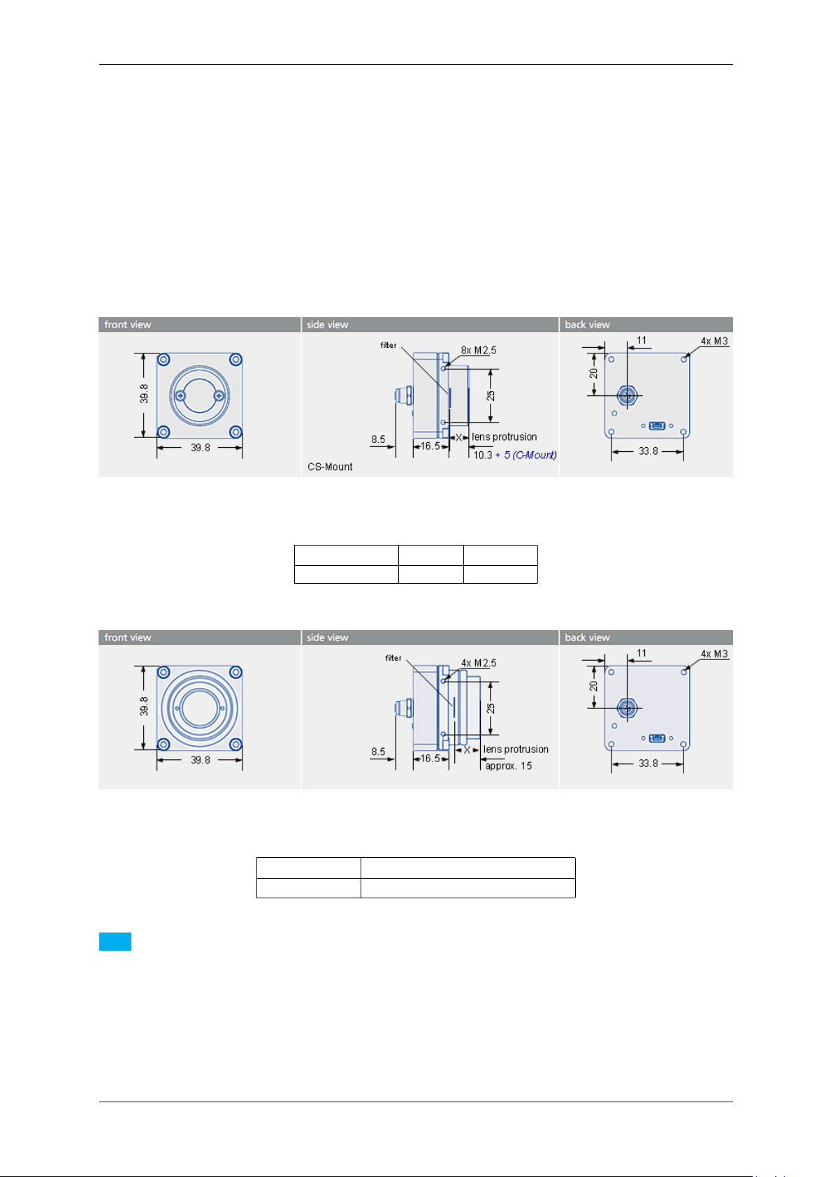
8.5 Single-board version with housing (mvBlueFOX-IGC2xx) 67
• C(S)-mount compatibility using mvBlueCOUGAR-X flange
• ambient temperature operation: 5..55 deg C / 30..80 RH
• ambient temperature storage: -25..60 deg C / 20..90 RH
8.5 Single-board version with housing (mvBlueFOX-IGC2xx)
8.5.1 Dimensions and connectors
Figure 28: mvBlueFOX-IGC
Lens protrusion C-Mount CS-Mount
X 10 mm 5 mm
Figure 29: mvBlueFOX-IGC-3xxx with adjustable backfocus
Lens protrusion C-Mount
X 8 mm (9.5 mm with max. Ø 20 mm)
Note
The mvBlueFOX-IGC has a serial I²C bus EEPROM with 16 KByte of which 8 KByte are reserved for the
firmware and 8 KByte can be used to store custom arbitrary data.
See also
UserDataEntry class description
MATRIX VISION GmbH
Page 75

68 CONTENTS
8.5.1.1 Mini-B USB (USB 2.0)
Figure 30: Mini-B USB
Pin Signal Comment
1 USBPOWER_IN Supply voltage
2 USB_DATA- Data
3 USB_DATA+ Data
4 ID Not connected
5 GND Ground
8.5.1.2 4-pin circular plug-in connector with lock (I/O)
Figure 31: 4-pin circular plug-in connector (female)
Pin Signal Comment Color (of cable)
1 IN0 + Opto-isolated digital input 0 (Positive voltage) brown
2 IN0 - Opto-isolated digital input 0 (Negative voltage) white
3 OUT0 + Opto-isolated digital output 0 (Positive voltage) blue
4 OUT0 - Opto-isolated digital output 0 (Negative voltage) black
Manufacturer: Binder
Part number: 79-3107-52-04
8.5.1.2.1 Electrical characteristic
Please have a look at the mvBlueFOX-MLC digital I/O characteristics (opto-isolated model) of the 12-pin Wire-toBoard Header (USB / Dig I/O) (p.59).
8.5.2 LED states
State LED
Camera is not connected or defect LED off
Camera is connected but not initialized or in "Power off" mode. Orange light on
Camera is connected and active Green light on
MATRIX VISION GmbH
Page 76

8.5 Single-board version with housing (mvBlueFOX-IGC2xx) 69
8.5.3 Positioning tolerances of sensor chip
The sensor's optical midpoint is in the center of the housing. However, several positioning tolerances in relation to
the housing are possible because of:
• Tolerance of mounting holes of the printed circuit board in relation to the edge of the lens holder housing is
not specified but produced according to general tolerance DIN ISO 2768 T1 fine.
• Tolerance of mounting holes on the printed circuit board because of the excess of the holes ± 0.1 mm (Figure
32; 2).
• Tolerance between conductive pattern and mounting holes on the printed circuit board.
Because there is no defined tolerance between conductive pattern and mounting holes, the general defined
tolerance of ± 0.1 mm is valid (Figure 32; 1 in the Y-direction ± 0.1 mm; 3 in the Z-direction ± 0.1 mm)
There are further sensor specific tolerances, e.g. for model mvBlueFOX-IGC200wG:
• Tolerance between sensor chip MT9V034 (die) and its package (connection pad)
– Chip position in relation to the mechanical center of the package: 0.2 mm (± 0.1mm) in the X- and
Y-direction (dimensions in the sensor data sheet according to ISO 1101)
• Tolerance between copper width of the sensor package and the pad width of the printed circuit board
During the soldering the sensor can swim to the edge of the pad: width of the pad 0.4 mm (possible tolerance
is not considered), width of pin at least 0.35 mm, max. offset: ± 0,025mm
Further specific tolerances of other models on request.
Figure 32: Positioning tolerances of sensor chip
Note
There are also tolerances in lens which could lead to optical offsets.
MATRIX VISION GmbH
Page 77

70 CONTENTS
9 Sensor overview
By default, the steps exposure and readout out of an image sensor are done one after the other. By design, CCD
sensors support overlap capabilities also combined with trigger (see figure). In contrast, so-called pipelined CMOS
sensors only support the overlapped mode. Even less CMOS sensors support the overlapped mode combined with
trigger. Please check the sensor summary (p. 70). In overlapping mode, the exposure starts the exposure time
earlier during readout.
Figure 1: Overlapping / pipelined exposure and readout
9.1 CCD sensors
The CCD sensors are highly programmable imager modules which incorporate the following features:
Sensors 0.3 Mpixels
resolution CCD
sensor (-220)
Sensor supplier Sony Sony Sony Sony Sony
Sensor name ICX098 AL/BL ICX424 AL/AQ ICX204 AL/AQ ICX267 AL/AQ ICX274 AL/AQ
Resolution 640 x 480
gray scale or
RGB Bayer mosaic
0.3 Mpixels
resolution CCD
sensor (-220a)
640 x 480
gray scale or
RGB Bayer mosaic
0.8 Mpixels
resolution CCD
sensor (-221)
1024 x 768
gray scale or
RGB Bayer mosaic
1.4 Mpixels
resolution CCD
sensor (-223)
1360 x 1024
gray scale or
RGB Bayer mosaic
1.9 Mpixels
resolution CCD
sensor (-224)
1600 x 1200
gray scale or
RGB Bayer mosaic
MATRIX VISION GmbH
Page 78

9.1 CCD sensors 71
Sensor format 1/4" 1/3" 1/3" 1/2" 1/1.8"
Pixel clock 12 MHz / 24
MHz
Max. frames
60 100 39
20 MHz / 40
MHz
20 MHz / 40
MHz
1
tbd / 40 MHz 20 MHz / 40
MHz
20 16
per second
Binning H+V H+V H+V H+V H+V
Exposure time 44 us - 10 s 26 us - 10 s 44 us - 10 s 33 us - 10 s 30 us - 10 s
ADC (on sensor board) resolution
Programmable
12 bit (up to
10 bit transmission)
12 bit (up to
10 bit transmission)
12 bit (up to
10 bit transmission)
X
12 bit (up to
10 bit transmission)
12 bit (up to
10 bit transmission)
analog gain and
offset
Frame integrat-
X
ing progressive
scan sensor (no
interlaced problems!)
High resolution X
High color re-
X
productivity (for
color version)
High sensitivity,
X
low dark current
Continuous
X
variable-speed
shutter
Pipelined in
X / continuous /
triggered mode
Low smear X
Excellent an-
X
tiblooming
characteristics
Programmable
X
exposure time
from usec to
sec.
Programmable
X
readout timing
with free capture windows
and partial scan
Trigger (Hard-
X / X
ware / Software)
Pipelined in
X / - X / - X / - X / - X / continuous /
triggered mode
Flash con-
X
trol output,
synchronous
to exposure
period
MATRIX VISION GmbH
Page 79

72 CONTENTS
More specific
data
1
With max. frame rate, image quality losings might be occur.
mvBlueFO←-
X-[Model]220
(0.3 Mpix [640
x 480]) (p. 190)
mvBlueFO←-
X-[Model]220a
(0.3 Mpix [640
x 480]) (p. 198)
mvBlueFO←-
X-[Model]221
(0.8 Mpix [1024
x 768]) (p. 206)
mvBlueFO←-
X-[Model]223
(1.4 Mpix
[1360 x 1024])
(p. 214)
mvBlueFO←-
X-[Model]224
(1.9 Mpix
[1600 x 1200])
(p. 222)
9.2 CMOS sensors
The CMOS sensor modules incorporate the following features:
Sensors: 0.4 Mpixels res-
olution CMOS
sensor (-200w)
Sensor supplier Aptina Aptina Aptina Aptina Aptina
Sensor name MT9V034 MT9M001 MT9M021 MT9M034 MT9P031
Resolution 752 x 480
gray scale or
RGB Bayer mosaic
Indication of
1/3" 1/2" 1/3" 1/3" 1/2.5"
sensor category to be
used
Pixel clock 40 MHz 40 MHz 40 MHz 40 MHz 40 MHz
Max. frames
93
2
per second (in
free-running full
frame mode)
Binning H+V (frame rate
170 Hz)
Exposure time 6 us - 4 s 100 us - 10 s 10 us - 4 s 10 us - 4 s 10 us - 10 s
ADC resolution 10 bit (10 / 8 bit
transmission)
SNR 42 dB 40 dB < 43 dB 37.4 dB
DR (normal /
55 dB / > 110dB61 dB / - > 61 dB / > 61 dB / >
HDR (p. 161))
Progressive
X X X X X
scan sensor
(no interlaced
problems!)
Rolling shutter - X - X X
Global shutter X - X - X
1.3 Mpixels resolution CMOS
sensor (-202a)
1280 x 1024
gray scale
1.2 Mpixels resolution CMOS
sensor (-x02b)
only -MLC/-IGC
1280 x 960
gray scale or
RGB Bayer mosaic
1.2 Mpixels resolution CMOS
1
sensor (-202d)
only -MLC/-IGC
1280 x 960
gray scale or
RGB Bayer mosaic
5.0 Mpixels resolution CMOS
1
sensor (-205)
2592 x 1944
gray scale or
RGB Bayer mosaic
25 25 25 5.8
H+V, Average←-
H+V (frame rate
unchanged)
H+V, Average←-
H+V (frame rate
unchanged)
H+V, Average←-
H+V (frame rate
unchanged)
H+V, 3H+3V,
AverageH+V,
Average3H+3V,
DroppingH+V,
Dropping3←-
H+3V (frame
rate 22.7 Hz)
10 bit (10 / 8 bit
transmission)
10 bit (10 / 8 bit
transmission)
10 bit (10 / 8 bit
transmission)
10 bit (10 / 8 bit
transmission)
65 dB /
110 dB (with
gray scale
version)
MATRIX VISION GmbH
Page 80

9.3 Output sequence of color sensors (RGB Bayer) 73
Trigger (Hardware / Software)
Pipelined in
continuous /
triggered mode
High color reproductivity (for
color version)
Programmable
readout timing
with free capture windows
and partial scan
Flash control output,
synchronous
to exposure
period
More specific
data
X / X X / - X / - X / - X / X
X / - X / - X / - X / - X / - (reset only)
X no no no no
X X X X X
X no no no no
mvBlueFO←-
X-[Model]200w
(0.4 Mpix [752
x 480]) (p. 231)
mvBlueFO←-
X-[Model]202a
(1.3 Mpix
[1280 x 1024])
(p. 234)
mvBlueFO←-
X-[Model]202b
(1.2 Mpix [1280
x 960]) (p. 237)
mvBlueFO←-
X-[Model]202d
(1.2 Mpix [1280
x 960]) (p. 241)
mvBlueFO←-
X-[Model]205
(5.0 Mpix
[2592 x 1944])
(p. 244)
1
The operation in device specific AEC/AGC mode is limited in (non continuous) triggered modes. AEC/AGC only
works while trigger signal is active. When the trigger signal is removed AEC/AGC stops and gain and exposure will
be set to a static value. This is due to a limitation of the sensor chip.
2
Frame rate increase with reduced AOI width, but only when width >= 560 pixels, below frame rate remains
unchanged.
Note
For further information about rolling shutter, please have a look at the practical report about rolling shutter on our website: https://www.matrix-vision.com/tl_files/mv11/Glossary/art_←-
rolling_shutter_en.pdf
For further information about image errors of image sensors, please have a look at
For further information about image errors of image sensors, please have a look at Correcting image errors
of a sensor (p. 143).
9.3 Output sequence of color sensors (RGB Bayer)
MATRIX VISION GmbH
Page 81

74 CONTENTS
Figure 2: Output sequence of RAW data
9.4 Bilinear interpolation of color sensors (RGB Bayer)
For Bayer demosaicing in the camera, we use bilinear interpolation:
Figure 3: Bilinear interpolation
1. Interpolation of green pixels: the average of the upper, lower, left and right pixel values is assigned as the G
value of the interpolated pixel.
For example:
G8 = --------------
(G3+G7+G9+G13)
4
For G7:
G7_new = 0.5*G7 + 0.5*---------------
(G1+G3+G11+G13)
4
2. Interpolation of red/blue pixels:
Interpolation of a red/blue pixel at a green position: the average of two adjacent pixel values in corresponding
color is assigned to the interpolated pixel.
For example:
B7 = ------- ; R7 = --------
(B6+B8) (R2+R12)
2 2
Interpolation of a red/blue pixel at a blue/red position: the average of four adjacent diagonal pixel values is
assigned to the interpolated pixel.
For example:
R8 = --------------- ; B12 = ---------------
(R2+R4+R12+R14) (B6+B8+B16+B18)
4 4
Any colored edge which might appear is due to Bayer false color artifacts.
Note
There are more advanced and adaptive methods (like edge sensitive ones) available if the host is doing this
debayering.
MATRIX VISION GmbH
Page 82

10.2 Cold mirror filter 75
10 Filters
MATRIX VISION offers two filters for the mvBlueFOX camera. The IR filter (p. 75) is part of the standard delivery
condition.
10.1 Hot mirror filter
The hot mirror filter FILTER IR-CUT 15,5X1,75 FE has great transmission in the visible spectrum and blocks out a
significant portion of the IR energy.
Technical data
Diameter 15.5 mm
Thickness 1.75 mm
Material Borofloat
Characteristics T = 50% @ 650 +/- 10 nm
T > 92% 390-620 nm
R
> 95% 700-1150 nm
avg
AOI = 0 degrees
Surface quality Polished on both sides
Surface irregularity 5/3x0.06 scratch/digs on both sides
Edges cut without bezel
Figure 1: FILTER IR-CUT 15,5X1,75 FE wavelengths and transmission diagram
10.2 Cold mirror filter
The FILTER DL-CUT 15,5X1,5 is a high-quality day light cut filter and has optically polished surfaces. The polished
surface allows the use of the filter directly in the path of rays in image processing applications. The filter is protected
against scratches during the transport by a protection film that has to be removed before the installing the filter.
Technical data
Diameter 15.5 mm
Thickness 1.5 +/- 0.2 mm
Material Solaris S 306
Characteristics T
MATRIX VISION GmbH
> 80% > 780 nm
avg
Page 83

76 CONTENTS
AOI = 0 degrees
Protective foil on both sides
Without antireflexion
Without bezel
Figure 2: FILTER DL-CUT 15,5X1,5 wavelengths and transmission diagram
Note
For further information how to change the filter, please have a look at our website:
http://www.matrix-vision.com/tl_files/mv11/Glossary/art_optical_filter←-
_en.pdf
10.3 Glass filter
It is also possible to choose the glass filter "FILTER GLASS 15,5X1,75" with following characteristics:
Technical data
Glass thickness 1.75 mm
Material Borofloat without coating
ground with protection chamfer
Surface quality polished on both sides P4
Surface irregularity 5/3x0.06 on both sides
MATRIX VISION GmbH
Page 84

11.1 wxPropView 77
11 Application Usage
11.1 wxPropView
wxPropView (p. 77) is an interactive GUI tool to acquire images and to configure the device and to display and
modify the device properties of MATRIX VISION GmbH hardware. After the installation you can find wxPropView
(p. 77)
• as an icon with the name "wxPropView" on the desktop (Windows) or
• in "∼/mvimpact-acquire/apps/mvPropView/x86" (Linux).
wxPropView - Introduction:
https://www.matrix-vision.com/tl_files/mv11/trainings/wxPropView/wx←-
PropView_Introduction/index.html
11.1.1 How to work with wxPropView
wxPropView - Working with wxPropView:
https://www.matrix-vision.com/tl_files/mv11/trainings/wxPropView/wx←-
PropView_WorkingWith/index.html
Depending on the driver version, wxPropView starts with the Quick Setup Wizard (p. 77) (as soon as a camera
with the right firmware version was selected used or a single camera with the right firmware was found) or without
it (p. 80).
11.1.1.1 Quick Setup Wizard
MATRIX VISION GmbH
Page 85

78 CONTENTS
Since
mvIMPACT Acquire 2.11.3
The Quick Setup Wizard is a tiny and powerful single window configuration tool to optimize the image quality
automatically and to set the most important parameters, which affect the image quality, in an easy way manually
and to get a preview of this changes. Settings will be accepted by clicking ok, otherwise the changes are cancelled.
Figure 1:Quick Setup Wizard started
Depending on the camera spectrum (gray or color sensor), it will automatically pre-set the camera so that image
quality is usually as best as possible.
"For all cameras:"
Image format is chosen as 10 bit (if possible) as a good compromise on image quality and speed.
It will further set
• "Exposure" to Auto,
• "Gain" to Auto,
• "Frame rate" to Auto based on current settings of the camera, and
• switches camera into continuous mode
"In case of gray:"
The above settings will be also applied whenever the "Gray Preset" button is pressed. For gray cameras it is herewith
assumed that image processing prefers a linear camera response.
"In case of color:"
It will additionally set
• "White balance" in the camera to Auto, and will apply
• a host based moderate "Gamma correction" (1.8), and lastly it will apply
• a host (PC) based sensor specific "Color Correction Matrix" and use the respective "sRGB display matrix".
These settings will also be applied whenever the "Color Preset" button is pressed. It is herewith assumed that color
camera image is optimized for best human visual feedback.
MATRIX VISION GmbH
Page 86

11.1 wxPropView 79
11.1.1.1.1 Changing the Presets
There are 3 presets:
• Gray
• Color
• Factory
Factory can be used as a fall back to quickly skip or remove all presets and load the factory default settings.
11.1.1.1.2 Modifying Settings
All auto modes can be switched off and all settings, such as Gain, Exposure etc. can be subsequently modified by
using:
• the sliders,
• the arrow keys, or
• entering real values with your keyboard.
Toggling Gamma button loads or unloads a host based 10 bit Gamma correction with a moderate value of 1.8 into
the signal processing path. Switch Gamma on if you require a gray level camera image to appear natural for the
human eye.
Toggling Color+ button switches both CCM and sRGB display matrix on and off. This optimizes the sensor color
response for the human eye and goes in conjunction with a display color response. Because sRGB displays are
mostly used and this is the default color space in Windows OS, these are preselected. If you require other display
matrices (e.g. Adobe or WideGamut) feel free to use the tree mode of wxPropView and select ColorTwistOutput←-
Correction accordingly.
Setting Black Level
Black level can be used if you require dark portions in the image to appear even darker or brighter. Please note that
this slider combines analog and digital settings meaningfully.
Setting Gain
Gain settings also combine analog and digital registers into one slider setting.
Setting Saturation
Saturation setting increases the color saturation to make the image appear more colored. It does not change
uncolored parts in the image nor changes the color tone or hue.
11.1.1.1.3 How to disable Quick Setup Wizard
Uncheck the checkbox "Show This Display When A Device Is Opened" to disable the Quick Setup Wizard to be
called automatically. Use the "Wizards" menu and select "Quick Setup" to open the Quick Setup Wizard once
again.
11.1.1.1.4 How to Return to the Tree Mode
Use OK to use the values and settings of the Quick Setup Wizard and go back to the tree mode of wxPropView.
Use Cancel to discard the Quick Setup Wizard values and settings and go back to wxPropView and use the former
(or default) settings.
MATRIX VISION GmbH
Page 87

80 CONTENTS
11.1.1.1.5 Image Display Functions
Quick Setup Wizard allows zooming into the image by right clicking in the image area and unchecking "Fit To
Screen" mode. Use the mouse wheel to zoom in or out. Check "Fit To Screen" mode, if you want the complete
camera image to be sized in the window screen size.
11.1.1.1.6 Known Restrictions
In cases of Tungsten (artificial) light, camera brightness may tend to oscillations if Auto functions are used. This
can be minimized or avoided by setting the frame frequency to an integer divisor of the mains frequency.
• Example:
– Europe: 50 Hz; Set frame rate to 100, 50, 25 12.5 fps or appropriate.
– In countries with 60 Hz use 120, 60, 30 or 15. . . accordingly.
11.1.1.2 First View of wxPropView
wxPropView (p.77) consists of several areas:
Figure 2:wxPropView started
MATRIX VISION GmbH
Page 88

11.1 wxPropView 81
• "Menu Bar"
(to work with wxPropView (p.77) using the menu)
• "Upper Tool Bar"
(to select and initialize a device, acquire images, play a recorder sequence)
• "Left Tool Bar"
(to hide and show parts of the GUI)
• "Status Tool Bar"
• "Main Window" with
– "Grid"
(tree control with the device settings accessible by the user)
– "Display"
(for the acquired images)
– "Analysis"
(information about whole images or an AOI)
By clicking on F1 you will get the HELP dialog.
Now, you can initialize a device by
• selecting it in the drop down list in the "Upper Tool Bar" and
• clicking on "Use".
After having successfully initialized a device the tree control in the lower left part of the "Main Window" will display
the properties (settings or parameters) (according to the "interface layout") accessible by the user.
You've also got the possibility to set your "User Experience". According to the chosen experience, the level of
visibility is different:
• Beginner (basic camera settings/properties are visible)
• Expert (e.g. all advanced image processing are visible)
• Guru (all settings/properties are visible)
Properties displayed in light grey cannot be modified by the user. Only the properties, which actually have an impact
on the resulting image, will be visible. Therefore, certain properties might appear or disappear when modifying
another properties.
To permanently commit a modification made with the keyboard the ENTER must be pressed. If leaving the editor
before pressing ENTER will restore the old value.
MATRIX VISION GmbH
Page 89

82 CONTENTS
11.1.1.3 How to see the first image
As described earlier, for each recognized device in the system the devices serial number will appear in the drop
down menu in the upper left corner of the "Upper Tool Bar". When this is the first time you start the application after
the system has been booted this might take some seconds when working with devices that are not connected to
the host system via PCI or PCIe.
Once you have selected the device of your choice from the drop down menu click on the "Use" button to open it.
When the device has been opened successfully, the remaining buttons of the dialog will be enabled:
Note
Following screenshots are representative and where made using a mvBlueFOX camera as the capturing
device.
For color sensors, it is recommended to perform a white balance (p. 102) calibration before acquiring images. This
will improve the quality of the resulting images significantly.
Figure 3:wxPropView - First start
MATRIX VISION GmbH
Page 90

11.1 wxPropView 83
Now, you can capture an image ("Acquisition Mode": "SingleFrame") or display live images ("Continuous"). Just
• select an "Acquisition Mode" e.g. "SingleFrame" and
• click the "Acquire" button.
Note
The techniques behind the image acquisition can be found in the developers sections.
The frame rate depends on
• the camera,
• the pixel clock of the sensor
11.1.1.3.1 Record Mode
It is also possible to record image sequences using wxPropView.
1. For this, you have to set the size of the recorder in "System Settings -> RequestCount" e.g. to 100.
This will save the last 100 requests in the request queue of the driver, i.e. the image data inluding the request
info like frame number, time stamp, etc.
2. Afterwards you can start the recording by clicking the Rec. button.
3. With the Next and Prev. buttons you can display the single images.
If you switched on the request info overlay (righ-click on the display area and select the entry to activate this
feature), these information will be displayed on the image, too. With the timestamp you can see the interval of the
single frames in microseconds.
MATRIX VISION GmbH
Page 91

84 CONTENTS
Figure 4: wxPropView - Using the record mode.
11.1.1.4 Storing and restoring settings
When wxPropView (p. 77) is started for the first time, the values of properties set to their default values will be
displayed in green to indicate that these values have not been modified by the user so far. Modified properties (even
if the value is the same as the default) will be displayed in black.
Figure 5: wxPropView - Storing settings
MATRIX VISION GmbH
Page 92

11.1 wxPropView 85
Settings can be stored in several ways (via the "Menu Bar": "Action -> Capture Settings -> Save Active Device
Settings"):
• "As Default Settings For All Devices Belonging To The Same Family (Per User Only)": As the start-up param-
eters for every device belonging to the same family, e.g. for mvBlueCOUGAR-X, mvBlueCOUGAR-XD.
• "As Default Settings For All Devices Belonging To The Same Family And Product Type": As the start-up
parameters for every device belonging to the same product, e.g. for any mvBlueCOUGAR-X but not for
mvBlueCOUGAR-XD.
• "As Default Settings For This Device(Serial Number)": As the start-up parameters for the currently selected
device.
• "To A File": As an XML file that can be used e.g. to transport a setting from one machine to another or even
to use the settings configured for one platform on another (Windows <-> Linux).
During the startup of a device, all these setting possibilities show different behaviors. The differences are described
in chapter Settings behaviour during startup (p. 42)
Restoring of settings previously stored works in a similar way. After a device has been opened the settings will be
loaded automatically as described in Settings behaviour during startup (p. 42)
However, at runtime the user has different load settings possibilities (via the "Menu Bar": "Action -> Capture Settings
-> Load Active Device Settings")
• explicitly load the device family specific settings stored on this machine (from "The Default Settings Location
For This Devices Family (Per User Only)")
• explicitly load the product specific settings stored on this machine (from "The Default Settings Location For
This Devices Family And Product Type)")
• explicitly load the device specific settings stored on this machine (from "The Default Settings Location For
This Device(Serial Number)")
• explicitly load device family specific settings from a XML file previously created ("From A File")
Note
With "Action -> Capture Settings -> Manage..." you can delete the settings which were saved on the system.
MATRIX VISION GmbH
Figure 6: wxPropView - Restoring settings
Page 93

86 CONTENTS
11.1.1.5 Properties
All properties and functions can be displayed in the list control on the lower left side of the dialog. To modify the
value of a property select the edit control right of the properties name. Property values, which refer to the default
value of the device, are displayed in green. A property value once modified by the user will be displayed in black
(even if the value itself has not changed). To restore its default value of a single property
• right click on the name of the property and
• select "Restore Default".
To restore the default value for a complete list (which might include sub-lists)
• right click on the name of a list and
• select "Restore Default".
In this case a popup window will be opened and you have to confirm again.
Figure 7: wxPropView - Restore the default value of a property
MATRIX VISION GmbH
Page 94

11.1 wxPropView 87
Most properties store one value only, thus they will appear as a single entry in the property grid. However, properties
are capable of storing more than one value, if this is desired. A property storing more than one value will appear as
a parent list item with a WHITE background color (lists will be displayed with a grey background) and as many child
elements as values stored by the property. The PARENT grid control will display the number of values stored by
the property, every child element will display its corresponding value index.
If supported by the property, the user might increase or decrease the number of values stored by right clicking on
the PARENT grid element. If the property allows the modification the pop up menu will contain additional entries
now:
Figure 8: wxPropView - A resizable property
When a new value has been created it will be displayed as a new child item of the parent grid item:
Figure 9: wxPropView - A resized property
Currently, only the last value can be removed via the GUI and a value can't be removed, when a property stores
one value only.
Also the user might want to set all (or a certain range of) values for properties that store multiple values with a single
operation. If supported by the property, this can also be achieved by right clicking on the PARENT grid element. If
the property allows this modification the pop up menu will again contain additional entries:
MATRIX VISION GmbH
Page 95

88 CONTENTS
Figure 10: wxPropView - Setting multiple property values
It's possible to either set all (or a range of) elements of the property to a certain value OR to define a value range,
that then will be applied to the range of property elements selected by the user. The following example will explain
how this works:
Figure 11: wxPropView - Setting multiple property values within a certain value range
MATRIX VISION GmbH
Page 96

11.1 wxPropView 89
In this sample the entries 0 to 255 of the property will be assigned the value range of 0 to 255. This will result in the
following values AFTER applying the values:
Figure 12: wxPropView - After applying the value range to a property
11.1.1.6 Methods
Method appears as entries in the tree control as well. However, their name and behavior differs significantly from
the behavior of properties. The names of method objects will appear in 'C' syntax like e.g. "int function( char∗, int
)". This will specific a function returning an integer value and expecting a string and an integer as input parameters.
To execute a method object
• right click on the name of a method and
• select "Execute" from the popup menu:
Figure 13: wxPropView - Calling a method object
Parameters can be passed to methods by selecting the edit control left of a method object. Separate the parameters
by blanks. So to call a function expecting a string and an integer value you e.g. might enter "testString 0"
into the edit control left of the method.
The return value (in almost every case an error code as an integer) will be displayed in the lower right corner of the
tree control. The values displayed here directly correspond the error codes defined in the interface reference and
therefore will be of type TDMR_ERROR or TPROPHANDLING_ERROR.
MATRIX VISION GmbH
Page 97

90 CONTENTS
11.1.1.7 Copy grid data to the clipboard
Since wxPropView (p. 77) version 1.11.0 it is possible to copy analysis data to the clipboard. The data will be copied
in CSV style thus can be pasted directly into tools like Open Office™ or Microsoft® Office™.
Just
• right-click on the specific analysis grid when in numerical display mode and
• select "Copy grid to clipboard" from the pop up menu.
Figure 14: wxPropView - Copying grid data to the clipboard
11.1.1.8 Import and Export images
wxPropView (p. 77) offers a wide range of image formats that can be used for exporting captured image to a file.
Some formats e.g. like packed YUV 4:2:2 with 10 bit per component are rather special thus they can't be stored
into a file like e.g. offered by the BMP file header. When a file is stored in a format, that does not support this data
type wxPropView (p.77) will convert this image into something that matches the original image format as close as
possible. This, however, can result in the loss of data. In order to allow the storage of the complete information
contained in a captured image wxPropView (p. 77) allows to store the data in a raw format as well. This file format
will just contain a binary dump of the image with no leader or header information. However, the file name will
automatically be extended by information about the image to allow the restoring of the data at a later time.
All image formats, that can be exported can also be imported again. Importing a file can be done in 3 different
ways:
• via the menu (via the "Menu Bar": "Action -> Load image...")
• by dragging an image file into an image display within wxPropView (p. 77)
• by starting wxPropView (p. 77) from the command line passing the file to open as a command line param-
eter (p. 115) (under Windows® e.g. "wxPropView.exe MyImage.png" followed by [ENTER])
MATRIX VISION GmbH
Page 98

11.1 wxPropView 91
When importing a "∗.raw" image file a small dialog will pop up allowing the user to define the dimensions and
the pixel format of the image. When the file name has been generated using the image storage function offered
by wxPropView (p. 77), the file name will be passed and the extracted information will automatically be set in the
dialog thus the user simply needs to confirm this information is correct.
Figure 15: wxPropView - Raw image file import
11.1.1.9 Setting up multiple display support and/or work with several capture settings in parallel
wxPropView (p.77) is capable of
• dealing with multiple capture settings or acquisition sequences for a single device and in addition to that
• it can be configured to deal with multiple image displays.
The amount of parallel image displays can be configured via the command line parameter (p. 115) "dcx" and
"dcy". In this step by step setup wxPropView (p. 77) has been started like this from the command line:
wxPropView dcx=1 dcy=2
This will result in 1 display in horizontal direction and 2 in vertical direction.
Since
mvIMPACT Acquire 2.18.1
Is is also possible to change the amount of display at runtime via "Settings -> Image Displays -> Configure Image
Display Count":
MATRIX VISION GmbH
Page 99

92 CONTENTS
Figure 16: wxPropView - Create capture setting
Additional capture settings can be created via "Menu Bar": "Capture -> Capture Settings -> Create Capture
Settings". The property grid will display these capture settings either in "Developers" or in "Multiple Settings
View".
Now, in order to set up wxPropView (p. 77) to work with 2 instead of one capture setting,
1. Various additional capture setting can be created. In order to understand what a capture setting actually is
please refer to
• "Working with settings" chapter of the "mvIMPACT Acquire API" manuals.
Creating a capture setting is done via "Capture -> Capture Settings -> Create Capture Setting".
Figure 17: wxPropView - Create capture setting
MATRIX VISION GmbH
Page 100

11.1 wxPropView 93
2. Then, the user is asked for the name of the new setting.
Figure 18: wxPropView - Create capture setting - Choosing name
3. And finally for the base this new setting shall be derived from.
Figure 19: wxPropView - Create capture setting - Choosing base
Afterwards, in this example we end up having 2 capture settings:
• a "Base" setting, which is always available
• a "NewSetting1", which has been derived from "Base".
MATRIX VISION GmbH
 Loading...