

Page 1
mvBlueCOUGAR-X/-XD
Technical Manual
English - Version 4.36
Page 2

CONTENTS i
Contents
1 About this manual 2
1.1 Composition of the manual . . . . . . . . . . . . . . . . . . . . . . . . . . . . . . . . . . . . . . 2
1.2 How to get started? . . . . . . . . . . . . . . . . . . . . . . . . . . . . . . . . . . . . . . . . . . 3
1.2.1 Introduction . . . . . . . . . . . . . . . . . . . . . . . . . . . . . . . . . . . . . . . . . . 3
1.2.2 Basics . . . . . . . . . . . . . . . . . . . . . . . . . . . . . . . . . . . . . . . . . . . . . 3
1.2.3 Installation . . . . . . . . . . . . . . . . . . . . . . . . . . . . . . . . . . . . . . . . . . 7
1.2.4 Programming . . . . . . . . . . . . . . . . . . . . . . . . . . . . . . . . . . . . . . . . . 7
2 Imprint 8
3 Legal notice 9
3.1 Introduction . . . . . . . . . . . . . . . . . . . . . . . . . . . . . . . . . . . . . . . . . . . . . . 9
3.2 cJSON . . . . . . . . . . . . . . . . . . . . . . . . . . . . . . . . . . . . . . . . . . . . . . . . . 9
3.2.1 cJSON license . . . . . . . . . . . . . . . . . . . . . . . . . . . . . . . . . . . . . . . . 9
3.3 Unity . . . . . . . . . . . . . . . . . . . . . . . . . . . . . . . . . . . . . . . . . . . . . . . . . . 9
3.3.1 Unity license . . . . . . . . . . . . . . . . . . . . . . . . . . . . . . . . . . . . . . . . . 9
4 Revisions 11
5 Graphic Symbols 24
5.1 Notes, Warnings, Attentions . . . . . . . . . . . . . . . . . . . . . . . . . . . . . . . . . . . . . . 24
5.2 Webcasts . . . . . . . . . . . . . . . . . . . . . . . . . . . . . . . . . . . . . . . . . . . . . . . 24
6 Important information 25
6.1 Important safety instructions . . . . . . . . . . . . . . . . . . . . . . . . . . . . . . . . . . . . . 25
6.2 Operating considerations . . . . . . . . . . . . . . . . . . . . . . . . . . . . . . . . . . . . . . . 25
6.2.1 Important safety notes . . . . . . . . . . . . . . . . . . . . . . . . . . . . . . . . . . . . 25
6.2.2 Handling and cleaning . . . . . . . . . . . . . . . . . . . . . . . . . . . . . . . . . . . . 26
6.2.3 Installing . . . . . . . . . . . . . . . . . . . . . . . . . . . . . . . . . . . . . . . . . . . 26
6.2.4 Optimizing performance and life time . . . . . . . . . . . . . . . . . . . . . . . . . . . . . 26
6.2.5 Connectors . . . . . . . . . . . . . . . . . . . . . . . . . . . . . . . . . . . . . . . . . . 26
6.2.6 Cleaning . . . . . . . . . . . . . . . . . . . . . . . . . . . . . . . . . . . . . . . . . . . 26
6.2.7 Adjusting the C-mount . . . . . . . . . . . . . . . . . . . . . . . . . . . . . . . . . . . . 27
6.2.8 Additional temperature and power consumption notes concerning mvBlueCOUGAR-XD and
mvBlueCOUGAR-X2xx . . . . . . . . . . . . . . . . . . . . . . . . . . . . . . . . . . . . 28
6.3 European Union Declaration of Conformity statement . . . . . . . . . . . . . . . . . . . . . . . . 28
6.4 Legal notice . . . . . . . . . . . . . . . . . . . . . . . . . . . . . . . . . . . . . . . . . . . . . . 33
6.4.1 For customers in the U.S.A. . . . . . . . . . . . . . . . . . . . . . . . . . . . . . . . . . . 33
6.4.2 For customers in Canada . . . . . . . . . . . . . . . . . . . . . . . . . . . . . . . . . . . 34
6.4.3 Pour utilisateurs au Canada . . . . . . . . . . . . . . . . . . . . . . . . . . . . . . . . . 34
MATRIX VISION GmbH
Page 3

ii CONTENTS
7 Introduction 35
7.1 Order code nomenclature . . . . . . . . . . . . . . . . . . . . . . . . . . . . . . . . . . . . . . . 35
7.1.1 mvBlueCOUGAR-X . . . . . . . . . . . . . . . . . . . . . . . . . . . . . . . . . . . . . . 35
7.1.2 mvBlueCOUGAR-XD . . . . . . . . . . . . . . . . . . . . . . . . . . . . . . . . . . . . . 36
7.1.3 mvBlueCOUGAR-3X . . . . . . . . . . . . . . . . . . . . . . . . . . . . . . . . . . . . . 37
7.1.4 Ordering code samples . . . . . . . . . . . . . . . . . . . . . . . . . . . . . . . . . . . . 37
7.2 What's inside and accessories . . . . . . . . . . . . . . . . . . . . . . . . . . . . . . . . . . . . 37
8 Quickstart 39
8.1 Windows . . . . . . . . . . . . . . . . . . . . . . . . . . . . . . . . . . . . . . . . . . . . . . . . 39
8.1.1 System requirements . . . . . . . . . . . . . . . . . . . . . . . . . . . . . . . . . . . . . 39
8.1.2 Installing the mvGenTL-Acquire driver . . . . . . . . . . . . . . . . . . . . . . . . . . . . 40
8.1.3 Optimizing the network configuration . . . . . . . . . . . . . . . . . . . . . . . . . . . . . 43
8.1.4 Adjusting the network controller . . . . . . . . . . . . . . . . . . . . . . . . . . . . . . . 44
8.1.5 Additional network configuration for mvBlueCOUGAR-XD . . . . . . . . . . . . . . . . . . 47
8.2 Linux . . . . . . . . . . . . . . . . . . . . . . . . . . . . . . . . . . . . . . . . . . . . . . . . . . 49
8.2.1 System requirements . . . . . . . . . . . . . . . . . . . . . . . . . . . . . . . . . . . . . 49
8.2.2 Installing the mvGenTL-Acquire driver . . . . . . . . . . . . . . . . . . . . . . . . . . . . 50
8.2.3 Optimizing the network configuration . . . . . . . . . . . . . . . . . . . . . . . . . . . . . 52
8.2.4 Adjusting the network controller . . . . . . . . . . . . . . . . . . . . . . . . . . . . . . . 53
8.2.5 Additional network configuration for mvBlueCOUGAR-XD . . . . . . . . . . . . . . . . . . 53
8.3 Connecting the camera . . . . . . . . . . . . . . . . . . . . . . . . . . . . . . . . . . . . . . . . 55
8.3.1 Communicating with the camera . . . . . . . . . . . . . . . . . . . . . . . . . . . . . . . 56
8.3.2 Setting up the camera . . . . . . . . . . . . . . . . . . . . . . . . . . . . . . . . . . . . 57
8.3.3 Settings behaviour during startup . . . . . . . . . . . . . . . . . . . . . . . . . . . . . . . 58
8.4 Relationship between driver, firmware, FPGA file and user settings . . . . . . . . . . . . . . . . . 59
MATRIX VISION GmbH
Page 4

CONTENTS iii
9 Technical data 64
9.1 mvBlueCOUGAR-X . . . . . . . . . . . . . . . . . . . . . . . . . . . . . . . . . . . . . . . . . . 64
9.1.1 Dimensions . . . . . . . . . . . . . . . . . . . . . . . . . . . . . . . . . . . . . . . . . . 64
9.1.2 Connectors . . . . . . . . . . . . . . . . . . . . . . . . . . . . . . . . . . . . . . . . . . 67
9.1.3 Signal LED . . . . . . . . . . . . . . . . . . . . . . . . . . . . . . . . . . . . . . . . . . 74
9.2 mvBlueCOUGAR-X-POE-I . . . . . . . . . . . . . . . . . . . . . . . . . . . . . . . . . . . . . . 75
9.2.1 Dimensions . . . . . . . . . . . . . . . . . . . . . . . . . . . . . . . . . . . . . . . . . . 75
9.2.2 Connectors . . . . . . . . . . . . . . . . . . . . . . . . . . . . . . . . . . . . . . . . . . 76
9.3 mvBlueCOUGAR-XD . . . . . . . . . . . . . . . . . . . . . . . . . . . . . . . . . . . . . . . . . 79
9.3.1 Dimensions . . . . . . . . . . . . . . . . . . . . . . . . . . . . . . . . . . . . . . . . . . 79
9.3.2 Connectors . . . . . . . . . . . . . . . . . . . . . . . . . . . . . . . . . . . . . . . . . . 80
9.3.3 Signal LED . . . . . . . . . . . . . . . . . . . . . . . . . . . . . . . . . . . . . . . . . . 86
9.4 mvBlueCOUGAR-3X . . . . . . . . . . . . . . . . . . . . . . . . . . . . . . . . . . . . . . . . . 87
9.4.1 Dimensions . . . . . . . . . . . . . . . . . . . . . . . . . . . . . . . . . . . . . . . . . . 87
9.4.2 Model specific features . . . . . . . . . . . . . . . . . . . . . . . . . . . . . . . . . . . . 89
9.5 Summary of components . . . . . . . . . . . . . . . . . . . . . . . . . . . . . . . . . . . . . . . 89
9.6 Summary of advanced features . . . . . . . . . . . . . . . . . . . . . . . . . . . . . . . . . . . . 90
10 Sensor overview 93
10.1 Image data flow . . . . . . . . . . . . . . . . . . . . . . . . . . . . . . . . . . . . . . . . . . . . 93
10.2 CCD sensors . . . . . . . . . . . . . . . . . . . . . . . . . . . . . . . . . . . . . . . . . . . . . 93
10.2.1 mvBlueCOUGAR-XD specific CCD sensors . . . . . . . . . . . . . . . . . . . . . . . . . 95
10.2.2 Negative gain . . . . . . . . . . . . . . . . . . . . . . . . . . . . . . . . . . . . . . . . . 97
10.3 mvBlueCOUGAR-X specific CMOS sensors . . . . . . . . . . . . . . . . . . . . . . . . . . . . . 98
10.3.1 Sony Pregius . . . . . . . . . . . . . . . . . . . . . . . . . . . . . . . . . . . . . . . . . 98
10.3.2 Aptina, CMOSIS, e2v . . . . . . . . . . . . . . . . . . . . . . . . . . . . . . . . . . . . . 99
10.3.3 mvBlueCOUGAR-XD specific CMOS sensors . . . . . . . . . . . . . . . . . . . . . . . . 102
10.4 Output sequence of color sensors (RGB Bayer) . . . . . . . . . . . . . . . . . . . . . . . . . . . 104
10.5 Bilinear interpolation of color sensors (RGB Bayer) . . . . . . . . . . . . . . . . . . . . . . . . . . 105
10.6 Supported image formats . . . . . . . . . . . . . . . . . . . . . . . . . . . . . . . . . . . . . . . 105
MATRIX VISION GmbH
Page 5

iv CONTENTS
11 Filters 107
11.1 Hot mirror filter . . . . . . . . . . . . . . . . . . . . . . . . . . . . . . . . . . . . . . . . . . . . . 107
11.2 Cold mirror filter . . . . . . . . . . . . . . . . . . . . . . . . . . . . . . . . . . . . . . . . . . . . 107
11.3 Glass filter . . . . . . . . . . . . . . . . . . . . . . . . . . . . . . . . . . . . . . . . . . . . . . . 108
12 Application Usage 109
12.1 wxPropView . . . . . . . . . . . . . . . . . . . . . . . . . . . . . . . . . . . . . . . . . . . . . . 109
12.1.1 How to work with wxPropView . . . . . . . . . . . . . . . . . . . . . . . . . . . . . . . . 110
12.1.2 How to configure a device . . . . . . . . . . . . . . . . . . . . . . . . . . . . . . . . . . 135
12.1.3 Command-line options . . . . . . . . . . . . . . . . . . . . . . . . . . . . . . . . . . . . 141
12.2 mvGigEConfigure . . . . . . . . . . . . . . . . . . . . . . . . . . . . . . . . . . . . . . . . . . . 142
12.2.1 Install GigE Vision capture filter . . . . . . . . . . . . . . . . . . . . . . . . . . . . . . . . 142
12.2.2 Remove GigE Vision capture filter . . . . . . . . . . . . . . . . . . . . . . . . . . . . . . 143
12.2.3 Command-line options . . . . . . . . . . . . . . . . . . . . . . . . . . . . . . . . . . . . 143
12.3 mvIPConfigure . . . . . . . . . . . . . . . . . . . . . . . . . . . . . . . . . . . . . . . . . . . . . 145
12.3.1 Configure a GigE Vision device . . . . . . . . . . . . . . . . . . . . . . . . . . . . . . . . 146
12.3.2 Recover a misconfigured GigE Vision device . . . . . . . . . . . . . . . . . . . . . . . . . 148
12.4 mvDeviceConfigure . . . . . . . . . . . . . . . . . . . . . . . . . . . . . . . . . . . . . . . . . . 149
12.4.1 How to set the device ID . . . . . . . . . . . . . . . . . . . . . . . . . . . . . . . . . . . 150
12.4.2 How to update the firmware . . . . . . . . . . . . . . . . . . . . . . . . . . . . . . . . . . 152
12.4.3 Preserving UserSet settings when updating the Firmware . . . . . . . . . . . . . . . . . . 155
12.4.4 How to disable CPU sleep states a.k.a. C states (< Windows 8) . . . . . . . . . . . . . . 156
12.4.5 Command-line options . . . . . . . . . . . . . . . . . . . . . . . . . . . . . . . . . . . . 158
MATRIX VISION GmbH
Page 6

CONTENTS v
13 GenICam and Advanced Features 160
13.1 Introduction . . . . . . . . . . . . . . . . . . . . . . . . . . . . . . . . . . . . . . . . . . . . . . 160
13.2 Device Control . . . . . . . . . . . . . . . . . . . . . . . . . . . . . . . . . . . . . . . . . . . . . 161
13.3 Image Format Control . . . . . . . . . . . . . . . . . . . . . . . . . . . . . . . . . . . . . . . . . 162
13.4 Acquisition Control . . . . . . . . . . . . . . . . . . . . . . . . . . . . . . . . . . . . . . . . . . 163
13.5 Counter And Timer Control . . . . . . . . . . . . . . . . . . . . . . . . . . . . . . . . . . . . . . 166
13.6 Analog Control . . . . . . . . . . . . . . . . . . . . . . . . . . . . . . . . . . . . . . . . . . . . . 167
13.7 mv Logic Gate Control . . . . . . . . . . . . . . . . . . . . . . . . . . . . . . . . . . . . . . . . . 168
13.8 Color Transformation Control . . . . . . . . . . . . . . . . . . . . . . . . . . . . . . . . . . . . . 169
13.9 mv Flat Field Correction Control . . . . . . . . . . . . . . . . . . . . . . . . . . . . . . . . . . . . 170
13.10Event Control . . . . . . . . . . . . . . . . . . . . . . . . . . . . . . . . . . . . . . . . . . . . . 170
13.11Chunk Data Control . . . . . . . . . . . . . . . . . . . . . . . . . . . . . . . . . . . . . . . . . . 171
13.12File Access Control . . . . . . . . . . . . . . . . . . . . . . . . . . . . . . . . . . . . . . . . . . 172
13.13mv Serial Interface Control . . . . . . . . . . . . . . . . . . . . . . . . . . . . . . . . . . . . . . 173
13.14Digital I/O Control . . . . . . . . . . . . . . . . . . . . . . . . . . . . . . . . . . . . . . . . . . . 173
13.15LUT Control . . . . . . . . . . . . . . . . . . . . . . . . . . . . . . . . . . . . . . . . . . . . . . 174
13.15.1 mvLUTType . . . . . . . . . . . . . . . . . . . . . . . . . . . . . . . . . . . . . . . . . . 175
13.15.2 mvLUTInputData . . . . . . . . . . . . . . . . . . . . . . . . . . . . . . . . . . . . . . . 175
13.15.3 mvLUTMapping . . . . . . . . . . . . . . . . . . . . . . . . . . . . . . . . . . . . . . . . 175
13.15.4 LUT support in MATRIX VISION cameras . . . . . . . . . . . . . . . . . . . . . . . . . . 175
13.16Sequencer Control . . . . . . . . . . . . . . . . . . . . . . . . . . . . . . . . . . . . . . . . . . 179
13.16.1 Sequencer overview . . . . . . . . . . . . . . . . . . . . . . . . . . . . . . . . . . . . . 179
13.16.2 Configuration of a sequencer set . . . . . . . . . . . . . . . . . . . . . . . . . . . . . . . 180
13.17mv Defective Pixel Correction Control . . . . . . . . . . . . . . . . . . . . . . . . . . . . . . . . . 184
13.18Transport Layer Control . . . . . . . . . . . . . . . . . . . . . . . . . . . . . . . . . . . . . . . . 184
13.19User Set Control . . . . . . . . . . . . . . . . . . . . . . . . . . . . . . . . . . . . . . . . . . . . 185
13.20mv Frame Average Control (only with specific models) . . . . . . . . . . . . . . . . . . . . . . . . 186
13.21mv High Dynanmic Range Control (only with specific sensor models) . . . . . . . . . . . . . . . . 187
14 C developers 188
MATRIX VISION GmbH
Page 7

vi CONTENTS
15 C++ developers 189
16 .NET developers 190
17 Python developers 191
17.1 Introduction . . . . . . . . . . . . . . . . . . . . . . . . . . . . . . . . . . . . . . . . . . . . . . 191
17.2 Building . . . . . . . . . . . . . . . . . . . . . . . . . . . . . . . . . . . . . . . . . . . . . . . . 191
17.2.1 Windows . . . . . . . . . . . . . . . . . . . . . . . . . . . . . . . . . . . . . . . . . . . 191
17.2.2 Linux . . . . . . . . . . . . . . . . . . . . . . . . . . . . . . . . . . . . . . . . . . . . . 192
17.3 Using . . . . . . . . . . . . . . . . . . . . . . . . . . . . . . . . . . . . . . . . . . . . . . . . . 192
18 DirectShow Interface 195
18.1 Supported Interfaces . . . . . . . . . . . . . . . . . . . . . . . . . . . . . . . . . . . . . . . . . 195
18.1.1 IAMCameraControl . . . . . . . . . . . . . . . . . . . . . . . . . . . . . . . . . . . . . . 195
18.1.2 IAMDroppedFrames . . . . . . . . . . . . . . . . . . . . . . . . . . . . . . . . . . . . . 195
18.1.3 IAMStreamConfig . . . . . . . . . . . . . . . . . . . . . . . . . . . . . . . . . . . . . . . 195
18.1.4 IAMVideoProcAmp . . . . . . . . . . . . . . . . . . . . . . . . . . . . . . . . . . . . . . 195
18.1.5 IKsPropertySet . . . . . . . . . . . . . . . . . . . . . . . . . . . . . . . . . . . . . . . . 195
18.1.6 ISpecifyPropertyPages . . . . . . . . . . . . . . . . . . . . . . . . . . . . . . . . . . . . 195
18.2 Logging . . . . . . . . . . . . . . . . . . . . . . . . . . . . . . . . . . . . . . . . . . . . . . . . 195
18.3 Registering and renaming devices for DirectShow usage . . . . . . . . . . . . . . . . . . . . . . . 196
18.3.1 Registering devices . . . . . . . . . . . . . . . . . . . . . . . . . . . . . . . . . . . . . . 196
18.3.2 Renaming devices . . . . . . . . . . . . . . . . . . . . . . . . . . . . . . . . . . . . . . 198
18.3.3 Make silent registration . . . . . . . . . . . . . . . . . . . . . . . . . . . . . . . . . . . . 199
MATRIX VISION GmbH
Page 8

CONTENTS vii
19 Troubleshooting 200
19.1 I can see the camera in mvIPConfigure, but I cannot access the camera . . . . . . . . . . . . . . 200
19.2 Image Data is lost (incomplete frames) . . . . . . . . . . . . . . . . . . . . . . . . . . . . . . . . 200
19.3 There are image error counts . . . . . . . . . . . . . . . . . . . . . . . . . . . . . . . . . . . . . 200
19.4 I get an exception when setting offsetX or offsetY . . . . . . . . . . . . . . . . . . . . . . . . . . 201
19.5 Cognex VisionPro . . . . . . . . . . . . . . . . . . . . . . . . . . . . . . . . . . . . . . . . . . . 201
19.5.1 I cannot use mvBlueCOUGAR-XD . . . . . . . . . . . . . . . . . . . . . . . . . . . . . . 201
19.5.2 I cannot initialize 4 Tap sensor mvBlueCOUGAR-XDs . . . . . . . . . . . . . . . . . . . . 202
19.6 I get an oscillating frame rate . . . . . . . . . . . . . . . . . . . . . . . . . . . . . . . . . . . . . 206
19.7 I cannot focus on distant objects . . . . . . . . . . . . . . . . . . . . . . . . . . . . . . . . . . . 206
19.8 Accessing log files . . . . . . . . . . . . . . . . . . . . . . . . . . . . . . . . . . . . . . . . . . . 206
19.8.1 Windows . . . . . . . . . . . . . . . . . . . . . . . . . . . . . . . . . . . . . . . . . . . 206
19.8.2 Linux . . . . . . . . . . . . . . . . . . . . . . . . . . . . . . . . . . . . . . . . . . . . . 207
19.9 mvGigEConfigure freezes when trying to activate/deactivate the filter driver a Link Aggregation
Group (LAG) . . . . . . . . . . . . . . . . . . . . . . . . . . . . . . . . . . . . . . . . . . . . . . 207
19.9.1 Symptoms . . . . . . . . . . . . . . . . . . . . . . . . . . . . . . . . . . . . . . . . . . . 207
19.9.2 Cause . . . . . . . . . . . . . . . . . . . . . . . . . . . . . . . . . . . . . . . . . . . . . 208
19.9.3 Resolution . . . . . . . . . . . . . . . . . . . . . . . . . . . . . . . . . . . . . . . . . . . 208
19.10Error code list . . . . . . . . . . . . . . . . . . . . . . . . . . . . . . . . . . . . . . . . . . . . . 208
20 Glossary 220
MATRIX VISION GmbH
Page 9

viii CONTENTS
21 Use cases 233
21.1 GenICam to mvIMPACT Acquire code generator . . . . . . . . . . . . . . . . . . . . . . . . . . . 233
21.1.1 Using the code generator . . . . . . . . . . . . . . . . . . . . . . . . . . . . . . . . . . . 233
21.1.2 Using the result of the code generator in an application . . . . . . . . . . . . . . . . . . . 235
21.2 Introducing acquisition / recording possibilities . . . . . . . . . . . . . . . . . . . . . . . . . . . . 236
21.2.1 Acquiring a number of images . . . . . . . . . . . . . . . . . . . . . . . . . . . . . . . . 237
21.2.2 Recording sequences in the camera . . . . . . . . . . . . . . . . . . . . . . . . . . . . . 238
21.2.3 Recording sequences with pre-trigger . . . . . . . . . . . . . . . . . . . . . . . . . . . . 238
21.2.4 Creating acquisition sequences (Sequencer Control) . . . . . . . . . . . . . . . . . . . . 240
21.2.5 Working with multiple AOIs (mv Multi Area Mode) . . . . . . . . . . . . . . . . . . . . . . 248
21.2.6 Working with burst mode buffer . . . . . . . . . . . . . . . . . . . . . . . . . . . . . . . . 252
21.2.7 Using the SmartFrameRecall feature . . . . . . . . . . . . . . . . . . . . . . . . . . . . . 255
21.2.8 Using VLC Media Player . . . . . . . . . . . . . . . . . . . . . . . . . . . . . . . . . . . 258
21.2.9 Using the linescan mode . . . . . . . . . . . . . . . . . . . . . . . . . . . . . . . . . . . 261
21.2.10 Working with Event Control . . . . . . . . . . . . . . . . . . . . . . . . . . . . . . . . . . 266
21.3 Improving the acquisition / image quality . . . . . . . . . . . . . . . . . . . . . . . . . . . . . . . 268
21.3.1 Correcting image errors of a sensor . . . . . . . . . . . . . . . . . . . . . . . . . . . . . 268
21.3.2 Optimizing the color fidelity of the camera . . . . . . . . . . . . . . . . . . . . . . . . . . 282
21.3.3 Reducing noise by frame averaging . . . . . . . . . . . . . . . . . . . . . . . . . . . . . 296
21.3.4 Optimizing the bandwidth . . . . . . . . . . . . . . . . . . . . . . . . . . . . . . . . . . . 299
21.3.5 Setting a flicker-free auto expose and auto gain . . . . . . . . . . . . . . . . . . . . . . . 301
21.3.6 Working with binning . . . . . . . . . . . . . . . . . . . . . . . . . . . . . . . . . . . . . 304
21.3.7 Working with Sony's 4 Tap CCD sensors . . . . . . . . . . . . . . . . . . . . . . . . . . . 306
21.3.8 Minimizing sensor pattern of mvBlueCOUAGR-X1010G . . . . . . . . . . . . . . . . . . . 309
21.4 Working with triggers . . . . . . . . . . . . . . . . . . . . . . . . . . . . . . . . . . . . . . . . . 312
21.4.1 Getting a trigger with an incremental encoder . . . . . . . . . . . . . . . . . . . . . . . . 312
21.4.2 Generating a pulse width modulation (PWM) . . . . . . . . . . . . . . . . . . . . . . . . . 314
21.4.3 Outputting a pulse at every other external trigger . . . . . . . . . . . . . . . . . . . . . . 317
21.4.4 Creating different exposure times for consecutive images . . . . . . . . . . . . . . . . . . 318
21.4.5 Detecting overtriggering . . . . . . . . . . . . . . . . . . . . . . . . . . . . . . . . . . . 321
MATRIX VISION GmbH
Page 10

CONTENTS ix
21.4.6 Triggering of an indefinite sequence with precise starting time . . . . . . . . . . . . . . . . 326
21.5 Working with I/Os . . . . . . . . . . . . . . . . . . . . . . . . . . . . . . . . . . . . . . . . . . . 328
21.5.1 Controlling strobe or flash at the outputs . . . . . . . . . . . . . . . . . . . . . . . . . . . 329
21.5.2 Compensating delay of strobe or flash . . . . . . . . . . . . . . . . . . . . . . . . . . . . 330
21.5.3 Creating a debouncing filter at the inputs . . . . . . . . . . . . . . . . . . . . . . . . . . . 331
21.5.4 Using motorized lenses with mvBlueCOUGAR-XD . . . . . . . . . . . . . . . . . . . . . . 333
21.6 Working with HDR (High Dynamic Range Control) . . . . . . . . . . . . . . . . . . . . . . . . . . 338
21.6.1 Adjusting sensor -x00w . . . . . . . . . . . . . . . . . . . . . . . . . . . . . . . . . . . . 339
21.6.2 Adjusting sensor -x02d (-1012d) . . . . . . . . . . . . . . . . . . . . . . . . . . . . . . . 342
21.6.3 Adjusting sensor -x02e (-1013) / -x04e (-1020) . . . . . . . . . . . . . . . . . . . . . . . . 345
21.7 Working with LUTs . . . . . . . . . . . . . . . . . . . . . . . . . . . . . . . . . . . . . . . . . . 346
21.7.1 Introducing LUTs . . . . . . . . . . . . . . . . . . . . . . . . . . . . . . . . . . . . . . . 347
21.7.2 Working with LUTValueAll . . . . . . . . . . . . . . . . . . . . . . . . . . . . . . . . . . 351
21.7.3 Implementing a hardware-based binarization . . . . . . . . . . . . . . . . . . . . . . . . . 353
21.8 Saving data on the device . . . . . . . . . . . . . . . . . . . . . . . . . . . . . . . . . . . . . . . 355
21.8.1 Creating user data entries . . . . . . . . . . . . . . . . . . . . . . . . . . . . . . . . . . 355
21.8.2 Creating user set entries . . . . . . . . . . . . . . . . . . . . . . . . . . . . . . . . . . . 357
21.8.3 Working with the UserFile section (Flash memory) . . . . . . . . . . . . . . . . . . . . . . 359
21.9 Working with device features . . . . . . . . . . . . . . . . . . . . . . . . . . . . . . . . . . . . . 362
21.9.1 Working with the temperature sensors . . . . . . . . . . . . . . . . . . . . . . . . . . . . 362
21.9.2 Disabling the heartbeat . . . . . . . . . . . . . . . . . . . . . . . . . . . . . . . . . . . . 364
21.9.3 Reset timestamp by hardware . . . . . . . . . . . . . . . . . . . . . . . . . . . . . . . . 366
21.9.4 Synchronizing camera timestamps without IEEE 1588 . . . . . . . . . . . . . . . . . . . . 367
21.9.5 Working with the 3 head model . . . . . . . . . . . . . . . . . . . . . . . . . . . . . . . . 369
21.9.6 Working with the serial interface (mv Serial Interface Control) . . . . . . . . . . . . . . . . 370
21.10Working with several camera simultaneously . . . . . . . . . . . . . . . . . . . . . . . . . . . . . 373
21.10.1 Introducing multicasting . . . . . . . . . . . . . . . . . . . . . . . . . . . . . . . . . . . . 373
21.10.2 Using Action Commands . . . . . . . . . . . . . . . . . . . . . . . . . . . . . . . . . . . 380
21.10.3 Creating synchronized acquisitions using timers . . . . . . . . . . . . . . . . . . . . . . . 386
21.10.4 Using the primary application switchover functionality . . . . . . . . . . . . . . . . . . . . 391
MATRIX VISION GmbH
Page 11

x CONTENTS
22 Appendix A.1 CCD specific camera / sensor data 396
22.1 mvBlueCOUGAR-Xx20a (0.3 Mpix [640 x 480]) . . . . . . . . . . . . . . . . . . . . . . . . . . . 396
22.1.1 Introduction . . . . . . . . . . . . . . . . . . . . . . . . . . . . . . . . . . . . . . . . . . 396
22.1.2 Details of operation . . . . . . . . . . . . . . . . . . . . . . . . . . . . . . . . . . . . . . 396
22.1.3 CCD Timing . . . . . . . . . . . . . . . . . . . . . . . . . . . . . . . . . . . . . . . . . . 399
22.1.4 Reprogramming CCD Timing . . . . . . . . . . . . . . . . . . . . . . . . . . . . . . . . . 400
22.1.5 CCD Sensor Data . . . . . . . . . . . . . . . . . . . . . . . . . . . . . . . . . . . . . . . 401
22.1.6 Device Feature And Property List . . . . . . . . . . . . . . . . . . . . . . . . . . . . . . . 405
22.2 mvBlueCOUGAR-Xx20b (0.3 Mpix [640 x 480]) . . . . . . . . . . . . . . . . . . . . . . . . . . . 406
22.2.1 Introduction . . . . . . . . . . . . . . . . . . . . . . . . . . . . . . . . . . . . . . . . . . 406
22.2.2 Details of operation . . . . . . . . . . . . . . . . . . . . . . . . . . . . . . . . . . . . . . 406
22.2.3 CCD Timing . . . . . . . . . . . . . . . . . . . . . . . . . . . . . . . . . . . . . . . . . . 408
22.2.4 Reprogramming CCD Timing . . . . . . . . . . . . . . . . . . . . . . . . . . . . . . . . . 410
22.2.5 CCD Sensor Data . . . . . . . . . . . . . . . . . . . . . . . . . . . . . . . . . . . . . . . 411
22.2.6 Device Feature And Property List . . . . . . . . . . . . . . . . . . . . . . . . . . . . . . . 415
22.3 mvBlueCOUGAR-Xx20d (0.5 Mpix [776 x 580]) . . . . . . . . . . . . . . . . . . . . . . . . . . . 416
22.3.1 Introduction . . . . . . . . . . . . . . . . . . . . . . . . . . . . . . . . . . . . . . . . . . 416
22.3.2 Details of operation . . . . . . . . . . . . . . . . . . . . . . . . . . . . . . . . . . . . . . 416
22.3.3 CCD Timing . . . . . . . . . . . . . . . . . . . . . . . . . . . . . . . . . . . . . . . . . . 418
22.3.4 Reprogramming CCD Timing . . . . . . . . . . . . . . . . . . . . . . . . . . . . . . . . . 420
22.3.5 CCD Sensor Data . . . . . . . . . . . . . . . . . . . . . . . . . . . . . . . . . . . . . . . 421
22.3.6 Device Feature And Property List . . . . . . . . . . . . . . . . . . . . . . . . . . . . . . . 426
22.4 mvBlueCOUGAR-Xx22 (1.2 Mpix [1280 x 960]) . . . . . . . . . . . . . . . . . . . . . . . . . . . 427
22.4.1 Introduction . . . . . . . . . . . . . . . . . . . . . . . . . . . . . . . . . . . . . . . . . . 427
22.4.2 Details of operation . . . . . . . . . . . . . . . . . . . . . . . . . . . . . . . . . . . . . . 427
22.4.3 CCD Timing . . . . . . . . . . . . . . . . . . . . . . . . . . . . . . . . . . . . . . . . . . 429
22.4.4 Reprogramming CCD Timing . . . . . . . . . . . . . . . . . . . . . . . . . . . . . . . . . 431
22.4.5 CCD Sensor Data . . . . . . . . . . . . . . . . . . . . . . . . . . . . . . . . . . . . . . . 432
22.5 mvBlueCOUGAR-Xx23 (1.4 Mpix [1360 x 1024]) . . . . . . . . . . . . . . . . . . . . . . . . . . . 436
22.5.1 Introduction . . . . . . . . . . . . . . . . . . . . . . . . . . . . . . . . . . . . . . . . . . 437
MATRIX VISION GmbH
Page 12

CONTENTS xi
22.5.2 Details of operation . . . . . . . . . . . . . . . . . . . . . . . . . . . . . . . . . . . . . . 437
22.5.3 CCD Timing . . . . . . . . . . . . . . . . . . . . . . . . . . . . . . . . . . . . . . . . . . 439
22.5.4 Reprogramming CCD Timing . . . . . . . . . . . . . . . . . . . . . . . . . . . . . . . . . 441
22.5.5 CCD Sensor Data . . . . . . . . . . . . . . . . . . . . . . . . . . . . . . . . . . . . . . . 441
22.5.6 Device Feature And Property List . . . . . . . . . . . . . . . . . . . . . . . . . . . . . . . 446
22.6 mvBlueCOUGAR-Xx24 (1.9 Mpix [1600 x 1200]) . . . . . . . . . . . . . . . . . . . . . . . . . . . 447
22.6.1 Introduction . . . . . . . . . . . . . . . . . . . . . . . . . . . . . . . . . . . . . . . . . . 447
22.6.2 Details of operation . . . . . . . . . . . . . . . . . . . . . . . . . . . . . . . . . . . . . . 447
22.6.3 CCD Timing . . . . . . . . . . . . . . . . . . . . . . . . . . . . . . . . . . . . . . . . . . 450
22.6.4 Reprogramming CCD Timing . . . . . . . . . . . . . . . . . . . . . . . . . . . . . . . . . 451
22.6.5 CCD Sensor Data . . . . . . . . . . . . . . . . . . . . . . . . . . . . . . . . . . . . . . . 452
22.6.6 Device Feature And Property List . . . . . . . . . . . . . . . . . . . . . . . . . . . . . . . 456
22.7 mvBlueCOUGAR-XD124a (3 Mpix [1936 x 1460]) . . . . . . . . . . . . . . . . . . . . . . . . . . 456
22.7.1 Introduction . . . . . . . . . . . . . . . . . . . . . . . . . . . . . . . . . . . . . . . . . . 456
22.7.2 Details of operation . . . . . . . . . . . . . . . . . . . . . . . . . . . . . . . . . . . . . . 456
22.7.3 CCD Timing . . . . . . . . . . . . . . . . . . . . . . . . . . . . . . . . . . . . . . . . . . 459
22.7.4 Reprogramming CCD Timing . . . . . . . . . . . . . . . . . . . . . . . . . . . . . . . . . 460
22.7.5 CCD Sensor Data . . . . . . . . . . . . . . . . . . . . . . . . . . . . . . . . . . . . . . . 461
22.7.6 Device Feature And Property List . . . . . . . . . . . . . . . . . . . . . . . . . . . . . . . 465
22.8 mvBlueCOUGAR-X225 (5.1 Mpix [2448 x 2050]) . . . . . . . . . . . . . . . . . . . . . . . . . . . 466
22.8.1 Introduction . . . . . . . . . . . . . . . . . . . . . . . . . . . . . . . . . . . . . . . . . . 466
22.8.2 Details of operation . . . . . . . . . . . . . . . . . . . . . . . . . . . . . . . . . . . . . . 466
22.8.3 CCD Timing . . . . . . . . . . . . . . . . . . . . . . . . . . . . . . . . . . . . . . . . . . 468
22.8.4 Reprogramming CCD Timing . . . . . . . . . . . . . . . . . . . . . . . . . . . . . . . . . 470
22.8.5 CCD Sensor Data . . . . . . . . . . . . . . . . . . . . . . . . . . . . . . . . . . . . . . . 471
22.8.6 Device Feature And Property List . . . . . . . . . . . . . . . . . . . . . . . . . . . . . . . 475
22.9 mvBlueCOUGAR-Xx25a (5.1 Mpix [2448 x 2050]) . . . . . . . . . . . . . . . . . . . . . . . . . . 476
22.9.1 Introduction . . . . . . . . . . . . . . . . . . . . . . . . . . . . . . . . . . . . . . . . . . 476
22.9.2 Details of operation . . . . . . . . . . . . . . . . . . . . . . . . . . . . . . . . . . . . . . 476
22.9.3 CCD Timing . . . . . . . . . . . . . . . . . . . . . . . . . . . . . . . . . . . . . . . . . . 478
MATRIX VISION GmbH
Page 13

xii CONTENTS
22.9.4 Reprogramming CCD Timing . . . . . . . . . . . . . . . . . . . . . . . . . . . . . . . . . 480
22.9.5 CCD Sensor Data . . . . . . . . . . . . . . . . . . . . . . . . . . . . . . . . . . . . . . . 481
22.10mvBlueCOUGAR-XD126 (6 Mpix [2752 x 2208]) . . . . . . . . . . . . . . . . . . . . . . . . . . . 485
22.10.1 Introduction . . . . . . . . . . . . . . . . . . . . . . . . . . . . . . . . . . . . . . . . . . 486
22.10.2 Details of operation . . . . . . . . . . . . . . . . . . . . . . . . . . . . . . . . . . . . . . 486
22.10.3 CCD Timing . . . . . . . . . . . . . . . . . . . . . . . . . . . . . . . . . . . . . . . . . . 488
22.10.4 Reprogramming CCD Timing . . . . . . . . . . . . . . . . . . . . . . . . . . . . . . . . . 489
22.10.5 CCD Sensor Data . . . . . . . . . . . . . . . . . . . . . . . . . . . . . . . . . . . . . . . 490
22.10.6 Device Feature And Property List . . . . . . . . . . . . . . . . . . . . . . . . . . . . . . . 494
22.11mvBlueCOUGAR-XD126a (6 Mpix [2752 x 2208]) . . . . . . . . . . . . . . . . . . . . . . . . . . 495
22.11.1 Introduction . . . . . . . . . . . . . . . . . . . . . . . . . . . . . . . . . . . . . . . . . . 495
22.11.2 Details of operation . . . . . . . . . . . . . . . . . . . . . . . . . . . . . . . . . . . . . . 495
22.11.3 CCD Timing . . . . . . . . . . . . . . . . . . . . . . . . . . . . . . . . . . . . . . . . . . 497
22.11.4 Reprogramming CCD Timing . . . . . . . . . . . . . . . . . . . . . . . . . . . . . . . . . 500
22.11.5 CCD Sensor Data . . . . . . . . . . . . . . . . . . . . . . . . . . . . . . . . . . . . . . . 500
22.11.6 Device Feature And Property List . . . . . . . . . . . . . . . . . . . . . . . . . . . . . . . 504
22.12mvBlueCOUGAR-XD129 (9.2 Mpix [3384 x 2712]) . . . . . . . . . . . . . . . . . . . . . . . . . . 505
22.12.1 Introduction . . . . . . . . . . . . . . . . . . . . . . . . . . . . . . . . . . . . . . . . . . 505
22.12.2 Details of operation . . . . . . . . . . . . . . . . . . . . . . . . . . . . . . . . . . . . . . 505
22.12.3 CCD Timing . . . . . . . . . . . . . . . . . . . . . . . . . . . . . . . . . . . . . . . . . . 507
22.12.4 Reprogramming CCD Timing . . . . . . . . . . . . . . . . . . . . . . . . . . . . . . . . . 510
22.12.5 CCD Sensor Data . . . . . . . . . . . . . . . . . . . . . . . . . . . . . . . . . . . . . . . 510
22.12.6 Device Feature And Property List . . . . . . . . . . . . . . . . . . . . . . . . . . . . . . . 514
22.13mvBlueCOUGAR-XD129a (9.2 Mpix [3384 x 2712]) . . . . . . . . . . . . . . . . . . . . . . . . . 515
22.13.1 Introduction . . . . . . . . . . . . . . . . . . . . . . . . . . . . . . . . . . . . . . . . . . 515
22.13.2 Details of operation . . . . . . . . . . . . . . . . . . . . . . . . . . . . . . . . . . . . . . 515
22.13.3 CCD Timing . . . . . . . . . . . . . . . . . . . . . . . . . . . . . . . . . . . . . . . . . . 517
22.13.4 Reprogramming CCD Timing . . . . . . . . . . . . . . . . . . . . . . . . . . . . . . . . . 520
22.13.5 CCD Sensor Data . . . . . . . . . . . . . . . . . . . . . . . . . . . . . . . . . . . . . . . 520
22.13.6 Device Feature And Property List . . . . . . . . . . . . . . . . . . . . . . . . . . . . . . . 524
22.14mvBlueCOUGAR-XD1212a (12.1 Mpix [4248 x 2836]) . . . . . . . . . . . . . . . . . . . . . . . . 525
22.14.1 Introduction . . . . . . . . . . . . . . . . . . . . . . . . . . . . . . . . . . . . . . . . . . 525
22.14.2 Details of operation . . . . . . . . . . . . . . . . . . . . . . . . . . . . . . . . . . . . . . 525
22.14.3 CCD Timing . . . . . . . . . . . . . . . . . . . . . . . . . . . . . . . . . . . . . . . . . . 527
22.14.4 Reprogramming CCD Timing . . . . . . . . . . . . . . . . . . . . . . . . . . . . . . . . . 530
22.14.5 CCD Sensor Data . . . . . . . . . . . . . . . . . . . . . . . . . . . . . . . . . . . . . . . 530
22.14.6 Device Feature And Property List . . . . . . . . . . . . . . . . . . . . . . . . . . . . . . . 534
MATRIX VISION GmbH
Page 14

CONTENTS xiii
23 Appendix A.2 Pregius CMOS specific camera / sensor data 535
23.1 mvBlueCOUGAR-X100f (0.4 Mpix [1456 x 1088]) . . . . . . . . . . . . . . . . . . . . . . . . . . 535
23.1.1 Introduction . . . . . . . . . . . . . . . . . . . . . . . . . . . . . . . . . . . . . . . . . . 535
23.1.2 Details of operation . . . . . . . . . . . . . . . . . . . . . . . . . . . . . . . . . . . . . . 535
23.1.3 Sensor Data . . . . . . . . . . . . . . . . . . . . . . . . . . . . . . . . . . . . . . . . . . 537
23.1.4 Device Feature And Property List . . . . . . . . . . . . . . . . . . . . . . . . . . . . . . . 538
23.2 mvBlueCOUGAR-X102f (1.6 Mpix [1456 x 1088]) . . . . . . . . . . . . . . . . . . . . . . . . . . 538
23.2.1 Introduction . . . . . . . . . . . . . . . . . . . . . . . . . . . . . . . . . . . . . . . . . . 538
23.2.2 Details of operation . . . . . . . . . . . . . . . . . . . . . . . . . . . . . . . . . . . . . . 538
23.2.3 Sensor Data . . . . . . . . . . . . . . . . . . . . . . . . . . . . . . . . . . . . . . . . . . 540
23.2.4 Device Feature And Property List . . . . . . . . . . . . . . . . . . . . . . . . . . . . . . . 541
23.3 mvBlueCOUGAR-XD104d (2.4 Mpix [1936 x 1216]) . . . . . . . . . . . . . . . . . . . . . . . . . 542
23.3.1 Introduction . . . . . . . . . . . . . . . . . . . . . . . . . . . . . . . . . . . . . . . . . . 542
23.3.2 Details of operation . . . . . . . . . . . . . . . . . . . . . . . . . . . . . . . . . . . . . . 542
23.3.3 Sensor Data . . . . . . . . . . . . . . . . . . . . . . . . . . . . . . . . . . . . . . . . . . 544
23.3.4 Device Feature And Property List . . . . . . . . . . . . . . . . . . . . . . . . . . . . . . . 545
23.4 mvBlueCOUGAR-Xx04f (2.4 Mpix [1936 x 1216]) . . . . . . . . . . . . . . . . . . . . . . . . . . 545
23.4.1 Introduction . . . . . . . . . . . . . . . . . . . . . . . . . . . . . . . . . . . . . . . . . . 545
23.4.2 Details of operation . . . . . . . . . . . . . . . . . . . . . . . . . . . . . . . . . . . . . . 545
23.4.3 Sensor Data . . . . . . . . . . . . . . . . . . . . . . . . . . . . . . . . . . . . . . . . . . 547
23.4.4 Device Feature And Property List . . . . . . . . . . . . . . . . . . . . . . . . . . . . . . . 548
23.5 mvBlueCOUGAR-Xx04i (3.2 Mpix [2064 x 1544]) . . . . . . . . . . . . . . . . . . . . . . . . . . . 549
23.5.1 Introduction . . . . . . . . . . . . . . . . . . . . . . . . . . . . . . . . . . . . . . . . . . 549
23.5.2 Details of operation . . . . . . . . . . . . . . . . . . . . . . . . . . . . . . . . . . . . . . 549
23.5.3 Sensor Data . . . . . . . . . . . . . . . . . . . . . . . . . . . . . . . . . . . . . . . . . . 551
23.5.4 Device Feature And Property List . . . . . . . . . . . . . . . . . . . . . . . . . . . . . . . 552
23.6 mvBlueCOUGAR-XD105a (5.1 Mpix [2464 x 2056]) . . . . . . . . . . . . . . . . . . . . . . . . . 552
23.6.1 Introduction . . . . . . . . . . . . . . . . . . . . . . . . . . . . . . . . . . . . . . . . . . 552
23.6.2 Details of operation . . . . . . . . . . . . . . . . . . . . . . . . . . . . . . . . . . . . . . 552
23.6.3 Sensor Data . . . . . . . . . . . . . . . . . . . . . . . . . . . . . . . . . . . . . . . . . . 554
MATRIX VISION GmbH
Page 15

xiv CONTENTS
23.6.4 Device Feature And Property List . . . . . . . . . . . . . . . . . . . . . . . . . . . . . . . 555
23.7 mvBlueCOUGAR-Xx05b (5.1 Mpix [2464 x 2056]) . . . . . . . . . . . . . . . . . . . . . . . . . . 555
23.7.1 Introduction . . . . . . . . . . . . . . . . . . . . . . . . . . . . . . . . . . . . . . . . . . 555
23.7.2 Details of operation . . . . . . . . . . . . . . . . . . . . . . . . . . . . . . . . . . . . . . 555
23.7.3 Sensor Data . . . . . . . . . . . . . . . . . . . . . . . . . . . . . . . . . . . . . . . . . . 557
23.7.4 Device Feature And Property List . . . . . . . . . . . . . . . . . . . . . . . . . . . . . . . 558
23.8 mvBlueCOUGAR-X[D]109b (8.9 Mpix [4112 x 2176]) . . . . . . . . . . . . . . . . . . . . . . . . 559
23.8.1 Introduction . . . . . . . . . . . . . . . . . . . . . . . . . . . . . . . . . . . . . . . . . . 559
23.8.2 Details of operation . . . . . . . . . . . . . . . . . . . . . . . . . . . . . . . . . . . . . . 559
23.8.3 Sensor Data . . . . . . . . . . . . . . . . . . . . . . . . . . . . . . . . . . . . . . . . . . 561
23.8.4 Device Feature And Property List . . . . . . . . . . . . . . . . . . . . . . . . . . . . . . . 561
23.9 mvBlueCOUGAR-X[D]1012b (12.4 Mpix [4112 x 3008]) . . . . . . . . . . . . . . . . . . . . . . . 561
23.9.1 Introduction . . . . . . . . . . . . . . . . . . . . . . . . . . . . . . . . . . . . . . . . . . 561
23.9.2 Details of operation . . . . . . . . . . . . . . . . . . . . . . . . . . . . . . . . . . . . . . 562
23.9.3 Sensor Data . . . . . . . . . . . . . . . . . . . . . . . . . . . . . . . . . . . . . . . . . . 564
23.9.4 Device Feature And Property List . . . . . . . . . . . . . . . . . . . . . . . . . . . . . . . 565
24 Appendix A.3 CMOS specific camera / sensor data 566
24.1 mvBlueCOUGAR-Xx00w (0.4 Mpix [752 x 480]) . . . . . . . . . . . . . . . . . . . . . . . . . . . 566
24.1.1 Introduction . . . . . . . . . . . . . . . . . . . . . . . . . . . . . . . . . . . . . . . . . . 566
24.1.2 Details of operation . . . . . . . . . . . . . . . . . . . . . . . . . . . . . . . . . . . . . . 566
24.1.3 Sensor Data . . . . . . . . . . . . . . . . . . . . . . . . . . . . . . . . . . . . . . . . . . 569
24.1.4 Device Feature And Property List . . . . . . . . . . . . . . . . . . . . . . . . . . . . . . . 570
24.2 mvBlueCOUGAR-Xx02b (1.2 Mpix [1280 x 960]) . . . . . . . . . . . . . . . . . . . . . . . . . . . 570
24.2.1 Introduction . . . . . . . . . . . . . . . . . . . . . . . . . . . . . . . . . . . . . . . . . . 570
24.2.2 Details of operation . . . . . . . . . . . . . . . . . . . . . . . . . . . . . . . . . . . . . . 570
24.2.3 Sensor Data . . . . . . . . . . . . . . . . . . . . . . . . . . . . . . . . . . . . . . . . . . 572
24.2.4 Device Feature And Property List . . . . . . . . . . . . . . . . . . . . . . . . . . . . . . . 573
24.3 mvBlueCOUGAR-Xx02d (1.2 Mpix [1280 x 960]) . . . . . . . . . . . . . . . . . . . . . . . . . . . 574
24.3.1 Introduction . . . . . . . . . . . . . . . . . . . . . . . . . . . . . . . . . . . . . . . . . . 574
24.3.2 Details of operation . . . . . . . . . . . . . . . . . . . . . . . . . . . . . . . . . . . . . . 574
MATRIX VISION GmbH
Page 16

CONTENTS 1
24.3.3 Sensor Data . . . . . . . . . . . . . . . . . . . . . . . . . . . . . . . . . . . . . . . . . . 576
24.3.4 Device Feature And Property List . . . . . . . . . . . . . . . . . . . . . . . . . . . . . . . 577
24.4 mvBlueCOUGAR-Xx02e (1.3 Mpix [1280 x 1024]) . . . . . . . . . . . . . . . . . . . . . . . . . . 578
24.4.1 Introduction . . . . . . . . . . . . . . . . . . . . . . . . . . . . . . . . . . . . . . . . . . 578
24.4.2 Details of operation . . . . . . . . . . . . . . . . . . . . . . . . . . . . . . . . . . . . . . 578
24.4.3 Sensor Data . . . . . . . . . . . . . . . . . . . . . . . . . . . . . . . . . . . . . . . . . . 583
24.4.4 Device Feature And Property List . . . . . . . . . . . . . . . . . . . . . . . . . . . . . . . 583
24.5 mvBlueCOUGAR-Xx02eGE (1.3 Mpix [1280 x 1024]) . . . . . . . . . . . . . . . . . . . . . . . . 584
24.5.1 Introduction . . . . . . . . . . . . . . . . . . . . . . . . . . . . . . . . . . . . . . . . . . 584
24.5.2 Details of operation . . . . . . . . . . . . . . . . . . . . . . . . . . . . . . . . . . . . . . 584
24.5.3 Sensor Data . . . . . . . . . . . . . . . . . . . . . . . . . . . . . . . . . . . . . . . . . . 590
24.5.4 Device Feature And Property List . . . . . . . . . . . . . . . . . . . . . . . . . . . . . . . 590
24.6 mvBlueCOUGAR-Xx04e (1.9 Mpix [1600 x 1200]) . . . . . . . . . . . . . . . . . . . . . . . . . . 591
24.6.1 Introduction . . . . . . . . . . . . . . . . . . . . . . . . . . . . . . . . . . . . . . . . . . 591
24.6.2 Details of operation . . . . . . . . . . . . . . . . . . . . . . . . . . . . . . . . . . . . . . 591
24.6.3 Sensor Data . . . . . . . . . . . . . . . . . . . . . . . . . . . . . . . . . . . . . . . . . . 596
24.6.4 Device Feature And Property List . . . . . . . . . . . . . . . . . . . . . . . . . . . . . . . 596
24.7 mvBlueCOUGAR-X[D]x04 (2.2 Mpix [2048 x 1088]) . . . . . . . . . . . . . . . . . . . . . . . . . 597
24.7.1 Introduction . . . . . . . . . . . . . . . . . . . . . . . . . . . . . . . . . . . . . . . . . . 597
24.7.2 Details of operation . . . . . . . . . . . . . . . . . . . . . . . . . . . . . . . . . . . . . . 597
24.7.3 Sensor Data . . . . . . . . . . . . . . . . . . . . . . . . . . . . . . . . . . . . . . . . . . 599
24.7.4 Device Feature And Property List . . . . . . . . . . . . . . . . . . . . . . . . . . . . . . . 600
24.8 mvBlueCOUGAR-XD104h (3.2 Mpix [2064 x 1544]) . . . . . . . . . . . . . . . . . . . . . . . . . 601
24.8.1 Introduction . . . . . . . . . . . . . . . . . . . . . . . . . . . . . . . . . . . . . . . . . . 601
24.8.2 Details of operation . . . . . . . . . . . . . . . . . . . . . . . . . . . . . . . . . . . . . . 601
24.8.3 Sensor Data . . . . . . . . . . . . . . . . . . . . . . . . . . . . . . . . . . . . . . . . . . 603
24.8.4 Device Feature And Property List . . . . . . . . . . . . . . . . . . . . . . . . . . . . . . . 604
24.9 mvBlueCOUGAR-X[D]x04b (4.2 Mpix [2048 x 2048]) . . . . . . . . . . . . . . . . . . . . . . . . . 604
24.9.1 Introduction . . . . . . . . . . . . . . . . . . . . . . . . . . . . . . . . . . . . . . . . . . 604
24.9.2 Details of operation . . . . . . . . . . . . . . . . . . . . . . . . . . . . . . . . . . . . . . 605
24.9.3 Sensor Data . . . . . . . . . . . . . . . . . . . . . . . . . . . . . . . . . . . . . . . . . . 607
24.9.4 Device Feature And Property List . . . . . . . . . . . . . . . . . . . . . . . . . . . . . . . 608
24.10mvBlueCOUGAR-Xx05 (5 Mpix [2592 x 1944]) . . . . . . . . . . . . . . . . . . . . . . . . . . . . 608
24.10.1 Introduction . . . . . . . . . . . . . . . . . . . . . . . . . . . . . . . . . . . . . . . . . . 608
24.10.2 Details of operation . . . . . . . . . . . . . . . . . . . . . . . . . . . . . . . . . . . . . . 609
24.10.3 Sensor Data . . . . . . . . . . . . . . . . . . . . . . . . . . . . . . . . . . . . . . . . . . 612
24.10.4 Device Feature And Property List . . . . . . . . . . . . . . . . . . . . . . . . . . . . . . . 613
24.11mvBlueCOUGAR-Xx010 (10 Mpix [3856 x 2764]) . . . . . . . . . . . . . . . . . . . . . . . . . . 613
24.11.1 Introduction . . . . . . . . . . . . . . . . . . . . . . . . . . . . . . . . . . . . . . . . . . 613
24.11.2 Details of operation . . . . . . . . . . . . . . . . . . . . . . . . . . . . . . . . . . . . . . 614
24.11.3 Sensor Data . . . . . . . . . . . . . . . . . . . . . . . . . . . . . . . . . . . . . . . . . . 617
24.11.4 Device Feature And Property List . . . . . . . . . . . . . . . . . . . . . . . . . . . . . . . 618
MATRIX VISION GmbH
Page 17

2 CONTENTS
1 About this manual
1.1 Composition of the manual
The mvBlueCOUGAR manual is based on a modular concept and contains several individual books. That means
like in many object-oriented programming languages you have for each functionality your own "class". Instead
of classes, you have books. For example, if you want to know anything about the GUI based applications, then
you have to go to the Application Usage (p.109) book. If you want to know how images are acquired with the
mvBlueCOUGAR, have a look in the respective programming language chapter.
Here is a short summary about all books of the mvBlueCOUGAR manual:
• The manual starts with technical data of the mvBlueCOUGAR like sensors as well as a quick start chapter.
Furthermore, it describes the advanced features (p. 90) of the mvBlueCOUGAR-X. Afterwards, you will find
the different books:
• Application Usage (p. 109)
– The mvBlueCOUGAR can be managed via user interface. There are two programs to do this:
*
wxPropView (p.109)
*
mvGigEConfigure (p. 142)
*
mvIPConfigure (p. 145)
*
mvDeviceConfigure (p.149)
• GenICam and Advanced Features (p.160)
– The mvBlueCOUGAR is a GenICam / GigE Vision compliant camera. This chapter introduces the
GenICam and the Advanced features of the mvBlueCOUGAR-X.
• DirectShow developers (p. 195)
– This is the documentation of the MATRIX VISION DirectShow_acquire interface.
• Use cases (p. 233)
– This book offers solutions and explanations for standard use cases.
• Troubleshooting (p.200)
Note
For C, C++, .NET developers, there are separate mvIMPACT Acquire manuals
• "mvIMPACT_Acquire_API_CPP_manual.chm",
• "mvIMPACT_Acquire_API_C_manual.chm", and
• "mvIMPACT_Acquire_API_NET_manual.chm"
available as downloads from our website http://www.matrix-vision.com. The manuals contain
chapter about
• how to link and build applications using mvIMPACT Acquire,
• how the log output for "mvIMPACT Acquire" devices is configured and how it works in general,
• how to create your own installer packages for Windows and Linux, and
• the general mvIMPACT Acquire API documentation.
MATRIX VISION GmbH
Page 18
1.2 How to get started? 3
1.2 How to get started?
1.2.1 Introduction
This chapter gives you a short overview, how to get started with mvBlueCOUGAR and where to find the necessary
information in the manual. It will also explain or link to the concepts behind the driver and the image acquisition.
Furthermore, it shows you how to get start programming (p. 7) own applications.
1.2.2 Basics
1.2.2.1 Driver concept
The driver supplied with the MATRIX VISION product represents the port between the programmer and the
hardware. The driver concept of MATRIX VISION provides a standardized programming interface to all image
processing products (excluding mvBlueLYNX) made by MATRIX VISION GmbH.
The advantage of this concept for the programmer is that a developed application runs without the need for
any major modifications to the various image processing products made by MATRIX VISION GmbH. You can
also incorporate new driver versions, which are available for download free of charge on our website: https←-
://www.matrix-vision.com.
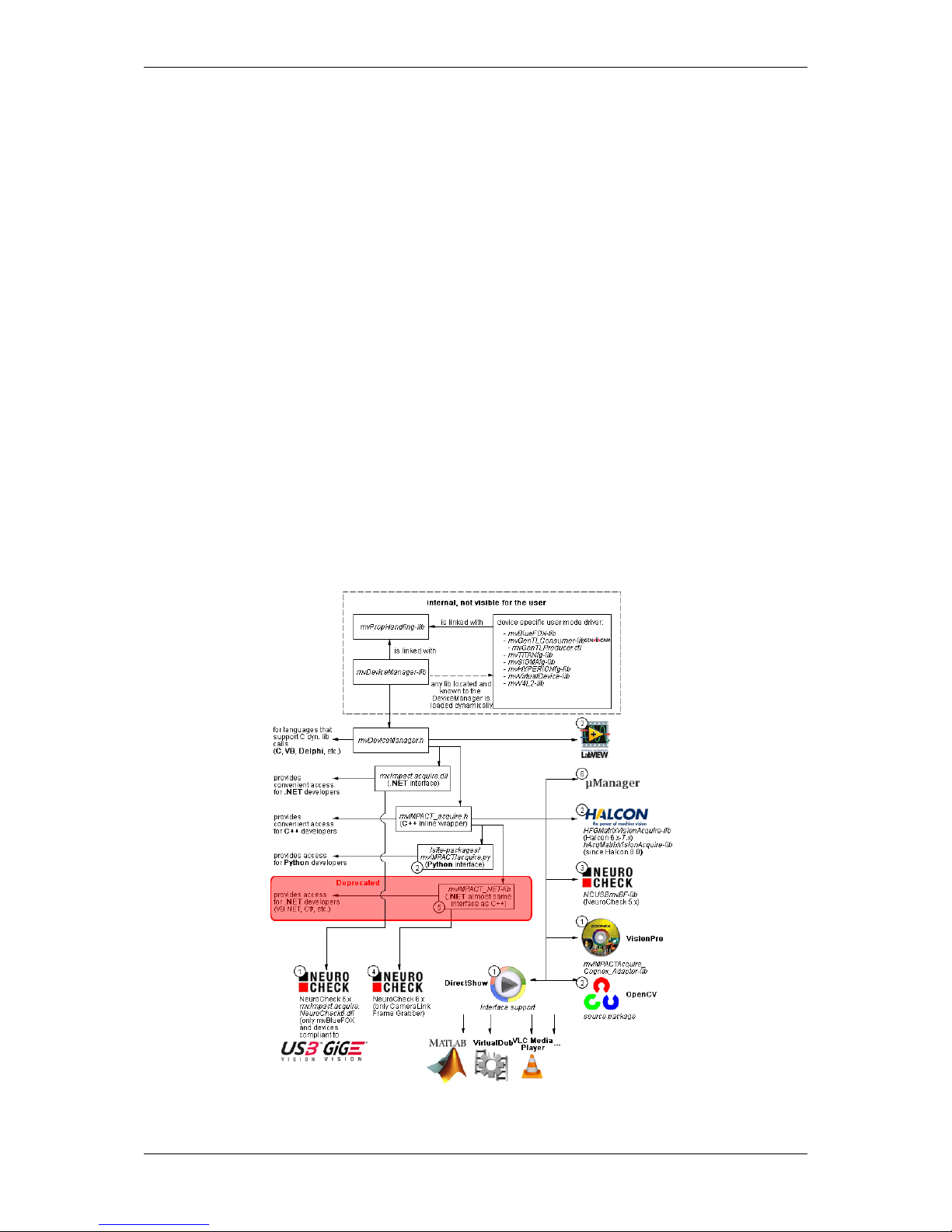
The following diagram shows a schematic structure of the driver concept:
Figure 1: Driver concept
MATRIX VISION GmbH
Page 19
4 CONTENTS
• 1 Part of any mvIMPACT Acquire driver installation package (Windows).
• 2 Separately available for 32 bit and 64 bit. Requires at least one installed driver package.
• 3 See 2, but requires an installed version of the mvBlueFOX driver.
• 4 Part of the NeuroCheck installer but requires at least one installed frame grabber driver.
• 5 Part of the mvIMPACT SDK installation. However, new designs should use the .NET libs that are now part
of mvIMPACT Acquire ("mv.impact.acquire.dll"). The namespace "mv.impact.acquire" of
"mv.impact.acquire.dll" provides a more natural and more efficient access to the same features
as contained in the namespace "mvIMPACT_NET.acquire" of "mvIMPACT_NET.dll", which is why
the latter one should only be used for backward compatibility but NOT when developing a new application.
• 6 Part of Micro-Manager.
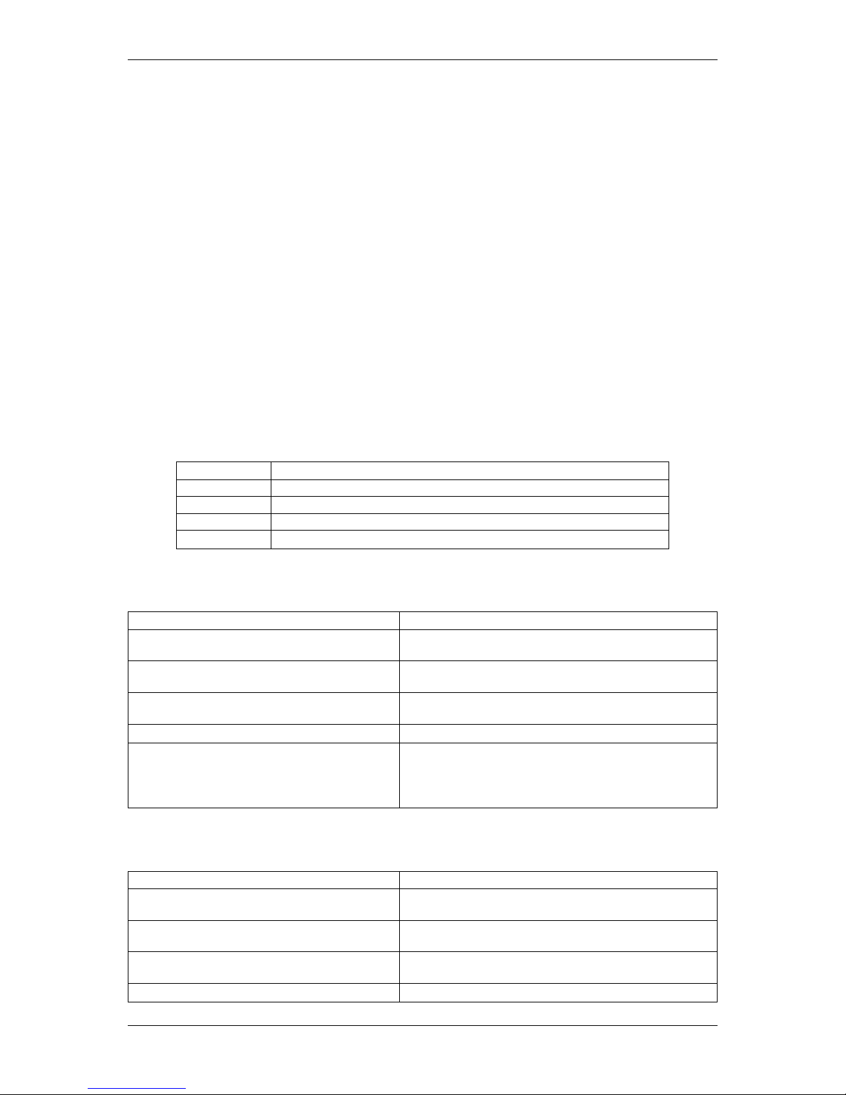
1.2.2.2 NeuroCheck support
A couple of devices are supported by NeuroCheck. However between NeuroCheck 5.x and NeuroCheck 6.x there
has been a breaking change in the internal interfaces. Therefore also the list of supported devices differs from one
version to another and some additional libraries might be required.
For NeuroCheck 5.x the following devices are supported:
Device Additional software needed
mvTITAN-G1 mvSDK driver for mvTITAN/mvGAMMA devices
mvTITAN-CL mvSDK driver for mvTITAN/mvGAMMA devices
mvGAMMA-CL mvSDK driver for mvTITAN/mvGAMMA devices
mvBlueFOX mvIMPACT Acquire driver for mvBlueFOX devices, "NCUSBmvBF.dll"
For NeuroCheck 6.0 the following devices are supported:
Device Additional software needed
mvTITAN-G1 mvIMPACT Acquire driver for mvTITAN/mvGAMMA de-
vices
mvTITAN-CL mvIMPACT Acquire driver for mvTITAN/mvGAMMA de-
vices
mvGAMMA-CL mvIMPACT Acquire driver for mvTITAN/mvGAMMA de-
vices
mvHYPERION-CLb mvIMPACT Acquire driver for mvHYPERION devices
Every other mvIMPACT Acquire compliant device mvIMPACT Acquire driver for the corresponding device
family, "mv.impact.acquire.NeuroCheck6.←-
dll" (comes with the driver package, but the driver
package must be installed AFTER installing NeuroCheck 6
For NeuroCheck 6.1 the following devices are supported:
Device Additional software needed
mvTITAN-G1 mvIMPACT Acquire driver for mvTITAN/mvGAMMA de-
vices
mvTITAN-CL mvIMPACT Acquire driver for mvTITAN/mvGAMMA de-
vices
mvGAMMA-CL mvIMPACT Acquire driver for mvTITAN/mvGAMMA de-
vices
mvHYPERION-CLb mvIMPACT Acquire driver for mvHYPERION devices
MATRIX VISION GmbH
Page 20

1.2 How to get started? 5
Every other mvIMPACT Acquire compliant device mvIMPACT Acquire driver for the corresponding device
family, "mv.impact.acquire.NeuroCheck6_←-
1.dll" (comes with the driver package, but the driver
package must be installed AFTER installing NeuroCheck
6.1
1.2.2.3 VisionPro support
Every mvIMPACT Acquire driver package under Windows comes with an adapter to VisionPro from Cognex. The
installation order does not matter. After the driver package and VisionPro has been installed, the next time VisionPro
is started it will allow selecting the mvIMPACT Acquire device. No additional steps are needed.
MATRIX VISION devices that also comply with the GigE Vision standard don't need any software at all, but can also
use VisionPro's built-in GigE Vision support.
1.2.2.4 HALCON support
HALCON comes with built-in support for mvIMPACT Acquire compliant devices, so once a device driver has been
installed for the mvIMPACT Acquire device, it can also be operated from a HALCON environment using the corresponding acquisition interface. No additional steps are needed.
MATRIX VISION devices that also comply with the GigE Vision standard don't need any software at all, but can also
use HALCON's built-in GigE Vision support.
As some mvIMPACT Acquire device driver packages also come with a GenTL compliant interface, these can also
be operated through HALCON's built-in GenTL acquisition interface.
1.2.2.5 LabVIEW support
Every mvIMPACT Acquire compliant device can be operated under LabVIEW through an additional set of VIs which
is shipped by MATRIX VISION as a separate installation ("mvLabVIEW Acquire").
MATRIX VISION devices that also comply with the GigE Vision or USB3 Vision standard don't need any additional
software at all, but can also be operated through LabVIEW's GigE Vision or USB3 Vision driver packages.
1.2.2.6 DirectShow support
Every mvIMPACT Acquire compliant device driver package comes with an interface to DirectShow. In order to be
usable from a DirectShow compliant application, devices must first be registered for DirectShow support. How to
this is explained here (p.196).
1.2.2.7 Micro-Manager support
Every mvIMPACT Acquire compliant device can be operated under https://micro-manager.org when
using mvIMPACT Acquire 2.18.0 or later and at least Micro-Manager 1.4.23 build AFTER 15.12.2016. The
adapter needed is part of the Micro-Manager release. Additional information can be found here: https←-
://micro-manager.org/wiki/MatrixVision.
1.2.2.7.1 code
• https://valelab4.ucsf.edu/svn/micromanager2/trunk/DeviceAdapters/Matrix←-
Vision/
• https://valelab4.ucsf.edu/trac/micromanager/browser/DeviceAdapters/←-
MatrixVision
MATRIX VISION GmbH
Page 21
6 CONTENTS
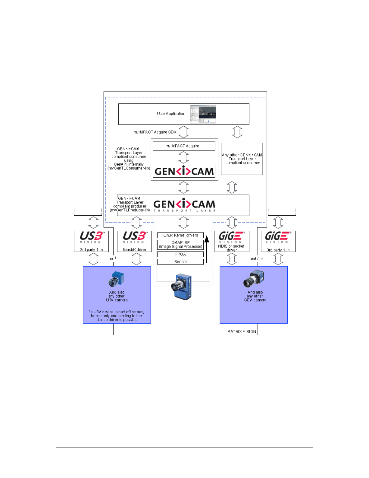
1.2.2.8 Software concept
As shown in Figure 2 the "mvIMPACT Acquire" interface is stacked on the GigE Vision (p. 222) or USB3 Vision
(p. 232) and GenICam (p. 220) layers. The "mvIMPACT Acquire" interface internally uses the GenICam (p. 220)
runtime libs, so that it can be considered as an user application written with the GenICam (p. 220) interface.
Figure 2: Software concept
This behavior has several advantages:
• The mvBlueCOUGAR can be used like any other "mvIMPACT Acquire" device.
• The current version of the mvGenTL-Acquire driver is meant to work with every GigE Vision (p. 222) and
every USB3 Vision (p.232) compliant device.
• Developers either can use the generic GenICam (p. 220) properties or the "mvIMPACT Acquire" properties
when working with a MATRIX VISION device (devices from other vendors can be operated with the "GenI←-
Cam" interface only).
MATRIX VISION GmbH
Page 22

1.2 How to get started? 7
Note
We recommend to work with the GenICam interface layout (p. 135), because as it allows the most flexible
access to the device features.
Please change the property "InterfaceLayout" with wxPropView (p. 109) to select the preferred interface
layout. For more information please have a look at chapter
• Changing interface to GenICam or device specific (p.135), and
• GenICam (p. 220).
1.2.2.9 Image acquisition concept
The image acquisition is based on queues to avoid the loss of single images. With this concept you can acquire
images via single acquisition or triggered acquisition. For detailed description of the acquisition concept, please
have a look at "How the capture process works" in the "mvIMPACT_Acquire_API" manuals.
1.2.3 Installation
To start up the mvBlueCOUGAR properly you have to follow these steps:
(Please follow the links for detailed descriptions.)
• Install driver software.
– Windows (p.39)
– Linux (p.49)
• Start the hardware (p.55).
• Setup the hardware (p.57).
• Install GigE Vision capture filter (p. 142).
• Configure the mvBlueCOUGAR (p. 109)
– e.g. make a white balance (p. 137) (color sensors).
1.2.4 Programming
To control the camera and handle the images, you will have a good introduction by reading the main pages of the
"mvIMPACT Acquire" interface references. Additionally, please have a look at the example programs. Several
basic examples are available. The separate mvIMPACT Acquire manuals
• "mvIMPACT_Acquire_API_CPP_manual.chm",
• "mvIMPACT_Acquire_API_C_manual.chm", and
• "mvIMPACT_Acquire_API_NET_manual.chm"
are available as downloads from our website http://www.matrix-vision.com.
MATRIX VISION GmbH
Page 23

8 CONTENTS
2 Imprint
MATRIX VISION GmbH
Talstrasse 16
DE - 71570 Oppenweiler
Telephone: +49-7191-9432-0
Fax: +49-7191-9432-288
Website: http://www.matrix-vision.de
E-Mail:
info@matrix-vision.de
support@matrix-vision.de
jobs@matrix-vision.de
Author
U. Lansche
Date
2016
This document assumes a general knowledge of PCs and programming.
Since the documentation is published electronically, an updated version may be available online. For this reason we
recommend checking for updates on the MATRIX VISION website.
MATRIX VISION cannot guarantee that the data is free of errors or is accurate and complete and, therefore, assumes no liability for loss or damage of any kind incurred directly or indirectly through the use of the information of
this document.
MATRIX VISION reserves the right to change technical data and design and specifications of the described products
at any time without notice.
Copyright
MATRIX VISION GmbH. All rights reserved. The text, images and graphical content are protected by copyright
and other laws which protect intellectual property. It is not permitted to copy or modify them for trade use or
transfer. They may not be used on websites.
• Windows® XP, Windows® Vista, Windows® 7 are trademarks of Microsoft, Corp.
• Linux® is a trademark of Linus Torvalds.
• GenICam™ is a trademark of the GenICam™ standard group.
• GigE Vision™ and the distinctive logo are trademarks owned by the Automated Imaging Association and may
only be used under license for compliant products registered with the AIA.
All other product and company names in this document may be the trademarks and tradenames of their
respective owners and are hereby acknowledged.
The manual has been generated with Doxygen (Website: http://www.doxygen.org).
Parts of the log file creation and the log file display make use of Sarissa (Website: http://dev.←-
abiss.gr/sarissa) which is distributed under the GNU GPL version 2 or higher, GNU LGPL version
2.1 or higher and Apache Software License 2.0 or higher. The Apache Software License 2.0 is part of this
driver package.
MATRIX VISION GmbH
Page 24

3 Legal notice 9
3 Legal notice
3.1 Introduction
The firmware running on mvBlueCOUGAR-X, mvBlueCOUGAR-XD and mvBlueFOX3 devices make use of a
couple of third party software packages that come with various licenses. This section is meant to list all these
packages and to give credit to those whose code helped in the creation of this software.
3.2 cJSON
A slightly modified version of cJSON (http://sourceforge.net/projects/cjson/) is used inside
some of the modules that eventually build up the firmware.
3.2.1 cJSON license
Copyright (c) 2009 Dave Gamble
Permission is hereby granted, free of charge, to any person obtaining a copy
of this software and associated documentation files (the "Software"), to deal
in the Software without restriction, including without limitation the rights
to use, copy, modify, merge, publish, distribute, sublicense, and/or sell
copies of the Software, and to permit persons to whom the Software is
furnished to do so, subject to the following conditions:
The above copyright notice and this permission notice shall be included in
all copies or substantial portions of the Software.
THE SOFTWARE IS PROVIDED "AS IS", WITHOUT WARRANTY OF ANY KIND, EXPRESS OR
IMPLIED, INCLUDING BUT NOT LIMITED TO THE WARRANTIES OF MERCHANTABILITY,
FITNESS FOR A PARTICULAR PURPOSE AND NONINFRINGEMENT. IN NO EVENT SHALL THE
AUTHORS OR COPYRIGHT HOLDERS BE LIABLE FOR ANY CLAIM, DAMAGES OR OTHER
LIABILITY, WHETHER IN AN ACTION OF CONTRACT, TORT OR OTHERWISE, ARISING FROM,
OUT OF OR IN CONNECTION WITH THE SOFTWARE OR THE USE OR OTHER DEALINGS IN
THE SOFTWARE.
3.3 Unity
A slightly modified version of Unity (https://github.com/ThrowTheSwitch/Unity) is used for unit testing various modules that eventually build up the firmware.
3.3.1 Unity license
Copyright (c) 2007-2010 Mike Karlesky, Mark VanderVoord, Greg Williams
Permission is hereby granted, free of charge, to any person
obtaining a copy of this software and associated documentation
files (the "Software"), to deal in the Software without
restriction, including without limitation the rights to use,
copy, modify, merge, publish, distribute, sublicense, and/or sell
copies of the Software, and to permit persons to whom the
Software is furnished to do so, subject to the following
conditions:
The above copyright notice and this permission notice shall be
included in all copies or substantial portions of the Software.
MATRIX VISION GmbH
Page 25

10 CONTENTS
The end-user documentation included with the redistribution, if
any, must include the following acknowledgment: "This product
includes software developed for the Unity Project, by Mike Karlesky,
Mark VanderVoord, and Greg Williams and other contributors", in
the same place and form as other third-party acknowledgments.
Alternately, this acknowledgment may appear in the software
itself, in the same form and location as other such third-party
acknowledgments.
THE SOFTWARE IS PROVIDED "AS IS", WITHOUT WARRANTY OF ANY KIND,
EXPRESS OR IMPLIED, INCLUDING BUT NOT LIMITED TO THE WARRANTIES
OF MERCHANTABILITY, FITNESS FOR A PARTICULAR PURPOSE AND
NONINFRINGEMENT. IN NO EVENT SHALL THE AUTHORS OR COPYRIGHT
HOLDERS BE LIABLE FOR ANY CLAIM, DAMAGES OR OTHER LIABILITY,
WHETHER IN AN ACTION OF CONTRACT, TORT OR OTHERWISE, ARISING
FROM, OUT OF OR IN CONNECTION WITH THE SOFTWARE OR THE USE OR
OTHER DEALINGS IN THE SOFTWARE.
MATRIX VISION GmbH
Page 26

4 Revisions 11
4 Revisions
Date Rev. Description Driver / Firmware version
14. August 2017 V4.35 Updated sensors mvBlueCOUGA←-
R-Xx02b (1.2 Mpix [1280 x 960])
(p. 570) and mvBlueCOUGAR-←-
Xx02d (1.2 Mpix [1280 x 960])
(p. 574) .
17. July 2017 V4.35 Added Working with the serial in-
terface (mv Serial Interface Control) (p.370) .
Firmware: 2.22.883.0
02. June 2017 V4.34 Updated mvIPConfigure (p. 145) .
29. May 2017 V4.33 Added sensors mvBlueCOUGA←-
R-X100f (0.4 Mpix [1456 x 1088])
(p. 535)
mvBlueCOUGAR-X102f (1.6 Mpix
[1456 x 1088]) (p. 538) .
15. May 2017 V4.32 Updated use case Working with
burst mode buffer (p. 252).
03. May 2017 V4.31 Added use case Working with binning (p. 304).
20. March 2017 V4.30 Updated frame rates of E2V sensors.
Added description of the wizard in
Working with multiple AOIs (mv
Multi Area Mode) (p. 248).
14. February 2017 V4.29 Added Working with multiple AOIs
(mv Multi Area Mode) (p. 248) .
Firmware: 2.18.651.0
13. February 2017 V4.28 Added Implementing a hardware-
based binarization (p. 353) .
24. January 2017 V4.27 Added Error code list (p. 208).
21. December 2016 V4.26 Updated Setting up multiple dis-
play support and/or work with
several capture settings in parallel (p. 125).
Firmware: 2.16.587.0
15. December 2016 V4.25 Added Micro-Manger in Driver con-
cept (p. 3).
Firmware: 2.15.578.0
07. December 2016 V4.24 Updated frame rates of sensors
mvBlueCOUGAR-X[D]109b (8.←-
9 Mpix [4112 x 2176]) (p. 559)
and mvBlueCOUGAR-X[D]1012b
(12.4 Mpix [4112 x 3008]) (p. 561) .
Updated the Secquencer Mode
(p. 240) description including the
new wizard.
01. December 2016 V4.23 Added use case Using the Smart←-
FrameRecall feature (p. 255).
Firmware: 2.15.544.0
26. October 2016 V4.22 Updated sensor characteristics.
23. August 2017 V4.21 Added mv Defective Pixel Correc-
tion Control (p.184).
Firmware: 2.12.406.0
MATRIX VISION GmbH
Page 27

12 CONTENTS
04. August 2016 V4.20 Added sensor IMX267: mvBlueC←-
OUGAR-X[D]109b (8.9 Mpix [4112
x 2176]) (p. 559) .
Added sensor IMX304: mvBlue←-
COUGAR-X[D]1012b (12.4 Mpix
[4112 x 3008]) (p. 561) . .
01. August 2016 V4.19 Added Triggered frame burst
mode (p. 254).
24. June 2016 V4.18 Updated use case Creating acquisition sequences (Sequencer
Control) (p.240).
21. June 2016 V4.17 Added use case Triggering of an
indefinite sequence with precise
starting time (p. 326).
17. June 2016 V4.16 Added use case Synchronizing
camera timestamps without IEEE
1588 (p. 367).
05. April 2016 V4.15 Updated chapter Introducing multicasting (p. 373).
11. February 2016 V4.14 Changed storage and turn-off time
of Characteristics of the digital in-
puts (p. 77) (mvBlueCOUGAR-X-←-
POE-I).
22. January 2016 V4.13 Added sensor mvBlueCOUGAR-←-
Xx04i (3.2 Mpix [2064 x 1544])
(p. 549).
Added sensor mvBlueCOUGAR-←-
Xx05b (5.1 Mpix [2464 x 2056])
(p. 555).
19. January 2016 V4.12 Changed resolution of mvBlueCO←-
UGAR-XD1212a (12.1 Mpix [4248 x
2836]) (p. 525) from 4250 x 2838 pix-
els to 4248 x 2836 pixels.
02. December 2015 V4.11 Updated CE declarations (p.28).
30. November 2015 V4.10 Added Minimizing sensor pat-
tern of mvBlueCOUAGR-X1010G
(p. 309).
Firmware: 2.3.70.0
27. October 2015 V4.09 Added Command-line options
(p. 141).
22. October 2015 V4.08 Added sensor IMX250: mvBlueC←-
OUGAR-XD105a (5.1 Mpix [2464 x
2056]) (p. 552).
25. September 2015 V4.07 Added mvBlueCOUGAR-3X (p. 87)
.
Updated Composition of the man-
ual (p. 2).
07. September 2015 V4.06 Changed sensor size of 10 Mpixels
resolution CMOS sensor (-x010)
(p. 98) from 1/2.35" to 1/2.3".
011. August 2015 V4.05 Added color of KS-BCXD-HR12 in
Circular connector female (p.81).
04. August 2015 V4.04 Added Windows 10 support.
09. July 2015 V4.03 Added chapter I cannot focus on
distant objects (p. 206).
MATRIX VISION GmbH
Page 28

4 Revisions 13
25. June 2015 V4.02 Added note in about using mv←-
BlueCOUGAR-XD with two or one
LAN (RJ 45) connections (p. 55).
23. June 2015 V4.01 Added use case Working with
Event Control (p.266).
19. June 2015 V4.00 Restructured chapter Use cases
(p. 233).
08. June 2015 V3.54 Updated dimensional drawings in
Technical data (p. 64).
21. May 2015 V3.53 Updated pixel clock of mvBlueC←-
OUGAR-XD104d (2.4 Mpix [1936
x 1216]) (p. 542) and mvBlueC←-
OUGAR-Xx04f (2.4 Mpix [1936 x
1216]) (p. 545).
17. April 2015 V3.52 Adapted the sensor resolution of
mvBlueCOUGAR-XD104d (2.4
Mpix [1936 x 1216]) (p. 542) and
mvBlueCOUGAR-Xx04f (2.4 Mpix
[1936 x 1216]) (p. 545).
Firmware: 1.6.366.0
16. April 2015 V3.51 Updated supported Windows versions. Extended the list of sensors
which supports the Creating ac-
quisition sequences (Sequencer
Control) (p.240).
Driver: 2.12.2; Firmware: 1.6.←-
360.0
12. April 2015 V3.50 Removed sensor -XD1212.
31. March 2015 V3.49 Added line scan frame rate calculator for the sensors mvBlueC←-
OUGAR-Xx02e (1.3 Mpix [1280 x
1024]) (p. 578), mvBlueCOUGARXx02eGE (1.3 Mpix [1280 x 1024])
(p. 584), and mvBlueCOUGAR-←-
Xx04e (1.9 Mpix [1600 x 1200])
(p. 591).
25. March 2015 V3.48 Upgraded frame rate calculator of
mvBlueCOUGAR-XD104d (2.4
Mpix [1936 x 1216]) (p. 542) and
mvBlueCOUGAR-Xx04f (2.4 Mpix
[1936 x 1216]) (p. 545).
11. March 2015 V3.47 Added chapter Accessing log files
(p. 134).
05. March 2015 V3.46 Added sensor mvBlueCOUGAR-←-
Xx04f (2.4 Mpix [1936 x 1216])
(p. 545).
04. March 2015 V3.45 Added use case Using Action
Commands (p. 380).
27. February 2015 V3.44 Updated pixel clock for sensors
mvBlueCOUGAR-XD129a (9.2
Mpix [3384 x 2712]) (p. 515) and
mvBlueCOUGAR-XD126a (6 Mpix
[2752 x 2208]) (p. 495).
26. February 2015 V3.43 Added note in I cannot use mv←-
BlueCOUGAR-XD (p. 201) and I
cannot initialize 4 Tap sensor
mvBlueCOUGAR-XDs (p. 202) .
Moved Optimizing the bandwidth
(p. 299) to Use Cases.
MATRIX VISION GmbH
Page 29

14 CONTENTS
09. February 2015 V3.42 Updated pixel clock of mvBlueC←-
OUGAR-XD104d (2.4 Mpix [1936 x
1216]) (p. 542).
02. February 2015 V3.41 Added pinning of KS-BCX-HR12 in
Circular connector male (p.67).
Driver: 2.11.9; Firmware: 1.6.←-
295.0
27. January 2015 V3.40 Added note to use case Using V←-
LC Media Player (p.258). Renewed
Order code nomenclature (p.35).
07. January 2015 V3.39 Extended the description of Disabling the heartbeat (p. 364).
08. December 2014 V3.38 Added use case Adjusting sensor -x02e (-1013) / -x04e (-1020)
(p. 345).
Added further lens in Using motor-
ized lenses with mvBlueCOUGA←-
R-XD (p. 333).
04. December 2014 V3.37 Optimized chapter Quickstart
(p. 39).
02. December 2014 V3.36 Added Quick Setup Wizard
(p. 110).
Driver: 2.11.3; Firmware: 1.6.←-
230.0.
19. November 2014 V3.35 Added use case Using motorized
lenses with mvBlueCOUGAR-XD
(p. 333).
21. October 2014 V3.34 Added description about the record
mode in How to see the first image
(p. 114).
01. October 2014 V3.33 Created a separate mvBlueCOUG←-
AR-X-POE-I chapter: mvBlueCO←-
UGAR-X-POE-I (p. 75).
25. September 2014 V3.32 Added some power consumption
data for mvBlueCOUGAR-XD sensors in Standard model (-xx1x)
(p. 64).
10. September 2014 V3.31 Updated Standard model (-xx1x)
(p. 64).
18. August 2014 V3.30 Added Legal notice (p. 9).
Added Example circuit 3: Control
motorized lens with mvBlueCO←-
UGAR-X (p. 73).
30. July 2014 V3.29 Added sensor -XD1212.
Added sensor mvBlueCOUGAR-←-
XD1212a (12.1 Mpix [4248 x 2836])
(p. 525)
17. July 2014 V3.28 Added use case Introducing LUTs
(p. 347).
05. June 2014 V3.27 Update chapter Using the linescan
mode (p. 261).
15. May 2014 V3.26 Updated data of mvBlueCOUGA←-
R-XD specific CCD sensors (p. 95)
and added -XD126a (p. 495), -X←-
D129a (p. 515), and "-XD1212".
25. March 2014 V3.25 Added use case Correcting image
errors of a sensor (p.268).
MATRIX VISION GmbH
Page 30

4 Revisions 15
17. Mar. 2014 V3.24 Updated length of mvBlueCOUG←-
AR-XD in Standard model (-xx1x)
(p. 79).
10. Mar. 2014 V3.23 mvDeviceConfigure (p. 149) extended.
25. Feb. 2014 V3.22 Added note in Configure a GigE Vi-
sion device (p.146).
18. Feb. 2014 V3.21 Updated Characteristics (p. 577) of
mvBlueCOUGAR-Xx02d (1.2 Mpix
[1280 x 960]) (p. 574).
17 Feb. 2014 V3.20 Added use case Detecting overtrig-
gering (p. 321).
12 Feb. 2014 V3.19 Updated trigger modes of the sen-
sors.
Updated figure 1 in Standard model
(-xx1x) (p. 64).
Added declaration of conformity
(p. 28) of mvBlueCOUGAR-X-POE-I.
10 Feb. 2014 V3.18 Updated length of mvBlueCOUGAR-
XD Standard model (-xx1x) (p.79).
30 Jan. 2014 V3.17 Added note to Video iris (p. 86) sec-
tion.
Added 2 troubeshooting sections←-
: I cannot use mvBlueCOUGAR-←-
XD (p. 201) and I cannot initialize 4
Tap sensor mvBlueCOUGAR-XDs
(p. 202).
28 Jan. 2014 V3.16 Added use case Working with
Sony's 4 Tap CCD sensors
(p. 306).
Added Video iris (p. 86) pinning.
Rearranged chapter Technical data
(p. 64).
Added networking restart command
line in Additional network config-
uration for mvBlueCOUGAR-XD
(p. 53).
22 Jan. 2014 V3.15 New sensors mvBlueCOUGAR-
X[D]x04 (2.2 Mpix [2048 x 1088])
(p. 597) and mvBlueCOUGARX[D]x04b (4.2 Mpix [2048 x 2048])
(p. 604) for mvBlueCOUGAR-X.
20 Jan. 2014 V3.14 Added use cases Creating acquisi-
tion sequences (Sequencer Control) (p. 240) and Working with
LUTValueAll (p. 351) (which was
originally a part of LUT Control
(p. 174)).
17 Jan. 2014 V3.13 Added POE-I note in For customers
in the U.S.A. (p.33).
8 Jan. 2014 V3.12 Added note in Creating synchro-
nized acquisitions using timers
(p. 386).
MATRIX VISION GmbH
Page 31

16 CONTENTS
20 Dec. 2013 V3.11 Added Sample 2: Triggered line
scan acquisition with a specified number of image blocks and
pausing trigger signals (p. 265)
scan_Sample.
17 Dec. 2013 V3.10 Updated Summary of advanced
features (p. 90) and Summary of
components (p. 89).
16 Dec. 2013 V3.09 Added Power over Ethernet model
(-POE-I) (p. 75).
9 Dec. 2013 V3.08 Update description of firmware up-
date (p. 152).
06. December 2013 V3.07 Added information about Changing
the view of the property grid to assist writing code that shall locate
driver features (p. 133).
22. November 2013 V3.06 Extended information in Adjusting
sensor -x00w (p. 339) and Adjusting sensor -x02d (-1012d) (p. 342).
20. November 2013 V3.05 Extended POE-I model information
in Technical data (p. 64).
06. November 2013 V3.04 Unified power supply specification.
30. October 2013 V3.03 Added I get an exception when
setting offsetX or offsetY (p. 201).
22. October 2013 V3.02 Added declaration of conformity
(p. 28) of mvBlueCOUGAR-XD.
17. October 2013 V3.01 mvBlueCOUGAR-X without hous-
ing (p. 65) is an order option (-xx9x).
15. October 2013 V3.00 Added Webcasts (p. 24) links.
Added chapter Bit-shifting an im-
age (p. 132).
14. October 2013 V2.22 "User Set Default Selector" is deprecated and will be replaced by "User
Set Default".
02. October 2013 V2.21 Added max current consumption of
the digital inputs (p. 68).
27. September 2013 V2.20 Added pinning of Circular connec-
tor male (POE-I Rev. 2.00) (p. 76).
Added pinning of M12 x-coded
100/1000 MBit Ethernet (option
POE-I Rev. 2.00) (p. 79) .
Updated Figure 10.2: DigIn mv←-
BlueCOUGAR-X (PLC option)
(p. 68)
23. September 2013 V2.19 Updated resolution of -XD126 and -
XD129 (p. 95).
17. September 2013 V2.18 Added note about the galvanic
isolation of the Ethernet signals
(p. 73).
12. September 2013 V2.17 Added CMOSIS variants -204 and
-204b in mvBlueCOUGAR-XD
specific CMOS sensors (p. 102).
These models support 30 MHz pixel
clock and 12 bit ADC on the basis of
a firmware variant.
MATRIX VISION GmbH
Page 32

4 Revisions 17
03. September 2013 V2.16 Enhanced sensor listing of Order
code nomenclature (p.35).
Added troubeshooting section I can
see the camera in mvIPConfigure,
but I cannot access the camera
(p. 200).
07. August 2013 V2.15 Changed resolution of sensor
mvBlueCOUGAR-Xx22 (1.←-
2 Mpix [1280 x 960]) (p. 427) from
1290x964 to 1290x960.
19. July 2013 V2.14 Added sensor mvBlueCOUGAR-←-
Xx04e (1.9 Mpix [1600 x 1200])
(p. 591).
17. July 2013 V2.13 Added recommended network interface cards in System requirements
(p. 39).
11. July 2013 V2.12 Added Additional hardware re-
quirements for mvBlueCOUGARXD (p. 39).
25. June 2013 V2.11 Added more links to line scan
mode (p. 261).
20. June 2013 V2.10 Added Additional temperature and
power consumption notes concerning mvBlueCOUGAR-XD and
mvBlueCOUGAR-X2xx (p. 28).
18. June 2013 V2.09 Added bonding description for Linux
systems: Additional network con-
figuration for mvBlueCOUGAR-←-
XD (p. 53).
04. June 2013 V2.08 Added power consumption in Sensor overview (p.93).
03. June 2013 V2.07 Added use case Using VLC Media
Player (p.258).
13. May 2013 V2.06 Changed mvBlueCOUGAR-Xx10 to
mvBlueCOUGAR-Xx010.
26. February 2013 V2.05 Added chapter Relationship be-
tween driver, firmware, FPGA file
and user settings (p. 59).
14. February 2013 V2.04 Corrected overlapping capability of
mvBlueCOUGAR-Xx02e (1.3 Mpix
[1280 x 1024]) (p. 578) and mv←-
BlueCOUGAR-Xx02eGE (1.3 Mpix
[1280 x 1024]) (p. 584).
28. January 2013 V2.03 Added description Working with the
UserFile section (Flash memory)
(p. 359).
24. January 2013 V2.02 Added information about image error counts and disabling CPU sleep
states: Setting up the camera
(p. 57), How to disable CPU sleep
states a.k.a. C states (< Windows
8) (p.156), and There are image error counts (p.200).
MATRIX VISION GmbH
Page 33

18 CONTENTS
19. December 2012 V2.01 Added 2 sensors: mvBlueCO←-
UGAR-Xx02eGE (1.3 Mpix [1280
x 1024]) (p. 584) and mvBlueC←-
OUGAR-Xx010 (10 Mpix [3856 x
2764]) (p. 613).
14. December 2012 V2.00 New version of technical documentation.
07. December 2012 V1.27 All parts of the manual to do with programming are available as a separate manual now:
• "mvIMPACT_Acquire_API←-
_CPP_manual.chm",
• "mvIMPACT_Acquire_API←-
_C_manual.chm", and
• "mvIMPACT_Acquire_API←-
_NET_manual.chm". These
manuals can be download
from http://www.←-
matrix-vision.com.
20. November 2012 V1.26 Corrected trigger description in description of the CCD sensors.
12. November 2012 V1.25 Added mvBlueCOUGAR-XD sensor
mvBlueCOUGAR-XD129 (9.2 Mpix
[3384 x 2712]) (p. 505).
30. October 2012 V1.24 Updated Characteristics of the
digital inputs (p. 68).
22. October 2012 V1.23 Updated Legal notice (p. 33).
19. October 2012 V1.22 Updated sensor data in Sensor
overview (p.93).
25. September 2012 V1.21 Added mvBlueCOUGAR-XD sensors mvBlueCOUGAR-XD124a (3
Mpix [1936 x 1460]) (p. 456) and
mvBlueCOUGAR-XD126 (6 Mpix
[2752 x 2208]) (p. 485).
20. September 2012 V1.20 Added chapter "Porting existing
code written with versions earlier
then 2.0.0 (C++)".
06. September 2012 V1.19 Clarified view of connectors in Technical data (p. 64).
18. August 2012 V1.18 Added mvBlueCOUGAR-XD information in Technical data (p. 64)
Added mvBlueCOUGAR-XD sensor
mvBlueCOUGAR-X[D]x04b (4.2
Mpix [2048 x 2048]) (p. 604).
17. August 2012 V1.17 Added use case Adjusting sensor
-x02d (-1012d) (p. 342).
18. July 2012 V1.16 Added use case Creating a debouncing filter at the inputs
(p. 331).
12. July 2012 V1.15 Added use case Creating user set
entries (p. 357).
MATRIX VISION GmbH
Page 34

4 Revisions 19
09. July 2012 V1.14 Added section Image Data is lost
(incomplete frames) (p.200) in
chapter Troubleshooting (p.200).
06. July 2012 V1.13 Added description about the second
(female) connector of mvBlueC←-
OUGAR-XD (p. 81).
05. July 2012 V1.12 Changed manual structure.
02. July 2012 V1.11 Added uses cases Using the pri-
mary application switchover functionality (p. 391) and
Disabling the heartbeat (p. 364)
.
25. June 2012 V1.10 Corrected frame rate calculator of
mvBlueCOUGAR-Xx02e (1.3 Mpix
[1280 x 1024]) (p. 578)
. Completed spectral characteristics
of (-x02b) (p. 571)
(-x02e) (p. 579)
(-x05) (p. 610)
.
19. June 2012 V1.9 Updated trigger modes summary of
all CCD sensors (p.93) and
(-x00w) (p. 567)
(-x02b) (p. 571)
(-x02d) (p. 575)
(-x02e) (p. 579)
(-x05) (p. 610)
.
12. June 2012 V1.8 Updated digital input characteristics
in chapter Circular connector male
(p. 67).
29. May 2012 V1.7 Updated chapter Introducing multi-
casting (p. 373).
25. May 2012 V1.6 Added chapter Setting a flicker-
free auto expose and auto gain
(p. 301).
07. May 2012 V1.5 Added information about -PLC and POE options in
Order code nomenclature (p.35),
Technical data (p. 64) and
Summary of components (p. 89).
20. April 2012 V1.4 Added chapter Optimizing the
color fidelity of the camera
(p. 282)
Extended chapter Order code
nomenclature (p.35)
Added chapter Cold mirror filter
(p. 107)
Added new sensor mvBlueCO←-
UGAR-X[D]x04 (2.2 Mpix [2048 x
1088]) (p. 597)
Changed length of mvBlueCOU←-
GAR-XD (p. 79)
Added description about the line
scan mode of sensor mvBlueC←-
OUGAR-Xx02e (1.3 Mpix [1280 x
1024]) (p. 578).
MATRIX VISION GmbH
Page 35

20 CONTENTS
02. April 2012 V1.3 Enhanced chapter Output se-
quence of color sensors (RGB
Bayer) (p.104) and
added chapter Bilinear interpolation of color sensors (RGB Bayer)
(p. 105).
13. March 2012 V1.2 Removed note about inverse-polarity
protection, because the digital in-
puts (p. 64) have inverse-polarity
protection in the meantime.
12. March 2012 V1.1 Updated image of Circular connec-
tor male (p. 67)
07. March 2012 V1.0 Update Linux installation section in
Installing the mvGenTL-Acquire
driver (p. 50)
Added use case Generating a
pulse width modulation (PWM)
(p. 314)
Added use case Outputting a
pulse at every other external
trigger (p. 317)
Added use case Reset timestamp
by hardware (p. 366)
Added chapter Troubleshooting
(p. 200)
06. March 2012 V1.0b33 Added chapter GenICam and Ad-
vanced Features (p.160)
Updated description Creating syn-
chronized acquisitions using
timers (p.386)
Added use case Acquiring a number of images (p. 237)
Added use case Controlling strobe
or flash at the outputs (p. 329)
Added use case Working with
burst mode buffer (p. 252)
Added use case Getting a trigger
with an incremental encoder
(p. 312)
Added use case Working with the
temperature sensors (p.362)
Added use case Creating different
exposure times for consecutive
images (p. 318)
Added note about the short circuit
protection of the digital outputs in
Circular connector male (p.67)
23. February 2012 V1.0b32 Updated data of sensors mvBlue←-
COUGAR-Xx05 (5 Mpix [2592 x
1944]) (p. 608)
17. February 2012 V1.0b31 Renewed chapter wxPropView
(p. 109)
09. January 2012 V1.0b30 Added mvBlueCOUGAR-XD in
chapter Technical data (p. 64) and
Introduction (p.35)
MATRIX VISION GmbH
Page 36

4 Revisions 21
06. December 2011 V1.0b29 Added block diagrams of image data
flow in chapter Sensor overview
(p. 93)
09. November 2011 V1.0b28 Added chapter about Settings be-
haviour during startup (p. 58) in
chapter Quickstart (p. 39)
11. October 2011 V1.0b27 Added GenICam (p. 220) specific
trigger setting names in sensor
descriptions (p. 93)
Added Recording sequences with
pre-trigger (p. 238)
Added Reducing noise by frame
averaging (p.296)
05. October 2011 V1.0b26 Added accessory: mvBC-X I/O-B←-
OX (p. 37)
Added digital input and output
delay: Circular connector male
(p. 67)
22. September 2011 V1.0b25 Added sensor: mvBlueCOUGA←-
R-Xx02b (1.2 Mpix [1280 x 960])
(p. 570)
Added sensor: mvBlueCOUGA←-
R-Xx02d (1.2 Mpix [1280 x 960])
(p. 574)
Added sensor: mvBlueCOUGA←-
R-Xx02e (1.3 Mpix [1280 x 1024])
(p. 578)
Added sensor: mvBlueCOUGAR-←-
Xx05 (5 Mpix [2592 x 1944]) (p. 608)
26. July 2011 V1.0b24 Removed chapter
"EventHandling (C++ developers).
See Porting existing code written
with versions earlier then 2.0.0 (←-
C++)"
11. July 2011 V1.0b23 Added chapter "Callback demo"
06. June 2011 V1.0b22 Added chapter "Porting existing
code written with versions earlier
then 2.0.0"
21. April 2011 V1.0b21 Added example circuits for the highside switch: Circular connector
male (p. 67)
14. April 2011 V1.0b20 Added sensor: mvBlueCOUGA←-
R-Xx20d (0.5 Mpix [776 x 580])
(p. 416)
24. March 2011 V1.0b19 Added chapter: Adjusting sensor -
x00w (p. 339)
09. March 2011 V1.0b18 Update sensor area: Sensor
overview (p.93)
18. January 2011 V1.0b17 Added chapter "Porting applica-
tions written with the Generic interface layout to use the GenICam
interface layout"
Setting up multiple display support and/or work with several capture settings in parallel (p. 125)
MATRIX VISION GmbH
Page 37

22 CONTENTS
29. November 2010 V1.0b16 Added ADC resolutions in Sensor
overview (p.93)
25. November 2010 V1.0b15 Added information about Summary
of advanced features (p. 90)
22. November 2010 V1.0b14 Added chapter C: Notes about mv←-
IMPACT Acquire version 1.11.32 or
higher and/or using mvBlueCOUG←-
AR-X with firmware 1.2.0 or higher
18. November 2010 V1.0b13 Added chapter C++: Notes about
mvIMPACT Acquire version 1.11.←-
32 or higher and/or using mvBlue←-
COUGAR-X with firmware 1.2.0 or
higher
19. October 2010 V1.0b12 Added chapter "Chunk data for-
mat"
14. Sep. 2010 V1.0b11 Added chapter Creating synchronized acquisitions using timers
(p. 386)
03. Sep. 2010 V1.0b10 Added IPv4 converter in Introduc-
ing multicasting (p.373)
Corrected integration time of Wide-
VGA resolution CMOS sensor (x00w) (p. 98)
26. Aug. 2010 V1.0b9 Added chapter about Creating user
data entries (p. 355)
04. Aug. 2010 V1.0b8 Added chapter Import and Export
images (p. 124)
Updated sensor data (p. 93)
Added Summary of advanced fea-
tures (p. 90)
30. Jun. 2010 V1.0b7 Added chapter GenICam to mv←-
IMPACT Acquire code generator
(p. 233)
28. Jun. 2010 V1.0b6 Added information about module
version mvBlueCOUGAR-XM Tech-
nical data (p. 64)
21. Jun. 2010 V1.0b5 Included exposure modes in the
frame rate calculator of the Sensor
overview (p.93)
Added detailed information to info←-
TimeStamp_us of the "Request
Class"
15. Jun. 2010 V1.0b4 Added note about Digital Input
(p. 64) and updated the Digital Input
figure
28. May 2010 V1.0b3 Added new example Single←-
CaptureMasterSlave
27. Apr. 2010 V1.0b2 Added chapter Saving user set-
tings in the non-volatile flash
memory (p.140), which shows how
to work with user sets
MATRIX VISION GmbH
Page 38

4 Revisions 23
27. Apr. 2010 V1.0b1 Added chapter "Building, linking and
running applications using mvIMP←-
ACT Acquire", which shows how to
run an application that has been built
using the mvIMPACT Acquire framework
19. Apr. 2010 V1.0b Added new example Continuous←-
CaptureDirectX
15. Apr. 2010 V1.0b Updated mvBlueCOUGAR-X technical documentation
24. Mar. 2010 Updated Sensor overview (p. 93)
(Frame rate calculator of -x20a, x20b, -x22, -x23, -x00w)
15. Mar. 2010 Updated What's inside and acces-
sories (p. 37)
Added dimensional drawing of tri-
pod adapter (p. 67)
29. Jan. 2010 Added sensor CCD - 1360x1024
pixels (-x23) (p. 436)
28. Jan. 2010 Added chapter Copy grid data to
the clipboard (p.123)
27. Jan. 2010 Added chapter Introducing multi-
casting (p. 373)
25. Jan. 2010 Updated digital in figure of Hirose
12-pin male connector (p. 67)
Updated description of Hot mirror
filter (p. 107)
20. Jan. 2010 Updated pinning and digital out figure of Hirose 12-pin male connec-
tor (p. 67)
12. Jan. 2010 Due to a software update, documentation of CMOS sensor (-x00w)
(p. 566) updated
November 2009 Initial version
MATRIX VISION GmbH
Page 39

24 CONTENTS
5 Graphic Symbols
5.1 Notes, Warnings, Attentions
Note
A note indicates important information that helps you optimize usage of the products.
Warning
A warning indicates how to avoid either potential damage to hardware or loss of data.
Attention
An attention indicates a potential for property damage, personal injury, or death.
All due care and attention has been taken in preparing this manual. In view of our policy of continuous product
improvement, however, we can accept no liability for completeness and correctness of the information contained in
this manual. We make every effort to provide you with a flawless product.
In the context of the applicable statutory regulations, we shall accept no liability for direct damage, indirect damage
or third-party damage resulting from the acquisition or operation of a MATRIX VISION product. Our liability for intent
and gross negligence is unaffected. In any case, the extend of our liability shall be limited to the purchase price.
5.2 Webcasts
This icon indicates a webcast about an issue which is available on our website.
MATRIX VISION GmbH
Page 40

6 Important information 25
6 Important information
6.1 Important safety instructions
• We cannot and do not take any responsibility for the damage caused to you or to any other equipment
connected to the mvBlueCOUGAR-X . Similarly, warranty will be void, if a damage is caused by not following
the manual.
• Handle the mvBlueCOUGAR-X with care. Do not misuse the mvBlueCOUGAR-X . Avoid shaking, striking,
etc. The mvBlueCOUGAR-X could be damaged by faulty handling or shortage.
• Do not use accessories not recommended by the product manufacturer as they may cause hazards.
• The product should be situated away from heat sources such as radiators, heat registers, stoves, or other
products (including amplifiers) that produce heat.
• Using the board-level version:
– Provide sufficient cooling because single components can reach high temperatures.
– Handle with care and avoid damage of electrical components by electrostatic discharge (ESD):
*
Discharge body static (contact a grounded surface and maintain contact).
*
Avoid all plastic, vinyl, and styrofoam (except antistatic versions) around printed circuit boards.
*
Do not touch components on the printed circuit board with your hands or with conductive devices.
6.2 Operating considerations
6.2.1 Important safety notes
• Use this camera with a 12V to 24V DC power supply (+- 1V).
• Using the Model without housing (-xx9x) (p. 65) :
– Provide sufficient cooling because single components can reach high temperatures. Inadequate and
incorrect cooling invalidate the guarantee.
• For extended temperature (-ET) models:
–
Warning
In general, the housing temperature of the ET models must not exceed 65°C!
• Observe that flammable objects, water or metal do not enter the camera interior. These may lead to failure or
accident.
• Do not modify the camera or use the camera with external covers removed. These may cause failure, void
any warranties and pose a safety hazard.
• Stop using the camera at the approach of electrical storm (thunder audible). Protect the camera from rain if
using it outdoors.
• In the event of abnormal functioning, switch off the camera and disconnect the power cord. Contact MATRIX
VISION.
MATRIX VISION GmbH
Page 41

26 CONTENTS
6.2.2 Handling and cleaning
• Do not attempt to disassemble camera.
• When installing or removing a lens, take care that water or dust does not enter the inside of the camera.
6.2.3 Installing
Avoid installing or storing the camera in the following environments:
• Environments exposed to direct sunlight, rain or snow.
• Environments where combustible or corrosive gas exists.
• Excessively warm or cold environment (Operating ambient temperature: 0 to 45 °C)
• Humid or dusty environment.
• Place subjected to excessive vibration or shock.
• Environment exposed to strong electric or magnetic field.
• It is recommended to mount the camera on a thermoconducting surface such as aluminum or other metals
rather than plastic or wood.
• Please contact manufacturer or local distributor if you want to use additional enclosures for higher ingress
protection.
• Do not aim the camera lens at the sun or other very strong light sources.
"CCD phenomenon: Smearing": Vertical smearing may appear, in the image. However, this is not due to failure
of the camera.
6.2.4 Optimizing performance and life time
When the camera is used continuously for long time under high ambient temperature, the inside electrical parts may
deteriorate, resulting in shorter life span. Additional cooling by e.g. air convection is recommended.
6.2.5 Connectors
Confirm the power is off before connecting or disconnecting a signal cable. Grasp connectors by the body, not the
attached wires.
6.2.6 Cleaning
• Use a blower or a lens brush to remove dust on the lens or the optical filter.
• Do not disassemble front flange.
• Clean case with dry soft cloth. Use neutral detergent liquid if needed; wipe the cover with dry cloth.
• Do not use benzene, thinner, alcohol, liquid cleaner or spray-type cleaner.
• If dust or other debris is located between the CCD and optical filter, consult dealer for cleaning by an optical
technician.
MATRIX VISION GmbH
Page 42

6.2 Operating considerations 27
6.2.7 Adjusting the C-mount
The mvBlueCOUGAR-Xcameras allow a precise adjustment of the back focus of the C-mount by means of a back
focus ring which is threaded into the C-mount and is secured by a lock nut ring which itself is secured by two screws.
The mechanical adjustment of the imaging device is important in order to achieve a perfect alignment with the focal
point of the lens. This adjustment is made before leaving the factory to conform to the standard of 17.526 mm (in
air) and should normally not require adjustment in the field. However, if the back focal plane of your lens does not
conform to the C-mount back focus specification or if you have e.g. removed the IR-CUT filter (p. 107), renewed
adjustment may be required.
Figure 1: Lensholder with C-mount ring (1) and lock nut ring (2)
How to proceed:
• Loosen screws (location as shown above by arrows) of the lock nut ring with an Allen key (0.9 x 50).
• Loosen the lock nut ring.
• With the lens set to infinity or a known focus distance, set the camera to view an object located at "infinity" or
the known distance.
• Rotate the C-mount ring and lens forward or backwards on its thread until the object is in sharp focus.
Note
Be careful that the lens remains seated in the C-mount.
• Once focus is achieved, tighten the lock nut ring, then tighten the two locking screws of the lock ring without
applying excessive torque.
MATRIX VISION GmbH
Page 43

28 CONTENTS
6.2.8 Additional temperature and power consumption notes concerning mvBlueCOUGAR-XD and mvBlueCOUGAR-X2xx
mvBlueCOUGAR-XD and mvBlueCOUGAR-X2xx cameras have very different power consumptions depending on
sensor technology and connection and operation modes. As a rule of thumb:
• CMOS sensor camera with single network interface controller (NIC) output consumes less around 4W
• CCD equipped cameras with quad tap use and dual NIC output and max. pixel clock may consume up to 9W
• CCD sensor dual tap mode consumes 1.7W less than quad tap
• For mvBlueCOUGAR-XD: Dual NIC mode (so-called link aggregation [LAG] or bonding (p. 223)) consumes
0.8W more than single NIC used
Data sheets of cameras commonly specify the allowed temperature range by indicating the min/max. ambient
temperature of the air (e.g in a room) where the camera is installed and operated. Whereas this is good for a first
indication and comparison it presents a fuzziness for the temperature of the components inside because it is not
defined how the camera is mounted and thus the overtemperature inside the camera is not clear.
And since each installation is different, MATRIX VISION cannot supply a strictly required procedure for proper heat
dissipation. Instead, we provide the following general guidelines:
In all cases,
1. you should monitor the temperature of the camera by using the two built-in temperature sensors (separate for
sensor board and mainboard) and
2. make sure that neither the sensor temperature nor the mainboard temperature exceed 75 °C.
Keep in mind that the camera will gradually heat up during the first hour of operation. After one hour, the housing
temperature should have stabilized and increases no longer.
• If your camera is mounted on a substantial metal holder or component in your system, this may already
provide sufficient heat dissipation because this metal component presents a low thermal resistance for the
heat path.
• You may use additional heat conductors between the camera and the holder to bridge gaps.
• The use of a fan to provide air flow over the camera is an extremely efficient method of heat dissipation.
The fan can be driven directly by one of the robust camera outputs and controlled by the camera itself (temp. settings
to switch fan on and off with hysteresis) as long as
• the switched voltage at the output is suitable for the used fan (12V up to 24V) and that
• the fan does not consume more than 700 mA which is the maximum one output of the camera can deliver.
Available CPU Socket 7 (370 or socket A) active cooler fit very well directly on any side of the camera by means of
thermal glue. Ask for support if you need further assistance.
6.3 European Union Declaration of Conformity statement
MATRIX VISION GmbH
Page 44

6.3 European Union Declaration of Conformity statement 29
The mvBlueCOUGAR-X is in conformity with all applicable essential requirements
necessary for CE marking. It corresponds to the EU EMC guideline 2014/30/EU based
on the following harmonized standards Electromagnetic compatibility (EMC)
• Interference emmision EN 61000-6-3 / 2007
• Interference emmision EN 61000-6-4 / 2007 for mvBlueCOUGAR-X PoE (p. 229)
version
• Interference immunity EN 61000-6-2 / 2005
EN 61000-6-3 / 2007 requires an I/O cable with an retrofittable ferrite to be
used such as
– Company: Würth Elektronik Type: WE No. 742 711 31
MATRIX VISION corresponds to the EU guideline WEEE 2002/96/EG on waste electrical
and electronic equipment and is registered under WEEE-Reg.-No. DE 25244305.
RoHS All units delivered are RoHS compliant.
IP30 mvBlueCOUGAR-X / mvBlueCOUGAR-XD / mvBlueCOUGAR-X -POE (p. 35)
IP50 mvBlueCOUGAR-X -POE-I (p. 35)
IP67 mvBlueCOUGAR-X -POE-IP67 (p. 35)
PoE 802.3at (p.229) The option -POE (p. 35) is compliant to IEEE 802.3af (IEEE 802.3at Type 1).
MATRIX VISION GmbH
Page 45

30 CONTENTS
MATRIX VISION GmbH
Page 46

6.3 European Union Declaration of Conformity statement 31
MATRIX VISION GmbH
Page 47

32 CONTENTS
MATRIX VISION GmbH
Page 48

6.4 Legal notice 33
6.4 Legal notice
6.4.1 For customers in the U.S.A.
MATRIX VISION GmbH
Page 49

34 CONTENTS
Class B
Class A (mvBlueCOUGAR-X PoE (p.229) and POE-I version)
This equipment has been tested and found to comply with the limits for a Class B digital device, pursuant to Part
15 of the FCC Rules. These limits are designed to provide reasonable protection against harmful interference
when the equipment is operated in a residential environment. This equipment generates, uses, and can radiate
radio frequency energy and, if not installed and used in accordance with the instruction manual, may cause harmful
interference to radio communications. However there is no guarantee that interferences will not occur in a particular
installation. If the equipment does cause harmful interference to radio or television reception, the user is encouraged
to try to correct the interference by one or more of the following measures:
• Reorient or relocate the receiving antenna.
• Increase the distance between the equipment and the receiver.
• Use a different line outlet for the receiver.
• Consult a radio or TV technician for help.
You are cautioned that any changes or modifications not expressly approved in this manual could void your authority
to operate this equipment. The shielded interface cable recommended in this manual must be used with this
equipment in order to comply with the limits for a computing device pursuant to Subpart B of Part 15 of FCC Rules.
• FCC Class B requires an I/O cable with an retrofittable ferrite to be used such as
– Company: Würth Elektronik Type: WE No. 742 711 31
6.4.2 For customers in Canada
This apparatus complies with the Class B limits for radio noise emissions set out in the Radio Interference Regulations.
6.4.3 Pour utilisateurs au Canada
Cet appareil est conforme aux normes classe B pour bruits radioélectriques, spécifiées dans le Règlement sur le
brouillage radioélectrique.
MATRIX VISION GmbH
Page 50

7 Introduction 35
7 Introduction
The mvBlueCOUGAR is an extreme compact and flexible industrial Gigabit Ethernet camera family compliant to
GigE Vision (p. 222) and GenICam (p. 220). The Gigabit Ethernet interface transfers high data rates over long
distances using inexpensive standard network parts. A Dual-GigE version named mvBlueCOUGAR-XD is also
available. The cameras allow an easy integration in the environment and support the application with helpful features
to deliver faster and better results.
Figure 1: mvBlueCOUGAR-X
The mvBlueCOUGAR-X is also available without housing.
7.1 Order code nomenclature
7.1.1 mvBlueCOUGAR-X
The mvBlueCOUGAR-X nomenclature scheme is as follows:
mvBlueCOUGAR-X - A B C - D - (1) (2) (3) (4) E
- A: Sensor model
120a: 0.3 Mpix, 640 x 480, 1/3", CCD
120b: 0.3 Mpix, 640 x 480, 1/3", CCD
100f: 0.4 Mpix, 728 x 544, 1/2.9", CMOS
100w: 0.4 Mpix, 752 x 480, 1/3", CMOS
120d: 0.5 Mpix, 776 x 580, 1/2", CCD
102b: 1.2 Mpix, 1280 x 960, 1/3", CMOS
102d: 1.2 Mpix, 1280 x 960, 1/3", CMOS
122: 1.2 Mpix, 1280 x 960, 1/3", CCD
102e: 1.3 Mpix, 1280 x 1024, 1/1.8", CMOS
102f: 1.6 Mpix, 1456 x 1088, 1/2.9", CMOS
123: 1.4 Mpix, 1360 x 1024, 1/2", CCD
124: 1.9 Mpix, 1600 x 1200, 1/1.8", CCD
104e: 1.9 Mpix, 1600 x 1200, 1/1.8", CMOS
104: 2.2 Mpix, 2048 x 1088, 2/3", CMOS
104f: 2.4 Mpix, 1936 x 1214, 1/1.2", CMOS
104i: 3.2 Mpix, 2064 x 1544, 1/1.8", CMOS
104b: 4.2 Mpix, 2048 x 2048, 1", CMOS
104bUV: 4.2 Mpix, 2048 x 2048, 1", CMOS
105: 5.0 Mpix, 2592 x 1944, 1/2.5", CMOS
105b: 5.1 Mpix, 2464 x 2056, 2/3", CMOS
125a: 5.1 Mpix, 2448 x 2050, 2/3", CCD
225: 5.1 Mpix, 2448 x 2050, 2/3", CCD
109b: 8.9 Mpix, 4112 x 2176, 1", CMOS
1010: 10.7 Mpix, 3856 x 2764, 1/2.35", CMOS
1012b: 12.4 Mpix, 4112 x 3008, 1.1", CMOS
- B: Sensor color
G: Gray scale version
C: Color version
- C: Infrared enhanced (for -102eG)
E: Infrared enhanced
- D: Options
MATRIX VISION GmbH
Page 51

36 CONTENTS
POE: Power over Ethernet (only for -1xx models), PoE class 2
PLC: Inputs for PLC levels only
POE-I: Power over Ethernet (only for -1xx models), PoE class 2 with a modular M12 industrial
connector concept
POE-IP67: Power over Ethernet (only for -1xx models), PoE class 2 with a modular M12 industrial
connector concept and IP67 protection class
- (1): Lensholder
1: C-mount (standard)
2: CS-mount
3: C-mount without backfocus adjustment
4: CS-mount without backfocus adjustment
5: CS-mount with free option of rotation of object
- (2): Filter
1: IR-CUT (standard)
2: Glass
3: Daylight cut (only without backfocus adjustment)
4: eIR-CUT (enhanced)
5: UV transmissive
9: None
- (3): Case
1: Color blue (standard)
2: Color black, no logo, no label MATRIX VISION
3: Color blue, no logo, no label MATRIX VISION
4: IP67 long version (+10mm)
9: None
- (4): Misc
1: None (standard)
- E: Extended Temperature
ET: With extended temperature behavior
7.1.2 mvBlueCOUGAR-XD
The mvBlueCOUGAR-XD nomenclature scheme is as follows:
mvBlueCOUGAR-XD - A B - (1) (2) (3) (4) E
- A: Sensor model
104: 2.2 Mpix, 2048 x 1088, 2/3", CMOS
204: 2.2 Mpix, 2048 x 1088, 2/3", CMOS
104a12: 2.2 Mpix, 2048 x 1088, 2/3", CMOS
104d: 2.4 Mpix, 1936 x 1214, 1/1.2", CMOS
124a: 2.8 Mpix, 1936 x 1460, 2/3", CCD
104h: 3.2 Mpix, 2064 x 1544, 1/1.8", CMOS
104b: 4.2 Mpix, 2048 x 2048, 1", CMOS
204b: 4.2 Mpix, 2048 x 2048, 1", CMOS
105a: 5.1 Mpix, 2464 x 2056, 2/3", CMOS
126: 6.1 Mpix, 2752 x 2208, 1", CCD
126a: 6.1 Mpix, 2752 x 2208, 1", CCD
109b: 8.9 Mpix, 4112 x 2176, 1", CMOS
1010: 10.7 Mpix, 3856 x 2764, 1/2.35", CMOS
129: 9.2 Mpix, 3384 x 2712, 1", CCD
129a: 9.2 Mpix, 3384 x 2712, 1", CCD
1212: 12.1 Mpix, 4250 x 2838, 1", CCD
1212a: 12.1 Mpix, 4250 x 2838, 1", CCD
1012b: 12.4 Mpix, 4112 x 3008, 1.1", CMOS
- B: Sensor color
G: Gray scale version
C: Color version
- (1): Lensholder
1: C-mount (standard)
2: CS-mount
3: C-mount without backfocus adjustment
4: CS-mount without backfocus adjustment
- (2): Filter
1: IR-CUT (standard)
2: Glass
3: Daylight cut (only without backfocus adjustment)
9: None
- (3): Case
1: Color blue (standard)
2: Color black, no logo, no label MATRIX VISION
3: Color blue, no logo, no label MATRIX VISION
MATRIX VISION GmbH
Page 52

7.2 What's inside and accessories 37
9: None
- (4): Misc
1: None (standard)
7.1.3 mvBlueCOUGAR-3X
The mvBlueCOUGAR-3X nomenclature scheme is as follows:
mvBlueCOUGAR-3X - A B - D - (1) (2) (3) (4)
- A: Sensor model
120a: 0.3 Mpix, 640 x 480, 1/3", CCD
123: 1.4 Mpix, 1360 x 1024, 1/2", CCD
- B: Sensor color
G: Gray scale version
C: Color version
- D: Options
POE-I: Power over Ethernet, PoE class 2 with a modular M12 industrial connector concept
- (1): Lensholder
1: S-mount (standard)
2: C-mount
3: CS-mount
- (2): Filter
1: IR-CUT (standard)
2: Glass
3: Daylight cut (only without backfocus adjustment)
9: None
- (3): Case
9: None
- (4): Misc
1: None (standard)
7.1.4 Ordering code samples
mvBlueCOUGAR-X120aC
1
640 x 480, CCD 1/3", color, Gigabit Ethernet, IR-CUT filter, C-mount,
etc.
mvBlueCOUGAR-X122G-POE-1211 1280 x 964, CCD 1/3", gray scale, Gigabit Ethernet with Power over
Ethernet, C-mount, glass filter, etc.
mvBlueCOUGAR-XD129C-2111 3384 x 2712, CCD 1", color, Dual-Gigabit Ethernet, CS-mount, IR-CUT
filter, etc.
1
: -1111 is the standard delivery variant and for this reason it is not mentioned.
7.2 What's inside and accessories
Due to the varying fields of application the mvBlueCOUGAR is shipped without accessories. The package
contents:
• mvBlueCOUGAR
• mvIMPACT CD-ROM or DVD-ROM (e.g. CD2008B)
with mvIMPACT SDK (image processing tools), drivers (mvIMPACT Acquire, MATRIX VISION's standard
hardware interface), example applications and manuals
MATRIX VISION GmbH
Page 53

38 CONTENTS
For the first use of the mvBlueCOUGAR we recommend the following accessories to get the camera up and
running:
• network cable and
• power supply via
– MV-DC1201 BCX.
Note
To be able use the mvBlueCOUGAR-XD it is required that the GigE ports (the two GigE interfaces at the host;
either PC or a switch) support the LAG (Link Aggregation Group) functionality. Windows 7 and Linux support
this functionality by default. Although the mvBlueCOUGAR-XD is connected via two cables it will act like a
single device.
Accessories for the mvBlueCOUGAR:
Part code Description
MV-Tripod Adapter Tripod adapter for mvBlueCOUGAR-X (p.67)
MV-DC1201 BCS Power supply 12V for mvBlueCOUGAR-X
MV-DC1201 BCSX IO REV2 Power supply 12V for mvBlueCOUGAR-X with digital I/O on separate
cable length Power 3m, I/O: 0.5m
KS-RJ45-M12-8X Connecting cable RJ45/M12 8 pin X-coded, CAT6a, length up to 20m
KS-GIGE LS SLK x.0 Gigabit Ethernet cable RJ45 to RJ45 with horizontal screw lock 20mm,
M2x0.4, drag chain capable, CAT6, length up to 20m
KS-GIGE VLS SLK x.0 Gigabit Ethernet cable RJ45 to RJ45 with vertical screw lock 20mm for
mvBlueCOUGAR-XD, M2x0.4, drag chain capable, CAT6, length up to
20m
KS-GIGE LS SLK AK90L x.0 Gigabit Ethernet cable RJ45 to RJ45 with horizontal screw lock 20mm,
M2x0.4, drag chain capable, CAT6 Camera plug 90° angled left direction,length up to 20m
KS-GIGE LS SLK AK90R x.0 Gigabit Ethernet cable RJ45 to RJ45 with horizontal screw lock 20mm,
M2x0.4, drag chain capable, CAT6 Camera plug 90° angled right direction,length up to 20m
KS-BCX-HR12 Hirose I/O cable up to 20m
KS-BCXD-HR12-MZ 00.50 Hirose I/O cable adapter for motor zoom (0.5m)
KS-M12-PWR-IO Shielded connection, M12 male connector to prepared wires, UL/CSA,
drag chain, length up to 20m
MV-X I/O-BOX IO-Box to connect and test a mvBlueCOUGAR-X camera, to loop the
camera into an existing system, and to mix both connection variants
selectively
LAN KARTE 1000 PCIE REV2 PCI Express extension card with Gigabit Ethernet interface
LAN KARTE 1000 QUAD PCIE REV2 PCI Express extension card with 4 Gigabit Ethernet interfaces
MATRIX VISION GmbH
Page 54

8 Quickstart 39
8 Quickstart
8.1 Windows
8.1.1 System requirements
Currently supported Windows versions are:
• Microsoft Windows 7 (32-bit, 64-bit)
• Microsoft Windows 8.1 (32-bit, 64-bit)
• Microsoft Windows 10 (32-bit, 64-bit)
Other Windows version can be used at the user's own risk.
Note
Since mvIMPACT Acquire version 2.8.0 it could be possible that you have to update your Windows installer at
least using Windows XP. The necessary packages are available from Microsoft's website: http://www.←-
microsoft.com/en-US/download/details.aspx?id=8483
All necessary drivers for Windows are contained in the standard mvIMPACT CD-ROM or DVD-ROM. For newer
driver versions we recommend to visit the MATRIX VISION website at www.matrix-vision.de, section "Products
-> Cameras -> your interface -> your product -> Downloads".
8.1.1.1 Hardware
MATRIX VISION successfully tested several network interface cards (p. 227), which are summarized in the following document: http://www.matrix-vision.com/tl_files/mv11/support/Manuals/mv←-
BlueCOUGAR-X_-_Recommended_NICs_en.pdf.
8.1.1.2 Additional hardware requirements for mvBlueCOUGAR-XD
The mvBlueCOUGAR-XD is a high-performance camera containing latest top-notch technology which requires
• a high data throughput on the host system,
for example, when processing large amount of image data and
• high CPU resources if processing color images on the host PC.
This means that you will need
• the latest PC architectures, preferably multi core Intel CPUs and chipsets
• sufficient RAM (4 GB in 32-bit OS; 8 GB in 64-bit OS), and
• appropriate and recommended network cards with PCI-E x1 or x4 interface and with the latest "Link Aggre-
gate Group" (LAG) capable drivers.
Please ask your system vendor for further advice and consult our technical documentation.
Beside the host system requirements, you have to fine-tune
• the network settings,
• the camera settings, and
• the host system settings (e.g. disabling the sleep mode)
to achieve the specified frame rates possible from the camera's perspective.
MATRIX VISION GmbH
Page 55

40 CONTENTS
8.1.2 Installing the mvGenTL-Acquire driver
By double clicking on "mvGenTL_Acquire-x86-n.n.n.msi" (for 32-bit systems) or "mvGenTL_Acquire-x86_64n.n.n.msi" (for 64-bit systems), the installer will start automatically:
Figure 1: Driver installation - start window
1. Now, follow the instructions of installation program and use default settings:
Figure 2: Driver installation - select installation folder
MATRIX VISION GmbH
Page 56

8.1 Windows 41
Figure 3: Driver installation - select features
2. The installation will start and copies the data. At the end, MATRIX VISION's GigE Vision capture filter driver
will be installed. This however requires the system to be rebooted, thus the installer will ask the user to reboot
the system:
Figure 4: Driver installation - Reboot request
3. After the system has been restarted, the filter driver installation will start automatically:
Figure 5: Driver installation - GigE Vision capture filter driver installation
MATRIX VISION GmbH
Page 57

42 CONTENTS
Click "Ok".
4. Afterwards, please ignore the compatibility testing of Windows and click on "Continue anyway" twice.
5. After the installation of the GigE Vision capture filter driver you will see following dialog:
Figure 6: Driver installation - GigE Vision capture filter driver installation - Components installed successfully
Click "Ok".
6. Then, mvGigEConfigure (p. 142) will be started. Please check the network devices.
Figure 7: Driver installation - GigE Vision capture filter driver overview
Close the window when you are finished.
7. Now, the driver installation will be finished.
8. After installation, you can check connection by using tool mvDeviceConfigure (p. 149). In the program's
window, your camera should be listed.
You will find all tools like wxPropView (p. 109), mvDeviceConfigure (p. 149), etc. either on desktop as single icons
or in Windows menu under "MATRIX VISION -> mvIMPACT Acquire".
During installation, you can select the features you want to install. It is also possible to select "Firmware updates":
In this case, the installer will copy the update file "mvBlueCOUGAR-[MODELNAME]_Update.fpg" into the MA←-
TRIX VISION driver installation directory:
[Path: e.g. C:\Program Files\]MATRIX VISION\mvIMPACT acquire\FirmwareUpdates\mvBlueCOUGAR\
Afterwards, you can use mvDeviceConfigure (p.149) to update the firmware. The latest firmware image is available on the web - please check for updates. The current firmware version can be read out using wxPropView
(p. 109) (Device section on top) or via "cat /etc/FIRMWARE" when working locally.
MATRIX VISION GmbH
Page 58

8.1 Windows 43
8.1.3 Optimizing the network configuration
This chapter explains, how to achieve optimal performance by setting up the NIC (p.227) (network interface card)
and the devices network controller in the best possible way with respect to the limitations imposed by the surrounding
network. To check, if the camera is available via the network, you can use the tool mvIPConfigure (p. 145).
Attention
Only network experts should change settings in this section.
The camera sets the MTU (p.226) to the maximum value automatically given by the NIC (p. 227) or switch and
supports a maximum MTU (p. 226) of 16K. You can change the MTU (p.226) of the camera manually under "←-
Setting -> Base -> Camera -> GenICam -> Transport Layer Control -> Gev Stream Channel Selector ->
Gev SCPS Packet Size".
In the system settings of the camera, you can set up the overall network behaviour of the device in the "Transport
Layer Control" section e.g. by assigning a persistent IP address, a persistent default gateway and a persistent
subnet mask in "Transport Layer Control" section according to your needs. However IP configuration related
settings should be done by using the tool mvIPConfigure (p. 145) as this will provide a more convenient access to
these parameters.
Network performance related parameters however can be controlled from the "Driver -> GenTL" section as well:
Figure 8: wxPropView - System settings
By default 1500 is used as MTU (p.226) ("Driver -> GenTL -> Interfaces -> Interface0 -> mv Gev Interface
MTU"). You can change this according to your network. As a general rule of thumb it can be said, that the higher
the MTU (p. 226), the better the overall performance, as less network packets are needed to transmit a full image,
which results in less overhead that arises from the handling of each arriving network packet in the device driver etc.
However every component involved in the data transmission (that includes every switch, router and other network
component, that is installed in between the device and the system receiving the packets) must support the M←-
TU (p. 226) or packet size, as otherwise the first component not supporting the packet size will silently discard all
packets, that are larger than the component can handle.
MATRIX VISION GmbH
Page 59

44 CONTENTS
8.1.4 Adjusting the network controller
If you have interplay problems between mvBlueCOUGARand a network controller (NIC (p.227)) please check following settings in the driver settings:
Note
There is no need to set the transfer packet size manually. Whenever the device is initialised, the driver will
determine the maximum possible packet size for the current network settings automatically.
The screenshots below are examples for how a dialog for a feature described here might look like. Not every
NIC/NIC driver will support every feature discussed here and different drivers might use different names for
the features presented. The hints are just meant to give an idea for what to look for.
1. Is the NIC (p.227) a "1000MBit Full Duplex Controller" and is this mode activated (via properties of network
settings)?
2. Is the driver of the NIC (p.227) up-to-date?
Some manufacturers have optimized their drivers referring to higher data throughput.
3. Is the "GigE Vision Capture driver" installed as described in Install GigE Vision capture filter (p. 142) ?
4. Does the MTU (p. 226) of the NIC (p. 227) correspond the setting of the mvBlueCOUGAR?
Using a peer-to-peer connection leads to a better performance and normally you can use values higher than
1500. Here, values between 4k and 12k make sense, whereas some network controllers only allow maximum
of 9k which is enough for sensors up to 4 megapixels.
Figure 9: Setting "Jumbo Packet" using an Intel PRO/1000 network interface
5. Is the NIC (p. 227) parameter "Interrupt Moderation" switched on?
MATRIX VISION GmbH
Page 60

8.1 Windows 45
Figure 10: Setting "Interrupt Moderation" using an Intel PRO/1000 network interface
6. Some multi-port network cards might also offer to configure the number of "RSS (Receive Side Scaling)
Queues". When dealing with high data rates, increasing the number of queues might also improve the overall
stability of the system in terms of the possibility of packet losses etc.
Figure 11: Setting "RSS Queues" using an Intel Ethernet Adapter I340-T4
7. Is the amount of the "Receive Descriptors" (RxDesc) of the NIC (p. 227) set to the maximum (generally
2048)?
This amount depends on the MTU (p. 226). You can get a feeling about values with following formula:
MATRIX VISION GmbH
Page 61

46 CONTENTS
Note
The formula is per camera and per network port.
RxDesc >= 1.1*PixelPerImg*BytesPerPixel
--------------------------------MTU
"Example 1: 1500 at 1.3MPixel"
RxDesc >= 1.1*1.3M*1
--------------
1500
>= 950
"Example 2: 8k at 1.3MPixel"
RxDesc >= 1.1*1.3M*1
--------------
8192
>= 175
Note
Both examples are showing the RxDesc values based on packages per image per second. Now, if you
increase the images per second you will see that you reach the amount of "Receive Descriptors" very soon.
Usually, the default values of the system are between 64 and 256 and as a general rule too low. Also each use
of a "Receive Descriptor" will result in a certain amount of CPU time needed, which is why larger packets
result in a better overall performance.
If you are using small MTU (p. 226) values or if there is only a small value of "Receive Descriptors" possible,
you have to enable "Interrupt Throttling". Interrupt throttling enables the NIC (p. 227) to combine packets
thus lowering the amount of interrupts.
The "Receive Descriptors" a.k.a. "Receive Buffers" (Intel PRO/1000 network interface) can be found
under "Performance Options":
Figure 12: "Performance Options"
MATRIX VISION GmbH
Page 62

8.1 Windows 47
Figure 13: Setting "Receive Buffers"
8.1.5 Additional network configuration for mvBlueCOUGAR-XD
The mvBlueCOUGAR-XD Dual-GigE camera needs a network interface card with two network interfaces which
support so-called Link Aggregation or "bonding". Normally, Windows installs a standard driver which does
not support link aggregation. For this, you have to install and download a driver from the manufacturer's website.
When e.g. using a "Intel Pro 1000 network controller" this will be http://www.intel.com. After installation
you have to combine the two interfaces which are used by the mvBlueCOUGAR-XD. For this, open the driver settings
of the network controller via the "Device Manager" of Windows:
1. Open the tab "Teaming" and
2. create a new team.
Figure 14: Create an aggregation group
MATRIX VISION GmbH
Page 63

48 CONTENTS
3. Then enter a name for this group e.g. "mvBlueCOUGAR-XD" and
4. click on "Next".
Figure 15: Enter an aggregation group name
5. Select the two interfaces which where used for the mvBlueCOUGAR-XD.
Figure 16: Select the used interfaces
6. Finally, select the connection type "Static Link Aggregation".
Figure 17: Select the connection type
MATRIX VISION GmbH
Page 64

8.2 Linux 49
After closing the group assistant, you can connect the camera using the two network interfaces. There is no special
connection necessary between camera and network controller interfaces.
It is also possible to use the camera with one network interface. This of course will result in a reduced data rate.
For this use the right (primary) network interface of the camera only (the label on the back can be read normally).
8.2 Linux
8.2.1 System requirements
• Kernel 2.6.x .. Kernel 4.x.x.
Note
The Linux driver is compliant to x86, x86_64, ARMv7(soft- and hardfloat) and ARMv8 (AArch64) based systems.
A summary with the recommended network interface cards (p. 227) is available for downloading: http←-
://www.matrix-vision.com/tl_files/mv11/support/Manuals/mvBlueCOUGAR-X_-_←-
Recommended_NICs_en.pdf
Before installation of GigE environment on a Linux system (e.g. Ubuntu 8.04 or SuSE 10.3), the system has to
provide at least following packages:
• libwxbase3.0-0
• libwxbase3.0-dev
• libwxgtk3.0-0
• libwxgtk3.0-dev
• wx3.0-headers
• build-essential (meta package)
• libgtk2.0-dev
• gcc 4.1 environment or newer
MATRIX VISION GmbH
Page 65

50 CONTENTS
8.2.1.1 Additional hardware requirements for mvBlueCOUGAR-XD
The mvBlueCOUGAR-XD is a high-performance camera containing latest top-notch technology which requires
• a high data throughput on the host system,
for example, when processing large amount of image data and
• high CPU resources if processing color images on the host PC.
This means that you will need
• the latest PC architectures, preferably multi core Intel CPUs and chipsets
• sufficient RAM (4 GB in 32-bit OS; 8 GB in 64-bit OS), and
• appropriate and recommended network cards with PCI-E x1 or x4 interface and with the latest "Link Aggre-
gate Group" (LAG) capable drivers.
Please ask your system vendor for further advice and consult our technical documentation.
Beside the host system requirements, you have to fine-tune
• the network settings,
• the camera settings, and
• the host system settings (e.g. disabling the sleep mode)
to achieve the specified frame rates possible from the camera's perspective.
8.2.2 Installing the mvGenTL-Acquire driver
To use the mvBlueCOUGAR camera within Linux (grab images from it and change its settings), a driver is needed,
consisting of several libraries and several configuration files. These files are required during run time.
To develop applications that can use the mvBlueCOUGAR camera, a source tree is needed, containing header files,
makefiles, samples, and a few libraries. These files are required at compile time.
Both file collections are distributed in a single package:
mvGenTL_Acquire-x86-n.n.n.tgz
1. Please start a console and change into a directory e.g. /home/username/workspace
cd /home/username/workspace
2. Copy the install script and the hardware driver to the workspace directory (e.g. from a driver CD or from the
website):
~/workspace$ cp /media/cdrom/drv/Linux/install_mvGenTL_Acquire.sh /
. && cp /media/cdrom/drv/Linux/mvGenTL_Acquire-x86-2.3.2.tgz -t ./
3. Run the install script:
~/workspace$ ./install_mvGenTL_Acquire.sh
MATRIX VISION GmbH
Page 66

8.2 Linux 51
Note
The install script has to be executable. So please check the rights of the file.
During installation, the script will ask, if it should build all tools and samples.
You may need to enable the execute flag with
chmod a+x install_mvGenTL_Acquire.sh.
The installation script checks the different packages and installs them with the respective standard packages manager (apt-get) if necessary.
Note
The installation script ("install_mvGenTL_Acquire.sh") and the archive ("mvGenTL_←-
Acquire-x86-n.n.n.tgz") must reside in the same directory. Nothing is written to this directory
during script execution, so no write access to the directory is needed in order to execute the script.
You need internet access in case one or more of the packages on which the GenICam™ libs depend are not yet
installed on your system. In this case, the script will install these packages, and for that, internet access is required.
The script takes two arguments, both of which are optional:
1. target directory name
2. version
The target directory name specifies where to place the driver. If the directory does not yet exist, it will be created.
The path can be either absolute or relative; i.e. the name may but need not start with "/.".
Note
This directory is only used for the files that are run time required.
The files required at compile time are always installed in "$HOME/mvimpact-acquire-n.n.n". The script
also creates a convenient softlink to this directory:
mvimpact-acquire -> mvIMPACT_acquire-2.3.2
If this argument is not specified, or is ".", the driver will be placed in the current working directory.
The version argument is entirely optional. If no version is specified, the most recent mvGenTL_←-
Acquire-x86-n.n.n.tgz found in the current directory will be installed.
If you have also installed tools and samples, you will find them in apps. Just change into the subdirectory, for
example, "apps/mvPropView/x86" you can find the camera setup tool wxPropView (p. 109). You can find
it in subdirectory "∼/mvimpact-acquire/apps/mvPropView/x86". However, you do not always have
to start the tool from this folder. The installer script has created symbolic links so that it is enough to type in
wxPropView throughout the system to start wxPropView (p. 109).
MATRIX VISION GmbH
Page 67

52 CONTENTS
8.2.3 Optimizing the network configuration
This chapter explains, how to achieve optimal performance by setting up the NIC (p.227) (network interface card)
and the devices network controller in the best possible way with respect to the limitations imposed by the surrounding
network. To check, if the camera is available via the network, you can use the tool mvIPConfigure (p. 145).
Attention
Only network experts should change settings in this section.
The camera sets the MTU (p.226) to the maximum value automatically given by the NIC (p. 227) or switch and
supports a maximum MTU (p. 226) of 16K. You can change the MTU (p.226) of the camera manually under "←-
TransportLayer" -> "GevSCPSPacketSize".
In the system settings of the camera, you can set up the overall network behaviour of the device in the "Transport←-
Layer" section e.g. by assigning a persistent IP address, a persistent default gateway and a persistent subnet mask
in "TransportLayer" section according to your needs. However IP configuration related settings should be done by
using the tool mvIPConfigure (p. 145) as this will provide a more convenient access to these parameters.
Network performance related parameters however can be controlled from the "TransportLayer" section as well:
Figure 18:wxPropView - System settings
By default 1500 is used as MTU (p. 226) ("DeviceInterfaceMTU"). You can change this according to your network.
As a general rule of thumb it can be said, that the higher the MTU (p.226), the better the overall performance, as less
network packets are needed to transmit a full image, which results in less overhead that arises from the handling of
each arriving network packet in the device driver etc. However every component involved in the data transmission
(that includes every switch, router and other network component, that is installed in between the device and the
system receiving the packets) must support the MTU (p. 226) or packet size, as otherwise the first component not
supporting the packet size will silently discard all packets, that are larger than the component can handle.
MATRIX VISION GmbH
Page 68

8.2 Linux 53
8.2.4 Adjusting the network controller
If you have interplay problems between mvBlueCOUGARand a network controller (NIC (p.227)) please check following settings in the driver settings:
Note
There is no need to set the transfer packet size manually. Whenever the device is initialised, the driver will
determine the maximum possible packet size for the current network settings automatically.
1. Is the amount of the "Receive Buffers" of the NIC (p. 227) set to the maximum? If you want to set the
"Receive Buffers", you have to
(a) create a new file 62-buffers-performance.conf in "/etc/sysctl.d/" (/etc/sysctl.d/62-
buffers-performance.conf) and
(b) add the following lines to this file:
net.core.wmem_max=12582912
net.core.rmem_max=12582912
net.core.netdev_max_backlog=5000
(c) Afterwards, reboot the system or enter "sudo sysctl -p".
See also
For more information about Linux network tuning, please have a look at http://www.←-
cyberciti.biz/faq/linux-tcp-tuning/.
8.2.5 Additional network configuration for mvBlueCOUGAR-XD
The mvBlueCOUGAR-XD Dual-GigE camera needs a network interface card with two network interfaces which
support so-called "Link Aggregation" or "bonding".
To bond the network interface, the following description assumes that your system has three interfaces eth0,
eth1, and eth2,
• eth0 is the standard system interface (e.g. connected to the internet or intranet) and
• the mvBlueCOUGAR-XD is connected to eth1 and eth2 (these interfaces will be bonded).
Furthermore, it is assumed that the
• Class C subnet 192.168.10.1 is used for bonding, that the
• receive buffers value was raised (p. 53), and
• Intel network interface controller (NIC) is used and the Intel e1000e Kernel module is available.
MATRIX VISION GmbH
Page 69

54 CONTENTS
Note
If your system uses an active network manager, which assigns IP automatically, you should stop the network
manager as follows:
sudo service network-manager stop
To bond the network interfaces, please follow these steps:
1. Install the package ifenslave:
sudo apt-get install ifenslave
2. Turn the network interfaces down, which you want to bond:
sudo ifconfig eth1 down
sudo ifconfig eth2 down
3. Afterwards, load the bonding Kernel module:
sudo modprobe bonding mode=0 miimon=100
"mode=0" means "round robin" mode which corresponds to the "static link aggregation" on Windows
systems
"miimon=100" means that it will be checked every 100 ms if there are link failures in the bonding. 100 is
the recommended value.
4. Now you have to define the parameters of the bonding:
sudo ifconfig bond0 192.168.10.1 netmask 255.255.255.0 mtu 8000
5. You have to link the physical network interface controllers to the bonding and turn them on:
sudo ifenslave bond0 eth1 eth2
sudo ifconfig eth1 up
sudo ifconfig eth2 up
6. Finally, you have to restart the Linux networking services:
sudo /etc/init.d/networking restart
Now, you can check if you can ping the mvBlueCOUGAR-XD via the bonding.
MATRIX VISION GmbH
Page 70

8.3 Connecting the camera 55
8.3 Connecting the camera
To start the device please accomplish following steps:
1. Connect the mvBlueCOUGAR with a
• CAT5e/CAT6 Peer-to-Peer-cable to a network (e.g. a switch) or PC directly
Note
With mvBlueCOUGAR-XD you can either connect both LAN connectors (RJ 45) using Link Aggregation (p. 47) or one LAN connector, which requires to use the connector LAN 1 (p. 79) only.
2. Power the mvBlueCOUGAR via power supply.
The mvBlueCOUGAR will boot immediately.
Note
If you're using Power over Ethernet (PoE) (p. 229) connecting and powering are one step.
If both power possibilities are connected (local power supply and Power over Ethernet (PoE) (p. 229)), the
camera will use the local power supply.
If you change from one supply to the other, the camera will reset and reboot.
After energizing mvBlueCOUGAR via power supply or Power over Ethernet (PoE) (p. 229) the camera will start to
boot.
Depending on the configuration of the network or the mvBlueCOUGAR (more precisely: if DHCP (p.220) is used or
not), following IP addresses are assigned:
• If the mvBlueCOUGAR is configured to use a static IP address, the mvBlueCOUGAR will use this one. In this
case, the mvBlueCOUGAR will only be accessible, if the IP address is valid for the current network.
• With DHCP (p. 220), the mvBlueCOUGAR will get an IP address from the DHCP (p. 220) server (default
setting).
• Without DHCP (p.220), the mvBlueCOUGAR will start with a logical link address (LLA (p.224)) / zero configuration class B IP address ("169.254.X.X", netmask 255.255.0.0).
Note
Please have a look at LLA (p. 224) in the Glossary (p. 220) when using Linux and LLA (p. 224).
Warning
If you are using a static IP address, please be sure that this IP address
• does exist
• is not used by anyone else in the same network
• is a valid one
MATRIX VISION GmbH
Page 71

56 CONTENTS
Note
If you have two NICs (p.227) in your PC, please be sure that they are using different subnets, otherwise the
systems does not know which Ethernet interface is used to exchange the data.
Working example:
192.168.0.1: PC Port1
172.16.1.1: PC Port2
192.168.0.3: Cam1
172.16.1.4: Cam2
You can change settings like the static IP address to your needs (please have a look at: mvIPConfigure (p. 145)).
Further the mvBlueCOUGAR starts the GigE Vision (p. 222) control server making the device actually discoverable
using standard GigE Vision (p. 222) mechanism.
Figure 19:Boot sequence of mvBlueCOUGAR
8.3.1 Communicating with the camera
You can communicate with the camera the following way
1. Via wxPropView (p.109) :
Since driver version 2.11.3, starting wxPropView (p. 109) the first time, the Quick Setup Wizard (p. 110) , a
tiny and powerful configuration tool, will be started.
If Quick Setup Wizard (p. 110) was disabled, wxPropView (p. 109) will start without wizard and you
will see the serial number of the mvBlueCOUGAR in the box "Serial No". After clicking "Use" the program
connects to the mvBlueCOUGAR . With "Acquire" you can see live images from the camera.
Note
The current IP address can be found in the "Device" properties under "DeviceIPAddress".
MATRIX VISION GmbH
Page 72

8.3 Connecting the camera 57
8.3.2 Setting up the camera
Besides wxPropView (p.109), there are further tools to set up the device:
• mvGigEConfigure (p. 142),
• mvIPConfigure (p. 145) or
• mvDeviceConfigure (p.149)
With wxPropView (p.109) it is possible to change e.g. the
• image properties or
• IP address.
With mvGigEConfigure (p. 142) it is possible to install the
• GigE (p. 222) capture filter of the network controller.
With mvIPConfigure (p. 145) it is possible to configure the
• network behavior of GigE (p.222) devices.
mvDeviceConfigure (p.149) is the program e.g.
• to set the device ID or
• to update firmware or
• to upload a GenICam (p. 220) XML file or
• to disable CPU sleep states (p.156).
For further information about the programs, please follow the link to the detailed description.
MATRIX VISION GmbH
Page 73

58 CONTENTS
8.3.3 Settings behaviour during startup
Settings contain all the parameters that are needed to prepare and program the device for the image capture. Every
image can be captured with completely different set of parameters. In almost every case, these parameters are
accessible via a property offered by the device driver. A setting e.g. might contain
• The gain to be applied to the analog to digital conversion process for analog video sources or
• The AOI to be captured from the incoming image data.
So for the user a setting is the one an only place where all the necessary modifications can be applied to achieve the
desired form of data acquisition. There is however an important difference in behaviour between different interface
layouts. See here (p. 135) to find out how to modify the interface layout or check in the API documentation for
the interfaceLayout property of the class Device. When working in DeviceSpecific interface layout, each frame will
be captured with the settings as present when requesting the image. For GenICam interface layouts all device
properties modified during a continuous acquisition will have immediate impact on the next frame transmitted by the
device thus here when a precise moment to change settings is needed, continuous acquisition must be stopped
and then restarted after modifying the features.
Now, whenever a device is opened, the driver will execute following procedure:
Figure 20: wxPropView - Device setting start procedure
• Please note that each setting location step in the figure from above internally contains two search steps. First
the framework will try to locate a setting with user scope and if this can't be located, the same setting will be
searched with global (system-wide) scope. Under Windows this e.g. will access either the HKEY_CURRE←-
NT_USER or (in the second step) the HKEY_LOCAL_MACHINE branch in the Registry.
MATRIX VISION GmbH
Page 74

8.4 Relationship between driver, firmware, FPGA file and user settings 59
• Whenever storing a product specific setting, the device specific setting of the device used for storing will
be deleted (if existing). E.g. you have a device "VD000001" which belongs to the product group "Virtual←-
Device" with a setting exclusively for "VD000001". As soon as you store a product specific setting, the (device
specific) setting for "VD000001" will be deleted. Otherwise a product specific setting would never be loaded
as a device specific setting will always be found first.
• The very same thing will also happen when opening a device from any other application! wxPropView
(p. 109) does not behave in a special way but only acts as an arbitrary user application.
• Whenever storing a device family specific setting, the device specific or product specific setting of the device
used for storing will be deleted (if existing). See above to find out why.
• Under Windows the driver will not look for a matching XML file during start-up automatically as the native
storage location for settings is the Windows Registry. This must be loaded explicitly by the user by using the
appropriate API function offered by the SDK. However, under Linux XML files are the only setting formats
understood by the driver framework thus here the driver will also look for them at start-up. The device specific
setting will be an XML file with the serial number of the device as the file name, the product specific setting
will be an XML file with the product string as the filename, the device family specific setting will be an XML
file with the device family name as the file name. All other XML files containing settings will be ignored!
• Only the data contained in the lists displayed as
– "Image Setting",
– "Digital I/O", and
– "Device Specific Data" under wxPropView (p.109) will be stored in these settings!
• Restoring of settings previously stored works in a similar way. After a device has been opened the settings
will be loaded automatically as described above.
• A detailed description of the individual properties offered by a device will not be provided here but can be
found in the C++ API reference, where descriptions for all properties relevant for the user (grouped together
in classes sorted by topic) can be found. As wxPropView (p.109) doesn't introduce new functionality but
simply evaluates the list of features offered by the device driver and lists them any modification made using
the GUI controls just calls the underlying function needed to write to the selected component. wxPropView
(p. 109) also doesn't know about the type of component or e.g. the list of allowed values for a property. This
again is information delivered by the driver and therefore can be queried by the user as well without the need
to have special inside information. One version of the tool will always be delivered in source so it can be used
as a reference to find out how to get the desired information from the device driver.
8.4 Relationship between driver, firmware, FPGA file and user settings
To operate a GenICam (p. 220) based device like mvBlueCOUGAR-X apart from the physical hardware itself 2
pieces of software are needed:
• A firmware running on the device. This firmware consists of
– A GenICam (p. 220) compliant XML file exposing the features in a generic and standard compliant way
– A FPGA file
– The actual micro-code making the device operational
• A device driver (this is the mvGenTLConsumer.dll and the mvGenTLProducer.cti on Windows and the libmv←-
GenTLConsumer.so and the libmvGenTLProducer.so on Linux when using mvIMPACT Acquire, but can be
any other GigE Vision (p. 222) compliant driver package from a third party vendor) running of the host system
(provides control over the device from an application running on the host system).
MATRIX VISION GmbH
Page 75

60 CONTENTS
The physical GenICam (p. 220) compliant device has a firmware programmed into the device's non-volatile memory,
thus allowing the device to boot to a fully functional state without the need of any additional software running on
the host. The firmware version that will be used when operating the device does NOT depend on the driver version
that is used to communicate with the device. This will allow any piece of compliant third party software to operate
the device without the need to have special knowledge about the firmware structure. This shall be illustrated by the
following figure:
Figure 21: The firmware is not a part of the device driver
Note
As it can be seen in the image the firmware file is NOT part of the device driver but comes as a separate
archive. It is important to notice that a firmware file that may be present on the host system will NOT be used
automatically but only when the user or an application explicitly updates the firmware on the device and will
only become active after power-cycling the device.
Typical names for a firmware update archive (∗ in the figure above) are:
• mvBlueCOUGAR-P_Update.tgz for devices belonging to the mvBlueCOUGAR-P family
• mvBlueCOUGAR-Sxxxy_Update.fpg for devices belonging to the mvBlueCOUGAR-S family, where xxx
stands for the device model and y will either be C (color) or G (grey) thus e.g. mvBlueCOUGAR-S123←-
C_Update.fpg
• mvBlueCOUGAR-X_Update.mvu for devices belonging to the mvBlueCOUGAR-X family
• mvBlueLYNX-M7_Update.tgz for devices belonging to the mvBlueLYNX-M7 family
Only during a firmware update the firmware file that has been selected from the file system of the host system will
be downloaded permanently into the device's non-volatile memory.
Warning
Each firmware archive might contain more than one specific firmware version per device thus in order to select
the one that is appropriate for the device appropriate tools such as mvDeviceConfigure (p. 149) should be
used.
So assume a device with a certain firmware version is connected to a host system.
During an explicit firmware update (p. 152), the firmware file will be downloaded onto the device. In order to
become active the device must be power-cycled:
MATRIX VISION GmbH
Page 76

8.4 Relationship between driver, firmware, FPGA file and user settings 61
Figure 22: Firmware file will be downloaded during an firmware update...
This can either be done by unplugging the device and then by plugging it back in or (for devices supporting this
feature) by resetting/rebooting the device by a certain software command (DeviceControl/DeviceReset). When
using mvDeviceConfigure to update devices the latter mechanism will be used by the tool thus it is NOT necessary
to unplug the device.
When the device has completed rebooting the new firmware version will become active:
Figure 23... after repowering the device it will be active
• The current firmware version of the device can be obtained either by using one of the applications which
are part of the SDK such as mvDeviceConfigure (p. 149) or by reading the value of the property Device/←-
FirmwareVersion or DeviceControl/DeviceFirmwareVersion using the API
• The current FPGA file version used by the device can be obtained by reading the value of the property
DeviceControl/mvDeviceFPGAVersion
Note
The FPGA file is a part of the firmware and cannot be updated independently thus reading its version just
provides some additional information.
Using wxPropView (p.109) the same information is available as indicated by the following figure:
MATRIX VISION GmbH
Page 77

62 CONTENTS
Figure 24: wxPropView - FPGA and Firmware version numbers
Apart from the device driver and firmware relationship there are certain places where a device configuration can be
stored when dealing with GenICam (p. 220) compliant devices:
• There may be User Setswhich are stored in the device's non-volatile memory. User Sets contain all the
features, which affect the device's behaviour such as transfer pixel format, exposure time etc. User Sets are
bound to major GenICam (p. 220) XML file releases, thus these settings will be lost whenever a firmware
contains a different major version of a devices GenICam (p. 220) XML file
MATRIX VISION GmbH
Page 78

8.4 Relationship between driver, firmware, FPGA file and user settings 63
• mvIMPACT Acquire settings which contain the state of all the features also stored in a User Set as well as
other features added by the device driver. These settings will be stored on the host system either as a XML
file or (under Windows only) in the Registry
Both methods can be used to pre-configure a device. Using the first method, the state of the features will travel
with the physical device, using the mvIMPACT Acquire settings, feature states can be copied from host to host as a
file.
MATRIX VISION GmbH
Page 79

64 CONTENTS
9 Technical data
9.1 mvBlueCOUGAR-X
9.1.1 Dimensions
9.1.1.1 Standard model (-xx1x)
Figure 1: Connectors mvBlueCOUGAR-X
mvBlueCOUGAR-X
Size of body (w x h x l) 39.8 x 39.8 x Y+5 mm
Length CMOSIS sensors Remaining sensors
Y 32 mm 30 mm
Lens protrusion C-Mount CS-Mount
X 8 mm (9.5 mm with max. Ø 20 mm) 6 mm
C-Mount CS-Mount
W approx. 15 mm (C-mount) approx. 10 mm (CS-mount)
Z 17.526 mm (in air) 12.5 mm (in air)
MATRIX VISION GmbH
Page 80

9.1 mvBlueCOUGAR-X 65
9.1.1.2 Model without housing (-xx9x)
Figure 2: mvBlueCOUGAR-X CCD without housing
MATRIX VISION GmbH
Page 81

66 CONTENTS
Figure 3: mvBlueCOUGAR-X CCD with lens holder without housing
MATRIX VISION GmbH
Page 82

9.1 mvBlueCOUGAR-X 67
Figure 4: mvBlueCOUGAR-X CMOS without housing
9.1.1.3 Tripod adapter
Figure 5: Dimensional drawing of tripod adapter
9.1.2 Connectors
9.1.2.1 Circular connector male
Figure 6: 12-pin (male; top view), digital I/O, power; orientation mvBlueCOUGAR-X
Pin. Signal (Standard version) Signal (-POE (p. 229) option, not
available for all products)
Digital I/O color code of power
supply MV-DC1201 BCSX IO;
Rev. 2
1 GND GND
1
gray-pink (not available with Rev.
smaller than 2)
2 12V - 24V 12V - 24V
1
3 DigOut3 (wxPropView (p. 109)
numbering: line3)
Reserved (Video iris to be supported on coming FW version←-
: Ask support of MATRIX VISI←-
ON for more details.)
white
4 Opto DigIn0 (line4) Opto DigIn0 (line4) brown
5 DigOut2 (line2) N.C. green
6 DigOut0 (line0) Opto DigOut0 (line0) yellow
7 Opto GND Opto GND gray
8 RS232_RX RS232_RX pink
9 RS232_TX RS232_TX blue
10 +24V_HSD (12..24 V supply for
the outputs)
+24V_OPT (12..24 V supply for
the outputs)
red
11 Opto DigIn1 (line5) Opto DigIn1 (line5) black
12 DigOut1 (line1) Opto DigOut1 (line1) violet
MATRIX VISION GmbH
Page 83

68 CONTENTS
1
Using POE and an external power supply at the same time, the external power supply will be treated prioritized.
Connector (camera side): SAMWOO SNH-10-12 (RPCB) or equivalent
Plug (matching cable plug): Hirose HR10A-10P-12S (01) or equivalent
9.1.2.1.1 Pinning of cable KS-BCX-HR12
Pin. CON 1 mvBlueCOUGAR-X / -XD | Signal CON 2 cutted cable | Color
1 GND (Power) black
2 VIN+12V to +24V brown
3 DigOut3 12V to 24V (wxPropView (p. 109) numbering: line3) red
4 Opto DigIn0 3.3V to 24V (line4) orange
5 DigOut2 (line2) yellow
6 DigOut0 (line0) green
7 Opto GND blue
8 RS232_RX violet
9 RS232_TX gray
10 +24V_HSD (12..24 V supply for the outputs) white
11 Opto DigIn1 3.3V to 24V (line5) white-black
12 Opto DigOut1 12V to 24V (line1) white-brown
Main connector shield main shield
Color assignment following international code for UL wiring.
9.1.2.2 Characteristics of the digital inputs
9.1.2.2.1 Delay
Figure 7: Input switching times
Characteristics Symbol Test conditions Typ. Unit
Minimum trigger pulse width 5
us
Turn-On time t
ON
R = 2 kOhm (Figure 9),
internal output voltage 5V, I
F
= 16mA
2
Storage time t
S
25
Turn-Off time t
OFF
40
MATRIX VISION GmbH
Page 84

9.1 mvBlueCOUGAR-X 69
Standard and -POE (p. 229) option
Notes
High level +3 to +24V
Low level 0 to +0.3V
Threshold
(Low –> High /
High –> Low)
2.5V +- 0.5V
I
max
5mA
Figure 8: DigIn mvBlueCOUGAR-X (standard)
PLC option (inputs with PLC levels only)
Notes Not available in combination with -POE (p.229) option.
Inputs with highest tolerance against interferences.
High level +11 to +24V
Low level 0 to +8V
Threshold
(Low –> High /
High –> Low)
10V +- 1V
I
max
16mA
Figure 9: DigIn mvBlueCOUGAR-X (PLC option)
9.1.2.3 Characteristics of the digital outputs
MATRIX VISION GmbH
Page 85

70 CONTENTS
Standard version
Delay
Figure 10: Output switching times (standard)
Characteristics
Symbol Typ. Unit
Turn-On time t
ON
20
us
Rise time t
R
10
Fall time t
F
8
Turn-Off time t
OFF
30
High level +12.0V to +24V
Low level max. +1V
I
out
4x 0.7A max. short circuit
Notes Each output has a short circuit protection between 1 A and 1.7 A (generally 1.3 A). So if you
combine two outputs with one load, the short circuit protection can have an effect.
Figure 11: DigOut mvBlueCOUGAR-X
Features - undervoltage detection
- current limitation
- overtemperature protection
- short circuit protection
-POE (p. 229) option
MATRIX VISION GmbH
Page 86

9.1 mvBlueCOUGAR-X 71
Delay
Figure 12: Output switching times (-POE (p. 229) option)
Characteristics
Characteristics Symbol Test conditions Typ. Unit
Turn-On time t
ON
RL= 100 Ohm,
VCC10V, IC=
2mA
3
usStorage time t
S
3
Turn-Off time t
OFF
3
Turn-On time t
ON
RL= 1.9
kOhm, VCC5V,
IC= 16mA
2
usStorage time t
S
25
Turn-Off time t
OFF
40
Comment Min Typ Max Unit
I
on
load current 15 mA
I
off
leakage
current
10 uA
VonSat. at
2.4 mA
V
IH
0 (0.2) 0.4 V
V
off
30 V
Notes
Figure 13: DigOut mvBlueCOUGAR-X with example circuit (-POE (p. 229) option)
Features
Measurement conditions : VCC= 24 V; -25 °C < T
J
< 125 °C, R
L
= 48 Ohm
9.1.2.4 Example circuit 1: High-side switch uses power supply of the camera
In this case you have to bridge pin 2 (external power supply) with pin 10 (the supply of the outputs):
MATRIX VISION GmbH
Page 87

72 CONTENTS
Figure 14: Bridge circuit between Pin 2 and Pin 10
9.1.2.5 Example circuit 2: High-side switch uses external (higher) power supply
Following figure shows, how to connect, for example, high power flash LEDs in series at the direct drive output at
Pin 3:
Figure 15: LEDs connected in series to Pin 3 powered externally via Pin 10
A 24V power supply is connected at Pin 10. To protect the LEDs a series resistor is needed, which can be calculated
in this way:
Voltage:
U_HS - (n*U_F) = U_D
Series resistor:
U_D
R = --------
0.7A
Power:
P = dutycycle*U_D*I
The duty cycle is a coefficient < 1, which defines the power of the resistor. It is the ratio of the time period while
current flows compared to the total time. If the current always flows, "P = U ∗ I" will be the determining factor.
If the current only flows a hundredth of time (duty cycle 1%), a resistor with a hundredth of power will be enough.
MATRIX VISION GmbH
Page 88

9.1 mvBlueCOUGAR-X 73
Note
For the connected LEDs and the ground of the external power supply, you have to use the ground of the
camera at Pin 1.
Attention
The series resistor has to handle the power, which depends on the duty cycle and the frequency.
9.1.2.6 Example circuit 3: Control motorized lens with mvBlueCOUGAR-X
It is possible to control a motorized lens using the mvBlueCOUGAR-X. However, an external micro relay is necessary which changes the polarity of the lens slider when triggered by the camera's digital output. The following figure
shows an example circuit:
Figure 16: External micro delay
9.1.2.7 RJ45 100/1000 MBit Ethernet
With the -POE option, the camera is a class 2 compliant PoE device.
Figure 17: RJ 45 pin numbering (female)
MATRIX VISION GmbH
Page 89

74 CONTENTS
Pin. Signal I/O Comment
1 D1+ bi data positive
2 D1- bi data negative
3 D2+ bi data positive
4 D3+ bi data positive
5 D3- bi data negative
6 D2- bi data negative
7 D4+ bi data positive
8 D4- bi data negative
Note
The Ethernet signals are galvanically isolated from the camera electronics and camera housing.
9.1.2.8 RJ45 LED states
States LED1 LED2
Power on Green light on Yellow light on
1Gb transmission Green light on Yellow blink on
100Mb transmission Green light off Yellow blink on
9.1.3 Signal LED
The mvBlueCOUGAR-X features a RGB LED. There are following states:
9.1.3.1 Typical start sequence (LLA)
See also
LLA (p. 55)
State LED color
FPGA loaded White on
Self-test running Green on
Waiting for Ethernet connection White blink
LLA (auto IP) Green blink
LLA got Green on
Waiting for client Blue on
9.1.3.2 Typical start sequence (DHCP)
See also
DHCP (p. 55)
MATRIX VISION GmbH
Page 90

9.2 mvBlueCOUGAR-X-POE-I 75
State LED color
FPGA loaded White on
Self-test running Green on
Waiting for Ethernet connection White blink
DHCP request Blue blink
DHCP got Bright Blue
Waiting for client Blue on
9.1.3.3 Typical start sequence (Fixed IP)
See also
Fixed IP (p. 55)
State LED color
FPGA loaded White on
Self-test running Green on
Waiting for Ethernet connection White blink
Fixed IP Bright Green
Waiting for client Blue on
9.1.3.4 General behavior
State LED color
Starting wxPropView (p. 109)
Connected, streaming off Yellow on
Streaming on Green on
Error
Red on
9.2 mvBlueCOUGAR-X-POE-I
9.2.1 Dimensions
9.2.1.1 Power over Ethernet model (-POE-I)
Figure 18: mvBlueCOUGAR-X-POE-I
For sizes X and Y please have a look at: Standard model (-xx1x) (p. 64)
MATRIX VISION GmbH
Page 91

76 CONTENTS
9.2.2 Connectors
9.2.2.1 Circular connector male (POE-I Rev. 2.00)
Figure 19: M12 12-pin (male; top view), digital I/O, power;
Note
The power pinning is different to the circular connector male (p.67) pinning due to the different cable color
scheme.
Pin. Pin Color Signal Description
1 brown PWR_IN+
1
2 blue PWR_IN-/GND
1
3 white DigOut3 wxPropView (p. 109) numbering: line3, high side solid state relays
4 green Opto DigIn0 line4, opto-coupler
5 pink DigOut2 line2, high side solid state relays
6 yellow DigOut0 line0, high side solid state relays
7 black In GND Ground for opto-coupler (In)
8 grey Opto DigIn2 line6, opto-coupler
9 red Opto DigIn3 line7, opto-coupler
10 purple OUT_VCC 10..28 V supply for the high side outputs, ground via pin 2 "PWR_IN-/←-
GND"
11 grey / pink Opto DigIn1 line5, opto-coupler
12 red / blue DigOut1 line1, high side solid state relays
1
Using POE and an external power supply at the same time, the external power supply will be treated prioritized.
Camera connector (male): Binder M12/12pol 09-3491-90-12 or equivalent
Matching cable and connector (female):
• Binder 79-3490-32-12 | M 12 | A-coded series 763, length 2m open end
• Binder 79-3490-35-12 | M 12 | A-coded series 763, length 5m open end
Note
- All inputs (DigIn1..DigIn4 and GND Opto-coupler) are galvanically isolated from the camera electronics.
• The digital inputs have the same characteristics as the inputs of mvBlueCOUGAR-X with PLC option.
• The digital outputs have the same characteristics as the outputs of the standard mvBlueCOUGAR-X.
MATRIX VISION GmbH
Page 92

9.2 mvBlueCOUGAR-X-POE-I 77
9.2.2.2 Characteristics of the digital inputs
9.2.2.2.1 Delay
Figure 20: Input switching times
Characteristics Symbol Test conditions Typ. Unit
Minimum trigger pulse width 5
us
Turn-On time t
ON
R = 2 kOhm (Figure 22),
internal output voltage 5V, I
F
= 16mA
2
Storage time t
S
44
Turn-Off time t
OFF
95
Notes Inputs with highest tolerance against interferences.
High level +11 to +24V
Low level 0 to +8V
Threshold
(Low –> High /
High –> Low)
10V +- 1V
I
max
16mA
Figure 21: DigIn mvBlueCOUGAR-X-POE-I
9.2.2.3 Characteristics of the digital outputs
MATRIX VISION GmbH
Page 93

78 CONTENTS
Delay
Figure 22: Output switching times (standard)
Characteristics
Symbol Typ. Unit
Turn-On time t
ON
20
us
Rise time t
R
10
Fall time t
F
8
Turn-Off time t
OFF
30
High level +12.0V to +24V
Low level max. +1V
I
out
4x 0.7A max. short circuit
Notes Each output has a short circuit protection between 1 A and 1.7 A (generally 1.3 A). So if you
combine two outputs with one load, the short circuit protection can have an effect.
Figure 23: DigOut mvBlueCOUGAR-X POE-I
Features - undervoltage detection
- current limitation
- overtemperature protection
- short circuit protection
Measurement conditions : VCC= 24 V; -25 °C < T
J
< 125 °C, R
L
= 48 Ohm
MATRIX VISION GmbH
Page 94

9.3 mvBlueCOUGAR-XD 79
9.2.2.4 M12 x-coded 100/1000 MBit Ethernet (option POE-I Rev. 2.00)
Figure 24: M12 x-coded 8-pin Ethernet connector pin numbering (female)
Pin. Signal
1 MDX0+
2 MDX03 MDX1+
4 MDX15 MDX3+
6 MDX37 MDX28 MDX2+
Note
The Ethernet signals are galvanically isolated from the camera electronics.
9.3 mvBlueCOUGAR-XD
9.3.1 Dimensions
9.3.1.1 Standard model (-xx1x)
Figure 25: Connectors mvBlueCOUGAR-XD
mvBlueCOUGAR-XD
Size of body (w x h x l) 50 x 50 x 32 mm
MATRIX VISION GmbH
Page 95

80 CONTENTS
Lens protrusion C-Mount CS-Mount
X 8 mm (9.5 mm with max. Ø 20 mm) 6 mm
Length CMOSIS sensors CCD sensors Other sensors
Y 7 mm 11 mm 5 mm
C-Mount CS-Mount
Z 17.526 mm (in air) 12.5 mm (in air)
9.3.2 Connectors
9.3.2.1 Circular connector male
Figure 26: 12-pin (male; top view), digital I/O, power; orientation mvBlueCOUGAR-XD
Pin. Signal (Standard ver-
sion)
Signal (-POE (p. 229)
option, not available for
all products)
Digital I/O color code
of power supply MV-←-
DC1201 BCSX IO; Rev.
smaller than 2
Digital I/O color code
of power supply MV-←-
DC1201 BCSX IO; Rev.
2
1 GND GND - gray-pink
2 12V - 24V 12V - 24V
3 DigOut3 (wxPropView
(p. 109) numbering:
line3)
Reserved (Video iris to
be supported on coming FW version: Ask
support of MATRIX V←-
ISION for more details.)
white white
4 Opto DigIn0 (line4) Opto DigIn0 (line4) brown brown
5 DigOut2 (line2) N.C. green green
6 DigOut0 (line0) Opto DigOut0 (line0) yellow yellow
7 Opto GND Opto GND gray gray
8 RS232_RX RS232_RX pink pink
9 RS232_TX RS232_TX blue blue
10 +24V_HSD (12..24 V
supply for the outputs)
+24V_OPT (12..24 V
supply for the outputs)
red red
11 Opto DigIn1 (line5) Opto DigIn1 (line5) black black
12 DigOut1 (line1) Opto DigOut1 (line1) violet violet
MATRIX VISION GmbH
Page 96

9.3 mvBlueCOUGAR-XD 81
Connector (camera side): SAMWOO SNH-10-12 (RPCB) or equivalent
Plug (matching cable plug): Hirose HR10A-10P-12S (01) or equivalent
We recommend to use the connection cable Pinning of cable KS-BCX-HR12 (p. 68) .
9.3.2.2 Circular connector female
Figure 27: 12-pin (female; top view), digital I/O
Pin. Signal Description Color of cutted end of cable KS-BCXD-
HR12
1 Opto DigIn2 (line6) Additional input with the same charac-
teristics as the inputs of the male connector
blue
2 Opto GND Ground of DigIn2 and DigIn3 red
3 Opto DigIn3 (line7) Additional inputs with the same charac-
teristics as the inputs of the male connector
pink
4 Focus+ Focus control for motorized lenses (12V
PWM)
gray
5 Focus- yellow
6 Zoom+ Zoom control for motorized lenses green
7 Zoom- brown
8 Iris+ Lens aperture control for lenses with
three motors
white
9 Iris- black
10 Channel4+ Optional fourth channel light blue
11 Channel4- orange
12 GND Ground violet
Connector (camera side): SAMWOO SN-10-12 (RPCB) or equivalent
Plug (matching cable plug): Hirose HR10A-10P-12P (01) or equivalent
9.3.2.3 Characteristics of the digital inputs
MATRIX VISION GmbH
Page 97

82 CONTENTS
9.3.2.3.1 Delay
Figure 28: Input switching times
Characteristics Symbol Test conditions Typ. Unit
Minimum trigger pulse width 5
us
Turn-On time t
ON
R = 2 kOhm (Figure 30),
internal output voltage 5V, I
F
= 16mA
2
Storage time t
S
25
Turn-Off time t
OFF
40
Standard
Notes
High level +3 to +24V
Low level 0 to +0.3V
Threshold
(Low –> High /
High –> Low)
2.5V +- 0.5V
I
max
5mA
Figure 29: DigIn mvBlueCOUGAR-XD
9.3.2.4 Characteristics of the digital outputs
MATRIX VISION GmbH
Page 98

9.3 mvBlueCOUGAR-XD 83
Delay
Figure 30: Output switching times (standard)
Characteristics
Symbol Typ. Unit
Turn-On time t
ON
20
us
Rise time t
R
10
Fall time t
F
8
Turn-Off time t
OFF
30
High level +12.0V to +24V
Low level max. +1V
I
out
4x 0.7A max. short circuit
Notes Each output has a short circuit protection between 1 A and 1.7 A (generally 1.3 A). So if you
combine two outputs with one load, the short circuit protection can have an effect.
Figure 31: DigOut mvBlueCOUGAR-XD (same as mvBlueCOUGAR-X)
Features - undervoltage detection
- current limitation
- overtemperature protection
- short circuit protection
Measurement conditions : VCC= 24 V; -25 °C < T
J
< 125 °C, R
L
= 48 Ohm
9.3.2.5 Example circuit 1: High-side switch uses power supply of the camera
In this case you have to bridge pin 2 (external power supply) with pin 10 (the supply of the outputs):
MATRIX VISION GmbH
Page 99

84 CONTENTS
Figure 32: Bridge circuit between Pin 2 and Pin 10
9.3.2.6 Example circuit 2: High-side switch uses external (higher) power supply
Following figure shows, how to connect, for example, high power flash LEDs in series at the direct drive output at
Pin 3:
Figure 33: LEDs connected in series to Pin 3 powered externally via Pin 10
A 24V power supply is connected at Pin 10. To protect the LEDs a series resistor is needed, which can be calculated
in this way:
Voltage:
U_HS - (n*U_F) = U_D
Series resistor:
U_D
R = --------
0.7A
Power:
P = dutycycle*U_D*I
The duty cycle is a coefficient < 1, which defines the power of the resistor. It is the ratio of the time period while
current flows compared to the total time. If the current always flows, "P = U ∗ I" will be the determining factor.
If the current only flows a hundredth of time (duty cycle 1%), a resistor with a hundredth of power will be enough.
MATRIX VISION GmbH
Page 100

9.3 mvBlueCOUGAR-XD 85
Note
For the connected LEDs and the ground of the external power supply, you have to use the ground of the
camera at Pin 1.
Attention
The series resistor has to handle the power, which depends on the duty cycle and the frequency.
9.3.2.7 RJ45 100/1000 MBit Ethernet
Figure 34: RJ 45 pin numbering (female)
Pin. Signal I/O Comment
1 D1+ bi data positive
2 D1- bi data negative
3 D2+ bi data positive
4 D3+ bi data positive
5 D3- bi data negative
6 D2- bi data negative
7 D4+ bi data positive
8 D4- bi data negative
Note
The Ethernet signals are galvanically isolated from the camera electronics and camera housing.
9.3.2.8 RJ45 LED states
States LED1 LED2
Power on Green light on Yellow light on
1Gb transmission Green light on Yellow blink on
100Mb transmission Green light off Yellow blink on
MATRIX VISION GmbH
 Loading...