

Matrix Switch Corporation MSC-XDM4000 Product Manual
Matrix Switch Corporation
MSC-XDM4000
Product Manual
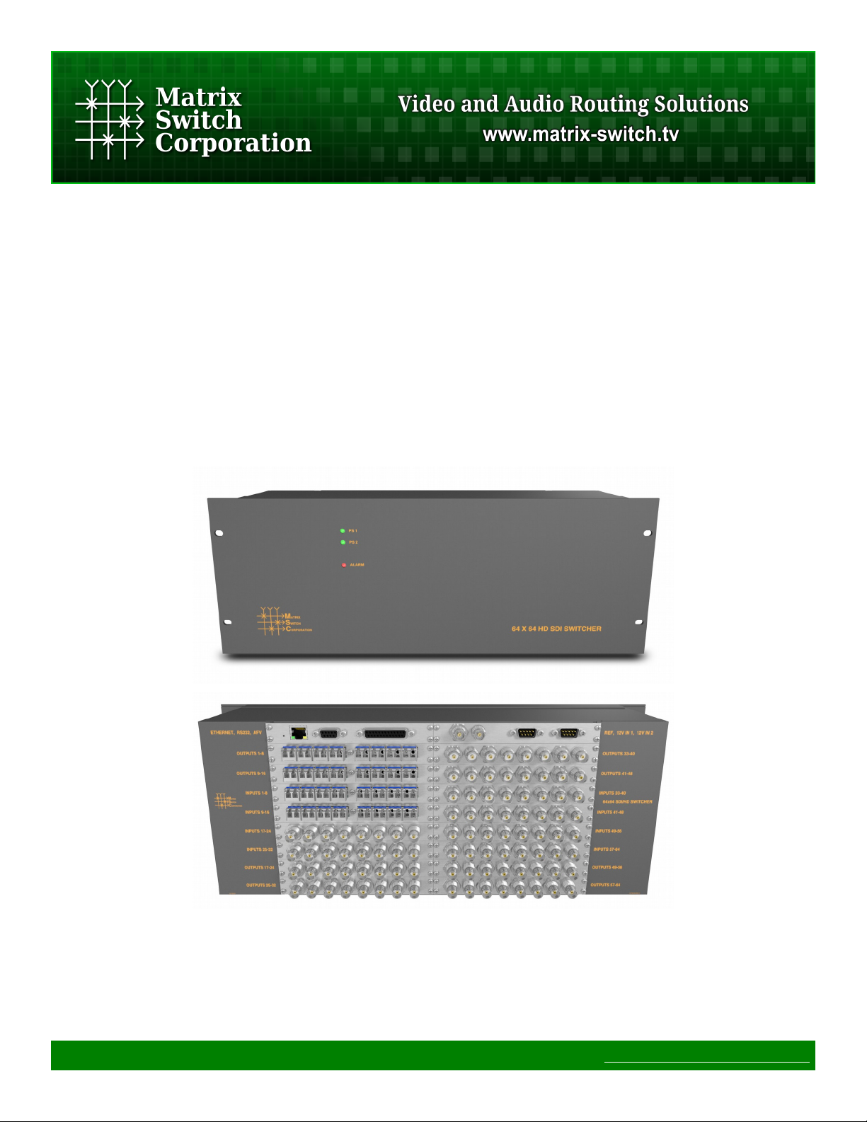
4RU 64 input 64 output 3G-SDI Modular Video Router
Revision 1.4
Page 1 of 64 © 2013-2016 Matrix Switch Corporation www.matrixswitchcorp.com

MSC-XDM4000 Product Manual
Legal Disclaimers
All material in this document is the legal property of Matrix Switch Corporation.
Information contained in this publication regarding device applications and the like is
provided for your convenience only and may be superseded by updates. It is your
responsibility to ensure that your application meets with your specications. MATRIX
SWITCH CORPORATION MAKES NO REPRESENTATIONS OR WARRANTIES OF ANY
KIND WHETHER EXPRESS OR IMPLIED, WRITTEN OR ORAL, STATUTORY OR
OTHERWISE, RELATED TO THE INFORMATION, INCLUDING BUT NOT LIMITED TO
ITS CONDITION, QUALITY, PERFORMANCE, MERCHANTABILITY OR FITNESS FOR
PURPOSE. Matrix Switch Corporation disclaims all liability arising from this
information and its use. Use of Matrix Switch Corporation devices in life support and/or
safety applications is entirely at the buyer’s risk, and the buyer agrees to defend,
indemnify and hold harmless Matrix Switch Corporation from any and all damages,
claims, suits, or expenses resulting from such use. No licenses are conveyed, implicitly
or otherwise, under any Matrix Switch Corporation intellectual property rights.
Contacting Matrix Switch Corporation
Website
Toll Free
Phone
Email
http://www.matrixswitch corp.com
(800) 764-4084
+1 (530) 477-9122
Grass Valley, California
info@matrixswitch corp.com
Page 2 of 64 © 2013-2016 Matrix Switch Corporation www.matrixswitch corp.com

MSC-XDM4000 Product Manual
Table 1: Document Revision History
Revision & Date Changes
Revision 1.4
2016-08-01
Revision 1.3
2016-05-17
Revision 1.2
2015-08-20
Revision 1.1
2014-06-24
2014-03-17 • Fixed some document cross references.
2013-11-29 • MSC-4HDX6464 manual released.
• Mascot protocol updated to 3.0 with System Parameter commands,
Matrix I/O mapping commands, and Panel/GPIO commands.
• Improved Software Update documentation.
• Added pinouts for RS-232 and RS-485 serial port and GPIO
Auxiliary interface.
• Added XD series systems.
• Added MSC-CP59X59E panel.
• Added protocol commands: MtxGroup, PanelDis, and PanelExtEn.
• Updated Mascot protocol information to version 2.4.
• New manuals for MSC-V1616(LS)(+DC), MSC-1HD1616(LS)(+DC)
• Updated External Button Control Pinout section.
• Added External Button Control information for MSC-HD42L.
• Minor text content and gure position changes.
• Updated Mascot protocol information to version 2.3.
• Added Vars Mascot command description.
Revision 1.0
2013-04-15
Page 3 of 64 © 2013-2016 Matrix Switch Corporation www.matrixswitch corp.com
• Initial release of modular product manual.

MSC-XDM4000 Product Manual
Table of Contents
1 Getting Started....................................................................................................................................................7
1.1 Device Connections......................................................................................................................................7
1.2 Video I/O Boards...........................................................................................................................................8
1.2.1 Installing Video I/O Boards...................................................................................................................9
1.2.2 SFP Modules........................................................................................................................................10
1.3 Powering Up The Device............................................................................................................................11
1.4 Front Status Panel........................................................................................................................................11
1.5 Web Page Interface......................................................................................................................................12
1.5.1 Accessing The Web Page Interface......................................................................................................12
1.5.2 Network Settings.................................................................................................................................12
1.5.3 Matrix Routing....................................................................................................................................13
1.5.4 Labels..................................................................................................................................................13
1.5.5 Presets..................................................................................................................................................13
1.6 Network Planning........................................................................................................................................13
1.6.1 Installation Example............................................................................................................................15
2 Web page interface............................................................................................................................................16
2.1 Overview.....................................................................................................................................................16
2.2 Routing Tab.................................................................................................................................................16
2.2.1 Changing a connection........................................................................................................................17
2.2.2 Loading a preset..................................................................................................................................17
2.3 Presets Tab...................................................................................................................................................17
2.3.1 Loading Work Matrix from a source target.........................................................................................18
2.3.2 Saving Work Matrix to a target...........................................................................................................18
2.3.3 Usage scenarios...................................................................................................................................18
2.4 Labels Tab...................................................................................................................................................18
2.5 Config Tab...................................................................................................................................................19
2.5.1 System Settings...................................................................................................................................20
2.5.2 Network Settings.................................................................................................................................20
2.5.3 Button Panel Settings..........................................................................................................................21
2.6 Command Tab.............................................................................................................................................22
3 Mascot Control Protocol..................................................................................................................................23
3.1 Protocol Changes........................................................................................................................................23
3.2 Telnet Access...............................................................................................................................................24
3.3 Serial Access...............................................................................................................................................24
3.4 Command Format........................................................................................................................................24
3.4.1 Command Names................................................................................................................................25
3.5 Response Format.........................................................................................................................................25
3.6 Command Arguments..................................................................................................................................26
3.7 System Parameters......................................................................................................................................27
3.7.1 System Parameter Table......................................................................................................................28
3.8 Core Commands..........................................................................................................................................28
3.9 Configuration Commands...........................................................................................................................29
3.10 Miscellaneous Commands........................................................................................................................30
Page 4 of 64 © 2013-2016 Matrix Switch Corporation www.matrixswitch corp.com

MSC-XDM4000 Product Manual
3.10.1 C Command.......................................................................................................................................30
3.10.2 DestNames Command.......................................................................................................................30
3.10.3 DHCP Command...............................................................................................................................31
3.10.4 E Command.......................................................................................................................................31
3.10.5 Firmware Command..........................................................................................................................32
3.10.6 FrameIP Command............................................................................................................................32
3.10.7 Gateway Command...........................................................................................................................33
3.10.8 Get Command....................................................................................................................................33
3.10.9 GetS Command.................................................................................................................................34
3.10.10 Help Command................................................................................................................................34
3.10.11 IP Command....................................................................................................................................34
3.10.12 LockStatus Command.....................................................................................................................35
3.10.13 MAC Command..............................................................................................................................35
3.10.14 MapDest Command.........................................................................................................................35
3.10.15 MapSrc Command...........................................................................................................................36
3.10.16 MascotVer Command......................................................................................................................37
3.10.17 MtxCfg Command...........................................................................................................................37
3.10.18 MtxGroup Command.......................................................................................................................39
3.10.19 NetMask Command.........................................................................................................................40
3.10.20 P Command.....................................................................................................................................40
3.10.21 PAdd Command...............................................................................................................................41
3.10.22 PairIO Command.............................................................................................................................41
3.10.23 PanelCmd Command.......................................................................................................................42
3.10.24 PanelCmdEn Command..................................................................................................................43
3.10.25 PanelCond Command......................................................................................................................43
3.10.26 PanelDis Command.........................................................................................................................44
3.10.27 PanelExtEn Command.....................................................................................................................44
3.10.28 PanelRate Command.......................................................................................................................45
3.10.29 PClr Command................................................................................................................................45
3.10.30 ProtoSer Command.........................................................................................................................46
3.10.31 PsetNames Command......................................................................................................................46
3.10.32 PSub Command...............................................................................................................................47
3.10.33 PView Command.............................................................................................................................47
3.10.34 Reboot Command............................................................................................................................48
3.10.35 ReclkDis Command.........................................................................................................................48
3.10.36 RemoteSync Command...................................................................................................................48
3.10.37 S Command.....................................................................................................................................49
3.10.38 SerBaud Command..........................................................................................................................49
3.10.39 Set Command..................................................................................................................................50
3.10.40 SetA Command................................................................................................................................50
3.10.41 SetS Command................................................................................................................................51
3.10.42 SrcNames Command.......................................................................................................................51
3.10.43 SysName Command........................................................................................................................52
3.10.44 SysType Command..........................................................................................................................52
3.10.45 Vars Command................................................................................................................................53
3.10.46 W Command....................................................................................................................................54
Page 5 of 64 © 2013-2016 Matrix Switch Corporation www.matrixswitch corp.com

MSC-XDM4000 Product Manual
3.10.47 WebPass Command.........................................................................................................................54
3.10.48 X Command.....................................................................................................................................54
4 Software Updates..............................................................................................................................................56
4.1 Software Update on Pyxis Series Devices..................................................................................................56
4.2 Software failsafe recovery procedure..........................................................................................................56
4.3 TFTP Software............................................................................................................................................57
4.3.1 Windows..............................................................................................................................................57
4.3.2 Mac OS X............................................................................................................................................58
4.3.3 Linux....................................................................................................................................................58
5 Troubleshooting.................................................................................................................................................60
5.1 Unknown IP address....................................................................................................................................60
5.2 Unexpected reboots.....................................................................................................................................60
6 Reference...........................................................................................................................................................61
6.1 Specifications..............................................................................................................................................61
6.2 Serial Interface Pinout.................................................................................................................................61
6.3 GPIO Auxiliary Interface............................................................................................................................62
6.4 Glossary.......................................................................................................................................................63
7 Matrix Switch Corporation Warranty............................................................................................................64
Page 6 of 64 © 2013-2016 Matrix Switch Corporation www.matrixswitch corp.com

MSC-XDM4000 Product Manual
1 Getting Started
Congratulations on your purchase of a quality Matrix Switch Corporation product. This section contains a
general overview of device functionality and provides information to get you up and running quickly.
Additional sections in this manual can be consulted for more detailed information on the subsystems and
features of this product.
1.1 Device Connections
The MSC-XDM4000 comes with a power supply adapter, a redundant power supply and a documentation CD.
Additional cables and hardware are not usually provided.
• Power supply adapter – A 12 Volt 10 Amp power supply adapter is provided which is connected to the
DE-9 male connector on the device and plugged into a 100-240V 50/60Hz AC power source.
• Redundant power supply (Optional) – The additional redundant power supply can be connected via
the second power supply connector, to provide an additional power source in the event that one of the
supplies fails or is disconnected from the power source.
• Ethernet connector (Optional) – Connect to a network switch with an Ethernet cable. Required for
accessing the web page interface, TCP/IP Mascot interface or for interfacing with remote control panels.
This device can also be connected directly to a computer or remote panel (supports auto MDI-X
allowing a crossover or straight through Ethernet cable to be used).
• SDI BNC Video Inputs – Connect SDI sources to input connectors using 75 Ohm Coax cable with
BNC connectors designed for high speed SDI video applications. Unused inputs can be left
unconnected. Inputs with supported standard rate (3G, HD or SD) SDI signals will be auto re-clocked
for reduced jitter. Other non standard rates between 125 Mbit/s and 2.97 Gbit/s will be passed through
without re-clocking or jitter reduction. Adaptive cable equalization on each input can equalize input
signals from Belden type 1694A cables up to lengths of 120m (@3G), 140m (@HD) and 400m (@SD).
• SDI BNC Video Outputs – Connect SDI destinations to output connectors using 75 Ohm Coax cable
with BNC connectors designed for high speed SDI video applications. Unused outputs can be left
unconnected. Outputs utilize standard SMPTE levels of 800mV peak-to-peak.
• SDI SFP Video Inputs – SFP input cards provide the means to utilize industry standard MSA SFP
modules for flexibility down to a single input. We offer fiber optic and HDMI input SFP modules and
many 3rd party modules may also be used. See SFP Modules for more details.
• SDI SFP Video Outputs – SFP output cards provide the means to utilize industry standard MSA SFP
modules for flexibility down to a single output. We offer fiber optic and HDMI output SFP modules and
many 3rd party modules may also be used. See SFP Modules for more details.
• Composite Video – Connect composite video sources to input connectors and destinations to output
connectors using 75 Ohm Coax cable with BNC connectors. Unused inputs or outputs can be left
unconnected.
• External Audio Router (Optional) – An additional Matrix Switch Corporation AES or analog audio
router can be utilized with this router by connecting it to the AUX/GPIO connector with a 25 pin straight
through cable, adding an additional audio level independent of SDI embedded audio. NOTE: The audio
router should be powered on before the video router to ensure proper initial routing state or alternatively
Preset 0 can be recalled to initialize it at any time.
• Sync Reference (Optional) – If switching on vertical sync pulse is desired, connect one of the Sync
Reference connectors to a sync pulse signal (NTSC, PAL or tri-level) using 75 Ohm Coax with BNC
Page 7 of 64 © 2013-2016 Matrix Switch Corporation www.matrixswitch corp.com
MSC-XDM4000 Product Manual
connectors and the other Sync Reference connector can be used as a pass-through to additional properly
75 Ohm terminated equipment or a 75 Ohm terminator should be installed. If the sync reference
functionality is not used, both connectors can be left unconnected.
• RS-232 Serial (Optional) – If serial control is desired, using the Mascot P rotocol, connect a D9 female
to male straight through cable to a control system, such as a computer. Use 115200 bps 8N1 as the serial
configuration and enable local echo to see typed characters. See Serial Interface Pinout for additional
details.
• RS-485 Serial (Optional) – An RS-485 port is also available utilizing pins on the same D9 connector as
the RS-232 interface. This port is configured as a Mascot P rotocol control interface by default, but can
also be used to control other routers as additional matrix levels. See Serial Interface Pinout for
additional details.
• General Purpose I/O – A D25 connector provides a GPIO auxiliary port with up to 24 input or output
3.3V logic lines for control and status interfacing with external equipment (LEDs, buttons, etc). See
GPIO Auxiliary Interface for more details.
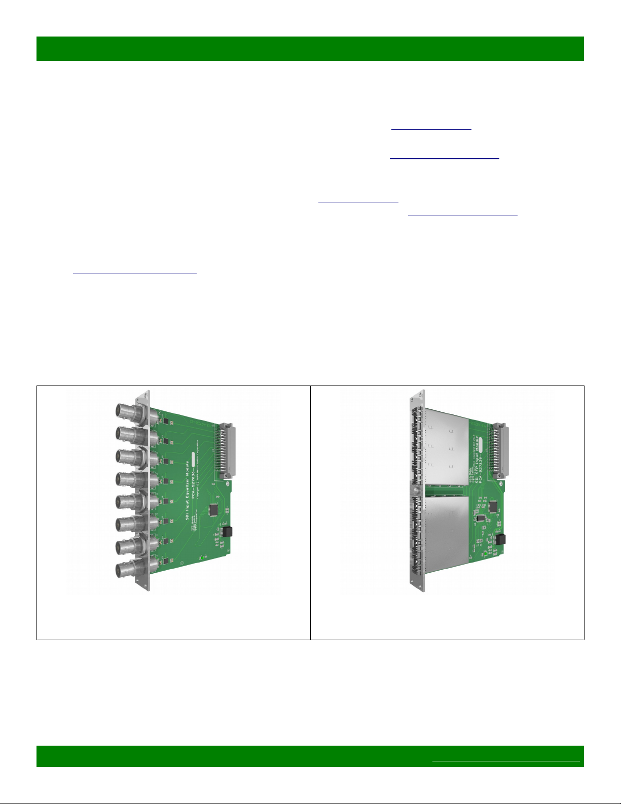
1.2 Video I/O Boards
The MSC-XDM4000 modular router can be configured or expanded in the field for matrix sizes in increments
of 8 inputs or outputs. Each input card adds 8 SDI video BNC or SFP module inputs, depending on the card
(MSC-CARDRX-BNC8 as shown in Figure 1 or MSC-CARDRX-SFP8 in Figure 2 respectively). Each output
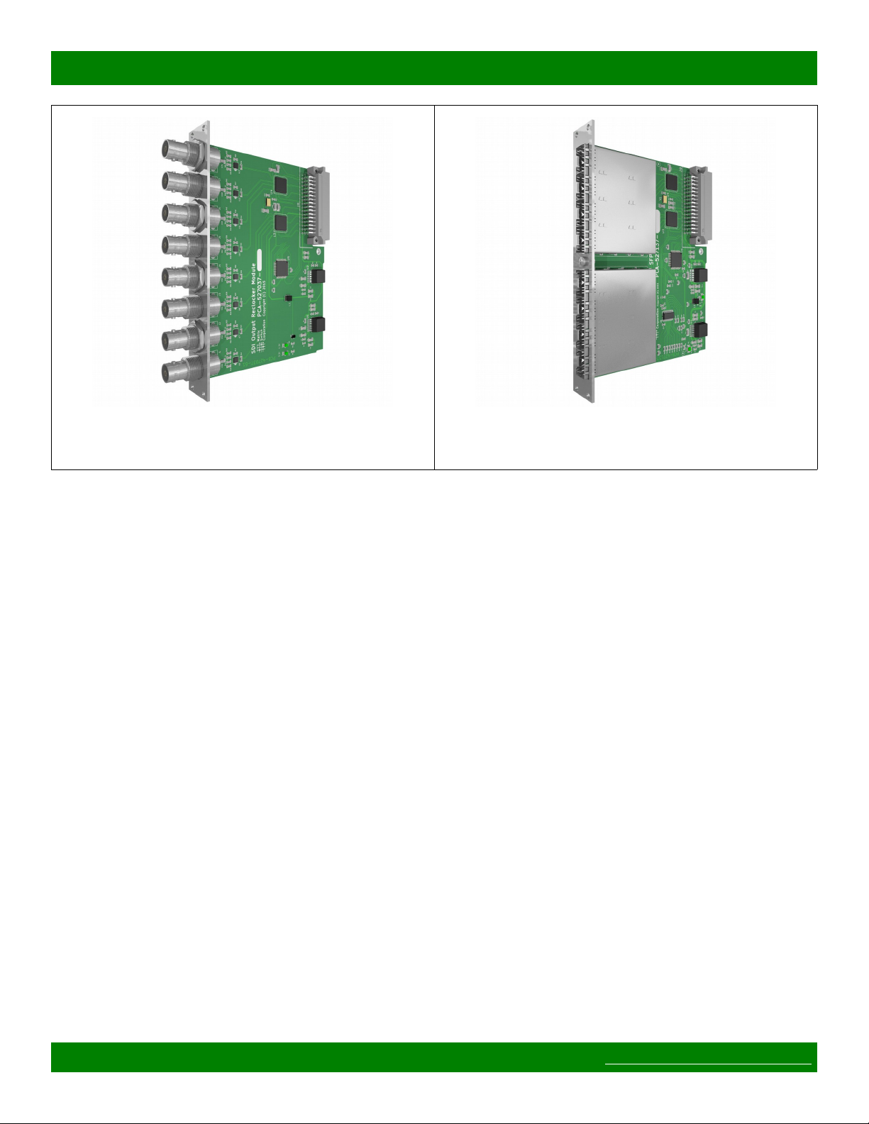
card adds 8 SDI video BNC or SFP module outputs (MSC-CARDTX-BNC8 as shown in Figure 3 or MSCCARDRX-SFP8 as shown in Figure 4).
Figure 1: MSC-CARDRX-BNC8 SDI BNC Input
Module
Page 8 of 64 © 2013-2016 Matrix Switch Corporation www.matrixswitch corp.com
Figure 2: MSC-CARDRX-SFP8 SDI SFP Input
Module
MSC-XDM4000 Product Manual
Figure 3: MSC-CARDTX-BNC8 SDI BNC Output
Module
Figure 4: MSC-CARDTX-SFP8 SDI SFP Output
Module
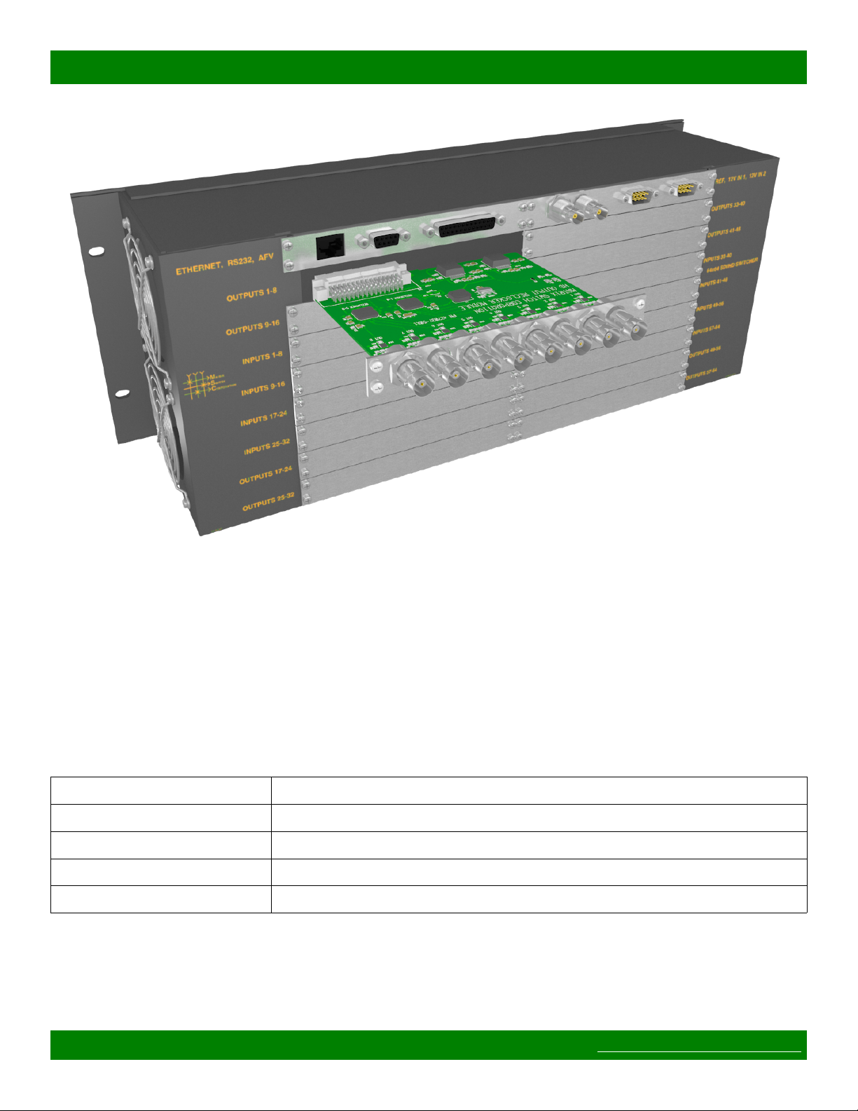
1.2.1 Installing Video I/O Boards
Once the I/O boards have been identified as either Input or Output modules, refer to the following installation
instructions.
Installation Instructions
1. Input and Output modules should be installed in sequential board slots beginning from the first slot
which will be labeled INPUTS 1-8 or OUTPUTS 1-8 respectively. Identify the board slots where the
boards will be installed and remove cover plates (if any), by removing the 4 mounting screws.
2. If the router is not currently mounted in a rack, installation may be easier with the router placed face
down on a table on something soft (to protect the front panel). If the router is already mounted,
installation can still be performed, but the I/O boards will need to be inserted horizontally, which makes
finding the card connector by feel slightly more difficult.
3. Ensuring the correct type of board is being used for a slot (Input or Output), position the board
connector first (opposite side of the BNC connectors) and board main component side towards the top of
the router, as depicted in Figure 5. Insert the card until it makes contact with the main crosspoint board
backplane. The card may need to be tilted up or down until it mates correctly with the main board
connector. It is important not to apply too much pressure when inserting the card, or damage may result
if the connector is not mating correctly. The board metal mounting plate should be flush against the
back of the router.
4. Once the I/O board is properly connected and the mounting plate is flush against the back of the router,
install the 4 mounting screws to hold it in place.
5. Repeat steps 3 and 4 for the remaining I/O boards.
Page 9 of 64 © 2013-2016 Matrix Switch Corporation www.matrixswitch corp.com
MSC-XDM4000 Product Manual
Figure 5: Video board installation example (MSC-XDM4000)
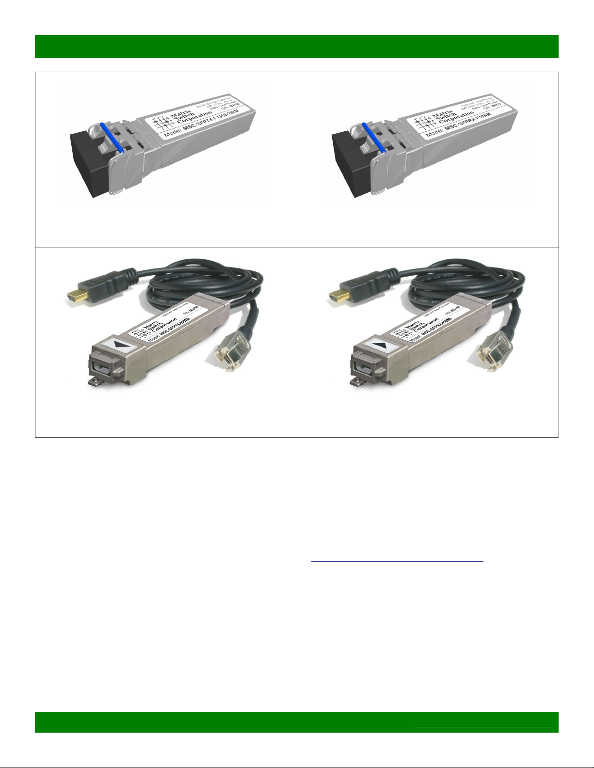
1.2.2 SFP Modules
The MSC-CARDRX-SFP8 and MSC-CARDTX-SFP8 modular I/O cards offer additional I/O flexibility down
to a single input or output using industry standard MSA compatible SFP modules. Matrix Switch Corporation
offers several SFP modules for fiber optic and HDMI signaling (see Table 2) and many 3rd party MSA
compatible modules can be used as well.
NOTE: MSA transceiver (transmit and receive) modules may be used with the MSC-XDM4000 but only the
transmit or receive side will be used (depending on the I/O card it is inserted into). To remain cost effective, it
is thus recommended that transmit only or receive only SFP modules are used when planning system I/O.
Model Description
MSC-SFPTX-F1310-10KM 3G-SDI SFP Video Transmitter, SMF 1310nm, 10km, LC connector
MSC-SFPRX-F10KM 3G-SDI SFP Video Receiver, SMF 1310nm, 10km, LC connector
MSC-SFPTX-HDMI HDMI Transmitter, HDMI D Connector
MSC-SFPRX-HDMI HDMI Receiver, HDMI D Connector
Table 2: Matrix Switch Corporation SFP Modules
Page 10 of 64 © 2013-2016 Matrix Switch Corporation www.matrixswitch corp.com
MSC-XDM4000 Product Manual
Figure 6: MSC-SFPTX-F1310-10KM SFP Fiber Optic
Transmitter
Figure 8: MSC-SFPTX-HDMI SFP HDMI Transmitter Figure 9: MSC-SFPRX-HDMI SFP HDMI Receiver
Figure 7: MSC-SFPRX-F10KM SFP Fiber Optic
Receiver
1.3 Powering Up The Device
This device is not equipped with a power switch and is simply connected to the power supply adapter which is
plugged into a suitable AC power source, to power it up.
Once the device is powered it goes through the following startup sequence:
• Reset switch is checked and if it is pressed then the Software failsafe recovery procedure is entered.
• Routing matrix is initialized to Preset 0 state (defaults to source 1 connected to all destinations).
1.4 Front Status Panel
The MSC-XDM4000 has a status front panel with 3 LED indicators, described in the following table:
Page 11 of 64 © 2013-2016 Matrix Switch Corporation www.matrixswitch corp.com

MSC-XDM4000 Product Manual
LED Label Description
PS 1 Power supply 1 good indicator.
PS 2 Power supply 2 good indicator.
FAULT Red LED for user configurable faults.
Table 3: Status Panel Indicators
This model is not equipped with a built-in button control panel, however several options are available for
controlling the device, including the web page interface, telnet, RS-232 serial and remote control panels.
1.5 Web Page Interface
All Matrix Switch Corporation router and panel devices come with a built-in web page interface.
This is the recommended interface for configuration and is also a convenient way to control the matrix routing
of the device.
Devices come factory configured with default settings, unless a pre-configuration request is made during
purchase, an example being a multi device application.
1.5.1 Accessing The Web Page Interface
The default network IP address for this device is 192.168.2.60. Refer to the table below for the default IP
addresses for other types of Matrix Switch Corporation devices.
Device Type Default IP Address
Video/Audio Routers 192.168.2.60
Remote Button Panels 192.168.2.64
Remote LCD Screen Panels 192.168.2.80
Table 4: Default System IP Addresses
To access the web page interface of the device:
1. Connect the Ethernet port of a computer either directly to the device using a straight through or
crossover cable to the same Ethernet network through a network switch or other LAN infrastructure.
2. Manually configure the computer's IP address to be a unique address on the same IP subnet as the
device. For example 192.168.2.10. The Netmask should be 255.255.255.0. A Gateway address is not
necessary for this purpose, but could be set to 192.168.2.1.
3. Make sure the device is powered on.
4. Using a web browser on the computer, enter the device's IP address into the Location bar and press
ENTER. The device web page interface should load. If the web page interface fails to load, double
check the computer's network settings and physical Ethernet connections. In the event that the IP
address of the device is unknown, refer to the Unknown IP Address troubleshooting section.
1.5.2 Network Settings
Network settings can be changed on the Config tab of the Web Page Interface. This includes DHCP enable, IP
Page 12 of 64 © 2013-2016 Matrix Switch Corporation www.matrixswitch corp.com

MSC-XDM4000 Product Manual
address, Netmask and Gateway settings. DHCP should only be used for assigning specific network settings
from a central DHCP server or when assigned IP addresses can be determined, otherwise configuring the device
via its IP address would be prevented if the IP address is unknown. After changing network settings, click the
Save button and then click the Reboot button to restart the device. Refer to the Config Tab - Network Settings
section for more details.
In the event that the device's IP address is unknown, refer to the Unknown IP Address troubleshooting section.
Refer to the Network Planning section for assistance with developing a network plan for multi-device
applications.
1.5.3 Matrix Routing
The Routing tab of the Web Page Interface provides a convenient way to view and change the matrix routing
state and is the default page shown.
A preset can also be recalled from this interface, by selecting one from the Load Preset drop down control.
Refer to the Routing Tab section for more details.
1.5.4 Labels
Labels can be assigned to video (and audio if applicable) sources and destinations. Labels can also be assigned
to presets. Labels can be up to 8 characters in length. The default source labels use “Src” as a prefix, and the
destination labels use “Dest” as a prefix (example: Src1). The presets are labeled “Startup” for Preset 0 and
“PresetN”, where N is a number from 1 to 9, for the remaining presets.
The Labels Tab on the Web Page Interface can be used for modifying labels. Click the Save button to store any
changes that are made. Refer the Labels Tab section for more details.
1.5.5 Presets
There are 10 stored matrix routing presets. Preset 0 is recalled on power up and by default routes source 1 to all
destinations. All other presets default to “No Change” for all destinations, which when recalled will have no
effect. Presets can assign a partial subset of destinations or all destinations as desired.
Presets can be modified on the Presets Tab of the Web Page Interface. Refer to the Presets Tab section for more
details.
1.6 Network Planning
The default device settings can be used without change in applications with a single router and optionally one
remote panel on the same Ethernet network. Larger installations or integration with existing IP LAN networks
require some network planning.
NOTE: Matrix Switch Corporation can assist in planning and pre-configuring devices for specific application
requirements at purchase time. Just ask a sales or customer service representative.
Manual IP address management is recommended, although a DHCP server can be a convenient option for
centrally managing IP addresses by device MAC address, the net effect still being a fixed IP for each device.
Consult your DHCP server documentation for information on assigning IP addresses by MAC address, if this
option is chosen.
All devices which need to communicate with one another (routers, remote panels and computers) need to be
Page 13 of 64 © 2013-2016 Matrix Switch Corporation www.matrixswitch corp.com

MSC-XDM4000 Product Manual
physically connected to the same LAN or allow IP packet routing between networks if on separate LANs.
SECURITY WARNING: Matrix Switch Corporation devices are meant for installation in trusted LAN
environments. In the event that remote device configuration or control is desired over public networks or the
Internet, it is strongly recommended that some form of inter-network security is utilized, such as firewalls and
encrypted VLAN or secure data tunnels. This is necessary to prevent undesired access to devices.
Devices on the same LAN need to be assigned unique IP addresses in the same IP subnet. Matrix Switch
Corporation devices are configured by default to use IP addresses in the class C IP subnet 192.168.2.x. When
integrating devices into an existing LAN network, unique IP addresses should be assigned from the applicable
network and the Netmask setting of the devices should be set to reflect the class (size) of the IP network (the
default of 255.255.255.0 is for class C, which accommodates up to 254 addresses).
The Gateway setting is required to be set to the IP address of the network gateway on remote panels which will
be accessing routers across network subnets, but this setting is otherwise not needed.
After assigning device network settings, including unique IP addresses, remote panels need to be assigned the
correct IP addresses to their Remote Router IP setting of the router they will control.
Additional configuration changes may be required, depending on the application and are described in
subsequent sections.
Page 14 of 64 © 2013-2016 Matrix Switch Corporation www.matrixswitch corp.com

MSC-XDM4000 Product Manual
1.6.1 Installation Example
The following diagram is of a simple installation example consisting of a 32x32 SDI Video Router, with a
secondary level 32x32 Analog Audio router connected via the AFV DB-25 interface, a 32x32 Remote Button
Panel, a 2RU LCD Remote Panel and a Computer system.
Page 15 of 64 © 2013-2016 Matrix Switch Corporation www.matrixswitch corp.com
2 Web page interface
2.1 Overview
MSC-XDM4000 Product Manual
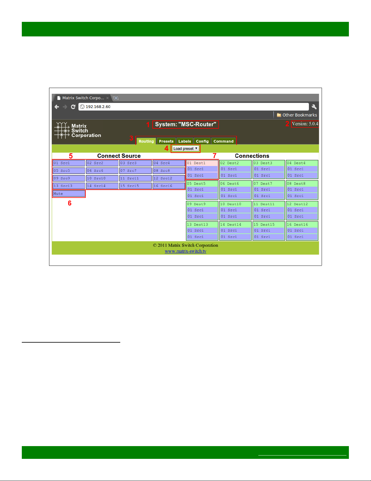
Figure 10: Routing Tab
All Matrix Switch Corporation Router and Remote Panel systems include a built in web page that can be used
with standards compliant Javascript enabled web browsers, including but not limited to Firefox, Chrome, Safari
and recent versions of Internet Explorer.
Figure 10 shows the Routing tab of a 16x16 switcher with 2 levels with numbered outlines to aid in further
description below. The web page interface for other router systems is sized appropriately. Remote Panels show
only the Config and Command tabs.
Numbered sections in Figure 10
1. System name (can be assigned on the Config tab)
2. System firmware series and version
3. Tab navigation
4. Preset load drop down selection
5. Source connect buttons
6. Mute button (may not be available on all switchers and levels)
7. Currently selected destination (destination name followed by currently connected source names for both
levels).
2.2 Routing Tab
Page 16 of 64 © 2013-2016 Matrix Switch Corporation www.matrixswitch corp.com
MSC-XDM4000 Product Manual
The right side of the Routing tab interface under the title “Connections” displays the current state of the routing
matrix. Each destination is depicted as a box containing the destination number/label followed by one or more
source numbers/labels of the currently connected sources for each level of the destination. The currently
selected destination is highlighted in red (#7 in Figure 10). For multi-level systems either the destination or one
of the levels can be individually selected for changing all levels or a single level.
The left side of the Routing tab under the title “Connect Source” (#5 in Figure 10) displays all the available
sources and Mute (if available) to connect from.
2.2.1 Changing a connection
To change a routing connection, select the desired destination by clicking on the Destination label or an
individual level source label (multi-level systems only). Then click on a Source button or Mute (if available)
from the “Connect Source” section. The clicked source will be connected to the selected Destination for one or
more levels (depending on if the Destination or a single level is selected).
2.2.2 Loading a preset
Presets store connection states for one or more Destinations. Loading a Preset on the Routing tab consists of
simply clicking on the “Load preset” drop down selector (#4 in Figure 10) and selecting the desired preset,
which is then loaded and applied to the current routing matrix. More information on Presets is contained in the
following Presets tab section.
2.3 Presets Tab
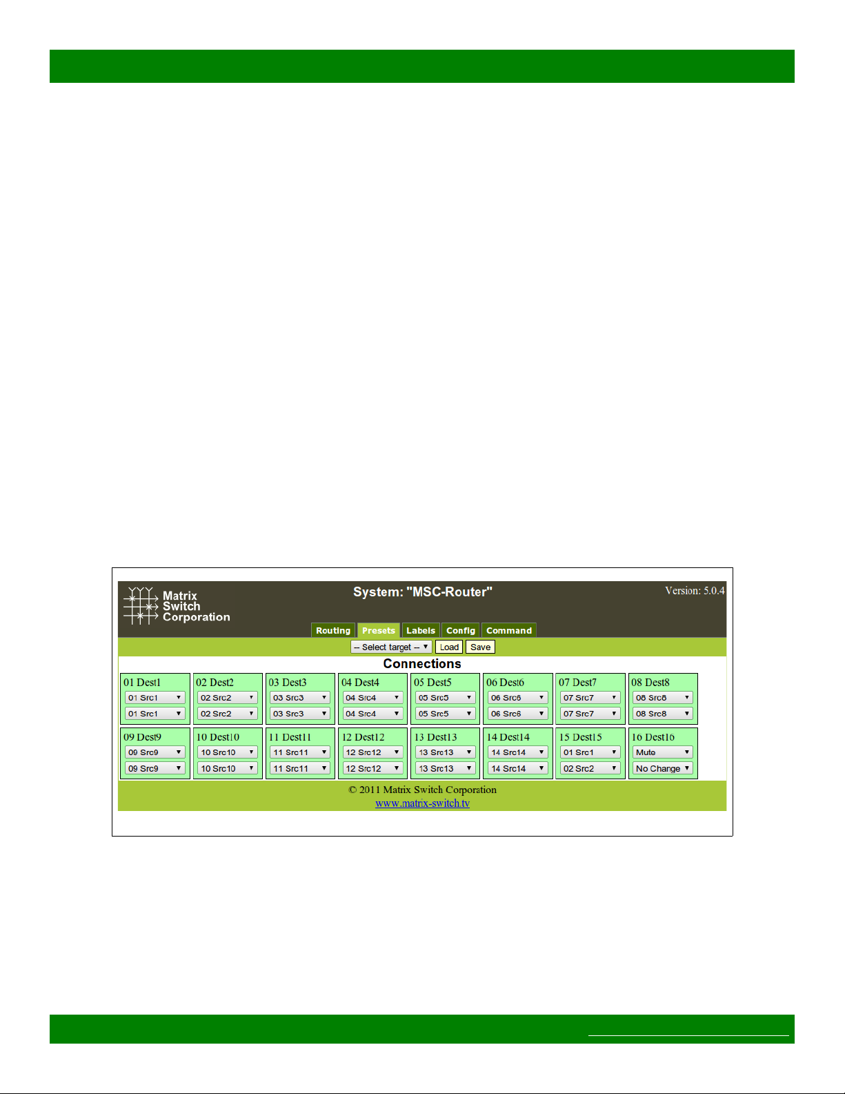
Figure 11: Presets Tab
Figure 11 depicts the Presets Tab which can be used to edit presets or perform batch matrix connection
operations. Under the “Connections” title is shown the Work Matrix, which is a temporary area for working
with matrix routing and loading to/saving from stored Presets and the current Active Routing state. For each
Destination the Destination number and label is displayed followed by one or more drop down selection lists for
each source level. The selection lists contain all available sources (listed by source number and label) and the
special values No Change and Mute (the latter only if available for the given level). The No Change option
indicates that the Destination for the given Level should not be changed from its current value, when the preset
Page 17 of 64 © 2013-2016 Matrix Switch Corporation www.matrixswitch corp.com

MSC-XDM4000 Product Manual
is recalled, which allows for a subset of the routing matrix to be changed. Mute will output blank Video or
silent Audio for the given Destination level and is not supported on all routers/levels.
2.3.1 Loading Work Matrix from a source target
The Work Matrix can be loaded from the current Active Routing matrix or a Preset. Simply select the desired
source target from the “Select target” drop down list and click the Load button.
2.3.2 Saving Work Matrix to a target
The Work Matrix can be saved to one or more targets including the Active Routing matrix or a Preset.
Simply select the desired destination target from the “Select target” drop down list and click the Save button.
When saving to the Active Routing matrix, the connections defined in the Work Matrix will become
immediately active for the current routing state, allowing for batch routing operations to be performed and
executed simultaneously. Saving to a Preset will store the Work Matrix state to non volatile memory, which
persists through device power cycles and can be recalled at a later time.
2.3.3 Usage scenarios
The flexibility of the Presets Tab interface allows for several useful scenarios, some of which are described
below:
• Batch connection operations – To perform several connection operations all at the same time: make the
desired connection changes to the Work Matrix, leaving all others as “No Change”, and then apply the
changes to the Active Routing target by selecting it from the “Select target” drop down and clicking the
Save button.
• Store Active Routing matrix state to a Preset – The entire Active Routing matrix state can be stored
to a Preset by first loading it to the Work Matrix, followed by selecting the desired target Preset and
clicking the Save button.
• Editing an existing Preset – Editing a Preset is done by loading it to the Work Matrix, making the
desired changes and saving it back to the same Preset. All this is accomplished without changing the
Active Routing matrix state.
2.4 Labels Tab
Page 18 of 64 © 2013-2016 Matrix Switch Corporation www.matrixswitch corp.com
MSC-XDM4000 Product Manual
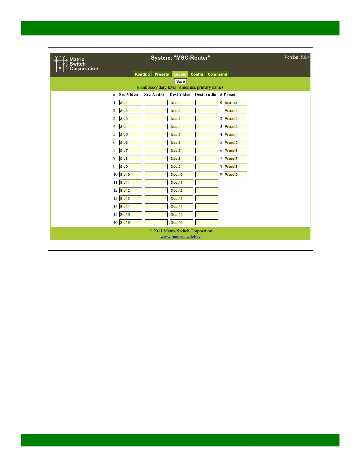
Figure 12: Labels Tab
Figure 12 shows the Labels Tab. Click on a field or use the tab key to step between fields. Label names are
limited to 8 characters including spaces. Multi-level routers will have columns for Video and Audio Sources
and Destinations. Single level routers will have a column for Source labels and one for Destination labels. On
multi-level routers, secondary levels can be left blank to use the same label as the first level. Presets can also be
assigned label names. Click the Save button to save changes that have been made.
2.5 Config Tab
Page 19 of 64 © 2013-2016 Matrix Switch Corporation www.matrixswitch corp.com
MSC-XDM4000 Product Manual
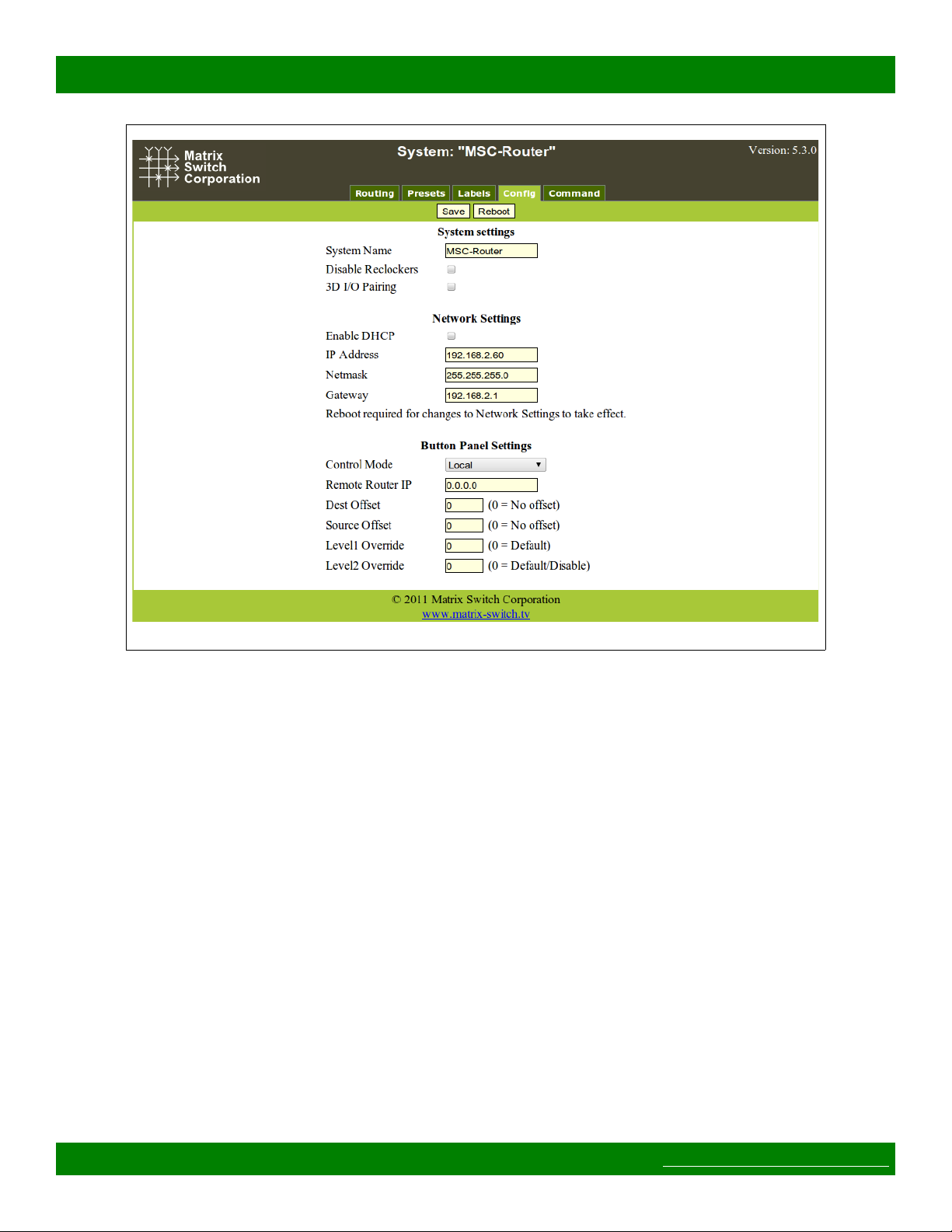
Figure 13: Config Tab
Figure 13 depicts the Config Tab as seen on a Router system beginning with Carina Series Firmware 5.3.0.
Configuration fields vary depending on router features, firmware version and if the device is a Remote Panel.
NOTE: After changing any configuration settings click the Save button. All Network Settings changes require
a Reboot of the device in order to take effect. After clicking Save, click the Reboot button to restart the device.
Remember to enter a new IP address into your Web browser's Location bar, if the device's IP address has
changed.
2.5.1 System Settings
• System Name – A descriptive name of the system (up to 15 characters), displayed at the top of the Web
Page interface which is helpful when managing multiple systems.
• Disable Reclockers – Disable SDI reclockers (not supported by all Routers, added with Carina Series
Firmware 5.3.0).
• 3D I/O Pairing – Enable pairing of destinations/sources for two channel 3D support (only supported by
Routers with 2 or more destinations, added with Carina Series Firmware 5.3.0).
2.5.2 Network Settings
WARNING: DHCP should only be enabled or the IP Address or Netmask changed if one has an
understanding of TCP/IP network configuration. Once the save button is pressed and the system is rebooted any
changes to DHCP enable, the IP Address or the Netmask shall result in having to access the web page with the
Page 20 of 64 © 2013-2016 Matrix Switch Corporation www.matrixswitch corp.com
 Loading...