

Matrix Switch Corporation MSC-GCP2U32 Product Manual
Matrix Switch Corporation
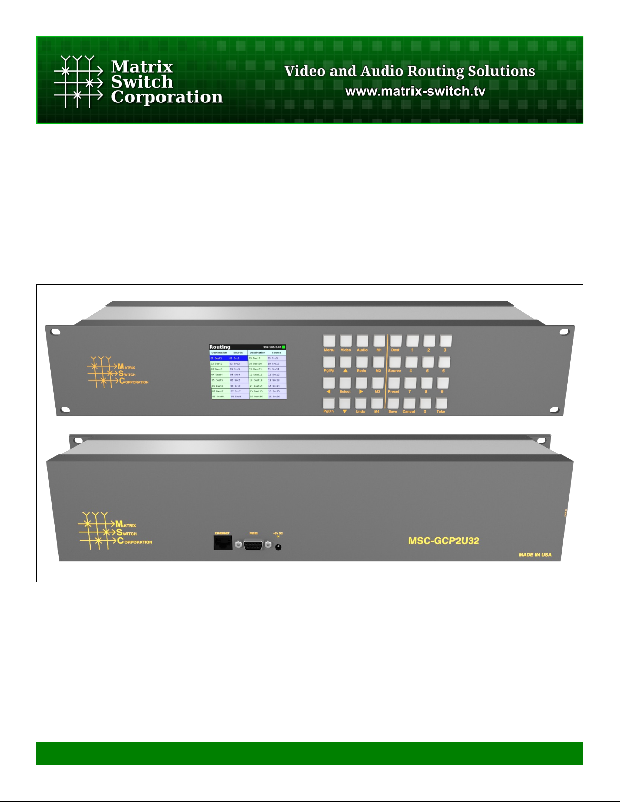
MSC-GCP2U32
Product Manual
2RU Remote Panel with LCD interface
Page 1 of 75 © 2013 Matrix Switch Corporation www.matrix-switch.tv

Legal Disclaimers
All material in this document is the legal property of Matrix Switch Corporation.
Information contained in this publication regarding device applications and the like is
provided for your convenience only and may be superseded by updates. It is your
responsibility to ensure that your application meets with your specifications. MATRIX
SWITCH CORPORATION MAKES NO REPRESENTATIONS OR WARRANTIES OF ANY KIND
WHETHER EXPRESS OR IMPLIED, WRITTEN OR ORAL, STATUTORY OR OTHERWISE,
RELATED TO THE INFORMATION, INCLUDING BUT NOT LIMITED TO ITS CONDITION,
QUALITY, PERFORMANCE, MERCHANTABILITY OR FITNESS FOR PURPOSE. Matrix Switch
Corporation disclaims all liability arising from this information and its use. Use of Matrix
Switch Corporation devices in life support and/or safety applications is entirely at the
buyer’s risk, and the buyer agrees to defend, indemnify and hold harmless Matrix Switch
Corporation from any and all damages, claims, suits, or expenses resulting from such
use. No licenses are conveyed, implicitly or otherwise, under any Matrix Switch
Corporation intellectual property rights.
Contacting Matrix Switch Corporation
Website http://www.matrix-switch.tv
Phone (530) 477-9122
Email info@matrix-switch.tv
Page 2 of 75 © 2013 Matrix Switch Corporation www.matrix-switch.tv

Publication History
Date Changes
2013-04-15
• Initial release of modular manual layout.
Page 3 of 75 © 2013 Matrix Switch Corporation www.matrix-switch.tv

Table of Contents
1 Getting Started....................................................................................................................................................8
1.1 Device Connections......................................................................................................................................8
1.2 Powering Up The Device..............................................................................................................................8
1.3 Front Panel LCD Interface............................................................................................................................9
1.4 Web Page Interface........................................................................................................................................9
1.4.1 Accessing The Web Page Interface.......................................................................................................9
1.4.2 Network Settings...................................................................................................................................9
1.4.3 Matrix Routing......................................................................................................................................9
1.4.4 Labels....................................................................................................................................................9
1.4.5 Presets....................................................................................................................................................9
1.4.6 Panel Remote Router IP Address..........................................................................................................9
1.5 Network Planning........................................................................................................................................10
1.5.1 Installation Example............................................................................................................................11
2 LCD User Interface...........................................................................................................................................12
2.1 Overview.....................................................................................................................................................13
2.1.1 Modes and Scopes...............................................................................................................................13
2.1.2 Buttons.................................................................................................................................................13
2.1.3 Navigation...........................................................................................................................................13
2.1.4 Status Bar.............................................................................................................................................13
2.2 Routing – Single Level................................................................................................................................13
2.2.1 Changing a Crosspoint........................................................................................................................13
2.3 Routing - Multi Level Audio/Video............................................................................................................13
2.3.1 Changing a Multi Level Crosspoint....................................................................................................13
2.4 Presets.........................................................................................................................................................13
2.4.1 Recalling a Preset................................................................................................................................13
2.4.2 Store a Preset.......................................................................................................................................13
2.5 Menu...........................................................................................................................................................13
2.6 Information..................................................................................................................................................13
2.7 Configuration..............................................................................................................................................13
2.7.1 General Config....................................................................................................................................13
2.7.2 Network Config...................................................................................................................................14
2.7.3 Matrix Profile......................................................................................................................................15
2.8 Reboot.........................................................................................................................................................16
3 Web page interface............................................................................................................................................17
3.1 Overview.....................................................................................................................................................17
3.2 Routing Tab.................................................................................................................................................18
3.2.1 Changing a connection........................................................................................................................18
3.2.2 Loading a preset..................................................................................................................................18
Page 4 of 75 © 2013 Matrix Switch Corporation www.matrix-switch.tv

3.3 Presets Tab...................................................................................................................................................18
3.3.1 Loading Work Matrix from a source target.........................................................................................19
3.3.2 Saving Work Matrix to a target...........................................................................................................19
3.3.3 Usage scenarios...................................................................................................................................19
3.4 Labels Tab...................................................................................................................................................19
3.5 Config Tab...................................................................................................................................................19
3.5.1 System Settings...................................................................................................................................19
3.5.2 Network Settings.................................................................................................................................20
3.5.3 Button Panel Settings..........................................................................................................................20
3.6 Command Tab.............................................................................................................................................21
4 Virtual Routing.................................................................................................................................................22
4.1 Simple Matrix Profiles................................................................................................................................22
4.2 Virtual Matrix Types...................................................................................................................................23
4.3 Virtual Matrix JSON Format.......................................................................................................................25
4.3.1 Map Strings.........................................................................................................................................26
4.4 Virtual Matrix Examples.............................................................................................................................26
5 Mascot Control Protocol..................................................................................................................................30
5.1 Protocol changes.........................................................................................................................................30
5.2 Telnet access................................................................................................................................................30
5.3 Serial access................................................................................................................................................30
5.4 Command format........................................................................................................................................30
5.4.1 Command names.................................................................................................................................30
5.4.2 Command arguments...........................................................................................................................30
5.5 Response format..........................................................................................................................................30
5.6 Command argument values.........................................................................................................................31
5.7 Error codes..................................................................................................................................................31
5.8 Basic command reference...........................................................................................................................31
5.9 Advanced command reference....................................................................................................................31
5.10 MSC-GCP2U32 Commands.....................................................................................................................31
5.11 B Command ..............................................................................................................................................31
5.12 C Command..............................................................................................................................................31
5.13 DefaultProfile Command..........................................................................................................................31
5.14 DestNames Command...............................................................................................................................31
5.15 DHCP Command.......................................................................................................................................31
5.16 DNSPri Command....................................................................................................................................31
5.17 DNSSec Command...................................................................................................................................31
5.18 E Command...............................................................................................................................................31
5.19 Firmware Command..................................................................................................................................31
5.20 FrameIP Command...................................................................................................................................31
5.21 Gateway Command...................................................................................................................................31
5.22 Help Command.........................................................................................................................................31
Page 5 of 75 © 2013 Matrix Switch Corporation www.matrix-switch.tv

5.23 IP Command..............................................................................................................................................31
5.24 LockStatus Command...............................................................................................................................31
5.25 MAC Command........................................................................................................................................31
5.26 Macros Command.....................................................................................................................................31
5.27 MascotVer Command................................................................................................................................32
5.28 MtxCfg Command....................................................................................................................................32
5.29 MtxProfiles Command..............................................................................................................................35
5.30 NetMask Command..................................................................................................................................35
5.31 P Command...............................................................................................................................................35
5.32 PAdd Command........................................................................................................................................35
5.33 PairIO Command......................................................................................................................................35
5.34 PanelOfs Command..................................................................................................................................35
5.35 PanelProfile Command.............................................................................................................................35
5.36 PanelRate Command.................................................................................................................................35
5.37 PClr Command..........................................................................................................................................35
5.38 Profile Command......................................................................................................................................35
5.39 PsetNames Command...............................................................................................................................35
5.40 PSub Command.........................................................................................................................................35
5.41 PView Command......................................................................................................................................35
5.42 Quit Command..........................................................................................................................................35
5.43 Reboot Command......................................................................................................................................35
5.44 ReclkDis Command..................................................................................................................................35
5.45 RemoteSync Command.............................................................................................................................35
5.46 S Command...............................................................................................................................................35
5.47 SerBaud Command...................................................................................................................................35
5.48 SerProto Command...................................................................................................................................35
5.49 SrcNames Command.................................................................................................................................35
5.50 StoreCnt Command...................................................................................................................................35
5.51 SysDescr Command..................................................................................................................................36
5.52 SysName Command..................................................................................................................................36
5.53 SysType Command...................................................................................................................................36
5.54 Vars Command..........................................................................................................................................36
5.55 W Command.............................................................................................................................................36
5.56 WebPass Command...................................................................................................................................36
5.57 X Command..............................................................................................................................................36
6 Software Updates..............................................................................................................................................38
6.1 Software Update on Lupus and Lynx Series Devices.................................................................................38
7 Troubleshooting.................................................................................................................................................39
7.1 Unknown IP address....................................................................................................................................39
7.2 Unexpected reboots.....................................................................................................................................39
7.3 Device fails to startup – Failsafe boot instructions.....................................................................................39
Page 6 of 75 © 2013 Matrix Switch Corporation www.matrix-switch.tv

8 Reference...........................................................................................................................................................40
8.1 Specifications..............................................................................................................................................40
8.2 Glossary.......................................................................................................................................................40
9 Matrix Switch Corporation Warranty............................................................................................................41
Page 7 of 75 © 2013 Matrix Switch Corporation www.matrix-switch.tv

1 Getting Started
Congratulations on your purchase of a quality Matrix Switch Corporation product. This section of the manual
provides a general overview of device functionality and information needed to get you up and running quickly.
Additional sections of this manual provide more details and references on the subsystems and features of this
device.
1.1 Device Connections
The MSC-GCP2U32 comes with a power supply adapter and a documentation CD. Additional cables and
hardware are not provided.
• Power supply adapter – A 5 Volt 2 Amp power supply adapter is provided which is connected to the
3.4mm OD 1.3mm ID barrel connector on the device and plugged into a 100-240V 50/60Hz AC power
source.
• Ethernet connector – Connect to a network switch with an Ethernet cable. Required for controlling a
remote router, accessing the web page interface and using the TCP/IP Mascot interface. A crossover
cable can also be utilized for connecting directly to a computer (for configuration purposes) or the router
to control.
• RS-232 Serial (Optional) – If serial control is desired, using the Mascot P rotocol , connect a D9 female
to female straight through cable to a control system, such as a computer. Use 115200 bps 8N1 as the
serial configuration and enable local echo to see typed characters.
1.2 Powering Up The Device
This device is not equipped with a power switch and is simply connected to the power supply adapter which is
plugged into a suitable AC power source, to power it up.
Once the device is powered it goes through the following startup sequence:
• u-boot bootloader starts up (accessible via serial port by pressing a key in a serial console when
prompted to), which can be used for system recovery and failsafe startup (refer to the Failsafe boot
instructions section for details).
• LCD panel is initialized and displays the Matrix Switch Corporation logo.
• LCD button interface is initialized and routing page is displayed.
• The panel will initialize the matrix profile assigned with the DefaultProfile Command and attempt to
connect to the router(s) it references. The M1-M4 buttons will flash until the matrix profile has been
refreshed (successfully connected to all router(s)). If the panel is the master of the routing state, then
preset 0 is recalled.
1.3 Front Panel LCD Interface
This panel is equipped with an LCD interface which can be used for many configuration, control and status
Page 8 of 75 © 2013 Matrix Switch Corporation www.matrix-switch.tv

display functions. Refer to the LCD User Interface section for detailed operating instructions.
1.4 Web Page Interface
All Matrix Switch Corporation router and panel devices come with a built-in web page interface.
NOTE: The MSC-GCP2U32 LCD panel acts as a router proxy and offers many of the same control interfaces
as a router. Refer to the Virtual Routing section for more details.
Devices come factory configured with default settings, unless a pre-configuration request is made during
purchase, an example being a multi device application.
1.4.1 Accessing The Web Page Interface
The default network IP address for this device is 192.168.2.80. Refer to the table below for the default IP
addresses for other types of Matrix Switch Corporation devices.
Device Type Default IP Address
Video/Audio Routers 192.168.2.60
Remote Button Panels 192.168.2.64
Remote LCD Screen Panels 192.168.2.80
To access the web page interface of the device:
1. Connect the Ethernet port of a computer either directly to the device using a crossover cable or to the
same Ethernet network through a network switch or other LAN infrastructure.
2. Manually configure the computer's IP address to be a unique address on the same IP subnet as the
device. For example 192.168.2.10. The Netmask should be 255.255.255.0. The Gateway doesn't
matter for this purpose, but could be set to 192.168.2.1.
3. Make sure the device is powered on.
4. Using a web browser on the computer, enter the device's IP address into the Location bar and press
ENTER. The web page interface should load. If the web page interface fails to load, double check the
computer's network settings and physical Ethernet connections. In the event that the IP address of the
device is unknown, refer to the Unknown IP Address troubleshooting section.
1.4.2 Network Settings
Network settings can be changed on the Config tab of the Web Page Interface. This includes DHCP enable, IP
address, Netmask and Gateway settings. DHCP should only be used for assigning specific network settings
from a central DHCP server or when assigned IP addresses can be determined, otherwise configuring the device
via its IP address would be prevented if the IP address is unknown. After changing network settings, click the
Save button and then click the Reboot button to restart the device. Refer to the Config Tab - Network Settings
section for more details.
Page 9 of 75 © 2013 Matrix Switch Corporation www.matrix-switch.tv

In the event that the device's IP address is unknown, refer to the Unknown IP Address troubleshooting section.
Refer to the Network Planning section for assistance with developing a network plan for multi-device
applications.
1.4.3 Matrix Routing
The Routing tab of the Web Page Interface provides a convenient way to view and change the matrix routing
state and is the default page shown.
A preset can also be recalled from this interface, by selecting one from the Load Preset drop down control.
Refer to the Routing Tab section for more details.
1.4.4 Labels
Labels can be assigned to video (and audio if applicable) sources and destinations. Labels can also be assigned
to presets. Labels can be up to 8 characters in length. The default source labels use “Src” as a prefix, and the
destination labels use “Dest” as a prefix (example: Src1). The presets are labeled “Startup” for Preset 0 and
“PresetN”, where N is a number from 1 to 9, for the remaining presets.
The Labels Tab on the Web Page Interface can be used for modifying labels. Click the Save button to store any
changes that are made. Refer the Labels Tab section for more details.
1.4.5 Presets
There are 10 stored matrix routing presets. Preset 0 is recalled on power up and by default routes source 1 to all
destinations. All other presets default to “No Change” for all destinations, which when recalled will have no
effect. Presets can assign a partial subset of destinations or all destinations as desired.
Presets can be modified on the Presets Tab of the Web Page Interface. Refer to the Presets Tab section for more
details.
1.4.6 Panel Remote Router IP Address
Remote panels control Matrix Switch Corporation video/audio routers with the TCP/IP protocol via the Ethernet
port.
NOTE: The MSC-GCP2U32 LCD panel offers advanced Virtual Routing capabilities and has the ability to
control multiple routers via profiles. Refer to the Virtual Routing section for more details.
The Remote Router IP setting on the Config Tab of the Web Page Interface defines the IP address of the
remote router which the panel interface will control. This defaults to 192.168.2.60 on remote panels, which is
the default IP address of Matrix Switch Corporation routers.
After changing the Remote Router IP setting click the Save button to store the changes, which take effect
immediately (a reboot is not required).
Refer to the Config Tab - Button Panel Settings section for more details on configuring the Remote Router IP
Page 10 of 75 © 2013 Matrix Switch Corporation www.matrix-switch.tv

Address.
Refer to the Network Planning section for more details on configuring devices in multi-device applications.
1.5 Network Planning
The default device settings can be used without change in applications with a single router and optionally one
remote panel on the same Ethernet network. Larger installations or integration with existing IP LAN networks
require some network planning.
NOTE: Matrix Switch Corporation can assist in planning and pre-configuring devices for specific application
requirements at purchase time. Just ask a sales or customer service representative.
Manual IP address management is recommended, although a DHCP server can be a convenient option for
centrally managing IP addresses by device MAC address, the net effect still being a fixed IP for each device.
Consult your DHCP server documentation for information on assigning IP addresses by MAC address, if this
option is chosen.
All devices which need to communicate with one another (routers, remote panels and computers) need to be
physically connected to the same LAN or allow IP packet routing between networks if on separate LANs.
SECURITY WARNING: Matrix Switch Corporation devices are meant for installation in trusted LAN
environments. In the event that remote device configuration or control is desired over public networks or the
Internet, it is strongly recommended that some form of inter-network security is utilized, such as firewalls and
encrypted VLAN or secure data tunnels. This is necessary to prevent undesired access to devices.
Devices on the same LAN need to be assigned unique IP addresses in the same IP subnet. Matrix Switch
Corporation devices are configured by default to use IP addresses in the class C IP subnet 192.168.2.x. When
integrating devices into an existing LAN network, unique IP addresses should be assigned from the applicable
network and the Netmask setting of the devices should be set to reflect the class (size) of the IP network (the
default of 255.255.255.0 is for class C, which accommodates up to 254 addresses).
The Gateway setting is required to be set to the IP address of the network gateway on remote panels which will
be accessing routers across network subnets, but this setting is otherwise not needed.
After assigning device network settings, including unique IP addresses, remote panels need to be assigned the
correct IP addresses to their Remote Router IP setting of the router they will control.
Additional configuration changes may be required, depending on the application and are described in
subsequent sections.
Page 11 of 75 © 2013 Matrix Switch Corporation www.matrix-switch.tv
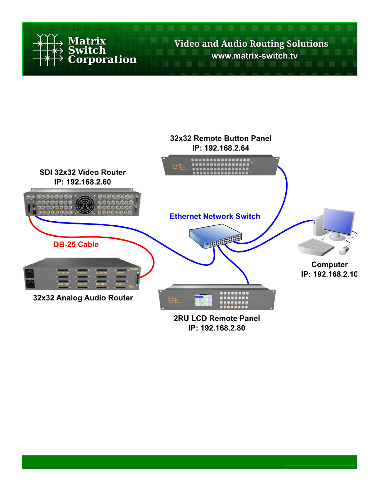
1.5.1 Installation Example
The following diagram is of a simple installation example consisting of a 32x32 SDI Video Router, with a
secondary level 32x32 Analog Audio router connected via the AFV DB-25 interface, a 32x32 Remote Button
Panel, a 2RU LCD Remote Panel and a Computer system.
Page 12 of 75 © 2013 Matrix Switch Corporation www.matrix-switch.tv
2 LCD User Interface
2.1 Overview
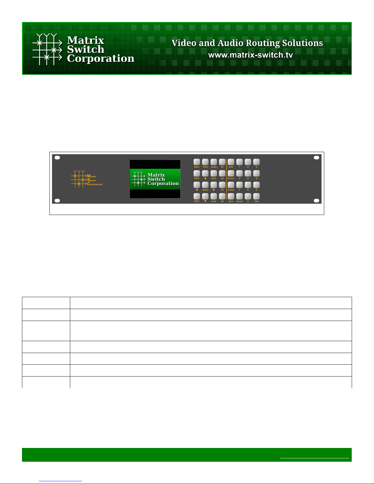
The MSC-GCP2U32 LCD control panel interface consists of a QVGA LCD screen and 32 buttons as depicted
in Figure 1.
Figure 1: MSC-GCP2U32 LCD Interface
2.1.1 Modes and Scopes
Operation of the LCD user interface depends on the current mode of the panel. Modes are activated by specific
buttons or by navigating and activating items listed on the display. Additionally Scopes describe overlapping
functionality that can be active simultaneously with the current Mode. Table 1 lists Modes and Scopes of the
LCD user interface.
Mode/Scope Description
Global Buttons in the Global scope are always available, regardless of the current panel Mode.
Navigation The Navigation scope is active when the Edit scope is not active and one or more selectable
items are displayed.
Edit The Edit scope is active when editing a configuration parameter.
Preset Preset mode is active when selecting a preset number to recall from or save to.
Destination Destination mode is active when selecting a destination for a crosspoint selection operation.
Source Source mode is active when selecting a source for a crosspoint selection operation.
Table 1: Modes and Scopes
2.1.2 Buttons
As seen in Table 2 the functionality of the user interface buttons depend on the current Mode and Scope of the
panel. Buttons are shown colored by functionality and scope in Figure 2 with the following key:
Page 13 of 75 © 2013 Matrix Switch Corporation www.matrix-switch.tv
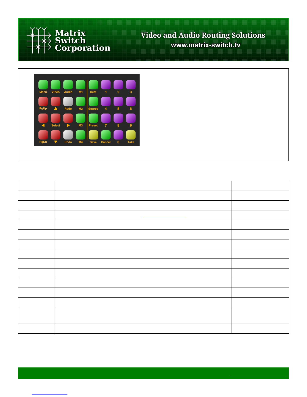
• ◼Green – Global buttons
• ◼Red – Navigation buttons
• ◼Purple – Number pad buttons
• ◼Yellow – Save and Take buttons
Figure 2: Interface Buttons
In subsequent button illustrations, the available buttons for the interface page being described are colored and
the non-applicable buttons are left as plain white.
Buttons Description Modes/Scopes
Menu Menu access button Global
Video/Audio Video and Audio toggle buttons Global
M1-M4 Macro buttons (refer to the Mascot Macros Command for details) Global
Dest Destination key-in mode activation Global
Source Source key-in mode activation Global
Preset Preset recall or store mode Global
Cancel Cancel operation Global
PgUp/PgDn Page Up and Page Down Navigation
Arrows Navigation arrows Navigation
Select Select or confirm an action Navigation
Save Data save Preset
Take Activate crosspoint routing change Preset, Dest, Source
0-9 Numbered buttons Navigation, Preset,
Dest, Source
Undo/Redo Undo and Redo (not currently used)
Table 2: Buttons
Page 14 of 75 © 2013 Matrix Switch Corporation www.matrix-switch.tv
2.1.3 Navigation
Most pages of the user interface consist of tabular information that
can be navigated (as shown in Figure 3). The currently selected
item is highlighted by a different background and foreground.
When multiple items are displayed, the Up and Down arrows can
be used to move the selection up or down by one item, PgUp and
PgDn can be used to move up or down by a complete page and
the Left and Right arrows can be used to select the item to the left
or right of the current selected item (equivalent to PgUp and
PgDn when there is only one column).
Items in the tabular information are identified by number, which is
the first number displayed at the beginning of the item's text. This
number can be keyed-in with the Number Pad (Buttons 0 through
9), for quick access. As digits are keyed-in, the active selection
will move to the next matching item with the given number, for example pressing 1 followed by 4 will select
entry 01 first followed by 14. The selection stops updating once the keyed in digits no longer match an
available item number. The key-in operation can be reset by pushing any of the navigation buttons.
Figure 3: Navigation and Status Bar
Once the desired item is selected, it can be activated by pressing the Select button, the effect of which depends
on the current interface page.
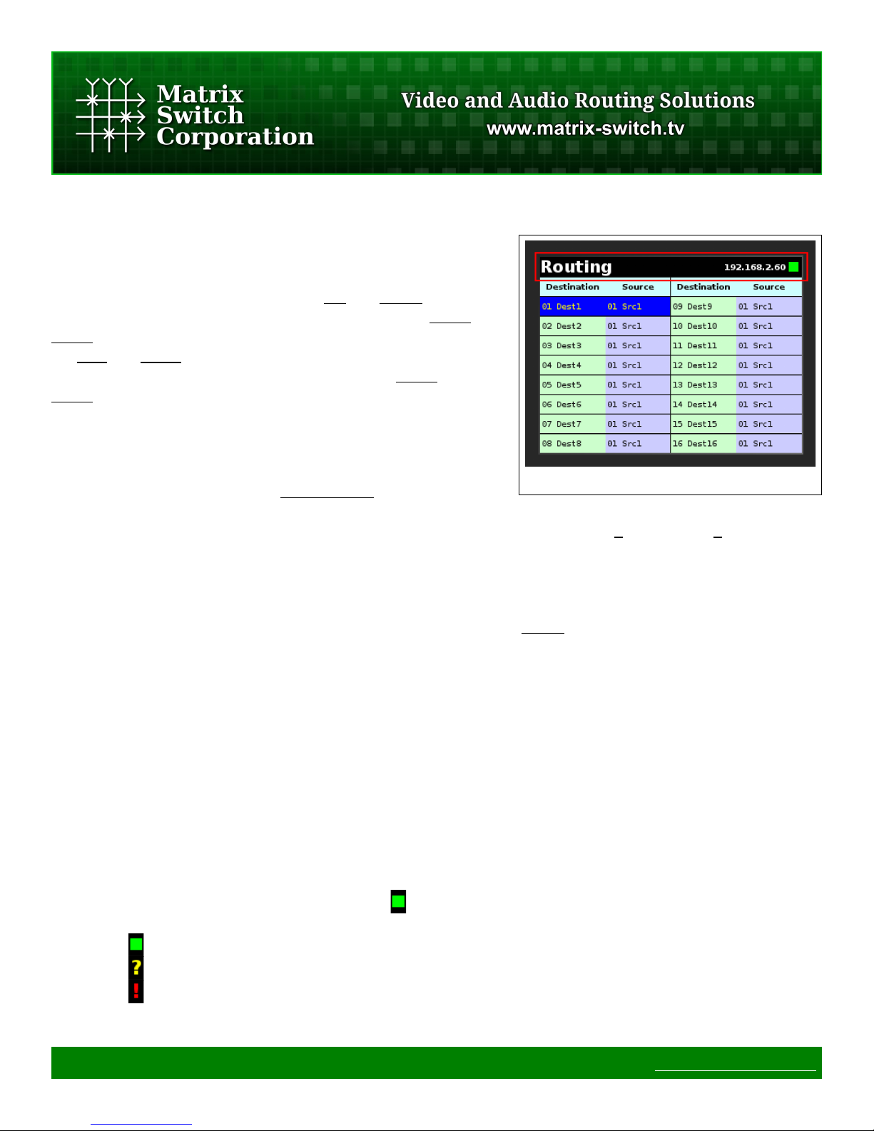
2.1.4 Status Bar
After the system starts up the status bar is displayed in all modes at the top of the screen (shown outlined in red
in Figure 3).
The status bar consists of:
• Mode Title (in the left corner – "Routing" in the example image). Indicates what section of the user
interface is currently active.
• Active Control Profile (to the right – "192.168.2.60" in the example image). Displays the name of the
current routing switcher control profile (useful when controlling multiple routers).
• Connection Status (in the right corner - " " in the example image). This indicator shows the current
routing switcher connection status, which includes the following indicators:
◦ - Indicates that a connection has been established with the remote routing switcher.
◦ - Displayed on initial connection when routing matrix state has not yet been updated.
◦ - Shown when a communication error occurs with the remote routing switcher.
Page 15 of 75 © 2013 Matrix Switch Corporation www.matrix-switch.tv
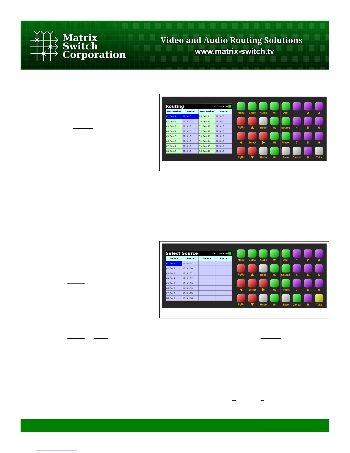
2.2 Routing – Single Level
The Routing page is the default interface page
and the active interface after device startup.
Note: pressing the Cancel button in most other
modes will return the interface to the Routing
page.
The current routing connection matrix state is
shown, as seen in Figure 4, one item per
destination, with the destination number and label followed by the connected source number and label. The
Navigation buttons can be used to change the currently selected item and to scroll through multiple pages if
applicable.
Figure 4: Routing
2.2.1 Changing a Crosspoint
There are 2 methods which can be used to change a matrix crosspoint connection called Navigation Method
and Key-In Method described below.
Navigation Method
1. Navigate to the desired destination item
using the Navigation buttons.
2. Press the Select button to activate
Source Mode.
3. The Select Source page is shown with
the currently connected source
highlighted (Figure 5).
4. Navigate to the source which is intended
to connect to the active destination.
5. Press the Select or Take buttons to complete the crosspoint connection or press Cancel to keep the
existing connection and return to the Routing page.
Figure 5: Routing Select Source
Key-In Method
1. Press the Dest button which will activate Destination Mode, buttons 0 through 9, Dest and Cancel will
flash awaiting further input (Destination Mode can be canceled by pressing the Cancel button or after 20
seconds of inactivity).
2. Key-in the desired destination of the crosspoint change using buttons 0 through 9 and the currently
selected destination will update accordingly on the display. To re-enter the destination number, press the
Page 16 of 75 © 2013 Matrix Switch Corporation www.matrix-switch.tv
Dest button again.
3. Press the Source button which will activate Source Mode, buttons 0 through 9, Source, Cancel and
Take will flash awaiting further input (Source Mode can be canceled by pressing the Cancel button or
after 20 seconds of inactivity).
4. Key-in the desired source of the crosspoint change using buttons 0 through 9 and the currently selected
source will update accordingly on the display. To re-enter the source number, press the Source button
again.
5. Press the Take button to complete the crosspoint connection or press Cancel to keep the existing
connection and return to the Routing page.
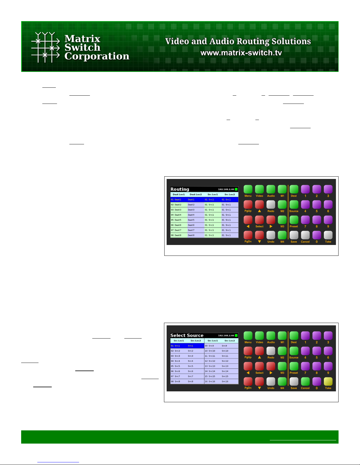
2.3 Routing - Multi Level Audio/Video
When controlling a routing switcher with
multiple levels, such as Video and Audio, the
Routing display is depicted as in Figure 6.
For each destination the destination labels and
the currently connected source numbers and
labels for both levels are shown.
Figure 6: Multi Level Routing
The Navigation buttons can be used to change
the currently selected item and to scroll through multiple pages if applicable.
2.3.1 Changing a Multi Level Crosspoint
There are 2 methods which can be used to change a matrix crosspoint connection called Navigation Method
and Key-In Method described below.
Both methods utilize the Audio and Video
buttons to toggle which levels of the crosspoint
will be modified by crosspoint changes. If the
Video button is toggled on, only the 1st level will
be changed. If the Audio button is toggled on,
only the 2nd level will be changed. If both Video
and Audio buttons are toggled off, then both
levels will be changed.
Navigation Method
Page 17 of 75 © 2013 Matrix Switch Corporation www.matrix-switch.tv
Figure 7: Routing Select Multi Level Source
1. Navigate to the desired destination item using the Navigation buttons.
2. Press the Select button to activate Source Mode.
3. The Select Source page is shown with the currently connected source highlighted (Figure 7 - shown
with both Video and Audio levels active).
4. Toggle on or off the Video and Audio buttons to the desired setting of the levels to be changed, if
necessary. The Select Source levels displayed will be updated accordingly.
5. Navigate to the source which is intended to connect to the active destination levels.
6. Press the Select or Take buttons to complete the crosspoint connection or press Cancel to keep the
existing connection and return to the Routing page.
Key-In Method
1. Press the Dest button which will activate Destination Mode, buttons 0 through 9, Dest and Cancel will
flash awaiting further input (Destination Mode can be canceled by pressing the Cancel button or after 20
seconds of inactivity).
2. Key-in the desired destination of the crosspoint change using buttons 0 through 9 and the currently
selected destination will update accordingly on the display. To re-enter the destination number, press the
Dest button again.
3. Press the Source button which will activate Source Mode, buttons 0 through 9, Source, Cancel and
Take will flash awaiting further input (Source Mode can be canceled by pressing the Cancel button or
after 20 seconds of inactivity).
4. Key-in the desired source of the crosspoint change using buttons 0 through 9 and the currently selected
source will update accordingly on the display. To re-enter the source number, press the Source button
again.
5. Toggle on or off the Video and Audio buttons to the desired setting of the levels to be changed, if
necessary. The Select Source levels displayed will be updated accordingly.
6. Press the Take button to complete the crosspoint connection or press Cancel to keep the existing
connection and return to the Routing page.
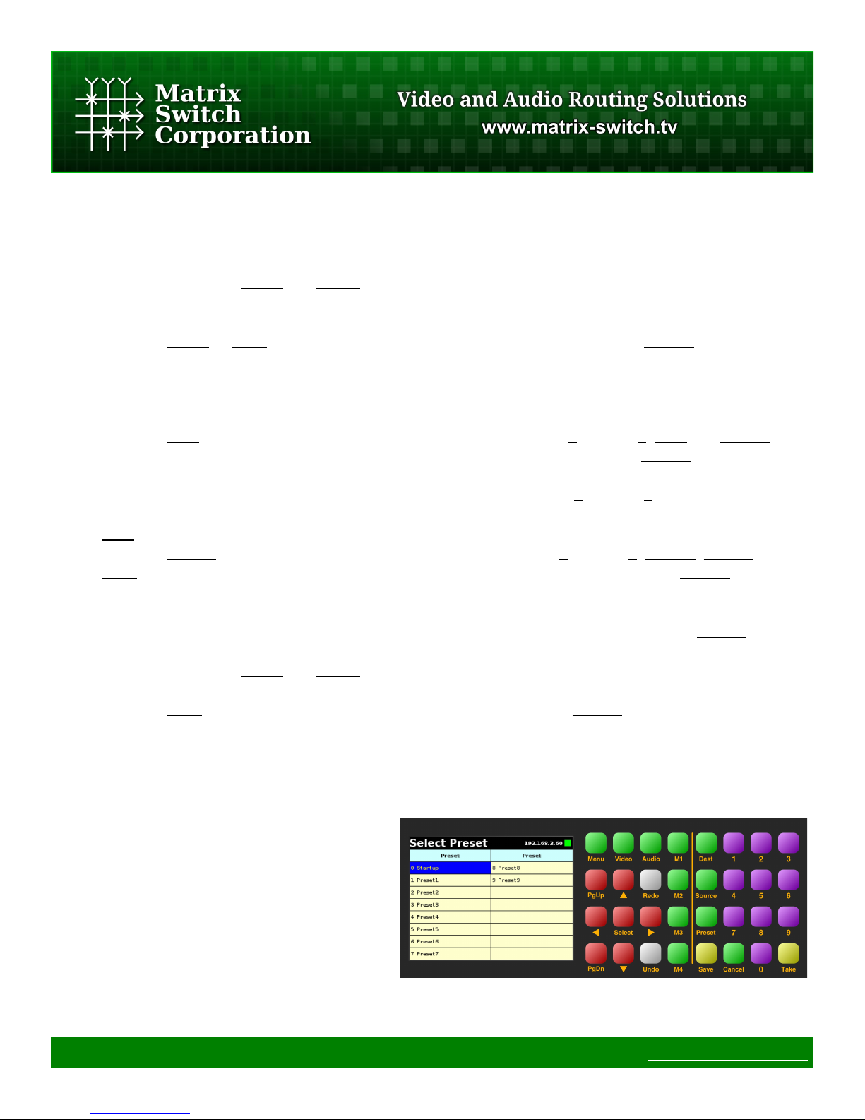
2.4 Presets
Matrix Switch Corporation routing switchers can
store up to 10 presets.
The MSC-GCP2U32 can recall a preset or store
the current entire routing matrix to a preset on
the router.
At this time, the MSC-GCP2U32 does not
support storing partial presets or building
Page 18 of 75 © 2013 Matrix Switch Corporation www.matrix-switch.tv
Figure 8: Presets
arbitrary presets not based on the current routing matrix using the LCD interface. However, the web page
interface or command protocol can be utilized for these purposes.
2.4.1 Recalling a Preset
Presets can be recalled using the following procedure:
1. Press the Preset button which will bring up the Select Preset page as seen in Figure 8. Pressing the
Cancel button or 20 seconds of inactivity will cancel Preset Mode and return to the Routing page.
2. Navigate to the desired preset using the Navigation buttons.
3. Press the Take or Select buttons to recall the preset to the current matrix routing state.
2.4.2 Store a Preset
The entire routing matrix state can be stored to a preset using the following procedure:
1. Press the Preset button which will bring up the Select Preset page as seen in Figure 8. Pressing the
Cancel button or 20 seconds of inactivity will cancel the Preset mode.
2. Navigate to the desired preset using the Navigation buttons.
3. Press the Save button to store the current matrix routing state to the selected preset.
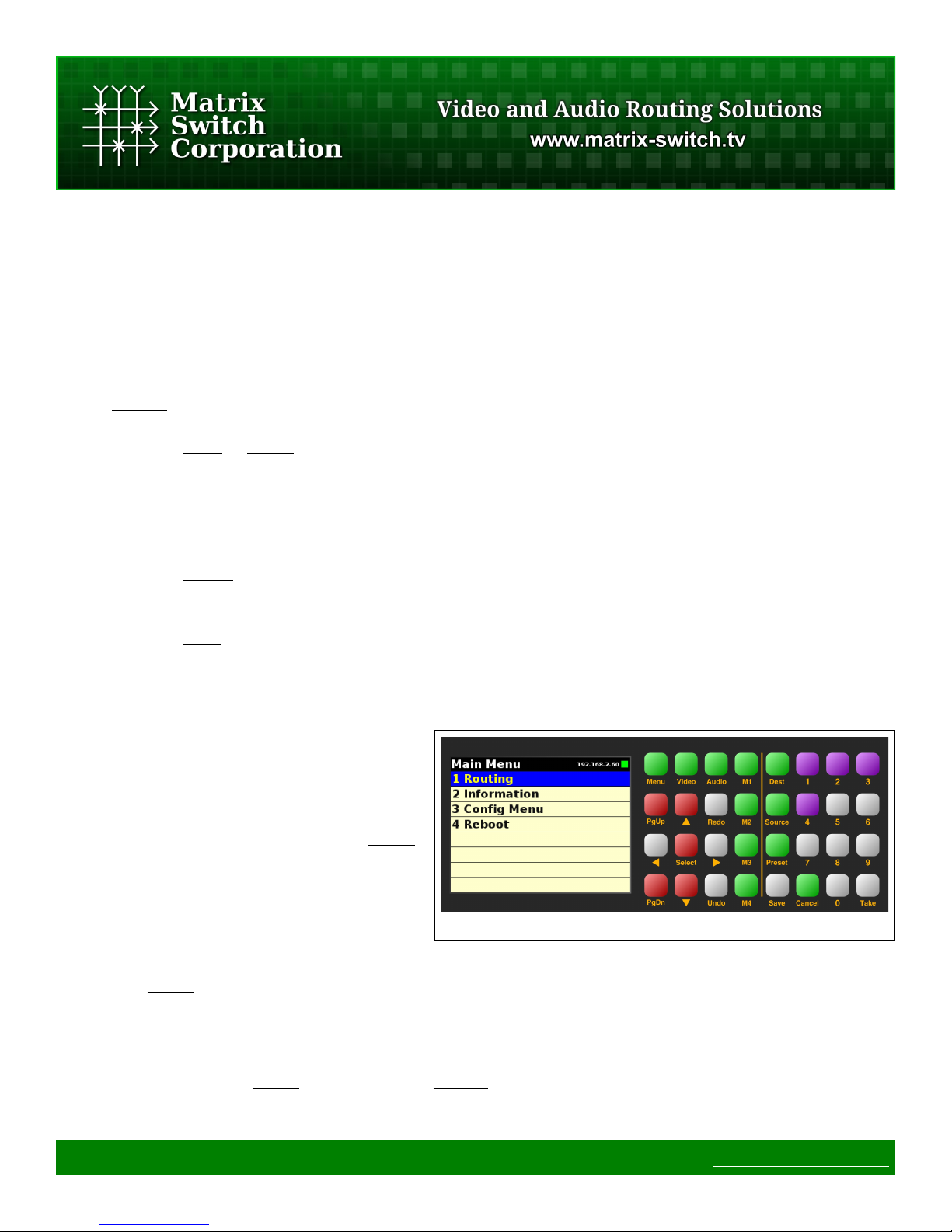
2.5 Menu
The menu pages are used for accessing other
areas of the MSC-GCP2U32, including device
information and configuration.
To access the menu at any time, press the Menu
button which will display the last used menu
page (Main Menu by default, as seen in Figure
9).
Figure 9: Main Menu
Navigation within menus is identical to other areas of the interface, including the Navigation buttons, Number
buttons and Select.
2.6 Information
The Information page is accessed from the Main Menu and shows the current Software Version. To return to
the Main Menu press the Menu button. Pressing Cancel will return to the Routing page.
Page 19 of 75 © 2013 Matrix Switch Corporation www.matrix-switch.tv
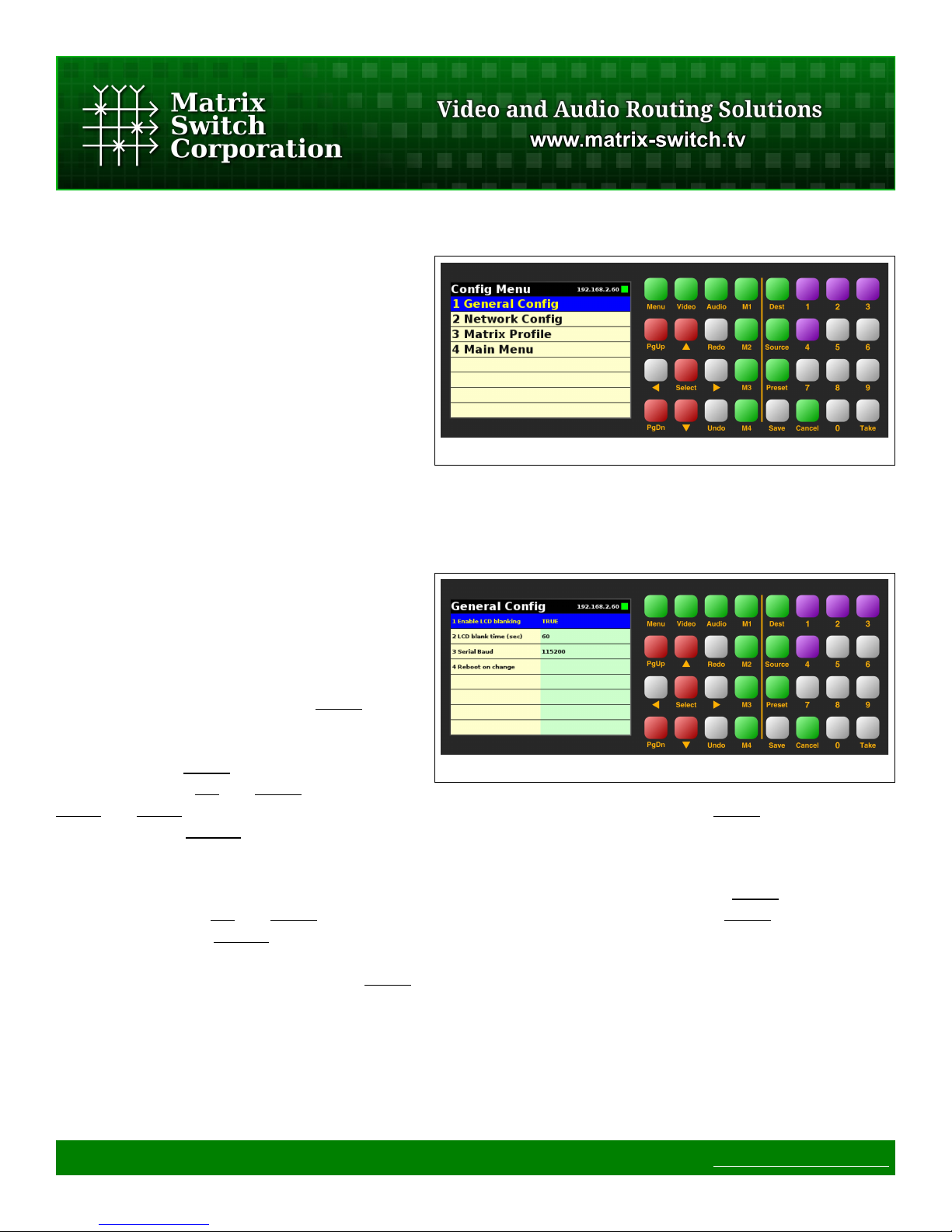
2.7 Configuration
Configuration of the MSC-GCP2U32 is
accessed with the Config Menu (Figure 10) and
several sub menus each of which is described
below.
2.7.1 General Config
General configuration consists of the following
options (as seen in Figure 11):
1. Enable LCD blanking
2. LCD blank time
3. Serial baud rate
The LCD Blanking feature causes the LCD
backlight to be turned off after a specified
number of seconds of button inactivity.
Figure 10: Config Menu
To enable or disable this option navigate to the
configuration option and press the Select button
to toggle the current value. To set the LCD
blanking time, navigate to the configuration
option, press the Select button to activate Edit
Mode and use the Up and Down arrows or
PgUp and PgDn to increase or decrease the value in seconds. To exit Edit Mode press Select again to save the
selected value or Cancel to keep the previous value.
The Serial Baud Rate can be changed by navigating to the configuration option, pressing Select to enter Edit
Mode and using the Up and Down arrows to change the value. To exit Edit Mode press Select again to save
the selected value or Cancel to keep the previous value. After changing the serial baud rate, the system needs
to be rebooted for the changes to take effect. The Reboot item on the General Config page can be used for this
purpose, by navigating to it, pressing the Select button and confirming the reboot dialog.
Figure 11: General Config
2.7.2 Network Config
The network configuration can be changed from this page as seen in Figure 12.
Page 20 of 75 © 2013 Matrix Switch Corporation www.matrix-switch.tv

Parameters include the following:
1. DHCP Enable
2. IP Address
3. Netmask
4. Gateway
5. Primary DNS
6. Secondary DNS
7. Router IP
Figure 12: Network Config
Note: After changing network parameters, the system needs to be restarted for the changes to take effect. The
"Reboot on change" can be used for this purpose by navigating to it, pressing the Select button and confirming
the Reboot dialog.
DHCP can be enabled or disabled by navigating to it and pressing the Select button to toggle the current state.
If enabled the remaining network settings (except Router IP) are not used and the network configuration will
be obtained from the network's DHCP server.
To set any of the remaining IP address settings, navigate to the parameter of interest and press the Select button
to enter Edit Mode. The first decimal number will be highlighted, awaiting input. Enter the desired value with
the Number buttons 0 through 9. The Right or Left arrows are used to select the next or previous IP address
decimal number. To exit Edit Mode press the Select or Save buttons to store the new value or Cancel to
discard the entered value and use the old one.
If DHCP is not enabled, the MSC-GCP2U32 will use the manual network configuration. This includes the
following settings: IP Address (192.168.2.80 by default), Netmask (255.255.255.0 by default) and Gateway
(192.168.2.1 by default). The Gateway address is only used when controlling routers outside of the current IP
subnet. The Primary and Secondary DNS entries are not currently needed and default to 0.0.0.0.
The Router IP setting allows for assigning the IP address of a single router to control. Setting up multiple
router control profiles currently requires using the web page or command protocol interfaces for configuration,
although the panel can be used to select between the available profiles.
2.7.3 Matrix Profile
The Matrix Profile page is accessed from the Config Menu and can be used to select the active router control
Page 21 of 75 © 2013 Matrix Switch Corporation www.matrix-switch.tv

profile.
Note: Configuring the available router control
profiles on the MSC-GCP2U32 currently
requires using the Mascot MtxProfiles
Command.
To select the current active router control profile
navigate to the Matrix Profile page from the
Config Menu. The names of the available
router control profiles will be listed as in Figure
Figure 13: Matrix Profile
13. Navigate to the desired profile and press
Select to activate it. The interface will return to the default Routing page and the new profile name will be
shown on the right side of the status bar.
The M1-M4 buttons are also configured by default to select one of the first 4 profiles. Refer to the Mascot
Macros Command for more details.
2.8 Reboot
The Reboot dialog (Figure 14) can be accessed
from the Main Menu, General Config and
Network Config pages.
The Left and Right arrows can be used to
navigate between the Reboot and Cancel
options. Pressing the Select button on the
Reboot option will reboot the system after a
short delay and the Cancel option will return the
Figure 14: Reboot
interface to the Routing page. The Cancel
button can also be utilized to cancel the reboot.
Page 22 of 75 © 2013 Matrix Switch Corporation www.matrix-switch.tv
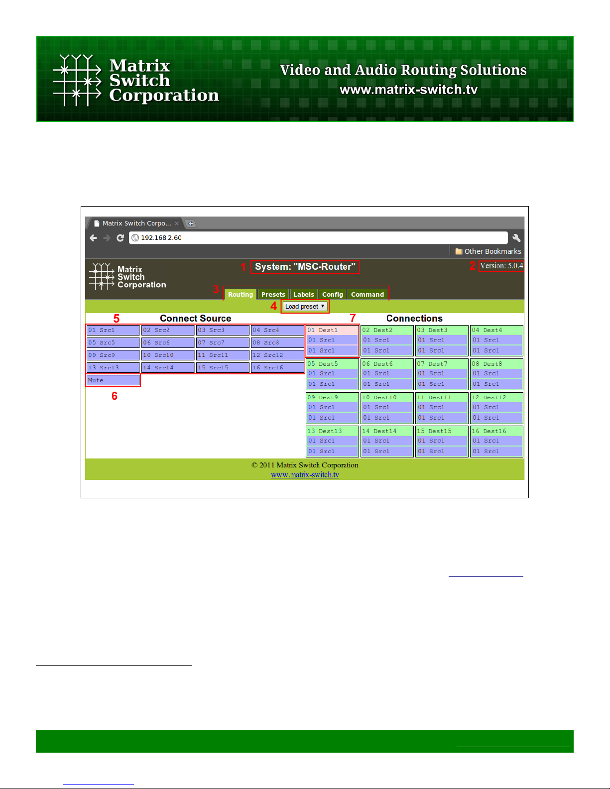
3 Web page interface
3.1 Overview
Figure 15: Routing Tab
All Matrix Switch Corporation Router and Remote Panel systems include a built in web page that can be used
with standards compliant Javascript enabled web browsers, including but not limited to Firefox, Chrome, Safari
and recent versions of Internet Explorer.
NOTE: The MSC-GCP2U32 LCD panel acts as a router proxy and offers many of the same control interfaces
as a router, including the Routing, Presets and Labels web interface tabs. Refer to the Virtual Routing section
for more details.
Figure 1 shows the Routing tab of a 16x16 switcher with 2 levels with numbered outlines to aid in further
description below. The web page interface for other router systems is sized appropriately. Remote Panels show
only the Config and Command tabs.
Numbered sections in Figure 1
1. System name (can be assigned on the Config tab)
2. System firmware version
3. Tab navigation
Page 23 of 75 © 2013 Matrix Switch Corporation www.matrix-switch.tv
 Loading...