

Page 1

Matrix Switch Corporation
MSC-CP16X16E
Product Manual
1RU 16x16 Remote Elastomeric Button Panel
Revision 1.5
Page 1 of 55 © 2013-2016 Matrix Switch Corporation www.matrixswitchcorp.com
Page 2

MSC-CP16X16E Product Manual
Legal Disclaimers
All material in this document is the legal property of Matrix Switch Corporation.
Information contained in this publication regarding device applications and the like is
provided for your convenience only and may be superseded by updates. It is your
responsibility to ensure that your application meets with your specications. MATRIX
SWITCH CORPORATION MAKES NO REPRESENTATIONS OR WARRANTIES OF ANY
KIND WHETHER EXPRESS OR IMPLIED, WRITTEN OR ORAL, STATUTORY OR
OTHERWISE, RELATED TO THE INFORMATION, INCLUDING BUT NOT LIMITED TO
ITS CONDITION, QUALITY, PERFORMANCE, MERCHANTABILITY OR FITNESS FOR
PURPOSE. Matrix Switch Corporation disclaims all liability arising from this
information and its use. Use of Matrix Switch Corporation devices in life support and/or
safety applications is entirely at the buyer’s risk, and the buyer agrees to defend,
indemnify and hold harmless Matrix Switch Corporation from any and all damages,
claims, suits, or expenses resulting from such use. No licenses are conveyed, implicitly
or otherwise, under any Matrix Switch Corporation intellectual property rights.
Contacting Matrix Switch Corporation
Website
Toll Free
Phone
Email
http://www.matrixswitch corp.com
(800) 764-4084
+1 (530) 477-9122
Grass Valley, California
info@matrixswitch corp.com
Page 2 of 55 © 2013-2016 Matrix Switch Corporation www.matrixswitch corp.com
Page 3

MSC-CP16X16E Product Manual
Table 1: Document Revision History
Revision & Date Changes
Revision 1.5
2016-11-18
Revision 1.4
2016-08-01
Revision 1.3
2016-05-17
Revision 1.2
2015-08-20
Revision 1.1
2014-06-24
2014-03-17 • Fixed some document cross references.
• Corrected External Button Control Pinout pin diagram for MSC-
HD41L, MSC-HD22L, and MSC-HD42L systems.
• Mascot protocol updated to 3.0 with System Parameter commands,
Matrix I/O mapping commands, and Panel/GPIO commands.
• Improved Software Update documentation.
• Added pinouts for RS-232 and RS-485 serial port and GPIO
Auxiliary interface.
• Added XD series systems.
• Added MSC-CP59X59E panel.
• Added protocol commands: MtxGroup, PanelDis, and PanelExtEn.
• Updated Mascot protocol information to version 2.4.
• New manuals for MSC-V1616(LS)(+DC), MSC-1HD1616(LS)(+DC)
• Updated External Button Control Pinout section.
• Added External Button Control information for MSC-HD42L.
• Minor text content and gure position changes.
2013-11-29 • MSC-4HDX6464 manual released.
• Updated Mascot protocol information to version 2.3.
• Added Vars Mascot command description.
Revision 1.0
2013-04-15
Page 3 of 55 © 2013-2016 Matrix Switch Corporation www.matrixswitch corp.com
• Initial release of modular product manual.
Page 4

MSC-CP16X16E Product Manual
Table of Contents
1 Getting Started....................................................................................................................................................7
1.1 Device Connections......................................................................................................................................7
1.2 Powering Up The Device..............................................................................................................................7
1.3 Front Panel Button Interface.........................................................................................................................7
1.3.1 Audio Breakaway..................................................................................................................................7
1.4 Web Page Interface........................................................................................................................................8
1.4.1 Accessing The Web Page Interface........................................................................................................8
1.4.2 Network Settings...................................................................................................................................8
1.4.3 Panel Remote Router IP Address...........................................................................................................9
1.5 Network Planning..........................................................................................................................................9
1.5.1 Installation Example............................................................................................................................10
1.6 Advanced Panel Configuration...................................................................................................................10
2 Web page interface............................................................................................................................................11
2.1 Overview.....................................................................................................................................................11
2.2 Config Tab...................................................................................................................................................11
2.2.1 System Settings...................................................................................................................................12
2.2.2 Network Settings.................................................................................................................................12
2.2.3 Button Panel Settings..........................................................................................................................13
2.3 Command Tab.............................................................................................................................................13
3 Mascot Control Protocol..................................................................................................................................15
3.1 Protocol Changes........................................................................................................................................15
3.2 Telnet Access...............................................................................................................................................16
3.3 Command Format........................................................................................................................................16
3.3.1 Command Names................................................................................................................................17
3.4 Response Format.........................................................................................................................................17
3.5 Command Arguments..................................................................................................................................17
3.6 System Parameters......................................................................................................................................18
3.6.1 System Parameter Table......................................................................................................................19
3.7 Core Commands..........................................................................................................................................20
3.8 Configuration Commands...........................................................................................................................20
3.9 Miscellaneous Commands..........................................................................................................................21
3.10 Command Reference.................................................................................................................................21
3.10.1 B Command.......................................................................................................................................22
3.10.2 C Command.......................................................................................................................................22
3.10.3 DestNames Command.......................................................................................................................22
3.10.4 DHCP Command...............................................................................................................................23
3.10.5 E Command.......................................................................................................................................23
3.10.6 Firmware Command..........................................................................................................................24
3.10.7 FrameIP Command............................................................................................................................24
3.10.8 Gateway Command...........................................................................................................................24
3.10.9 Get Command....................................................................................................................................25
3.10.10 GetS Command...............................................................................................................................26
3.10.11 Help Command................................................................................................................................26
Page 4 of 55 © 2013-2016 Matrix Switch Corporation www.matrixswitch corp.com
Page 5

MSC-CP16X16E Product Manual
3.10.12 IP Command....................................................................................................................................26
3.10.13 LockStatus Command.....................................................................................................................26
3.10.14 MAC Command..............................................................................................................................27
3.10.15 MapDest Command.........................................................................................................................27
3.10.16 MapSrc Command...........................................................................................................................28
3.10.17 MascotVer Command......................................................................................................................29
3.10.18 MtxCfg Command...........................................................................................................................29
3.10.19 MtxGroup Command.......................................................................................................................31
3.10.20 NetMask Command.........................................................................................................................32
3.10.21 P Command.....................................................................................................................................32
3.10.22 PAdd Command...............................................................................................................................33
3.10.23 PairIO Command.............................................................................................................................33
3.10.24 PanelCmd Command.......................................................................................................................34
3.10.25 PanelCmdEn Command..................................................................................................................34
3.10.26 PanelCond Command......................................................................................................................35
3.10.27 PanelDis Command.........................................................................................................................36
3.10.28 PanelExtEn Command.....................................................................................................................36
3.10.29 PanelRate Command.......................................................................................................................37
3.10.30 PClr Command................................................................................................................................37
3.10.31 ProtoSer Command.........................................................................................................................37
3.10.32 PsetNames Command......................................................................................................................38
3.10.33 PSub Command...............................................................................................................................39
3.10.34 PView Command.............................................................................................................................39
3.10.35 Reboot Command............................................................................................................................40
3.10.36 ReclkDis Command.........................................................................................................................40
3.10.37 RemoteSync Command...................................................................................................................40
3.10.38 S Command.....................................................................................................................................41
3.10.39 SerBaud Command..........................................................................................................................41
3.10.40 Set Command..................................................................................................................................41
3.10.41 SetA Command................................................................................................................................42
3.10.42 SetS Command................................................................................................................................43
3.10.43 SrcNames Command.......................................................................................................................43
3.10.44 SysName Command........................................................................................................................44
3.10.45 SysType Command..........................................................................................................................44
3.10.46 Vars Command................................................................................................................................45
3.10.47 W Command....................................................................................................................................45
3.10.48 WebPass Command.........................................................................................................................46
3.10.49 X Command.....................................................................................................................................46
4 Software Updates..............................................................................................................................................48
4.1 Software Update on Carina Series Devices................................................................................................48
4.1.1 Software Update Requirements...........................................................................................................48
4.1.2 Power on Software Update..................................................................................................................48
4.1.3 Command Software Update................................................................................................................49
4.2 Software failsafe recovery procedure..........................................................................................................50
4.3 TFTP Software............................................................................................................................................50
4.3.1 Windows..............................................................................................................................................50
Page 5 of 55 © 2013-2016 Matrix Switch Corporation www.matrixswitch corp.com
Page 6

MSC-CP16X16E Product Manual
4.3.2 Mac OS X............................................................................................................................................51
4.3.3 Linux....................................................................................................................................................51
5 Troubleshooting.................................................................................................................................................53
5.1 Unknown IP address....................................................................................................................................53
5.2 No Ethernet link when connected to network switch..................................................................................53
5.3 Unexpected reboots.....................................................................................................................................53
5.4 Glossary.......................................................................................................................................................53
6 Matrix Switch Corporation Warranty............................................................................................................55
Page 6 of 55 © 2013-2016 Matrix Switch Corporation www.matrixswitch corp.com
Page 7

MSC-CP16X16E Product Manual
1 Getting Started
Congratulations on your purchase of a quality Matrix Switch Corporation product. This section contains a
general overview of device functionality and provides information to get you up and running quickly.
Additional sections in this manual can be consulted for more detailed information on the subsystems and
features of this product.
1.1 Device Connections
The MSC-CP16X16E comes with a power supply adapter and a documentation CD. Additional cables and
hardware are not usually provided.
• Power supply adapter – A 5 VDC 2 Amp power supply adapter is provided which is connected to the
5.5mm OD 2.5mm ID coaxial connector on the device and plugged into a 100-240V 50/60Hz AC power
source.
• Ethernet connector – Connect to a network switch with an Ethernet cable. Required for controlling a
remote router, accessing the web page interface and using the TCP/IP Mascot interface. This device can
also be connected directly to a computer (for configuration purposes) or the router to control (with a
crossover Ethernet cable).
• Composite Video – Connect composite video sources to input connectors and destinations to output
connectors using 75 Ohm Coax cable with BNC connectors. Unused inputs or outputs can be left
unconnected.
1.2 Powering Up The Device
This device is not equipped with a power switch and is simply connected to the power supply adapter which is
plugged into a suitable AC power source, to power it up.
Once the device is powered it goes through the following startup sequence:
• 5 second startup delay to allow for Power On Software Updates.
• The remote panel will attempt to connect to the IP address assigned to the Remote Router IP Address
setting, the panel button LEDs will cycle until a connection is established.
• The button control panel is initialized and buttons are illuminated to show the initial routing status.
1.3 Front Panel Button Interface
The MSC-CP16X16E is a 16x16 remote button panel for controlling and viewing status of a router.
This panel interface provides separate input and output buttons. One output button is active at a time, indicated
by it being lit. The current connection status for the active output is indicated by the relevant numbered input
button being lit. Pressing an input button will cause that input to be connected to the current active output.
1.3.1 Audio Breakaway
An audio breakaway is performed by first selecting the desired output, by pressing the relevant output button,
then pressing and holding an input button, followed by pressing another input button. The 1st input button
pressed selects the source of the primary level. The 2nd input button pressed will become the secondary (audio)
source and will flash, indicating a breakaway.
Page 7 of 55 © 2013-2016 Matrix Switch Corporation www.matrixswitch corp.com
Page 8

MSC-CP16X16E Product Manual
1.4 Web Page Interface
All Matrix Switch Corporation router and panel devices come with a built-in web page interface.
This interface is used for configuring this panel device.
Devices come factory configured with default settings, unless a pre-configuration request is made during
purchase, an example being a multi device application.
1.4.1 Accessing The Web Page Interface
The default network IP address for this device is 192.168.2.64. Refer to the table below for the default IP
addresses for other types of Matrix Switch Corporation devices.
Device Type Default IP Address
Video/Audio Routers 192.168.2.60
Remote Button Panels 192.168.2.64
Remote LCD Screen Panels 192.168.2.80
Table 2: Default System IP Addresses
To access the web page interface of the device:
1. Connect the Ethernet port of a computer either directly to the device using a crossover cable to the same
Ethernet network through a network switch or other LAN infrastructure.
2. Manually configure the computer's IP address to be a unique address on the same IP subnet as the
device. For example 192.168.2.10. The Netmask should be 255.255.255.0. A Gateway address is not
necessary for this purpose, but could be set to 192.168.2.1.
3. Make sure the device is powered on.
4. Using a web browser on the computer, enter the device's IP address into the Location bar and press
ENTER. The device web page interface should load. If the web page interface fails to load, double
check the computer's network settings and physical Ethernet connections. In the event that the IP
address of the device is unknown, refer to the Unknown IP Address troubleshooting section.
1.4.2 Network Settings
Network settings can be changed on the Config tab of the Web Page Interface. This includes DHCP enable, IP
address, Netmask and Gateway settings. DHCP should only be used for assigning specific network settings
from a central DHCP server or when assigned IP addresses can be determined, otherwise configuring the device
via its IP address would be prevented if the IP address is unknown. After changing network settings, click the
Save button and then click the Reboot button to restart the device. Refer to the Config Tab - Network Settings
section for more details.
In the event that the device's IP address is unknown, refer to the Unknown IP Address troubleshooting section.
Refer to the Network Planning section for assistance with developing a network plan for multi-device
applications.
Page 8 of 55 © 2013-2016 Matrix Switch Corporation www.matrixswitch corp.com
Page 9

MSC-CP16X16E Product Manual
1.4.3 Panel Remote Router IP Address
Remote panels control Matrix Switch Corporation video/audio routers with the TCP/IP protocol via the Ethernet
port.
The Remote Router IP setting on the Config Tab of the Web Page Interface defines the IP address of the
remote router which the panel interface will control. This defaults to 192.168.2.60 on remote panels, which is
the default IP address of Matrix Switch Corporation routers.
After changing the Remote Router IP setting click the Save button to store the changes, which take effect
immediately (a reboot is not required).
Refer to the Config Tab - Button Panel Settings section for more details on configuring the Remote Router IP
Address.
Refer to the Network Planning section for more details on configuring devices in multi-device applications.
1.5 Network Planning
The default device settings can be used without change in applications with a single router and optionally one
remote panel on the same Ethernet network. Larger installations or integration with existing IP LAN networks
require some network planning.
NOTE: Matrix Switch Corporation can assist in planning and pre-configuring devices for specific application
requirements at purchase time. Just ask a sales or customer service representative.
Manual IP address management is recommended, although a DHCP server can be a convenient option for
centrally managing IP addresses by device MAC address, the net effect still being a fixed IP for each device.
Consult your DHCP server documentation for information on assigning IP addresses by MAC address, if this
option is chosen.
All devices which need to communicate with one another (routers, remote panels and computers) need to be
physically connected to the same LAN or allow IP packet routing between networks if on separate LANs.
SECURITY WARNING: Matrix Switch Corporation devices are meant for installation in trusted LAN
environments. In the event that remote device configuration or control is desired over public networks or the
Internet, it is strongly recommended that some form of inter-network security is utilized, such as firewalls and
encrypted VLAN or secure data tunnels. This is necessary to prevent undesired access to devices.
Devices on the same LAN need to be assigned unique IP addresses in the same IP subnet. Matrix Switch
Corporation devices are configured by default to use IP addresses in the class C IP subnet 192.168.2.x. When
integrating devices into an existing LAN network, unique IP addresses should be assigned from the applicable
network and the Netmask setting of the devices should be set to reflect the class (size) of the IP network (the
default of 255.255.255.0 is for class C, which accommodates up to 254 addresses).
The Gateway setting is required to be set to the IP address of the network gateway on remote panels which will
be accessing routers across network subnets, but this setting is otherwise not needed.
After assigning device network settings, including unique IP addresses, remote panels need to be assigned the
correct IP addresses to their Remote Router IP setting of the router they will control.
Additional configuration changes may be required, depending on the application and are described in
subsequent sections.
Page 9 of 55 © 2013-2016 Matrix Switch Corporation www.matrixswitch corp.com
Page 10
MSC-CP16X16E Product Manual
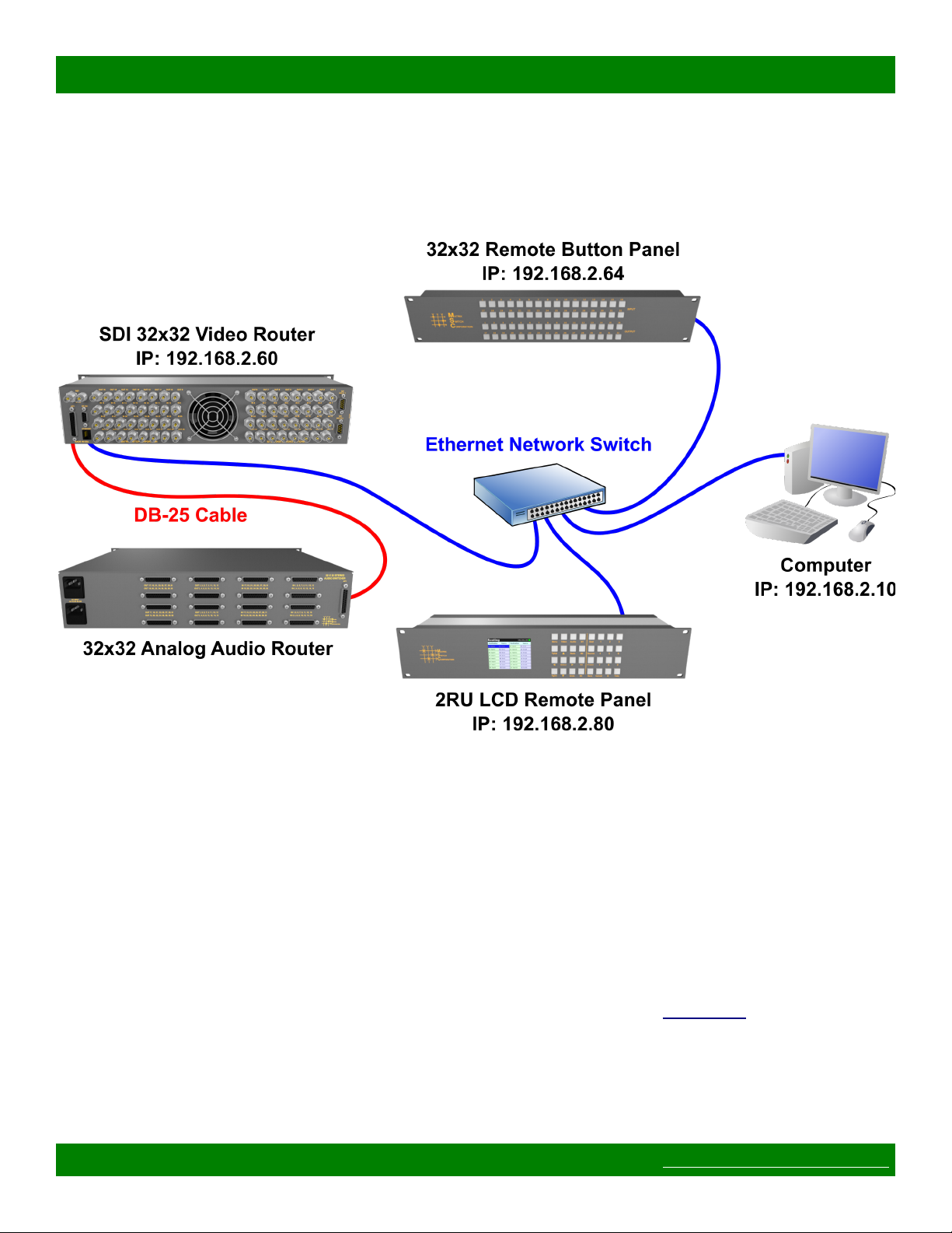
1.5.1 Installation Example
The following diagram is of a simple installation example consisting of a 32x32 SDI Video Router, with a
secondary level 32x32 Analog Audio router connected via the AFV DB-25 interface, a 32x32 Remote Button
Panel, a 2RU LCD Remote Panel and a Computer system.
1.6 Advanced Panel Configuration
Button panel interfaces (on local and remote panels) can be configured to control a subset of destinations,
sources and/or levels.
Example use scenarios
• Utilize an 8x1 remote panel to control a single destination of an 8x8 video router.
• Use the local panel of a 16x16 two level Video and Audio router to control Video only and an additional
16x16 remote panel to control Audio independently.
• Use a 4x4 panel to independently control 4 destinations of an 8x8 router and limit selectable sources to 4
sources.
The applicable settings for advanced panel control scenarios can be found on the Config Tab of the Web Page
Interface. Refer to that section for additional details.
Page 10 of 55 © 2013-2016 Matrix Switch Corporation www.matrixswitch corp.com
Page 11

2 Web page interface
2.1 Overview
MSC-CP16X16E Product Manual
Figure 1: Routing Tab
All Matrix Switch Corporation Router and Remote Panel systems include a built in web page that can be used
with standards compliant Javascript enabled web browsers, including but not limited to Firefox, Chrome, Safari
and recent versions of Internet Explorer.
Figure 1 shows the Routing tab of a 16x16 switcher with 2 levels with numbered outlines to aid in further
description below. The web page interface for other router systems is sized appropriately. Remote Panels show
only the Config and Command tabs.
Numbered sections in Figure 1
1. System name (can be assigned on the Config tab)
2. System firmware series and version
3. Tab navigation
4. Preset load drop down selection
5. Source connect buttons
6. Mute button (may not be available on all switchers and levels)
7. Currently selected destination (destination name followed by currently connected source names for both
levels).
2.2 Config Tab
Page 11 of 55 © 2013-2016 Matrix Switch Corporation www.matrixswitch corp.com
Page 12
MSC-CP16X16E Product Manual
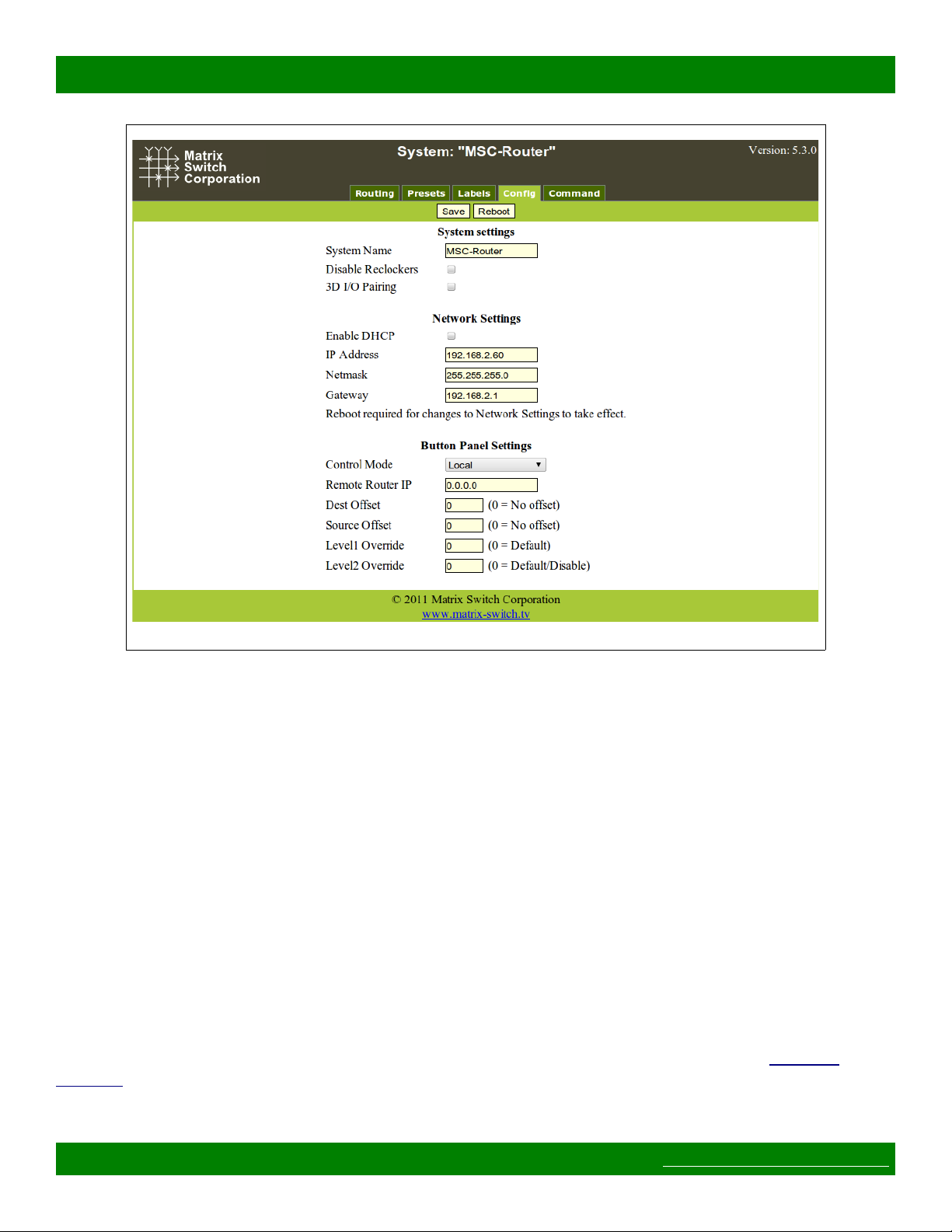
Figure 2: Config Tab
Figure 2 depicts the Config Tab as seen on a Router system beginning with Carina Series Firmware 5.3.0.
Configuration fields vary depending on router features, firmware version and if the device is a Remote Panel.
NOTE: After changing any configuration settings click the Save button. All Network Settings changes require
a Reboot of the device in order to take effect. After clicking Save, click the Reboot button to restart the device.
Remember to enter a new IP address into your Web browser's Location bar, if the device's IP address has
changed.
2.2.1 System Settings
• System Name – A descriptive name of the system (up to 15 characters), displayed at the top of the Web
Page interface which is helpful when managing multiple systems.
2.2.2 Network Settings
WARNING: DHCP should only be enabled or the IP Address or Netmask changed if one has an
understanding of TCP/IP network configuration. Once the save button is pressed and the system is rebooted any
changes to DHCP enable, the IP Address or the Netmask shall result in having to access the web page with the
new settings. If there are Matrix Switch Corporation remote control panels which access the system which has
been changed, they must also be reconfigured to use the new router IP address as well. See the Network
Planning section for more helpful information on planning your network.
Page 12 of 55 © 2013-2016 Matrix Switch Corporation www.matrixswitch corp.com
Page 13

MSC-CP16X16E Product Manual
• Enable DHCP – Check this box to enable DHCP. Disables IP Address, Netmask and Gateway fields as
these settings are obtained from the DHCP server.
◦ WARNING: A DHCP server must be present on your network for this to function properly. Using
DHCP allows for dynamic IP or fixed IP assignment from a central location (the DHCP server).
Using this option is only recommended if using fixed IP assignment based on the device's MAC
address or if there is a way to determine what IPs the devices get assigned. Otherwise it may
become difficult to determine what IP address to use when accessing the Web Page or utilizing other
Ethernet control interfaces.
• IP Address – The IP address of the system.
• Netmask – The system network mask.
• Gateway – The IP address of your network's Gateway, if applicable. Only necessary on systems which
access other systems outside of your network (a remote panel which accesses a router on a different
network for example).
2.2.3 Button Panel Settings
These settings control the operation of the device's button control panel interface (if applicable).
Four fields are provided for specifying what portion of a router is controlled by the button panel interface. This
provides added flexibility in defining what destinations and sources a panel controls. Some examples of use
include, using multiple 16x1 Remote Panels (16 source, 1 destination) to control individual destinations of a
16x4 Router (16 source, 4 destination). Another usage scenario would be to have 2 separate panels control
different levels of a Video/Audio Router.
• Remote Router IP – The IP address of the remote Router to control.
• Dest Offset – This setting determines what destination the button panel starts on. Defaults to 0 which
means the control panel starts on destination 1. Setting this value to 8 for example would cause the first
destination of the button panel to control destination 9.
• Source Offset – This setting determines what source the button panel starts on. Defaults to 0 which
means the control panel starts on source 1. Setting this value to 8 for example would cause the first
source of the button panel to control source 9. NOTE: If the currently active source cannot be
represented on the control panel, no source button LED will light.
• Level1 Override – This setting determines the primary control level of the button interface. It defaults
to 0 which is equivalent to level 1, usually a Video level. Setting this value to 2 for example would set
the primary level to be level 2 (usually Audio).
• Level2 Override – This setting determines the secondary control level of the button interface. It
defaults to 0, which if the Level1 Override is also 0 is equivalent to level 2, but if the Level1 Override is
a value other than 0, the secondary level control is disabled. Can only be assigned a non-zero value if
Level1 Override is also non-zero. If set to 3 for example, the secondary level would be level 3.
2.3 Command Tab
Page 13 of 55 © 2013-2016 Matrix Switch Corporation www.matrixswitch corp.com
Page 14

MSC-CP16X16E Product Manual
Figure 3: Command Tab
The Command Tab (Figure 3) provides access to the Mascot protocol interface. Commands are typed on the
Command text entry line followed by pressing the Enter key to execute them. The results will be displayed in
the text area below the command line. Clicking the Clear Output button will clear all command output in the
lower area.
See the section Mascot Control Protocol for more information.
Page 14 of 55 © 2013-2016 Matrix Switch Corporation www.matrixswitch corp.com
Page 15

MSC-CP16X16E Product Manual
3 Mascot Control Protocol
MASCOT (MAtrix Switch COrporation ProTocol) provides an ASCII text based command interface via
several different transports to control and get status from Matrix Switch Corporation devices. This command
protocol can be utilized for manual control or for integration with automation control systems.
Mascot command interface options
• Web Page Command Tab – The most convenient user command interface, which can be accessed using a
Web Browser on a Computer by the device's IP address.
• TCP/IP port 40 – A TCP/IP command interface is provided on port 40 which uses the device's Ethernet
connector as a physical transport and can be accessed via a telnet application.
3rd Party support
The MASCOT protocol contains a subset of the basic ISIS Protocol command set and therefore some 3rd party
equipment may work without modification using this protocol. For information about other third party control
system manufacturers who support MASCOT, contact Matrix Switch Corporation.
3.1 Protocol Changes
As new commands are added or other changes occur, the MASCOT protocol version is incremented. The
protocol revision can be obtained using the MascotVer command.
Protocol revision history
Mascot version 3.0
• Added System Parameter commands: Get, GetS, Set, SetA, and SetS commands.
• Current system parameters are defined in the System Parameter Table, superseding many configuration
commands.
• New commands for defining matrix I/O mapping: MapDest, and MapSrc commands.
• New commands for panel/GPIO command macros and conditions: PanelCmd, PanelCmdEn, and
PanelCond.
• Commands now grouped into Core Commands, Configuration Commands, and Miscellaneous
Commands.
Mascot version 2.4 (Carina Series Firmware 5.6.3)
• Added .MtxGroup, PanelDis, and PanelExtEn commands.
Mascot version 2.3 (Carina Series Firmware 5.5.1)
• Added Quit Command, SysType Command and Vars Command which have previously been supported
on the MSC-GCP2U32 only.
Mascot version 2.2 (Carina Series Firmware 5.5.0)
• The X Command now accepts a 0 valued wild card destination to switch all destinations to a given
source.
Page 15 of 55 © 2013-2016 Matrix Switch Corporation www.matrixswitch corp.com
Page 16

MSC-CP16X16E Product Manual
Mascot version 2.1 (Carina Series Firmware 5.3.0)
• New commands: PairIO – for paired I/O 3D support, PanelOfs – for defining remote panel I/O regions
to control, PanelRate – to set remote panel refresh rate, ReclkDis – for disabling SDI reclockers and
RemoteSync – for synchronizing two video router systems for 3D use.
• Added E12 “Unsupported command” error which is returned when a command is not supported by the
current system or settings.
• Added support for Line Feed character as a command terminator (to be compatible with older firmware).
Carriage Return should normally be used.
• Added “lock” (0x02) and “reclk” (0x04) to MtxCfg Command “flags” field.
3.2 Telnet Access
A telnet client can be used to access the command interface on TCP/IP port 40. Many operating systems come
with a Telnet client or one can be easily obtained. To control a device using Telnet the IP address and TCP/IP
port number will need to be supplied. This is typically added as arguments when executing the “telnet”
command via your operating system's command prompt or run dialog. Here is an example command to connect
to a device on the IP address 192.168.2.60 (press ENTER after the command):
telnet 192.168.2.60 40
Pressing the ENTER key after successfully connecting should display the command “>” prompt character.
3.3 Command Format
Commands consist of a command name, zero or more arguments separated by commas and a carriage return
(CR, ASCII 13 - the Enter key on a keyboard). Optionally multiple commands can be combined by separating
them with a '#' character and the command chain is terminated with a CR character. Spaces are not required
between arguments, but can be optionally supplied for readability. A space is also not required between
command names and their first argument, if the argument is numeric. Table 3 lists characters which have
special meaning in MASCOT commands.
# Multiple command separator, for chaining commands.
<CR> Carriage Return (ASCII 13), indicates the end of a command or chain of commands, Enter key.
<BS> Backspace character (ASCII 11), can be used to backspace characters in interactive command shells.
“ Used for double quoting string arguments.
' Used for single quoting string arguments.
Table 3: Special Command Characters
Command example
X1,1#X2,2#S<CR>
Connects Source 1 to Destination1 and Source 2 to Destination 2, followed by displaying the Active Routing
Page 16 of 55 © 2013-2016 Matrix Switch Corporation www.matrixswitch corp.com
Page 17

MSC-CP16X16E Product Manual
matrix status. The <CR> is the Carriage Return character.
3.3.1 Command Names
Command names consist of one or more alphabetical characters and are case insensitive. For convenience with
manual command entry they can also be matched using partial names. The first matching alphabetically sorted
command is used (for example: 'H', 'He', 'hEL' or 'Help' can be used to execute the Help command). However,
this feature should not be relied on with 3rd party integration, since a given partial command may execute a
different command as new ones are added to the protocol.
3.4 Response Format
Most command responses consist of one or more values separated by newlines and ending with the ‘>’ prompt
character. Newlines consist of a Carriage Return/New Line (CR LF) pair of characters (ASCII 13 followed by
ASCII 10).
The Prompt ‘>’
A prompt character ‘>’ is displayed each time a command or chain of commands is entered, to indicate
readiness to receive additional commands. If an error occurs in response to a command, an error will be
displayed prior to the prompt with the following format:
E00: Error message
>
00 will contain a 2 digit decimal error code.
Table 4 shows possible error codes which may be returned in response to commands.
Error # Message Description
E01 Token too long A command name or string argument was too long.
E02 Invalid command Invalid command name.
E03 Invalid argument One or more invalid argument values.
E04 Invalid destination Invalid matrix destination number.
E05 Invalid source Invalid matrix source number.
E06 Invalid level Invalid matrix level number.
E07 Invalid preset Invalid preset number.
E08 Unterminated string Double or single quoted string not terminated.
E09 Backspace limit
reached
E10 Buffer overflow Data exceeds maximum buffer length.
E11 Serial receive overrun One or more characters were lost on the serial interface.
E12 Unsupported command Command is not supported by the system or current configuration.
E13 I/O Error A general I/O error occurred.
Devices have a limited backspace buffer size, if too many characters are
backspaced and then more characters are appended, this error will occur.
Firmware 5.3.0 and newer.
Table 4: Error Codes
3.5 Command Arguments
Page 17 of 55 © 2013-2016 Matrix Switch Corporation www.matrixswitch corp.com
Page 18

MSC-CP16X16E Product Manual
Command arguments are separated into two categories: numeric and string arguments. These are further
explained in Table 5.
Numeric String
Decimal (123) 1 to 3 decimal digits Unquoted Commands with string arguments
automatically interpret argument as
string (spaces and commas not
allowed).
Hex (0x3D) 0xNN where NN are 2 hex digits
from 0-9, A-F or a-f
Table 5: Basic Argument Types
Arguments are shown in the Help command output surrounded by square brackets '[Arg]' or parenthesis '(Arg)'.
Square brackets indicate an optional argument and parenthesis indicate a required argument. Any optional
argument specified requires that all prior optional arguments are also specified. Table 6 lists currently used
command argument types.
Argument Valid Range Meaning
Boolean 0/1, T/F, True/False Boolean true or false value.
Cmd String MASCOT command.
Cond String Condition statement. See PanelCond C ommand.
Dest 1-N Destination number (N = Count of destinations)
IP D.D.D.D IP address string argument, specified as 4 decimal numbers from 0 to 255
separated by periods.
Json String JSON formatted string, the structure of which depends on the command.
The JSON string should be quoted in single quote characters when
specifying a JSON value in a command.
Label String A string label argument, max of 8 characters.
Lvl 1-N Level number (N = Count of system levels)
Netmask D.D.D.D Network mask string argument, specified as 4 decimal numbers from 0 to
255 separated by periods. Must be a valid IPv4 netmask.
Number Numeric value. Valid values depends on command.
Preset 0-9 Preset number (preset 0 is special Startup preset)
Parameter Parameter identifier. See System Parameters.
Src 1-N or 0 Source number (N = Count of sources), 0 acts as mute (if supported).
String String A generic string argument (max length depends on the command).
Value A general value. Value type depends on setting. See System Parameters.
Double quoted One or more characters surrounded
by double quotes (“An Argument”).
Single quoted One or more characters surrounded
by single quotes ('An Argument').
Table 6: Command Argument Types
3.6 System Parameters
Page 18 of 55 © 2013-2016 Matrix Switch Corporation www.matrixswitch corp.com
Page 19

MSC-CP16X16E Product Manual
MASCOT protocol version 3.0 adds commands for setting and querying configuration and other system
parameters. These commands greatly simplify the MASCOT command set and supersede several configuration
commands.
System parameter values can be set in Stored memory and/or Active memory. Stored values are loaded on
system startup. Active values are the current control values of the running system, but wont be retained after a
system restart if they differ from the Stored value.
Command Arguments Description
Get [Parameter] Query Active parameter values.
Get S [Parameter] Query Stored parameter values.
Set [Parameter][Value] Set Active/Stored parameter value (depends on parameter).
S etA [Parameter][Value] Set Active value of a parameter only.
Set S [Parameter][Value] Set Stored value of a parameter only.
Table 7: System Parameter Commands
Parameter identifiers are represented as one or more alphanumeric words separated by periods, representing a
tree structure similar to file folders or directories. Table 8 below describes the columns in the System Parameter
Table.
Parameter Parameter identifier consisting of one or more words separated by periods.
Value Value type, see the Command Arguments section for details.
Access Parameter access. R for Readable settings, W for writable settings, or RW for both.
Set Default parameter memory used with the Set Command. A for Active, S for Stored, or AS for
both. Commands which use only Stored memory require a reboot to become Active.
Table 8: System Parameter Table Columns
3.6.1 System Parameter Table
Parameter Value Access Set Description
ctl.mascot.ver String R Mascot version in the form MAJOR.MINOR (3.0 for example).
ctl.serial.baud Number RW AS RS-232 serial port baud rate in bits/second.
ctl.serial.log Boolean RW AS RS-232 serial port protocol log enable.
ctl.serial.proto String RW AS RS-232 serial port protocol selection (“mascot”, “svs”, etc).
ctl.serial2.baud Number RW AS RS-485 serial port baud rate in bits/second.
ctl.serial2.log Boolean RW AS RS-485 serial port protocol log enable.
ctl.serial2.proto String RW AS RS-485 serial port protocol selection (“mascot”, “svs”, etc).
mtx.serial Number R Current matrix serial number, incremented on every routing change.
Page 19 of 55 © 2013-2016 Matrix Switch Corporation www.matrixswitch corp.com
Page 20

MSC-CP16X16E Product Manual
mtx.sync Boolean RW AS Keep current routing state stored to preset 0. Effectively retains last
matrix routing state even after a restart or power cycle.
net.dhcp Boolean RW S Network interface DHCP enable.
net.gateway IP RW S Network gateway address.
net.ip IP RW S Network interface IP address.
net.mac MAC R Network interface MAC address.
net.netmask IP RW S Network interface mask.
pnl.cmdEn Boolean RW AS Panel command macro enable.
pnl.ip IP RW AS Remote IP address for panel interface to control.
sys.arch String R System architecture (“Pyxis”, “Carina”, “Lynx”, etc).
sys.firmware String R Firmware series and version (“Pyxis 1.1.7” for example).
sys.name String RW AS System name identifier.
3.7 Core Commands
This section outlines commands considered to be core MASCOT protocol commands and consists of matrix
routing, I/O label, preset, and other primary system commands.
Command Arguments Description
DestNames [Dest][Lvl][Label] Destination I/O names command.
E [0 | 1] Matrix connection echo enable command.
Firmware System firmware version.
Help Command help reference.
MascotVer Mascot protocol version.
MtxCfg [0-7] Current matrix config.
P [Preset] Recall a preset.
PAdd (Preset)(Dest)(Src)[Lvl] Add a connection to a preset.
PClr (Preset) Clear a preset to “No Change” values.
PsetNames [Preset][Label] Preset names command.
PSub (Preset)(Dest)[Lvl] Subtract a connection from a preset.
PView [Preset] View preset.
Quit Quit TCP/IP telnet session.
Reboot Reboot the system.
S [1] Matrix routing status.
SrcNames [Src][Lvl][Label] Source names command.
SysType System hardware series.
W [Preset] Store current matrix routing to a preset.
X [Dest][Src][Lvl] Perform a matrix connect operation.
3.8 Configuration Commands
Commands in this section are for system configuration and are not considered to be a core part of the MASCOT
protocol. There may be implementation and support variations between different system types. Many of these
Page 20 of 55 © 2013-2016 Matrix Switch Corporation www.matrixswitch corp.com
Page 21

MSC-CP16X16E Product Manual
commands have been superseded by System Parameters in Mascot protocol version 3.0.
Command Arguments Description
DHCP [0 | 1] DHCP enable.
FrameIP [IP] Remote router IP address the panel will control.
Gateway [IP] Network gateway IP address.
IP [IP] System IP address.
MAC MAC address.
MapDest [Dest][Dest][Lvl] Matrix destination remap command.
MapSrc [Src][Src][Lvl] Matrix source remap command.
MtxGroup [Number][Number] I/O grouping command.
NetMask [Netmask] Network mask.
PairIO [0 | 1] I/O pairing enable. Superseded by the MtxGroup command.
PanelCmd [Button][Cmd] Panel button/GPIO command macros.
PanelCmdEn [0 | 1] Enable panel button/GPIO command macros.
PanelCond [Button][Cond] Panel button/GPIO status conditions.
PanelDis [0 | 1] Internal panel button interface disable.
PanelExtEn [0 | 1] External panel interface enable (if available).
PanelOfs [Dest][Src][Lvl][Lvl] Button panel destination/source offsets and levels to control.
PanelRate [Number] Remote panel refresh rate.
SerBaud [Number] Query or assign serial baud rate.
SysName [String] System name.
Vars Query all system configuration variables.
WebPass (String) Assign web password.
3.9 Miscellaneous Commands
These additional commands consist of those which are not commonly used, not considered to be a core part of
the MASCOT protocol, and support is most likely to vary between system types and firmware versions.
Command Arguments Description
B (0 | 1) Reboot system into Bootloader, typically used for software update. A 0 or 1
value is required and selects the Bootloader IP address. A value of 0 uses
192.168.2.59 and 1 uses configured system IP.
C Query system matrix info, which is displayed in the format
DESTS,SRCS,LEVELS,FLAGS1,FLAGS2.
Superseded by the MtxCfg command.
LockStatus Get video lock status and rate detection information (not all HD router
systems are supported).
ReclkDis [0 | 1] Disable SDI reclockers (not all SDI router systems are supported).
RemoteSync [0 | 1] Query or assign remote router syncing. Useful for creating a 3D system out
of 2 routers.
3.10 Command Reference
This section documents each MASCOT command in detail. Please note that command availability may vary
between firmware series and versions. Details of availability are documented for each command.
Page 21 of 55 © 2013-2016 Matrix Switch Corporation www.matrixswitch corp.com
Page 22

MSC-CP16X16E Product Manual
3.10.1 B Command
Carina series only
The B command is used for rebooting the system into Bootloader for software updates. See the Software
Updates section for details.
3.10.2 C Command
Routers and MSC-GCP2U32 only
NOTE: Superseded by the MtxCfg Command.
The C command queries the matrix size. The response is in the format “Dests,Srcs,Levels,Flags1,Flags2”.
Where “Dests” is the count of system destinations, “Srcs” is the count of sources and “Levels” is the number of
system levels. The Flags1 and Flags2 fields are currently unused and will be 0.
Example for a 16x16 system with 2 levels
>C
16,16,2,0,0
>
3.10.3 DestNames Command
Routers and MSC-GCP2U32 only
Query or assign destination names. This command has 4 variations, described by the following table.
Destination names are saved and recalled on power up.
Command Description
DestNames Query all destination names.
DestNames DEST Query destination names for all levels of a given destination.
DestNames DEST, LEVEL Query the name of a specific destination and level.
DestNames DEST, LEVEL, LABEL Assign a label to a destination.
When querying names, labels are surrounded by double quotes and each level is separated by commas ',' (multilevel systems only) and each destination is separated by newlines. Secondary levels use empty strings to
indicate that the label of the first level should be used.
Examples
>DestNames
“Dest1”,”AudDest1”
“Dest2”,””
“Dest3”,””
“Dest4”,””
>DestNames 1
“Dest1”,”AudDest1”
>DestNames 1,2
“AudDest1”
>DestNames 1,2,””
Page 22 of 55 © 2013-2016 Matrix Switch Corporation www.matrixswitch corp.com
Page 23

MSC-CP16X16E Product Manual
>
The first 3 example commands are query commands. The last assigns an empty string to the second level of the
first destination (thereby indicating that the first level label should be used).
3.10.4 DHCP Command
NOTE: Superseded by the net.dhcp System Parameter.
Query or assign DHCP enable. A value of 0 disables DHCP client support and will therefore use the manual
values assigned via the IP, Netmask and Gateway commands. A value of 1 enables DHCP and will obtain the
values for the IP address, Netmask and Gateway from your DHCP server. This value is saved and recalled on
power up.
WARNING: A DHCP server must be present on your network for this to function properly. Using DHCP
allows for dynamic IP or fixed IP assignment from a central location (the DHCP server). Using this option is
only recommended if using fixed IP assignment by MAC address or if there is a way to determine what IPs the
Matrix Switch Corporation systems get assigned. Otherwise it may become difficult to determine what IP
address to use when accessing the Web Page or other control interfaces. In the event that the IP address or
Netmask of a system is unknown, consult the Unknown IP Address section for this device.
Command Description
DHCP Query DHCP enable.
DHCP 0 | 1 Set DHCP enable (0 to disable, 1 to enable)
Examples to query and then enable DHCP
>DHCP
0
>DHCP 1
>
3.10.5 E Command
Routers and MSC-GCP2U32 only
Query or assign matrix routing changes echo enable. A value of 0 disables this feature. A value of 1 will cause
all matrix routing changes to be echoed in the form of an X command: “Xd,s[,l]”. Where 'd' is the destination
number, 's' is the source number and 'l' is the optional level number. This is useful for diagnostic purposes or
automation software which would like to receive synchronous matrix routing state updates.
NOTE: Enabling this feature may slow down the system significantly during excessive matrix routing changes
(especially when enabled on a serial port interface). Also of note is that this option takes effect only while the
system remains powered (serial port) or for the duration of the connection (TCP/IP telnet sessions). This
command is not supported by the HTTP web command interface.
Command Description
Page 23 of 55 © 2013-2016 Matrix Switch Corporation www.matrixswitch corp.com
Page 24

MSC-CP16X16E Product Manual
E Query matrix echo enable.
E 0 | 1 Set matrix echo enable (0 to disable, 1 to enable).
Examples to query and then enable matrix echo
>E
0
>E 1
>
3.10.6 Firmware Command
NOTE: Superseded by the sys.firmware System Parameter.
Query the system firmware series and version.
Example
>Firmware
Pyxis 1.1.7
>
3.10.7 FrameIP Command
NOTE: Superseded by the pnl.ip System Parameter.
Query or assign the remote router IP address. Usually only used on Remote Panel devices or in conjunction
with the RemoteSync Command to create a dual router 3D system. Sets the IP address of the Router system
which the button panel will connect to and control (or which the router will synchronize to when using the
RemoteSync command). This can also be enabled on Router systems with a local button panel to configure the
Router's panel to control a different Router (set to 0.0.0.0 by default to disable remote control and control the
Router device itself). This setting is saved and recalled on power up.
Command Description
FrameIP Query IP address of remote Router system to control.
FrameIP IP Set IP address of remote Router system to control (use 0.0.0.0 on Router systems to disable
remote control).
Example to query and assign the remote Router IP
>FrameIP
192.168.2.60
>FrameIP 192.168.2.61
>
3.10.8 Gateway Command
NOTE: Superseded by the net.gateway System Parameter.
Query or assign the network Gateway IP address. This is usually only needed on Remote Panel systems which
control a Router device on a different network. This setting is saved and recalled on power up.
Page 24 of 55 © 2013-2016 Matrix Switch Corporation www.matrixswitch corp.com
Page 25

MSC-CP16X16E Product Manual
Command Description
Gateway Query IP address of network Gateway.
Gateway IP Set IP address of network Gateway.
3.10.9 Get Command
Protocol version 3.0
The Get command is used for querying values of currently Active system parameter values. See the System
Parameter Table for a list of currently defined parameters. This command supersedes many individual
configuration commands.
NOTE: This command queries Active values of parameters which may differ from values in Stored memory.
Values in Stored memory are loaded at system startup and can be queried with the GetS Command. See System
Parameters for more details.
Command Description
Get Display all system parameter Active values. Output consists of one parameter per line with
the parameter identifier separated by an equals ‘=’ character and the value.
Get Parameter Display the Active value of a single parameter or a subset of parameters under a given
parameter node.
Examples of querying all parameters, “mtx” parameters, and “net.ip” parameter.
>Get
ctl.mascot.ver=2.3
ctl.serial.baud=115200
ctl.serial.log=0
ctl.serial.proto=mascot
ctl.serial2.baud=115200
ctl.serial2.log=0
ctl.serial2.proto=mascot
mtx.serial=1
mtx.sync=0
net.dhcp=0
net.gateway=192.168.2.1
net.ip=192.168.2.60
net.mac=00:50:C2:8B:DF:FE
net.netmask=255.255.255.0
pnl.cmdEn=1
pnl.ip=0.0.0.0
sys.arch=Pyxis
sys.descr=
sys.firmware=Pyxis 1.1.7
sys.name=MSC-Router
>Get mtx
mtx.serial=1
mtx.sync=0
Page 25 of 55 © 2013-2016 Matrix Switch Corporation www.matrixswitch corp.com
Page 26

MSC-CP16X16E Product Manual
>Get net.ip
net.ip=192.168.2.60
>
3.10.10 GetS Command
Protocol version 3.0
Gets system parameter values in Stored memory. The Get Command can be used to query current Active values
of parameters and can also be referenced for more details.
Command Description
GetS Display all system parameter Stored values. Output consists of one parameter per line with
the parameter identifier separated by an equals ‘=’ character and the value.
GetS Parameter Display the Stored value of a single parameter or a subset of parameters under a given
parameter node.
3.10.11 Help Command
Display command reference information.
3.10.12 IP Command
NOTE: Superseded by the net.ip System Parameter.
Query or assign the system IP address. This setting is saved and recalled on power up.
WARNING: Maintaining the ability to access a device's web page and for Remote Panel devices to be able to
communicate with Routers requires that the IP address is known, valid and systems are configured to be on the
same IP network. In the event that the IP address of a system is unknown refer to the Unknown IP Address
section for this device.
Command Description
Ip Query IP address of the system.
Ip IP Set IP address of the system.
Example querying and assigning the IP address
>IP
192.168.2.60
>IP 192.168.2.61
>
3.10.13 LockStatus Command
Routers only
Query the video lock status and video rate of a Video Router's outputs. This command is only supported on
some Router systems. Unsupported systems will return an “Unsupported command” error on version 2.1 and
Page 26 of 55 © 2013-2016 Matrix Switch Corporation www.matrixswitch corp.com
Page 27

MSC-CP16X16E Product Manual
newer protocol versions and blank output on older versions.
Command Description
LockStatus Displays Video lock status and rate detection for outputs. Format is one decimal number
per output (0: Unlocked, 1: SD, 2: HD).
Example for a 16x4 system (SD, HD, Unlocked, Unlocked)
>LockStatus
1,2,0,0
>
3.10.14 MAC Command
NOTE: Superseded by the net.mac System Parameter.
Query system Ethernet MAC address.
Command Description
MAC System Ethernet MAC address in hh:hh:hh:hh:hh:hh where each hh is a pair of hex digits.
Example
>MAC
00:50:C2:8B:DF:FE
>
3.10.15 MapDest Command
Routers only – Protocol version 3.0
Query or assign matrix destination mappings. Destination mappings provide a means to remap logical
destinations to different physical destinations for an added level of convenience when allocating and defining
system I/Os.
Command Description
MapDest Display destination matrix map. Only destinations are shown which have been
remapped. One destination number per line is shown separated by a colon ‘:’
and the destinations which are substituted for each level separated by commas.
MapDest Dest Display mapping of a single destination.
MapDest Dest1 Dest2 Assign a destination mapping on all levels for Dest1 to physical Dest2.
MapDest Dest1 Dest2 Level Assign a destination mapping on a single level for Dest1 to physical Dest2.
Examples
>MapDest
1:4,4
2:3,2
>MapDest 1
Page 27 of 55 © 2013-2016 Matrix Switch Corporation www.matrixswitch corp.com
Page 28

MSC-CP16X16E Product Manual
1:4,4
>
>MapDest 1, 5
>
>MapDest 1, 6, 2
>
The examples above are for a 2 level router. The rst example queries the entire
destination map, which shows that destination 1 is remapped to physical destination 4
on both levels and destination 2 is remapped to destination 3 on the rst level and
destination 2 on the second level. The second example queries the mapping for a single
destination. The third example maps destination 1 to physical destination 5 on all
levels. The fourth example maps destination 1 to physical destination 6 on the second
level only.
3.10.16 MapSrc Command
Routers only – Protocol version 3.0
Query or assign matrix source mappings. Source mappings provide a means to remap logical sources to
different physical sources for an added level of convenience when allocating and defining system I/Os.
Command Description
MapSrc Display source matrix map. Only sources are shown which have been
remapped. One source number per line is shown separated by a colon ‘:’ and
the sources which are substituted for each level separated by commas.
MapSrc Src Display mapping of a single source.
MapSrc Src1 Src2 Assign a source mapping on all levels for Src1 to physical Src2.
MapSrc Src1 Src2 Level Assign a source mapping on a single level for Src1 to physical Src2.
Examples
>MapSrc
1:4,4
2:3,2
>MapSrc 1
1:4,4
>
>MapSrc 1, 5
>
>MapSrc 1, 6, 2
>
The examples above are for a 2 level router. The rst example queries the entire source
map, which shows that source 1 is remapped to physical source 4 on both levels and
source 2 is remapped to source 3 on the rst level and source 2 on the second level.
The second example queries the mapping for a single source. The third example maps
Page 28 of 55 © 2013-2016 Matrix Switch Corporation www.matrixswitch corp.com
Page 29

MSC-CP16X16E Product Manual
source 1 to physical source 5 on all levels. The fourth example maps source 1 to
physical source 6 on the second level only.
3.10.17 MascotVer Command
NOTE: Superseded by the ctl.mascot.ver System Parameter.
Query Mascot protocol version. This is useful for software which interacts with a device using the Mascot
protocol and wants to discover what protocol version is in use. The returned value is either an integer such as
"2" or major and minor version numbers separated by a period, such as "2.3".
Example
>MascotVer
2.3
>
3.10.18 MtxCfg Command
Routers and MSC-GCP2U32 only - Protocol Version: 2.0
Query matrix configuration. This command replaces the C command and provides the ability to query the
matrix dimensions, labels, current matrix state and preset data. The information to return is specified by the
sum of the flags values listed in the following table:
Flag Information Fields in JSON data
1 Return names (Destination, Source and
Preset).
destNames, srcNames and
psetNames
2 Return matrix routing state. state
4 Return preset routing data. psetData
The returned data is JSON formatted data (see www.json.org for details).
If no arguments are specified then a simple format is returned consisting of an array of arrays (one per level)
with 3 integer numbers specifying the destination count, source count and flags of the level. The flags value is
the sum of one or more values from the Flags table below.
Flags
Name Value Description
mute 1 Mute support.
lock 2 Video lock status query support
reclk 4 Reclocker disable support.
Example
>MtxCfg
[[8,8,3][4,8,0]]
Page 29 of 55 © 2013-2016 Matrix Switch Corporation www.matrixswitch corp.com
Page 30

MSC-CP16X16E Product Manual
The example above is simple output (no arguments) for a matrix with 2 levels, the first has 8 destinations, 8
sources and supports mute and lock status query (1 + 2 = 3). The second level has 4 destinations, 8 sources and
does not support mute, lock status query or reclocker disable.
If an argument is specified (0-7), then a more descriptive JSON structure is returned, of the following form
(newlines and spaces added as a visual aid, but are not necessarily part of the response):
{
“version” : 1,
“status” : “STATUS”,
“levels” :
[
{
“name” : “NAME”,
“type” : “TYPE”,
“destCount” : DEST_COUNT,
“srcCount” : SRC_COUNT,
“flags” : “FLAGS”,
“destNames” : [ “NAME”, ”NAME”, ... ],
“srcNames” : [ “NAME”, ”NAME”, ... ],
“state” : [ SRC, SRC, ... ],
“psetData” : [ [ SRC, ... ], [ SRC, ... ], ... ]
},
...
],
“psetNames” : [ “NAME”, ”NAME”, ... ]
}
Table of information on values in capital letters above:
Label Description
STATUS Matrix status: OK, UPDATING, DISCONNECT or ERROR. Returned if the matrix is
OK, updating (from a remote router for example), one or more remote routers
disconnected or a general error (remote router in error status for example) respectively.
NAME Descriptive name of a level, destination, source or preset (8 chars or less).
TYPE Level type: VIDEO, AUDIO, HD, VGA, 3G, ANALOG or AES. Used for general video,
general audio, HD video, VGA video, 3G HD video, analog audio or AES digital audio
respectively.
DEST_COUNT Count of destinations for the level.
SRC_COUNT Count of sources for the level.
FLAGS A space separated list of flag keywords indicating support for various features, as defined
by the Name column in the Flags table above.
SRC Source values for matrix state and preset data. Values start from 1, 0 represents mute and
-1 represents “No Change” (for preset data only).
Example - Newlines and spaces added to response as a visual aid.
Page 30 of 55 © 2013-2016 Matrix Switch Corporation www.matrixswitch corp.com
Page 31

MSC-CP16X16E Product Manual
>MtxCfg7
{
“version” : 1,
“status” : “OK”,
“levels” :
[
{
“name” : “Level1”,
“type” : “VIDEO”,
“destCount” : 4,
“srcCount” : 4,
“flags” : “mute”,
“destNames” : [ “Dest1”, ”Dest2”, “Dest3”, “Dest4” ],
“srcNames” : [ “Src1”, ”Src2”, “Src3”, “Src4” ],
“state” : [ 1, 2, 3, 4 ],
“psetData” :
[
[1,2,3,4], [1,1,1,1], [-1,-1,-1,-1], [-1,-1,-1,-1],
[-1,-1,-1,-1], [-1,-1,-1,-1], [-1,-1,-1,-1], [-1,-1,-1,-1],
[-1,-1,-1,-1], [-1,-1,-1,-1]
]
},
],
“psetNames” :
[
“Startup”,”Preset1”,”Preset2”,”Preset3”,”Preset4”,
”Preset5”,“Preset6”,”Preset7”,”Preset8”,”Preset9”
]
}
The example output above is a typical response for a 4x4 Video router. Current matrix routing is “straight
through”, 10 presets are defined (1st is straight through, 2nd is mapped all to source 1, and all other presets have
not been assigned (No Change). Note that future protocol versions may support more than 10 presets and
therefore may return information for more or less than 10 presets for the psetData and psetNames arrays.
3.10.19 MtxGroup Command
Routers only - Protocol Version: 2.4
Query or assign I/O grouping. This setting is saved and recalled on power up.
The I/O grouping feature is used to combine multiple inputs and outputs. Combined grouped inputs and outputs
then behave as if they were a single I/O, which changes the size of the router matrix accordingly (matrix size
divided by group count), and matrix routing changes update the grouped I/Os simultaneously. Group counts are
assigned on a per level basis, allowing for different I/O grouping for separate levels (for example separate video
and audio levels). Real world examples of I/O grouping include: dual channel 3D video and combining
multiple audio channels (4 AES digital audio streams for example).
Command Description
MtxGroup Query current I/O grouping.
MtxGroup LEVEL1 Set level 1 I/O grouping (0 or 1 disables grouping).
Page 31 of 55 © 2013-2016 Matrix Switch Corporation www.matrixswitch corp.com
Page 32

MSC-CP16X16E Product Manual
MtxGroup LEVEL1, LEVEL2 Set level 1 and level 2 I/O grouping (0 or 1 disables grouping).
Example querying and assigning I/O grouping
>MtxGroup
1,1
>MtxGroup 2,4
>MtxGroup
2,4
>
The first example MtxGroup command shows that I/O grouping is disabled on both levels of a 2 level system.
The second command configures the system for dual I/O grouping on level 1 and quad I/O grouping on level 2.
On an example 16x16 two level router this would result in an 8x8 matrix on level 1 and a 4x4 matrix on level 2.
3.10.20 NetMask Command
NOTE: Superseded by the net.netmask System Parameter.
Query or assign the system network mask value. This value is related to the IP address of the system and is
used for IP communications over the Ethernet network. This setting is saved and recalled on power up.
WARNING: Maintaining the ability to access a device's web page and for Remote Panel devices to be able to
communicate with Routers requires that the IP address is known, valid and systems are configured to be on the
same IP network. In the event that the IP address or Netmask of a system is unknown, consult the Unknown IP
Address section for this device.
Command Description
NetMask Query network mask value.
NetMask NETMASK Set network mask value.
Example querying and assigning netmask
>NetMask
255.255.255.0
>NetMask 255.255.255.192
>
3.10.21 P Command
Routers and MSC-GCP2U32 only
Recalls a preset. Each Router system contains 10 presets numbered 0 through 9 which can store the entire
matrix routing state or one or more single destination connections. Preset 0 is recalled on system power up.
Command Description
P PRESET Recall a preset.
Example to recall preset 1
Page 32 of 55 © 2013-2016 Matrix Switch Corporation www.matrixswitch corp.com
Page 33

MSC-CP16X16E Product Manual
>P 1
>
3.10.22 PAdd Command
Routers and MSC-GCP2U32 only
Preset add command. Adds a connection to a preset. This can be used to incrementally create a preset without
changing the active matrix routing. 0 can be used for SRC for Mute (if supported). This command stores preset
information which is retained and available through system power cycles.
Command Description
PAdd PRESET, DEST, SRC Add a connection of SRC to DEST on PRESET for all levels.
PAdd PRESET, DEST, SRC, LEVEL Add a connection of SRC to DEST/LEVEL on PRESET.
Example
>PAdd 1,2,3
>PAdd 1,3,0,2
>
The first command adds a connection from Source 3 to Destination 2 in Preset 1. The second command Mutes
Destination 3 on Level 2 in Preset 1.
3.10.23 PairIO Command
Routers only - Protocol Version: 2.1
NOTE: Superseded by MtxGroup C ommand.
I/O pairing is used for pairing destinations/sources for 3D support. When activated a router will appear to have
half the number of physical destinations and sources. A given matrix crosspoint change will cause 2
destinations to be changed. Each odd destination/source is paired with the next highest even number
destination/source. This option is stored and recalled on power on. When enabling this feature on a 4x4 video
router for example, it would appear as a 2x2 3D router where destination 1 & 2 are paired and 3 & 4 are paired,
likewise for sources. This setting is stored and recalled on power up.
Command Description
PairIO Query current value of I/O pairing configuration.
PairIO 0 | 1 Enable or disable I/O pairing (0: disable, 1: enable)
Example
>PairIO
0
>PairIO 1
>
The first command queries the current state of I/O pairing, the second enables it.
Page 33 of 55 © 2013-2016 Matrix Switch Corporation www.matrixswitch corp.com
Page 34

MSC-CP16X16E Product Manual
3.10.24 PanelCmd Command
Protocol Version: 3.0
Query and assign panel button/GPIO command macros. This system provides a means to easily implement
custom functionality in response to a panel button press or GPIO auxiliary port contact closure (button or switch
to ground). Panel buttons and GPIO pins are specified by numeric ID.
Panel buttons are numbered beginning with ID number 1. Panel button order depends on the panel, but
generally has the top left button as button 1, followed by number 2 in the lower left corner, number 3 in the top
second column, continuing to alternate between top and bottom rows till the last button (lower right hand
corner).
GPIO auxiliary pins start with ID number 65 for GPIO pin 1.
NOTE: Panel commands must be enabled with the PanelCmdEn Command or by setting the pnl.cmdEn S ystem
P arameter to activate them.
Command Description
PanelCmd Query all assigned panel button/GPIO commands.
PanelCmd Button Query a single panel button/GPIO command.
PanelCmd Button Command Assign a panel button/GPIO command. Assigning a blank command to a
button or GPIO pin will clear the command (two consecutive single or double
quotes represents an empty string).
Examples
>PanelCmd
1 P0
2 P1
65 P0
>PanelCmd 1
1 P0
>PanelCmd 66,”P1”
>PanelCmd 66,””
>
The first example above queries the currently assigned panel/GPIO commands, which shows that button
number 1 and 2 have P0 and P1 commands assigned respectively, which recalls preset 0 and preset 1, and GPIO
pin 1 (GPIO pins start at 65) will recall preset 0. The second command queries the panel command for button
1. The third command assigns the command “P1” to GPIO pin 2 (ID 66). The fourth command clears the
command assigned to GPIO pin 2.
3.10.25 PanelCmdEn Command
Protocol Version: 3.0
NOTE: Superseded by the pnl.cmdEn System Parameter.
Query and assign panel button/GPIO command macro and condition subsystem enable. This command is used
Page 34 of 55 © 2013-2016 Matrix Switch Corporation www.matrixswitch corp.com
Page 35

MSC-CP16X16E Product Manual
to enable or disable button and GPIO commands and conditions. See PanelCmd and PanelCond commands for
more details.
Command Description
PanelCmdEn Query panel button/GPIO command and conditions enable.
PanelCmd 0 | 1 Enable or disable panel button/GPIO command and conditions (0: disable, 1: enable).
Examples for querying and enabling panel command/conditions
>PanelCmdEn
0
>PanelCmdEn 1
>
3.10.26 PanelCond Command
Protocol Version: 3.0
Query and assign panel button/GPIO status and indicator conditions. Panel button/GPIO conditions are a
counterpart to Panel Commands and provide a means to easily implement custom status to light panel buttons or
change logic states on output GPIO pins. Panel buttons and GPIO pins are specified by numeric ID.
Panel buttons are numbered beginning with ID number 1. Panel button order depends on the panel, but
generally has the top left button as button 1, followed by number 2 in the lower left corner, number 3 in the top
second column, continuing to alternate between top and bottom rows till the last button (lower right hand
corner).
NOTE: Condition statements are not currently fully defined and at the moment consists of only a matrix preset
matching condition, which is specified as “Pn” where n is the preset number. For example P0 would cause the
assigned button LED to light or GPIO to become a logic high value if the current matrix state matches preset 0.
A future revision will add support for a more robust conditional instruction language.
GPIO auxiliary pins start with ID number 65 for GPIO pin 1.
NOTE: Panel commands and conditions must be enabled with the PanelCmdEn Command or by setting the
pnl.cmdEn S ystem P arameter to activate them.
Command Description
PanelCond Query all assigned panel button/GPIO conditions.
PanelCond Button Query a single panel button/GPIO condition.
PanelCond Button Condition Assign a panel button/GPIO condition. Assigning a blank condition to a
button or GPIO pin will clear the condition (two consecutive single or double
quotes represents an empty string).
Examples
Page 35 of 55 © 2013-2016 Matrix Switch Corporation www.matrixswitch corp.com
Page 36

MSC-CP16X16E Product Manual
>PanelCond
1 P0
2 P1
67 P0
>PanelCond 1
1 P0
>PanelCond 68,”P1”
>PanelCond 68,””
>
The first example above queries the currently assigned panel/GPIO conditions, which shows that button number
1 and 2 have P0 and P1 conditions assigned respectively, which lights the button LEDs when the current matrix
routing matches preset 0 or preset 1 respectively, and GPIO pin 3 (GPIO pins start at 65) will output a logic 1 if
the matrix matches preset 0. The second command queries the panel condition for button 1. The third
command assigns the condition “P1” to GPIO pin 4 (ID 68). The fourth command clears the condition assigned
to GPIO pin 4.
3.10.27 PanelDis Command
Protocol Version: 2.4
Query or assign internal button interface panel disable setting. This setting is stored and recalled on power up.
Command Description
PanelDis Query internal panel disable setting.
PanelDis 0 | 1 Assign internal panel disable setting (0: enable, 1: disable)
Examples
>PanelDis
0
>PanelDis 1
>
The first command queries the current panel disable setting (0: enabled). The second command disables the
internal panel interface.
3.10.28 PanelExtEn Command
Carina series only - Protocol Version: 2.4
Query or assign external button interface panel enable setting (if applicable – not all router devices have an
external panel interface). This setting is stored and recalled on power up.
Command Description
PanelExtEn Query external panel interface enable setting.
PanelExtEn 0 | 1 Assign external panel interface enable setting (0: disable, 0: enable)
Examples
Page 36 of 55 © 2013-2016 Matrix Switch Corporation www.matrixswitch corp.com
Page 37

MSC-CP16X16E Product Manual
>PanelExtEn
0
>PanelExtEn 1
>
The first command queries the current external panel interface setting (0: disabled). The second command
enables the external panel interface.
3.10.29 PanelRate Command
Protocol Version: 2.1
For changing remote button panel refresh rate. When a button panel is configured to control a remote router the
current connection status is refreshed at regular intervals. This command can be used to increase or decrease
the rate, which is saved and recalled on system power up. The default refresh rate is 5 seconds. This value is
stored and recalled on power up.
Command Description
PanelRate Query current panel refresh rate (in seconds).
PanelRate RATE Set remote panel refresh rate in seconds.
Examples
>PanelRate
5
>PanelRate 1
>
The first command queries the current panel refresh rate, which returns 5 (default). The second command sets
the refresh rate to be 1 second.
3.10.30 PClr Command
Routers and MSC-GCP2U32 only
Clear a preset. For Preset 0 this sets all Destinations to Source 0. Other Presets are assigned “No Change” to
all Destinations. This command stores preset information which is available through system power cycles.
Command Description
PClr PRESET Clear a preset.
Example to clear preset 1
>PClr 1
>
3.10.31 ProtoSer Command
Carina series only
Page 37 of 55 © 2013-2016 Matrix Switch Corporation www.matrixswitch corp.com
Page 38

MSC-CP16X16E Product Manual
NOTE: Superseded by the ctl.serial.proto and ctl.serial2.proto System Paramete rs.
Query or assign the serial protocol. The only available option is currently the case insensitive value "Mascot",
however additional control protocols may be added in the future. Value is stored and recalled on power up.
Command Description
ProtoSer Query the protocol used on the serial port.
ProtoSer PROTO Assign the protocol used on the serial port (the only valid value is
currently "Mascot").
Examples
>ProtoSer
Mascot
>
3.10.32 PsetNames Command
Routers and MSC-GCP2U32 only
Query or assign preset names. Preset names are stored and recalled on power up.
Command Description
PsetNames Query all preset names.
PsetNames PRESET Query a single preset name.
PsetNames PRESET, LABEL Assign a preset label.
When querying names, labels are surrounded by double quotes and separated by newlines.
Examples
>PsetNames
“Startup”
“Preset1”
“Preset2”
“Preset3”
“Preset4”
“Preset5”
“Preset6”
“Preset7”
“Preset8”
“Preset9”
>PsetNames 1
“Preset1”
>PsetNames 1,”MyPreset”
>
The first 2 example commands are query commands. The last assigns “MyPreset” to Preset 1.
Page 38 of 55 © 2013-2016 Matrix Switch Corporation www.matrixswitch corp.com
Page 39

MSC-CP16X16E Product Manual
3.10.33 PSub Command
Routers and MSC-GCP2U32 only
Preset subtract command. Removes a connection in a preset by setting a Destination or Destination/Level to
“No Change”. This can be used to incrementally create a preset without changing the active matrix routing.
This command changes preset data which is stored and persists through power cycles.
Command Description
PSub PRESET, DEST Remove any existing connection to DEST in PRESET for any level.
PSub PRESET, DEST, LEVEL Remove any existing connection to DEST/LEVEL in PRESET.
Example
>PSub 1,2
>PSub 1,3,2
>
The first command removes any connection to Destination 2 in Preset 1. The second command removes any
connection to Destination 3/Level 2 on Preset 1.
3.10.34 PView Command
Routers and MSC-GCP2U32 only
View presets. Displays the content of one or all presets.
The format of the returned output is “1:S1[,S2] 2:S1[,S2] ...” where the 1: and 2: are incrementing destination
values, followed by one or more source values (depending on the number of system levels).
Special source values
• '-' indicates “No Change”, which causes no changes to the given Destination/Level.
• 0 indicates “Mute”
Command Description
PView Display all presets.
PView PRESET Display a single PRESET.
Example on a 16x4 system with 2 levels
>PView 1
1:1,1 2:2,2 3:6,7 4:0,>
The above example shows that Preset 1 would cause Destination 1 to be connected to Source 1 for both levels,
Destination 2 to be connected to Source 2 for both levels, Destination 3 to be connected to Source 6 for Level 1
and Source 7 for Level 2 (break away) and Destination 4 to be Muted for Level 1 and “No Change” would be
made for Level 2.
Page 39 of 55 © 2013-2016 Matrix Switch Corporation www.matrixswitch corp.com
Page 40

MSC-CP16X16E Product Manual
3.10.35 Reboot Command
Instructs the system to reboot, which is done after a brief delay. Ensures that all outstanding data writes are
written to non-volatile memory, prior to the reboot.
3.10.36 ReclkDis Command
Routers only - Protocol Version: 2.1
Command for disabling or enabling SDI reclockers. Not all router systems support this option. Value is saved
and recalled on power up.
Command Description
ReclkDis Query current value of reclocker disable.
ReclkDis 0 | 1 Enable or disable reclockers (0 or 1 respectively).
Examples
>ReclkDis
0
>ReclkDis 1
>
The first command above queries the current reclocker disable value which returns 0 (the default, reclockers
enabled). The second command disables the reclockers.
3.10.37 RemoteSync Command
Routers only - Protocol Version: 2.1
Command to enable syncing matrices of two router systems. Usually used for creating a 3D matrix from two
router systems, which will result in one router controlling the left 3D channels and the other router controlling
the right channels. When enabled, this option synchronizes matrix crosspoint changes to the router IP address
assigned with the FrameIP Command. This command should only be enabled with one of the two routers (the
primary router). This value is stored and recalled on power up.
Command Description
RemoteSync Query current value of remote router syncing.
RemoteSync 0 | 1 Enable or disable remote router syncing (1 or 0 respectively).
Examples
>RemoteSync
0
>RemoteSync 1
>FrameIP 192.168.2.61
>
The first command in the above examples queries the current value of the remote sync option, which returns 0
Page 40 of 55 © 2013-2016 Matrix Switch Corporation www.matrixswitch corp.com
Page 41

MSC-CP16X16E Product Manual
(disabled, the default). The second command enables remote syncing and the final command sets the IP address
of the router to sync (secondary router).
3.10.38 S Command
Routers and MSC-GCP2U32 only
Query the current matrix routing state. Source values for all levels of every destination are shown. This
command without an argument is equivalent to the X Command with no arguments. If an argument value of '1'
is supplied, then the matrix state is displayed with labels. The state of each destination is displayed, one per
line, in the format:
“DestNLvl1”:”SrcLvl1”,”DestNLvl2”:”SrcLvl2”,...
Example
>S1
“Dest1”:”Src4”,”Dest1”:”Src4”
“Dest2”:”Src3”,”Dest2”:”Src3”
“Dest3”:”Src2”,”Dest3”:”Src2”
“Dest4”:”Src1”,”Dest4”:”Src4”
The example above is output from a two level (Video and Audio for example) 4x4 matrix with sources routed in
reverse order, except destination 4, which has a 2nd level break away which is routed from source 4.
3.10.39 SerBaud Command
NOTE: Superseded by the ctl.serial.baud and ctl.serial2.baud System Paramete rs.
Query or assign the RS-232 serial port baud rate. The default value is 115200. This value is stored and recalled
on power up.
Command Description
SerBaud Query the current serial port baud rate.
SerBaud BAUD Set the serial port baud rate.
Examples
>SerBaud
115200
>SerBaud 9600
>
The first example command queries the serial baud rate value which is the default of 115200 and the second
command sets it to 9600 baud.
3.10.40 Set Command
Protocol version 3.0
The Set command is used for assigning values to system parameters. See the System Parameter Table for a list
of currently defined parameters. This command supersedes many individual configuration commands.
Page 41 of 55 © 2013-2016 Matrix Switch Corporation www.matrixswitch corp.com
Page 42

MSC-CP16X16E Product Manual
NOTE: This command may set Active and/or Stored parameter values. Behavior depends on the parameter and
is defined in the System Parameter Table. Values in Stored memory are loaded at system startup. See System
Parameters for more details.
Command Description
Set List all parameter identifiers which can be set, one per line.
Set Parameter Value Set a parameter’s Active and/or Stored value (depends on parameter).
Examples of listing all writable parameters and setting the “net.ip” parameter.
>Set
ctl.serial.baud
ctl.serial.log
ctl.serial.proto
ctl.serial2.baud
ctl.serial2.log
ctl.serial2.proto
dbg.i2cAckFails
dbg.i2cArbLosses
dbg.i2cBusErrors
dbg.i2cOverruns
dbg.i2cTimeouts
dbg.i2cResets
mtx.sync
net.dhcp
net.gateway
net.ip
net.mac
net.netmask
pnl.cmdEn
pnl.ip
sys.descr
sys.name
sys.type
>Set net.ip 192.168.2.60
>
3.10.41 SetA Command
Protocol version 3.0
The SetA command is used for setting system parameter Active values only. Values set with this command will
take effect immediately, but will not be retained through a system restart.
NOTE: Some parameters may not be assignable in Active memory. Such parameters must be set in Stored
memory followed by a system restart to activate the changes. See System Parameters for more details.
Command Description
SetA List all parameter identifiers which can be set in Active memory, one per line.
SetA Parameter Value Set a parameter’s Active value.
Page 42 of 55 © 2013-2016 Matrix Switch Corporation www.matrixswitch corp.com
Page 43

MSC-CP16X16E Product Manual
3.10.42 SetS Command
Protocol version 3.0
The SetS command is used for setting system parameter Stored values only. Values set with this command will
not take effect until the system is restarted.
NOTE: Some parameters may not be assignable in Stored memory, for example if it does not make sense to
recall a value on start up. See System Parameters for more details.
Command Description
SetS List all parameter identifiers which can be set in Stored memory, one per line.
SetS Parameter Value Set a parameter’s Stored value.
3.10.43 SrcNames Command
Routers and MSC-GCP2U32 only
Query or assign source names. This command has 4 variations, described by the following table. Source names
are stored and recalled on power up.
Command Description
SrcNames Query all source names.
SrcNames SRC Query source names for all levels of a given source.
SrcNames SRC, LEVEL Query the name of a specific source and level.
SrcNames SRC, LEVEL, LABEL Assign a label to a source.
When querying names, labels are surrounded by double quotes and each level is separated by commas ',' (multilevel systems only) and each source is separated by newlines. Secondary levels use empty strings to indicate
that the label of the first level should be used.
Examples
>SrcNames
“Src1”,”AudSrc1”
“Src2”,””
“Src3”,””
“Src4”,””
>SrcNames 1
“Src1”,”AudSrc1”
>SrcNames 1,2
“AudSrc1”
>SrcNames 1,2,””
>
The first 3 example commands are query commands. The last assigns an empty string to the second level of the
first source (thereby indicating that the first level label should be used).
Page 43 of 55 © 2013-2016 Matrix Switch Corporation www.matrixswitch corp.com
Page 44

MSC-CP16X16E Product Manual
3.10.44 SysName Command
NOTE: Superseded by the sys.name System Paramete r.
Query or assign system name. The system name is provided for convenience when managing multiple Matrix
Switch Corporation systems. This value is stored and recalled on power up.
Command Description
SysName Query system name.
SysName STR Set system name (up to 15 characters).
Example for querying and assigning system name
>SysName
MSC-Router
>SysName “MyRouter”
>
3.10.45 SysType Command
Protocol Version: 2.3
NOTE: Superseded by the sys.arch System Paramete r.
Query the system series type, which is currently defined as one of the following values:
Value Series name
0 Carina
1 Lupus
2 Lynx
3 Hydra
4 Pyxis
NOTE: This command was not added until version 2.3 of the Mascot protocol. On previous versions, this
command is available on the MSC-GCP2U32 LCD panel but not other Matrix Switch Corporation systems.
When determining the system type, if executing the command returns an Invalid Command error, the system
series can be assumed to be Carina.
Command Description
SysType Query the system hardware series.
Examples
>SysType
E01: Invalid command
>SysType
2
>
Page 44 of 55 © 2013-2016 Matrix Switch Corporation www.matrixswitch corp.com
Page 45

MSC-CP16X16E Product Manual
The first example command shows the response that would be received on a Carina series system with older
firmware not supporting the SysType command, the second example is what might be returned by an MSCGCP2U32 LCD panel.
3.10.46 Vars Command
Protocol Version: 2.3
Display all system configuration variables. Useful in serial terminal or telnet sessions to view all configuration
values.
Command Description
Vars Display all system configuration parameters. Note that variables
consisting of JSON data simply show the string JSON, to keep the
output concise. The output consists of one line per variable, with the
variable name followed by an equals '=' and then the value (not
quoted).
Examples
>Vars
DefaultProfile=1
DHCP=1
DNSPri=0.0.0.0
DNSSec=0.0.0.0
Firmware=1.5.1
Gateway=192.168.2.1
IP=192.168.2.80
Mac=00:00:00:00:00:00
MascotVer=2
MtxProfiles=JSON
Netmask=255.255.255.0
Profile=1
SerBaud=115200
SerProto=Mascot
SysName=MSC-Panel
SysType=2
>
The example above shows a typical output of the Vars command for an MSC-GCP2U32 LCD panel.
3.10.47 W Command
Routers and MSC-GCP2U32 only
Write current matrix routing state to a preset. Recalling the preset later will restore the routing matrix to the
same state. This command modifies preset data which persists through power cycles.
Command Description
W PRESET Write current matrix routing state to PRESET.
Page 45 of 55 © 2013-2016 Matrix Switch Corporation www.matrixswitch corp.com
Page 46

MSC-CP16X16E Product Manual
Example to save state to preset 1
>W 1
>
3.10.48 WebPass Command
Assign a web password to password protect the web page interface. The serial and TCP/IP port Mascot protocol
control is not protected by this password. This value is stored and recalled on power up.
Command Description
WebPass STR Set web page password (blank to disable)
Examples of setting and clearing web page password
>WebPass SeCr3t
>WebPass “”
>
3.10.49 X Command
Routers and MSC-GCP2U32 only
Query or make changes to the matrix routing state. This command comes in several variations described by the
following table.
Command Description
X Query complete routing state (equivalent to S Command).
X DEST Query connected sources for DEST for all levels.
X DEST, SRC Connect SRC to DEST for all levels.
X DEST, SRC, LEVEL Connect SRC to DEST/LEVEL.
When querying connection state, sources for each level are separated by commas (multi-level systems only) and
are displayed for each destination and separated by newlines.
The value 0 can be used for DEST to switch all destinations to a given source. A level may also be specified to
isolate switching a single level of all destinations. (Protocol Version 2.2)
The value 0 can be used for SRC to Mute a destination (if supported for a given level).
Examples
>X
1,1
2,2
3,8
0,4
Page 46 of 55 © 2013-2016 Matrix Switch Corporation www.matrixswitch corp.com
Page 47

MSC-CP16X16E Product Manual
>X 3
3,8
>X 3,4
>X 4,0,2
>
In the above examples the first command queries the matrix routing state (typical of a 16x4 system for
example), the second command queries destination 3 only, the third command connects source 4 to destination 3
on all levels and the fourth command mutes destination 4 level 2.
Command stacking
Command stacking is especially useful for the X command, since it allows for several connections to be
performed at the same time.
Example
>X1,4#X2,3#X3,2#X4,1
>
The above would connect source 4 to destination 1, source 3 to destination 2, source 2 to destination 3 and
source 1 to destination 4 for all levels.
Page 47 of 55 © 2013-2016 Matrix Switch Corporation www.matrixswitch corp.com
Page 48

MSC-CP16X16E Product Manual
4 Software Updates
The procedure for updating software (also called firmware) on Matrix Switch Corporation devices is determined
by the hardware series. The hardware series can be most easily determined by looking at the top right hand
corner of the web page interface, which will indicate the hardware series (Carina, Pyxis, Lynx, Lupus, etc) and
the version of the firmware.
It is recommended that software updates are only performed in order to resolve an issue or gain a desired
feature. While the software update procedures have been designed to be resistant to failure, there is still a risk
of a device becoming inoperable in the event that an update is interrupted. Consult the Troubleshooting section
for information on device recovery in the event this occurs.
4.1 Software Update on Carina Series Devices
There are two basic methods of performing a software update: Power On Software Update (POSU) and
Command Software Update (CSU). Both methods use the TFTP protocol over the device's Ethernet port.
CSU is recommended if the device is on a different IP network than the default 192.168.2.x and the update
computer's IP is already configured on that network. POSU is needed if the device's software gets corrupted
(due to a failed update attempt) or if sending a Mascot command to the device is problematic.
Software update method comparison
• POSU uses a fixed update IP address of 192.168.2.59 whereas CSU uses the device's configured IP
address.
• POSU should be available even if a device's firmware gets corrupted from a previous update attempt,
whereas CSU will likely no longer be possible.
• POSU has a shorter TFTP “update time window” of 5 seconds and the TFTP transfer has to occur within
this period after power cycling the device. This means the PC needs to be in close proximity of the
device, remote power control be possible or coordination with someone to power cycle the device when
initiating the TFTP transfer. Because of the shorter update window, a cross over Ethernet cable is not
recommended, due to potential delay in the physical Ethernet link becoming active.
• CSU requires an extra step of a Mascot command being sent to the device.
4.1.1 Software Update Requirements
To perform a software update, the following is required:
1. A computer connected to the same Ethernet network as the device being updated.
2. A TFTP client program installed on the computer. See TFTP Software section for details.
3. The device to update with its Ethernet port connected to the same network as the PC.
4. A firmware file image for the device from Matrix Switch Corporation. The file name is of the form
MSC-Carina-Firmware-x.x.x.hex, where x.x.x is the version number.
5. See Upgrading from version 4.x.x or older firmware if applicable.
4.1.2 Power on Software Update
This method requires that a TFTP transfer is initiated immediately after powering up the device.
Page 48 of 55 © 2013-2016 Matrix Switch Corporation www.matrixswitch corp.com
Page 49

MSC-CP16X16E Product Manual
NOTE: A cross over cable is not recommended for this update method, due to the probability that the delay of
the physical Ethernet link becoming active exceeds the TFTP update time window. Please use a network switch
and connect the PC and device to it.
Steps for executing a Power On Software Update:
1. Ensure that the Software Update Requirements are met.
2. Configure the PC for the IP address 192.168.2.58 or another unique IP on the same 192.168.2.x IP
network (except 192.168.2.59). Make sure that no other system on the network is using 192.168.2.59 or
the IP assigned to the PC.
3. Prepare the TFTP program to transfer the firmware file to the device, but do not initiate the transfer yet.
See the section TFTP Software for details.
4. Power on the device (power cycle it if it is already on).
5. Immediately after powering on the device, initiate the TFTP transfer (hit ENTER on the tftp command,
etc), there is only a 5 second time window to initiate the transfer.
6. If the transfer does not complete successfully within 30 seconds, retry from step 3.
4.1.3 Command Software Update
This method uses the device's already assigned IP address and the execution of a Mascot command to initiate
the software update. If the IP is unknown, use the Power On Software Update method or refer to the Unknown
IP A ddress section.
NOTE: The software update time window is 30 seconds for this method, so a cross over cable should be OK,
but if in doubt, make sure there is an Ethernet switch between the device and update PC.
Steps for executing a Command Software Update:
1. Ensure that the Software Update Requirements are met.
2. Configure the PC for a unique IP address on the same IP network as the device (if not already). Make
sure that there are no IP conflicts with the PC or device.
3. Prepare the TFTP program to transfer the firmware file to the device, but do not initiate the transfer yet.
See the section TFTP Software for details.
4. Power up the device being updated, if not already operating.
5. Use one of the following methods to send a Mascot command to the device:
◦ If the device already contains version 5 firmware (mid year 2011), connect to the device's web page
interface by using a web browser, entering it's IP address into the browser's Location bar and
pressing ENTER. Navigate to the command tab, where the command will be typed into the text
entry field at the top.
◦ Use a telnet client to connect to port 40 on the device. For many command line telnet clients
(Windows XP, Mac OSX, Linux, etc) this can be accomplished by opening up a command terminal
and typing the following command (replace 192.168.2.60 with the actual IP of the device): “telnet
192.168.2.60 40”. Once connected press ENTER and make sure a “>” prompt character is displayed
(indicating that a valid connection has been established). The software update command can then be
typed in the telnet session.
◦ If the device is a Matrix Switch Corporation router, then you can connect a serial cable between it
and the PC. Use a terminal program, such as Hyperterm, and configure the serial settings for 9600
Page 49 of 55 © 2013-2016 Matrix Switch Corporation www.matrixswitch corp.com
Page 50

MSC-CP16X16E Product Manual
Baud 8N1 (8 data bits, No parity, 1 stop bit). Press ENTER to confirm the connection (a '>' prompt
character should be displayed). The software update command can then by typed in the serial
connection window.
◦ If you are unable to establish a Mascot command connection, use the Power On Software Update
method.
6. Type the Mascot command “B1” followed by ENTER, utilizing one of the above Mascot connection
methods.
7. A few seconds after entering the above command, initiate the TFTP transfer (hit ENTER on the tftp
command, etc), there is a 30 second time window to initiate the transfer.
8. If the transfer does not complete successfully within 30 seconds, retry from step 3.
4.2 Software failsafe recovery procedure
In the event the device software becomes inoperable and a regular software update cannot be performed, due to
a failed software update or abnormal data corruption, this section can be consulted for the applicable software
recovery procedure. Prior to following this procedure, please check the following, in the event that the issue is
not related to software functionality:
• Ensure the proper power supply is being used and is connected to a good power source.
• Check that applicable power indicators/panel buttons are lit and device hardware appears to be otherwise
in working order.
• If network communication with the device is not working, ensure network cabling and interconnect
hardware is functioning, ensure the proper IP address is being used to connect to the device, is unique on
the network, and that the system being used to connect to the device has a unique IP on the same
network subnet. Consult the Unknown IP address section for details on recovering from an unknown IP
address.
After checking that these conditions are met, the following procedure can be used to recover from a corrupted
firmware issue, depending on the system type.
Carina series systems require that the Power on Software Update procedure is used if the normal system
firmware is unaccessible. Please consult that section for additional details.
4.3 TFTP Software
There are many different options for TFTP client programs, the choice of which depends on what operating
system you are using on the computer being used to perform the TFTP transfer from. The following sections
list some options for various operating systems.
4.3.1 Windows
Windows XP has a TFTP client installed and enabled by default. For newer versions of Windows the TFTP
client must be enabled using the following procedure:
1. Navigate to Start → Control Panel → Programs and Features.
2. Click Turn Windows features on or off on the left side of the interface
3. Scroll to the TFTP Client option in the list and check the check box next to it.
4. Click OK
Page 50 of 55 © 2013-2016 Matrix Switch Corporation www.matrixswitch corp.com
Page 51

MSC-CP16X16E Product Manual
To use the tftp utility on Windows:
1. Copy the firmware image file to the Desktop.
2. Open a windows command prompt (Start → Run and type “cmd” followed by the ENTER key).
3. Change to the directory where the firmware image is with the command “cd Desktop” followed by the
ENTER key.
4. Type the following command to prepare the TFTP transfer (but don't hit ENTER yet):
tftp -i 192.168.2.59 put MSC-Carina-Firmware-x.x.x.hex
5. Make sure to replace 192.168.2.59 with the device's IP address if the update procedure being used
utilizes the device’s assigned IP and replace MSC-Carina-Firmware-x.x.x.hex with the correct version
number of the file.
6. Pressing ENTER will initiate the TFTP transfer. Make sure to perform the necessary actions to prepare
the system for an update, prior to attempting the transfer.
7. The TFTP program will indicate if the transfer was successful or not.
4.3.2 Mac OS X
Mac OS X comes with a tftp client. It is accessed from the Terminal application.
To use the tftp application on Mac OSX:
1. Copy the firmware file to somewhere easily accessible from the Terminal application, for example your
home directory at /Users/your_user_name/
2. Open a terminal: Applications -> Utility -> Terminal
3. Use 'cd' commands to change to the location of the firmware file, for example ‘cd
/Users/your_user_name/’ followed by the ENTER key.
4. Execute the tftp command with the IP address of the device (make sure to use the device's configured IP
if the update method being used utilizes the devices IP address):
tftp 192.168.2.59
5. Execute the following commands from within the tftp program, pressing ENTER after each line, except
the last one, to prepare the TFTP transfer:
binary
put MSC-Carina-Firmware-x.x.x.hex
6. Make sure to replace MSC-Carina-Firmware-x.x.x.hex with the correct version number of the file.
7. Pressing ENTER after the put command will initiate the TFTP transfer. Make sure to perform the
necessary actions to prepare the system for an update, prior to attempting the transfer.
8. The TFTP program will indicate if the transfer was successful or not.
9. If the transfer failed (timed out, etc), retry the put command or quit the application (type 'quit' and
ENTER) and start over from step 4.
4.3.3 Linux
The tftp application can easily be installed with your distributions package manager from a terminal, below are
Page 51 of 55 © 2013-2016 Matrix Switch Corporation www.matrixswitch corp.com
Page 52

MSC-CP16X16E Product Manual
some example commands for various distributions.
Commands for installing tftp on different Linux distributions:
• Ubuntu: sudo apt install tftp-hpa
• Fedora: yum install tftp
• Suse: smart install tftp
Using the tftp application on Linux:
1. Copy the firmware file to somewhere easily accessible from the Terminal application, for example the
Desktop.
2. Open a Terminal command line application (CTRL-ALT-T will do this on many desktop environments).
3. Use 'cd' commands to change to the directory where the firmware file is located, for example (if the
firmware file is on your desktop) ‘cd ~/Desktop’ followed by the ENTER key.
4. Execute the tftp command with the IP address of the device (make sure to use the device's configured IP
if the update method being used utilizes the devices IP address):
tftp 192.168.2.59
5. Execute the following commands from within the tftp program, pressing ENTER after each line, except
the last one, to prepare the TFTP transfer:
binary
put MSC-Carina-Firmware-x.x.x.hex
6. Make sure to replace MSC-Carina-Firmware-x.x.x.hex with the correct version number of the file.
7. Pressing ENTER after the put command will initiate the TFTP transfer. Make sure to perform the
necessary actions to prepare the system for an update, prior to attempting the transfer.
8. The TFTP program will indicate if the transfer was successful or not.
9. If the transfer failed (timed out, etc), retry the put command or quit the application (type 'quit' and
ENTER) and start over from step 4.
Page 52 of 55 © 2013-2016 Matrix Switch Corporation www.matrixswitch corp.com
Page 53

MSC-CP16X16E Product Manual
5 Troubleshooting
This section contains information on frequent issues and ways to troubleshoot them.
5.1 Unknown IP address
In the event that the IP address of a device is unknown, the following procedure can be used to retrieve it:
This remote panel device can be forced to have the default IP address of 192.168.2.64 and netmask
255.255.255.0. This is done by flipping dip switch 8 to the ON position on the back of the panel (a reboot or
power cycle is required for the changes to take effect). A computer system can then be configured with an IP
address on the same IP subnet and the webpage configuration can be loaded for viewing and changing the IP
address as described in the section Accessing The Web Page Interface. The device will remain at the default IP
address until the dip switch is turned off and the system is rebooted or power cycled, at which point it will
revert to the value stored in the system configuration.
5.2 No Ethernet link when connected to network switch
This device utilizes a 10 BaseT Ethernet interface. In the event that the device is connected to a network switch
and no physical link is established, please try the following:
1. Ensure that the Ethernet cable is good (try it with another known good Ethernet device or swap the cable
for a known good cable).
2. Ensure proper power supply is being used for the system (5 VDC 2 Amp)
3. If the switch is a managed switch, try forcing 10 BaseT for the Ethernet port the device is connected to,
instead of rate auto detection.
5.3 Unexpected reboots
If the device is rebooting unexpectedly (detectable on routers when the routing state gets reset to preset 0),
make sure the correct power supply is being used with the device (5 VDC 2 Amp).
5.4 Glossary
• Active Routing – The current routing state of a Router's Matrix.
• Destination – A Video or Audio destination (output from a Router device). Numbered starting from 1.
• Input – Synonymous with Source.
• IP – Stands for Internet Protocol. Base protocol of the Internet which can also be used on LANs. This
protocol uses 4 byte addresses (IPv4) written in "quad dot" format, which is four decimal numbers
separated by periods (192.168.2.60 for example).
• LAN – Stands for Local Area Network. Refers to a single local Ethernet network, usually consisting of
a single IP subnet.
• Level – Router devices may contain multiple Video and Audio levels. Level numbers start from 1.
• Mascot Protocol – An abbreviation of MAtrix Switch COrporation proTocol. An ASCII text based
protocol for interfacing to Matrix Switch Corporation devices.
• Matrix – Used when referring to a Router's entire routing state.
Page 53 of 55 © 2013-2016 Matrix Switch Corporation www.matrixswitch corp.com
Page 54

MSC-CP16X16E Product Manual
• Mute – When supported, a destination can be muted, which for video means the output is turned off and
for audio means it is silenced.
• Output – Synonymous with Destination.
• Preset – Matrix Switch Corporation Router devices provide 10 presets which store matrix Routing
connections. When a preset is “recalled” zero or more matrix connections are changed based on the
content of the Preset. Numbered starting from 0. Preset 0 is special in that it is recalled on system
startup.
• Remote Panel – Matrix Switch Corporation Remote Panels connect to Router devices for remote
control with touch buttons.
• Router – A Video/Audio Routing device routes one or more sources to one or more destinations (not to
be confused with a Network router, which is referred to as a Network Switch in this manual).
• Simple Panel – A Matrix Switch Corporation Remote Panel which has buttons only.
• Smart Panel – A Matrix Switch Corporation Remote Panel which comes equipped with an LCD screen
interface.
• Source – A Video or Audio source (input to a Router device). Numbered starting from 1.
• TCP – Stands for Transport Control Protocol. This protocol is used by Matrix Switch Corporation
devices for remote panel control, the MASCOT network interface and the web page interface.
Page 54 of 55 © 2013-2016 Matrix Switch Corporation www.matrixswitch corp.com
Page 55

MSC-CP16X16E Product Manual
6 Matrix Switch Corporation Warranty
MSC provides the following limited warranty with its products:
1. MSC warrants that the equipment it manufactures is free from defects in material and workmanship.
2. This warranty begins on the day the product is shipped from MSC and shall be in effect for two years.
3. If the product is found to be defective, MSC shall at its option:
a) Provide free replacement parts.
b) Repair the unit at MSC's facilities.
c) Repair the unit at the customer's location.
d) Exchange the product for a product of the same type.
MSC shall make every reasonable effort to support critical emergencies by supplying no-cost loan equipment while the
defective unit is being repaired.
4. Customer bears the cost of shipping products returned to MSC under this warranty; however, MSC shall bear the cost
of shipping repaired products or replacement parts to the customer.
5. Any customer returning a product for repair shall first obtain from MSC a Return Material Authorization (RMA)
number which shall be placed on the outside of the shipping package.
6. This warranty does not apply if the product has been damaged by accident, abuse, misuse, misapplication or
modification.
EXCEPT AS SET FORTH ABOVE, NO OTHER WARRANTIES ARE EXPRESSED OR IMPLIED, INCLUDING BUT
NOT LIMITED TO, ANY IMPLIED WARRANTIES OF MERCHANTABILITY OR FITNESS FOR A PARTICULAR
PURPOSE. MSC EXPRESSLY DISCLAIMS ALL EXPRESS OR IMPLIED WARRANTIES NOT STATED HEREIN.
IN THE EVENT THE PRODUCT IS NOT FREE FROM DEFECTS AS WARRANTED ABOVE, THE PURCHASER'S
SOLE REMEDY SHALL BE REPLACEMENT OR REPAIR AS PROVIDED ABOVE. UNDER NO
CIRCUMSTANCES WILL MSC BE LIABLE TO THE PURCHASER OR ANY USER FOR ANY DAMAGES
INCLUDING INCIDENTAL OR CONSEQUENTIAL DAMAGES, EXPENSE, LOST PROFITS, LOST SAVINGS OR
OTHER DAMAGES ARISING OUT OF THE USE OF, OR INABILITY TO USE THE PRODUCT, EVEN IF MSC
HAS BEEN ADVISED OF THE POSSIBILITY OF SUCH DAMAGES.
To the extent this warranty conflicts with local law, local law shall only apply to such conflict.
Matrix Switch Corporation
Website: www.matrixswitch corp . com
Email: info@matrixswitch corp.com
Toll free: (800) 764-4084
Phone: (530) 477-9122 (Grass Valley, California)
Page 55 of 55 © 2013-2016 Matrix Switch Corporation www.matrixswitch corp.com
 Loading...