

Page 1

Page 2

Page 3

Digital Video Recorder
i
WARNING
RISK OF ELECTRIC SHOCK
DO NOT OPEN
WARNING: TO REDUCE THE RISK OF ELECTRIC SHOCK,
DO NOT REMOVE COVER (OR BACK).
NO USER-SERVICEABLE PARTS INSIDE.
REFER SERVICING TO QUALIFIED
SERVICE PERSONNEL.
The lightning flash with arrowhead symbol, within an equilateral triangle, is intended to alert
the user to the presence of uninsulated "dangerous voltage" within the product’s enclosure
that may be of sufficient magnitude to constitute a risk of electric shock.
The exclamation point within an equilateral triangle is intended to alert the user to the presence
of important operating and maintenan ce (servicing) instructions in the literature accompanying
the appliance.
COMPLIANCE NOTICE OF FCC:
THIS EQUIPMENT HAS BEEN TESTED AND FOUND TO COMPLY WITH THE LIMITS FOR A CLASS A DIGITAL
DEVICE, PURSUANT TO PART 15 OF THE FCC RULES. THESE LIMITS ARE DESIGNED TO PROVIDE
REASONABLE PROTECTION AGAINST HARMFUL INTERFERENCE WHEN THE EQUIPMENT IS OPERATED IN
A COMMERCIAL ENVIRONMENT. THIS EQUIPMENT GENERATES, USES, AND CAN RADIATE RADIO
FREQUENCY ENERGY AND IF NOT INSTALLED AND USED IN ACCORDANCE WITH THE INSTRUCTION
MANUAL, MAY CAUSE HARMFUL INTERFERENCE TO RADIO COMMUNICATIONS. OPERATION OF THIS
EQUIPMENT IN A RESIDENTIAL AREA IS LIKELY TO CAUSE HARMFUL INTERFERENCE, IN WHICH CASE
USERS WILL BE REQUIRED TO CORRECT THE INTERFERENCE AT THEIR OWN EXPENSE.
WARNING: CHANGES OR MODIFICATIONS NOT EXPRESSLY APPROVED BY THE PARTY RESPONSIBLE FOR
COMPLIANCE COULD VOID THE USER’S AUTHORITY TO OPERATE THE EQUIPMENT.
THIS CLASS OF DIGITAL APPARATUS MEETS ALL REQUIREMENTS OF THE CANADIAN INTERFERENCECAUSING EQUIPMENT REGULATIONS.
The information in this manual is believed to be accurate as of the date of publication. We are not responsible for any
problems resulting from the use thereof. The information contained herein is subject to change without notice. Revisions
or new editions to this publication may be issued to incorporate such changes.
Page 4
User’s Manual
ii
Important Safeguards
1. Read Instructions
All the safety and operating instructions should be read before the
appliance is operated.
2. Retain Instructions
The safety and operating instructions should be retained for future
reference.
3. Cleaning
Unplug this equipment from the wall outlet before cleaning it. Do not
use liquid aerosol cleaners. Use a damp soft cloth for cleaning.
4. Attachments
Never add any attachments and/or equipment without the approval of
the manufacturer as such additions may result in the risk of fire, electric
shock or other personal injury.
5. Water and/or Moisture
Do not use this equipment near water or in contact with water.
6. Ventilation
Place this equipment only in an upright position. This equipment has an
open-frame Switching Mode Power Supply (SMPS), which can cause a
fire or electric shock if anything is inserted through the ventilation holes
on the side of the equipment.
7. Accessories
Do not place this equipment on an unstable cart, stand or table. The
equipment may fall, causing serious injury to a child or adult, and
serious damage to the equipment. Wall or shelf mounting should follow
the manufacturer's instructio ns, and s hould use a mountin g kit appro ved
by the manufacturer.
This equipment and cart combination should be moved with care. Quick
stops, excessive force, and uneven surfaces may cause the equipment
and cart combination to overturn.
8. Power Sources
This equipment should be operated only from the type of power source
indicated on the marking labe l. If you are not sure o f the type of power,
please consult your equipment dealer or local power company.
9. Power Cords
Operator or installer must remove power and TNT connections before
handling the equipment.
10. Lightning
For added protection for this equipment during a lightning storm, or when
it is left unattended and unused for long periods of time, unplug it fr om the
wall outlet and disconnect the antenna or cable system. This will prevent
damage to the equipment due to lightning and power-line surges.
11. Overloading
Do not overload wall outlets and exte nsion cords a s this can resul t in the
risk of fire or electric shock.
12. Objects and Liquids
Never push objects of any kind through openings of this equipment as they
may touch dangerous voltage points or short out parts that could result in a
fire or electric shock. Never spill liquid of any kind on the equipment.
13. Servicing
Do not attempt to service thi s equipment y ourself. Refer a ll servicing t o
qualified service personnel.
14. Damage requiring Service
Unplug this equipment from the wall outlet and refer servicing to
qualified service personnel under the following conditions:
A. When the power-supply cord or the plug has been damaged.
B. If liquid is spilled, or objects ha ve fallen into the equipment.
C. If the equipment has been exposed to rain or water.
D. If the equipment does not operate normally by following the oper ating
instructions, adjust only those controls that are covered by the operating
instructions as an improper adjustment of other controls may result in
damage and will often require extensive work by a qualified technician
to restore the equipment to its normal operation.
E. If the equipment has been dropped, or the cabinet damaged.
F. When the equipment exhibits a disti nct change in performance ─ this
indicates a need for service.
15. Replacement Parts
When replacement parts are required, be sure the ser vice tec hnician has
used replacement parts specified by the manufacturer or that have the same
characteristics as the original part. Unauthorized substitutions may result
in fire, electric shock or other hazards.
16. Safety Check
Upon completion of any service or repairs to this equipment, ask the service
technician to perform safety checks to determ
ine that the equipment is in
proper operating condition.
17. Field Installation
This installation should be made by a qualified service person and
should conform to all local codes.
18. Correct Batteries
Warning: Risk of explosion if battery is replaced by an incorrect type.
Dispose of used batteries according to the instructions.
19. Tmra
A manufacturer’s maximum recommended ambient temperature (Tmra)
for the equipment must be specified so that the customer and installer may
determine a suitable maximum operating environment for the equipment.
20. Elevated Operating Ambient Temperature
If installed in a closed or multi-unit rack assembly, the operating ambient
temperature of the rack environment may be greater t han room am bient.
Therefore, consideration should be given to installing the equipment in an
environment compatible with the manufacturer’s maximum rated am bient
temperature (Tmra).
21. Reduced Air Flow
Installation of the equipment in the rack should be such that the amount
of airflow required for safe operation of the equipment is not compromised.
22. Mechanical Loading
Mounting of the equipment in the rack should be such that a hazardous
condition is not caused by uneven mechanical loadin g.
23. Circuit Overloading
Consideration should be given to connection of the equipment to supply
circuit and the effect that overloading of circuits might have on over current
protection and supply wiring. Appropri ate consi deratio n of equip ment
nameplate ratings should be used when addressing this concern.
24. Reliable Earthing (Grounding)
Reliable grounding of rack mounted equipment should be maintained.
Particular attention should be given to supply connections other than direct
connections to the branch circuit (e.g., use of power strips).
WEEE (Waste Electrical & Electronic Equipment)
Correct Disposal of This Product
(Applicable in the European Union and other European countries with separate collection systems)
This marking shown on the product or its literature, indicates that it should not be disposed with other household wastes at the
end of its working life. To prevent possible harm to the environment or human health from uncontrolled waste disposal, please
separate this from other types of wastes and recycle it responsibly to promote the sustainable reuse of material resources.
Household users should contact either the retailer where they purchased this product, or their local government office, for
details of where and how they can take this item for environmentally safe recycling.
Business users should contact their supplier and check the terms and conditions of the purchase contract. This product should
not be mixed with other commercial wastes for disposal.
Page 5

Digital Video Recorder
iii
Table of Contents
Chapter 1 — Introduction ........................................................................................................... 1
Feature ................................................................................................................................... 1
Technical Overview ................................................................................................................ 1
Chapter 2 — Installation ............................................................................................................. 3
Package Contents .................................................................................................................. 3
Required Installation Tools .................................................................................................... 3
Video Input......................................................................................................................... 3
Video Loop Through .......................................................................................................... 4
RS485 Port ........................................................................................................................ 4
Alarm Input/Output ............................................................................................................ 4
Network Port ...................................................................................................................... 4
RS232C Port ..................................................................................................................... 5
Audio In/Out ....................................................................................................................... 5
Video Out ........................................................................................................................... 5
Factory Reset Switch ......................................................................................................... 5
Power Cord Connector ...................................................................................................... 5
Chapter 3 — Configuration ........................................................................................................ 7
Front Panel Controls .............................................................................................................. 7
Camera Buttons (1 to 16) .................................................................................................. 8
Power LED......................................................................................................................... 8
HDD LED ........................................................................................................................... 8
Alarm Out LED .................................................................................................................. 8
Network LED ..................................................................................................................... 8
Clip Copy LED ................................................................................................................... 9
PANIC Button .................................................................................................................... 9
ALARM Button ................................................................................................................... 9
CLIP COPY Button ............................................................................................................ 9
ZOOM/PTZ Button ............................................................................................................. 9
DISPLAY/SPOT Button ..................................................................................................... 9
GROUP/SEQUENCE Button ............................................................................................. 9
PLAYBACK Button ............................................................................................................ 9
MENU/CAMEO Button ...................................................................................................... 9
Arrow Buttons .................................................................................................................. 10
PLAY/PAUSE Button ....................................................................................................... 10
USB Port .......................................................................................................................... 10
ID Button on Remote Control .......................................................................................... 10
Bookmark Button on Remote Control .............................................................................. 10
Turning on the Power ........................................................................................................... 10
Initial Unit Setup ................................................................................................................... 11
Setup Screen ....................................................................................................................... 11
Sys
tem Setup ....................................................................................................................... 12
Information ....................................................................................................................... 12
Date/Time ........................................................................................................................ 13
Storage ............................................................................................................................ 15
User ................................................................................................................................. 16
Wizard .............................................................................................................................. 17
Page 6

User’s Manual
iv
Shutdown ......................................................................................................................... 20
Network Setup ..................................................................................................................... 21
Network ............................................................................................................................ 21
Notification ....................................................................................................................... 25
Devices Setup ...................................................................................................................... 26
Camera ............................................................................................................................ 26
Audio ................................................................................................................................ 27
Alarm-Out Screen ............................................................................................................ 28
Display ............................................................................................................................. 28
Remote Control ............................................................................................................... 31
Recording Setup .................................................................................................................. 31
Record ............................................................................................................................. 31
Schedule .......................................................................................................................... 32
Pre-Event ......................................................................................................................... 34
Event Setup ......................................................................................................................... 34
Alarm-In ........................................................................................................................... 34
Motion Detection .............................................................................................................. 35
Video Loss ....................................................................................................................... 37
System Event .................................................................................................................. 39
Event Status .................................................................................................................... 40
Chapter 4 — Operation ............................................................................................................ 41
Turning on the Power ........................................................................................................... 41
Live Monitoring ..................................................................................................................... 41
Live Monitoring Menu ...................................................................................................... 42
Active Cameo Mode ........................................................................................................ 43
Zoom Mode...................................................................................................................... 43
PTZ Mode ........................................................................................................................ 43
Event Monitoring .............................................................................................................. 45
Covert Camera ................................................................................................................ 45
Spot Monitoring ............................................................................................................... 45
Using a Mouse ..................................................................................................................... 45
Recording Video .................................................................................................................. 47
Panic Recording .............................................................................................................. 47
Recording Audio .................................................................................................................. 47
Playing Recorded Video ...................................................................................................... 47
Searching Video ................................................................................................................... 48
Search Menu ................................................................................................................... 49
Event Log Search ............................................................................................................ 50
Record Table Search ....................................................................................................... 52
Calendar Search .............................................................................................................. 53
Motion Search ................................................................................................................. 53
Bookmarks ....................................................................................................................... 54
Clip-Copy ......................................................................................................................... 54
Appendix .................................................................................................................................. 57
USB Hard Dis
k Drive Preparation ........................................................................................ 57
Preparing the USB hard disk drive in Windows 2000 ..................................................... 57
Preparing the USB hard disk drive in Windows 98.......................................................... 57
WebGuard ............................................................................................................................ 57
Web Monitoring Mode ..................................................................................................... 59
Page 7

Digital Video Recorder
v
Web Search Mode ........................................................................................................... 60
Time Overlap ....................................................................................................................... 61
Map of Screens .................................................................................................................... 62
Connector Pin Outs .............................................................................................................. 63
I/O Connector Pin Outs ................................................................................................... 63
RS485 Connector Pin Outs ............................................................................................. 63
Troubleshooting ................................................................................................................... 63
System Log Notices ............................................................................................................. 64
Error Code Notices .............................................................................................................. 64
Specifications ....................................................................................................................... 65
List of Illustrations
Figure 1 — Typical DVR installation. ......................................................................................................... 2
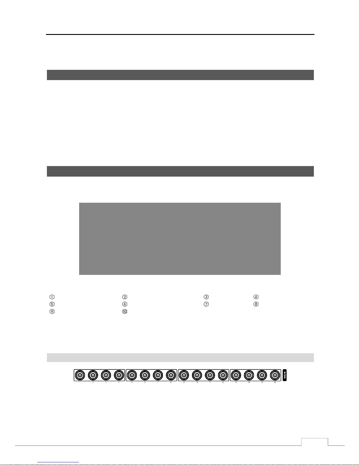
Figure 2 — 16-Channel DVR rear panel. ................................................................................................... 3
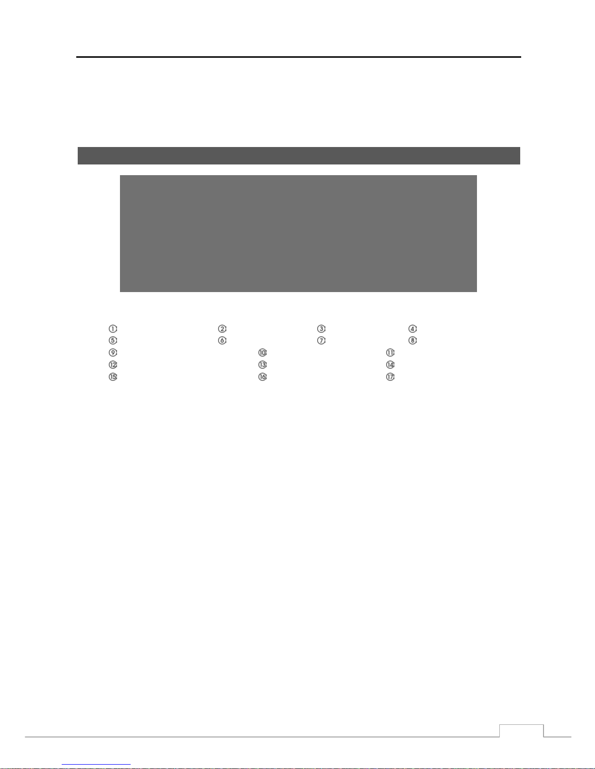
Figure 3 — 16-Channel DVR front panel. .................................................................................................. 7
Figure 4 — Infrared remote control. ........................................................................................................... 8
Figure 5 — Login screen. ......................................................................................................................... 11
Figure 6 — Logout screen. ....................................................................................................................... 11
Figure 7 — Setup screen. ........................................................................................................................ 11
Figure 8 — System menu. ....................................................................................................................... 12
Figure 9 — Information setup screen. ...................................................................................................... 12
Figure 10 — Date/Time setup screen. ..................................................................................................... 14
Figure 11 — Holiday setup screen. .......................................................................................................... 14
Figure 12 — Time Sync. screen. .............................................................................................................. 14
Figure 13 — Storage Information screen. ................................................................................................ 15
Figure 14 — Storage Status screen. ........................................................................................................ 16
Figure 15 — User setup screen. .............................................................................................................. 16
Figure 16 — Setup wizard screen. ........................................................................................................... 17
Figure 17 — Quick Setup wizard screen. ................................................................................................. 18
Figure 18 — Network Setup wizard screen. ............................................................................................. 19
Figure 19 — Shutdown screen. ................................................................................................................ 20
Figure 20 — Network menu. .................................................................................................................... 21
Figure 21 — Network setup screen. ......................................................................................................... 21
Figure 22 — LAN (Manual) setup screen. ................................................................................................ 22
Figure 23 — DVRNS setup screen. ......................................................................................................... 23
Figure 24 — RTSP setup screen. ............................................................................................................ 24
Figure 25 — WebGuard setup screen. .................................................................................................... 24
Figure 26 — Notification Callback setup screen. ..................................................................................... 25
Figure 27 — Notification Mail setup screen. ............................................................................................. 25
Figure 28 — Devices menu. ..................................................................................................................... 26
Figure 29 — Camera setup screen. ......................................................................................................... 26
Figure 30 — Camera PTZ setup screen. ................................................................................................. 27
Figure 31 — Audio setup screen. ............................................................................................................. 27
Figure 32 — Alarm-Out Settings screen. ................................................................................................. 28
Figure 33 — Alarm-Out Schedule screen. ............................................................................................... 28
Figure 34 — Display OSD screen. ........................................................................................................... 29
Figure 35 — Main Monitor screen. ........................................................................................................... 29
Figure 36 — Spot Monitor scr
een. ........................................................................................................... 30
Figure 37 — VGA screen. ........................................................................................................................ 30
Figure 38 — Remote Control setup screen. ............................................................................................. 31
Page 8

User’s Manual
vi
Figure 39 — Record menu. ...................................................................................................................... 31
Figure 40 — Record Settings screen. ...................................................................................................... 31
Figure 41 — Panic Record screen. .......................................................................................................... 32
Figure 42 — Schedule setup screen. ....................................................................................................... 33
Figure 43 — Pre-Event setup screen. ...................................................................................................... 34
Figure 44 — Event menu. ........................................................................................................................ 34
Figure 45 — Alarm-In Settings screen. .................................................................................................... 34
Figure 46 — Alarm-In Actions 1 screen. .................................................................................................. 35
Figure 47 — Alarm-In Actions 2 screen. .................................................................................................. 35
Figure 48 — Motion Detection Settings screen. ....................................................................................... 36
Figure 49 — Motion Detection Actions 1 screen. ..................................................................................... 37
Figure 50 — Motion Detection Actions 2 screen. ..................................................................................... 37
Figure 51 — Video Loss Settings screen. ................................................................................................ 38
Figure 52 — Video Loss Actions 1 screen. .............................................................................................. 38
Figure 53 — Video Loss Actions 2 screen. .............................................................................................. 38
Figure 54 — Health Check screen ........................................................................................................... 39
Figure 55 — Storage screen. ................................................................................................................... 39
Figure 56 — System Event Actions screen .............................................................................................. 40
Figure 57 — Event Status screen. ........................................................................................................... 40
Figure 58 — Live Monitoring menu. ......................................................................................................... 41
Figure 59 — PTZ Select Camera menu. .................................................................................................. 44
Figure 60 — PTZ Preset menu. ............................................................................................................... 44
Figure 61 — Sequence menu. ................................................................................................................. 45
Figure 62 — Mouse Display menu. .......................................................................................................... 46
Figure 63 — Select Playback Camera menu. .......................................................................................... 47
Figure 64 — Search menu. ...................................................................................................................... 49
Figure 65 — Event Log Search screen. ................................................................................................... 50
Figure 66 — Record Table Search screen. .............................................................................................. 52
Figure 67 — Calendar Search screen. ..................................................................................................... 53
Figure 68 — Motion Search screen. ........................................................................................................ 53
Figure 69 — Bookmarks screen. .............................................................................................................. 54
Figure 70 — Clip-Copy screen. ................................................................................................................ 55
Page 9

Digital Video Recorder
1
Chapter 1 — Introduction
Feature
Your color digital video recorder (DVR) provides recording capabilities for eight or 16 camera inputs. It provides
exceptional picture quality in both live and playback modes, and offers the following features:
8 or 16 Composite Video Input Connectors
Compatible with Color (NTSC or PAL) and B&W (CCIR and EIA-170) Video Sources
Auto Detection for NTSC and PAL
H.264 Codec
Multiple Monitor Connectors: 1 BNC Video Out, 1 Spot, 1 VGA
Multiple Search Engines (Date/Time, Calendar, Record Table, Event)
Real-time Recording (480/400 Images per Second (NTSC/PAL) with Standard (CIF) Resolution)
“Loop-Through” Video Connectors
Continuous Recording in Disk Overwrite Mode
2 USB 2.0 Ports
Continues Recording while Transmitting to Remote Site and during Playback
User-friendly Graphical User Interface (GUI) Menu System
Multiple Recording Modes (Time-lapse, Pre-event, Alarm, Motion and Panic)
Two-way Audio Communication
4-Channel Audio Recording and 1-Channel Audio Playback
Alarm Connections Include: Input, Output and Reset Input
Built-in Alarm Buzzer
Live or Recorded Video Access via Ethernet
Time Synchronization using industry standard protocol
Built-in DVD RW Drive
IR Remote Control
Self-diagnostics with automatic notification including hard disk drive S.M.A.R.T. protocol
Technical Overview
In addition to replacing both a time-lapse VCR and a multiplexer in a security installation, your DVR has many features
that make it much more powerful and easier to use than even the most advanced VCR.
The DVR converts analog NTSC or PAL video to digital images and records them on a hard disk drive. Using a hard
disk drive allows you to access recorded video almost instantaneously; there is no need to rewind tape. The technology
also allows you to view recorded video while the DVR continues recording video.
Digitally recorded video has several advantages over analog video recorded on tape. There is no need to adjust tracking.
You can freeze frames, fast forward, fast reverse, slow forward and slow reverse without image streaking or t earing .
Digital video can be indexed by time or events, and you can instantly view video after selecting the time or event.
Your DVR can be set up for event or time-lapse recording. You can define times to record, and the schedule can change
for different days of the week and user defined holidays.
The DVR can be set up to alert you when the hard disk drive is full, or it can be set to record over the oldest video once
the disk is full.
Your DVR uses a proprietary encryption scheme making it nearly impossible to alter video.
You can view video and control your DVR remotely by connecting via Ethernet. There are two USB ports that can
be used to upgrade the system or copy video clips to external hard disk and flash drives.
Page 10

User’s Manual
2
Figure 1 — Typical DVR installation.
NOTE: This manual covers the 8- and 16-channel digital video recorders. The DVRs are identical except for the
number of cameras and al arms that can be connected and the number of came ras that c an be d isplayed.
For simplicity, the illustrations and descriptions in this manual refer to the 16-camera model.
Page 11
Digital Video Recorder
3
Chapter 2 — Installation
Package Contents
The package contains the following:
Digital Video Recorder
Power Cord
User’s Manual (This Document)
RAS Software CD and User’s Manual
Rack-mount Kit
Assembly Screws and Guide Rails for Adding Hard Disk Drives
USB Mouse
Infrared Remote Control
Required Installation Tools
No special tools are required to install the DVR. Refer to the installation manuals for the other items that make up part
of your system.
Figure 2 — 16-Channel DVR rear panel.
Video Input Video Loop Through RS485 Port Alarm Input/Output
Network Port RS232C Port Audio In/Out
Video Out
Factory Reset Switch
Power Cord Connector
Your DVR can be used with either NTSC or PAL equipment.
NOTE: You cannot mix NTSC and PAL equipment. For example you cannot use a PAL camera and an NTSC
monitor.
Video Input
Connect the coaxial cables from the video sources to the BNC Video In connectors.
Page 12
User’s Manual
4
Video Loop Through
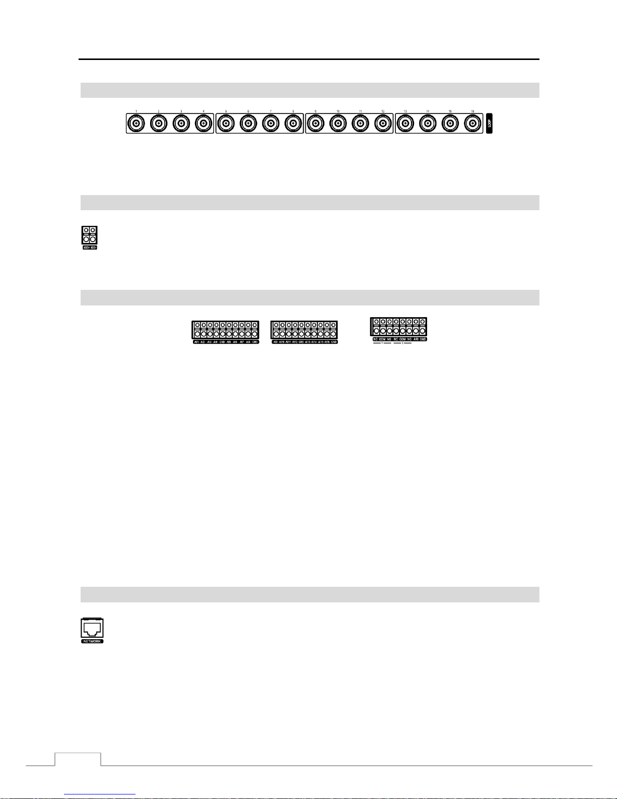
If you would like to connect your video source to another device, you can use the Loop BNC connectors.
NOTE: The Loop BNC connectors are auto terminated. Do NOT connect a cable to the Loop BNC unless it is
connected to a terminated device because it will cause poor quality video.
RS485 Port
Alarm Input/Output
NOTE: To make connections on the Alarm Conn ecto r Strip, press and hol d the button and in sert the wire in the
hole below the button. A fte r re lea s ing the button, tug gently on th e wire to make certain it is connected.
To disconnect a wire, press and hold the button above the wire and pull out the wire.
AI 1 to 16 (Alarm-In): You can use external devices to signal the DVR to react to events. Mechanical or electrical
switches can be wired to the AI (Alarm-In) and GND (Ground) connectors. The threshold voltage of electrical switches
for NC (Normally Closed) is above 2.4V and for NO (Normally Open) is below 0 .3V, and should be stable at least 0.5
seconds to be detected. The voltage range of alarm input is from 0V to 5V. See Chapter 3 ─ Configuration for
configuring alarm input.
GND (Ground): Connect the ground side of the Alarm input and/or alarm output to the GND connector.
NOTE: All the connectors marked GND are common.
NC/NO (Relay Alarm Outputs): The DVR can activate external devices such as buzzers or lights. Connect the device
to the C (Common) and NC (Normally Closed) or C and NO (Normally Open) con nectors. NC/NO is a relay output
which sinks 2A@125VAC and 1A@30VDC. See Chapter 3 ─ Configuration for configuring alarm output.
ARI (Alarm Reset In): An external signal to the Alarm Reset In can be used to reset both the Alarm Out signal and the
DVR’s internal buzzer. Mechanical or electrical switches can be wired to the ARI (Alarm Reset In) and GND (Ground)
connectors. The threshold voltage is below 0.3V and should be stable at least 0.5 seconds to be detected. Connect the
wires to the ARI (Alarm Reset In) and GND (Ground) connectors.
Network Port
CAUTION: The network connector is not desig ned to be connected directly with cable or wire
intended for outdoor use.
The DVR can be controlled remotely by an external device or control system, such as a control keyboard,
using RS485 half-duplex serial communications signals. The RS485 connector can also be used to control
PTZ (pan, tilt, zoom) cameras. Connect RX+/TX+ and RX-/TX- of the control system to the + and –
(respectively) of the DVR. See Chapter 3 ─ Configuration and the PTZ camera or remote controller
manufacture’s manual for configuring the RS485 connection.
The DVR can be networked using the 10/100Mb Ethernet connector. Connect a Cat5 cable with an RJ-45
jack to the DVR connector . The DVR can be netwo rked with a comput er for remote monito ring, searchin g,
configuration and software upgrades. See Chapter 3 ─ Configuration for configuring the Ethernet
connections.
Page 13

Digital Video Recorder
5
RS232C Port
Audio In/Out
NOTE: It is the user’s responsibility to determine if local laws and regulations permit recording audio.
The DVR does not have amplified audio output, so you will need a speaker with an amplifier. The DVR
does not have a pre-amplifier for audio input, so the audio input should be from an amplified source,
not directly from a microphone.
Video Out
NOTE: The VGA and Video Out (BNC) connectors may be connected to individual monitors for simultaneous
operation.
Factory Reset Switch
The DVR has a Factory Reset switch to the left of the VGA connector on the rear panel.
This switch will only be used on the rare occasions that you want to return all the settings
to the original factory settings.
CAUTION: When using the Factory Reset, you will lose any settings you have saved.
To reset the unit, you will need a straightened paperclip:
1. Turn the DVR off.
2. Turn it on again.
3. While the DVR is initializing, the front panel LEDs will blink. When the front panel LEDs blink, poke the
straightened paperclip to the unlabeled hole in the left of the VGA connector.
4. Hold the switch until all the LEDs on the front panel are lit.
NOTE: When the DVR success fully resets to factory defaults all the LEDs on the front panel flash five times.
5. Release the reset switch. All of the DVR’s settings are now at the original settings it had when it left the factory.
Power Cord Connector
An RS232 port is provided to connect a remote control keyboard.
Your DVR can record audio from up to four sources. Connect the audio sources to
Audio In 1, Audio In 2, Audio In 3 and Audio In 4 as needed using RCA jacks.
Connect Audio Out to your amplifier.
A VGA connector is provided so that you can use a standard, multi-sync computer monitor
as your main monitor. Use the cable supplied with your monitor to connect it to the DVR.
Connect the main monitor to the Video Out connector. Connect the spot monitor to the
SPOT connector as needed.
Connect the AC power cord to the DVR and then to a wall outlet.
Page 14

User’s Manual
6
WARNING: ROUTE POWER CORDS SO THAT THEY ARE NOT A TRIPPING HAZARD. MAKE
CERTAIN THE POWER CORD WILL NOT BE PINCHED OR ABRADED BY FURNITURE.
DO NOT INSTALL POWER CORDS UNDER RUGS OR CARPET.
THE POWER CORD HAS A GROUNDING PIN. IF YOUR POWER OUTLET DOES NOT
HAVE A GROUNDING PIN RECEPTACLE, DO NOT MODIFY THE PLUG. DO NOT
OVERLOAD THE CIRCUIT BY PLUGGING TOO MANY DEVICES IN TO ONE CIRCUIT.
Your DVR is now ready to operate. Refer to Chapter 3 ─ Configuration and Chapter 4 ─ Operation.
Page 15
Digital Video Recorder
7
Chapter 3 — Configuration
NOTE: Your DVR should be completely installed before proceeding. Refer to Chapter 2 — Installation.
Front Panel Controls
Figure 3 — 16-Channel DVR front panel.
Camera Buttons Power LED HDD LED Alarm Out LED
Network LED Clip Copy LED Panic Button Alarm Button
Clip Copy Button Zoom/PTZ Button Display/SPOT Button
Group/Sequence Button Playback Button Menu/Cameo Button
Arrow Buttons Play/Pause Button USB Connector
The front panel looks and operates much like a VCR combined with a multiplexer. Many of the buttons have multiple
functions. The buttons on the infrared remote cont rol, while laid out differen tly, perform the same functions as those
on the front panel. The following describes each button and contro l. Take a f ew minutes to r eview the descrip tions.
You will use these to initially set up your DVR and for daily operations.
NOTE: The infrared sensor on the DVR is just to the right of the camera buttons. Make certain that nothing blocks
the sensor, or the remote control will not function properly.
When you use wireless communication devices (such as Wi-Fi or Bluetooth) near the DVR, the remote
control might not function properly.
You can also use a USB mouse to navigate through the screens and menus much like you would on a
computer.
Page 16
User’s Manual
8
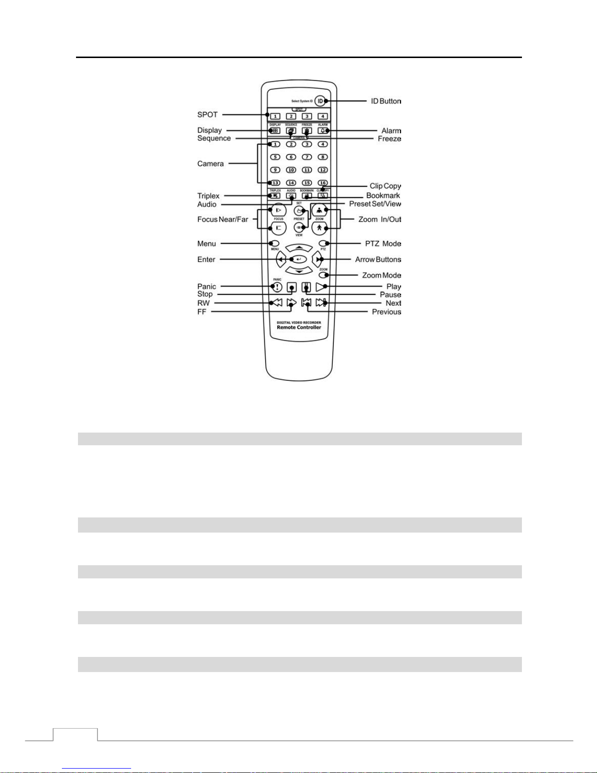
Figure 4 — Infrared remote control.
NOTE: For simplicity, the button descriptions in this manual refer to the front panel buttons.
Camera Buttons (1 to 16)
Pressing the individual camera buttons will cause the selected camera to display full screen. Buttons 1 to 9 are also
used to enter passwords.
In the PTZ mode, pressing the button 1 zooms in the screen and the button 2 zooms out the screen, pressing the button
3 focuses near and button 4 focuses far, and pressing the button 5 moves to the preset and button 6 saves the preset.
Power LED
The Power LED is lit when the unit is On.
HDD LED
The HDD LED flickers when the DVR is recording or searching video on the hard disk drive.
Alarm Out LED
The Alarm Out LED is lit when alarm output or internal buzzer is activated.
Network LED
The Network LED is lit when the unit is connected to a network via Ethernet.
Page 17
Digital Video Recorder
9
Clip Copy LED
The Clip Copy LED is lit when the DVR is clip-copying.
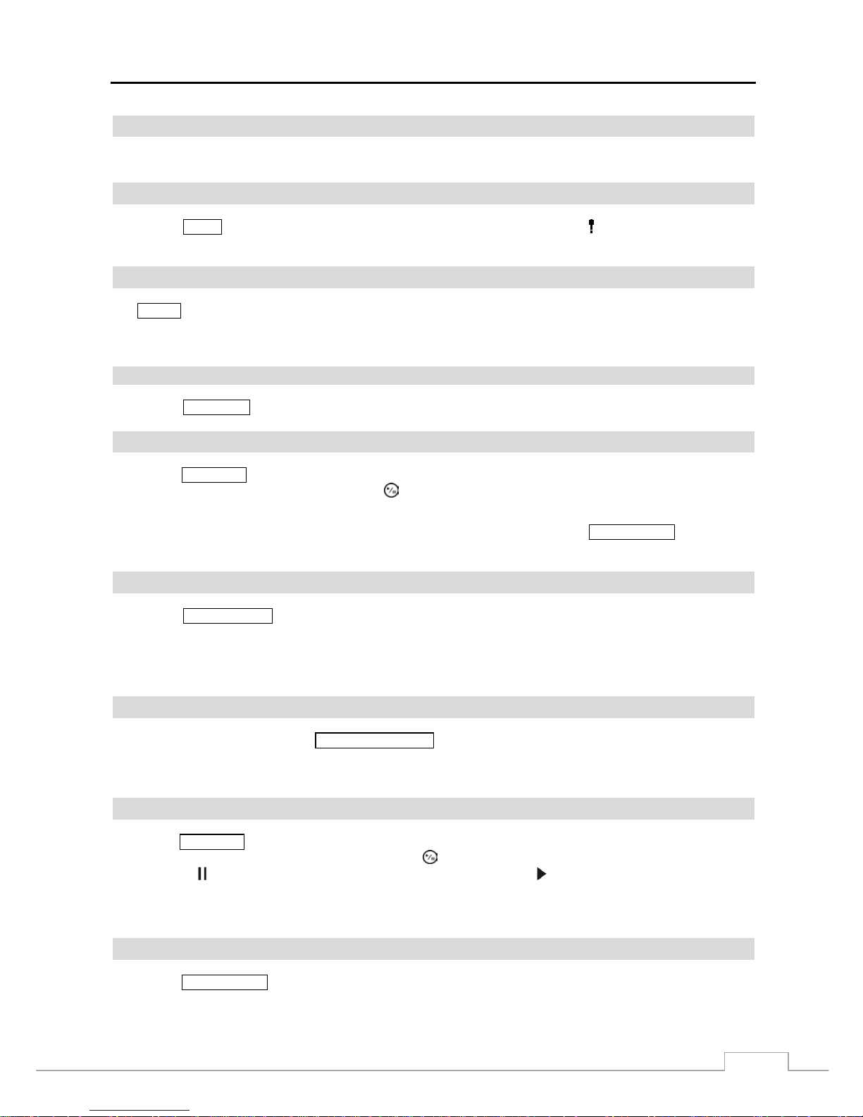
PANIC Button
Pressing the PANIC button starts panic recoding of all camera channels, and displays on the screen. Pressing the
button again will stop panic recording.
ALARM Button
The ALARM button has two functions. First, it will reset the DVR’s outputs including the internal buzzer during an
alarm. Second, it will display the event log when you are in the live monitoring mode unless there is an active alarm.
This operation can be user password protected.
CLIP COPY Button
Pressing the CLIP COPY button allows you to copy video clips.
ZOOM/PTZ Button
Pressing the ZOOM/PTZ button zooms in the current image in double on the screen. You can use the arrow buttons to
move the rectangle to another area. Pressing the (Play/Pause) button zooms in the image in rectangle.
Pressing and holding the button for three seconds or longer enters the PTZ (Pan/Tilt/Zoom) mode and the PTZ icon
flickers. Pressing the button again exits the PTZ mode. Pressing the arrow buttons or
MENU/CAMEO button allows
you to control properly configured cameras.
DISPLAY/SPOT Button
Pressing the DISPLAY/SPOT button toggles between different display formats. The available formats are: PIP, 2x2,
1+5, 1+7, 3x3 and 4x4.
Pressing and holding the button for three seconds or longer allows you to select which cameras will display on the
Spot monitor.
GROUP/SEQUENCE Button
When in the live mode, pressing the GROUP/SEQUENCE button changes the screen from the current camera group
to the next camera group, and the screen displays the page number. Pressing and holding the bu tton for three seconds
or longer displays live channels sequentially.
PLAYBACK Button
Pressing th e PLAYBACK button enters the playback mode, and pressing the button again exits the playback mode. When
entering the playback mode, video is paused. Pressing the (Play/Pause) button plays back video at regular speed. The
screen displays
when the DVR is in the Pause mode and the screen displays when the DVR is playing back video.
When in one of the multi-view formats, pressing this button enters the Tr iplex m ode. The DVR supports the Triplex
function: monitoring, recording and playing back at the same time.
MENU/CAMEO Button
Pressing the MENU/CAMEO button enters the Setup screen. You will need to enter the authorized user and password
to access Setup. Pressing the button also closes the current menu or setup dialog box. In the Playback mode, pressing
the button displays the Search menu.
Page 18
User’s Manual
10
Pressing and holding the button for three seconds or longer enters the cameo mode. The yellow outline surrounding the
video indicates the active cameo, and pressing the arrow buttons moves the active cameo. Pressing the desired camera
button in the active cameo edits the cameo and displays the video of selected camera. Pressing the
(Play/Pause)
button exits the Active Cameo mode. Selecting Exit Group Edit in the cameo menu displayed when pressing the
MENU/CAMEO button also exits the Active Cameo mode.
NOTE: A cameo is defined a s any cell within multi-scre en d isplay. The cameo mode allows you to change the
screen layout by editing the cameo.
Arrow Buttons
These buttons are used to navigate through menus and GUI. You can also use them to change numbers by highlighting
a number in the menu and using the Up and Down arrow buttons to increase or decrease the number’s value.
These buttons are also used to control Pan and Til t when in the PTZ mode. When in the PIP display format, pr essing
the Up and Down arrow buttons moves the position of the small screen counter-clockwise and clockwise, and pressing
the Left and Right buttons changes the PIP screen size.
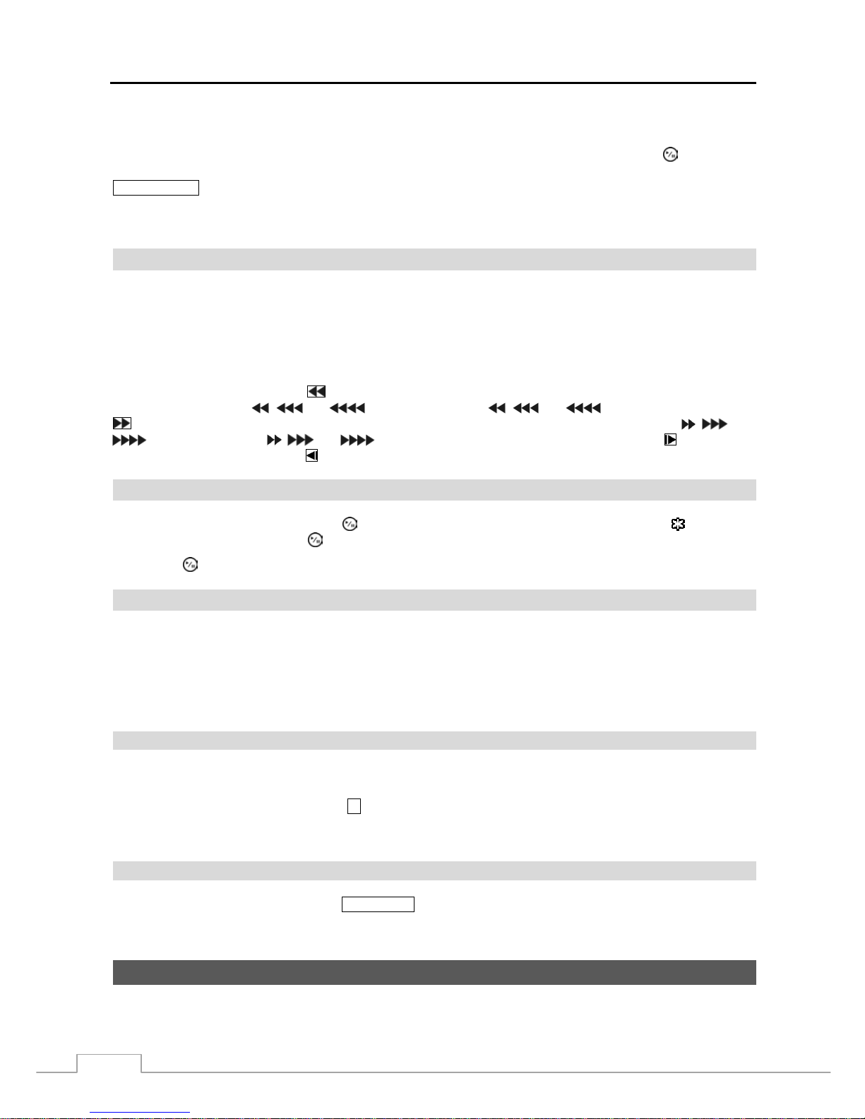
In the playback mode, pressing the button plays video backward at high speed. Pressing the button again toggles
the playback speed from
, and . The screen displays , and respectively. Pressing the
button plays video forward at high speed. Pressing the button again toggles the playback speed from , and
. The screen displays , and
respectively. When in the pause mode, pressing the
button moves
to the next image and pressing the
button moves to the previous image.
PLAY/PAUSE Button
In the live monitoring mode, pressing the button freezes the current screen and the screen displa ys
icon. When
in the playback mode, pressing the
button plays back images at regular speed or pauses playing video.
Pressing the button selects a highlighted item or completes an entry that you have made during system setup.
USB Port
Two USB ports on the front panel are provided to connect external hard disk or flash drives for video clip copying or
system upgrades. Position external drives close enough to the DVR so that you can make the cable connections, usually
less than 6 feet. Use the USB cable provided with the hard disk drive to connect it to the DVR.
A USB mouse can be connected to one of the ports. You can use the mouse to navigate through the screens and menus
much like you would on a computer.
ID Button on Remote Control
If a DVR System ID is set to 0, the infrared remote control will control that DVR without any additional operations.
(Refer to the System Information setup screen in this chapter for further inform ation on sett ing the S ystem ID.) If the
system ID is 1 to 16, you must to press the
ID button on the remote control and then press the number button (1 to 16)
in order to control that DVR. If the S ystem ID of two or more DVRs is set to 0, tho se DVRs will react to the infrared
remote control at the same time.
Bookmark Button on Remote Control
When in the playback mode, pressing the
BOOKMARK button adds the current playback point to the bookmark list or
moves to the registered bookmark point.
Turning on the Power
Connecting the power cord to the DVR turns on the unit. The unit takes approximately 60 seconds to initialize.
Page 19
Digital Video Recorder
11
Initial Unit Setup
Before using your DVR for the first time, you will want to establish the initial settings. This includes items such as
time and date, display language, camera, remote c ontrol, record m ode, network and password. Your DVR can be set
up using various screens and dialog boxes.
Throughout the screens you will see
. Highlighting the and pressing the button gives you the opportunity to
reset that screen to its default settings. After you are finished with any setup screen, you can highlight Save and press
the
button to save the changes and exit the screen. If you do not wish to save the changes, highlight Cancel and
press the
button to exit the screen.
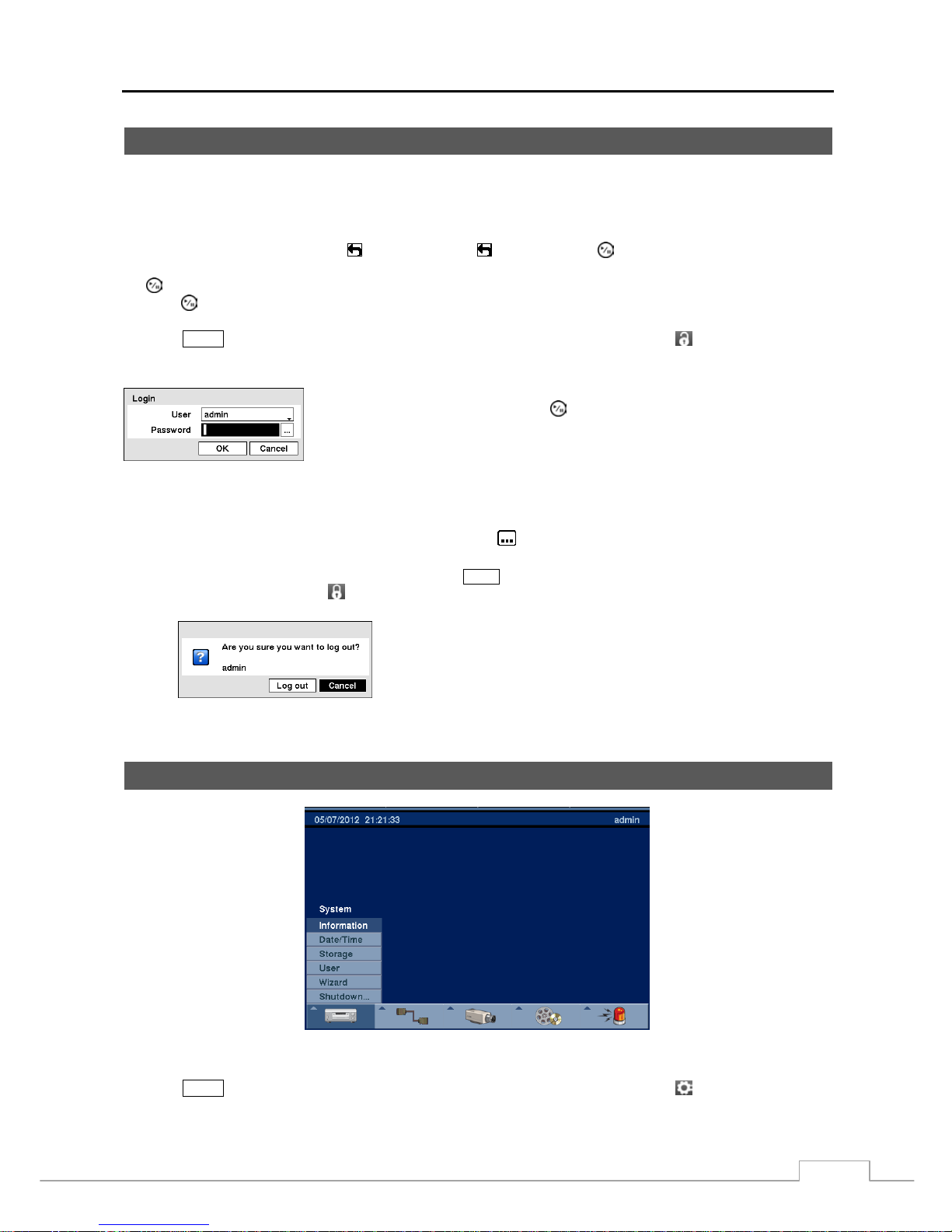
Press the
MENU button or move the mouse pointer to the top of the screen and then select (Login) in the Live
Monitoring menu to enter the setup screens. The Login screen appears.
Select a User and enter the password by pressing the appropriate combination of
Camera number buttons and then the
button. There is no default password when
logging in the admin user for the first time.
Figure 5 — Login screen.
NOTE: To assure the secure management of the system, setting up a password is strongly recommended.
If you cannot use the fron t p an el but tons, click the
button using the mouse to enter a pass word, and
the virtual keyboard displays. See instructions below for using the virtual keyboard.
To log the user out of the system, press the
MENU button or move the mouse pointer to the top of the
screen and then select (Logout) in the Live Monitoring menu. The Logout screen displays asking
you to confirm whether or not you want to log out the current user.
Figure 6 — Logout screen.
Setup Screen
Figure 7 — Setup screen.
Press the
MENU button or move the mouse pointer to the top of the screen and then select (Setup) in the Live
Monitoring menu to enter the setup screen.
Page 20
User’s Manual
12
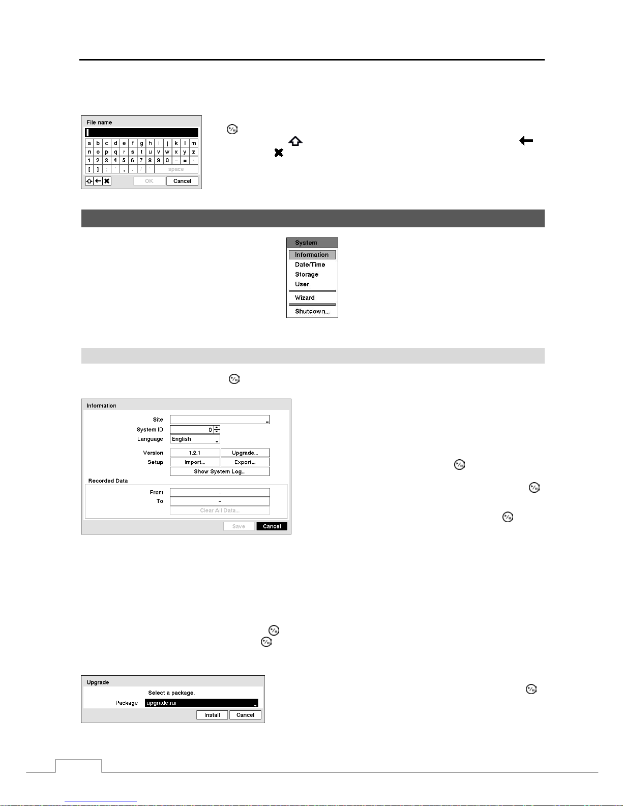
While setting up the DVR, there will be many opportuniti es to enter names and titles. When making these entries, a
Virtual Keyboard will appear.
Use the arrow keys to highlight th e character you want in the name or title and press
the
button. That character appears in the title bar and the cursor moves to the next
position. Pressing
toggles between the upper and lower case keyboards,
backspaces, and
deletes entered characters. You can use up to 31 characters inclu ding
spaces in your title.
System Setup
Figure 8 — System menu.
Information
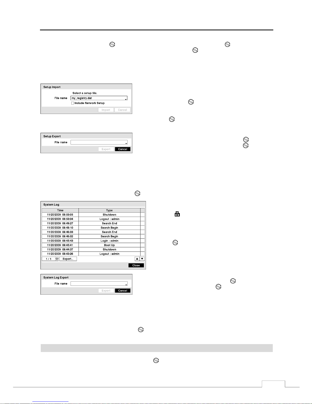
Highlight Information and press the button. The Information screen appears.
Figure 9 — Information setup screen
.
In the Information screen, you can name the site location,
assign a System ID number, select the language the screens
are displayed in, display software version number, upgrade
the software, show the System Log, display recorded time
data, and clear all data.
Highlight the Site box and press the button. A virtual
keyboard appears that you can use to enter a Site Name. Once
you have entered your title, highlight OK and press the
button.
Highlight the box beside System ID and press the button.
Change the number by highlighting it and using the Up and
Down arrow buttons to increase and decrease the number
from 0 to 99.
NOTE: The System ID number is used to identify the unit when it is connected with other DVRs through the
RS485 port. You cannot use the same ID number for two or mo re DVRs that are in the same RS485
network. It is possible to have multiple DVRs with System ID 0 that are in the same area as long as they
are not part of an RS485 network. If this is the case, all will be controlled at the same time when using
the infrared remote control.
Highlight the box beside Language and press
button. A drop-down menu displays the available languages.
Highlight the desired language and press the
button.
The box beside Version displays the software version of the DVR.
To upgrade the software, connect a USB device containing the upgrade
package file to the DVR. Highlight Upgrade… and press the
button. The Upgrade screen appears. The screen displays the upgrade
package file names that are available. The “.rui” indicates that the file
is for software upgrades and “.ofi” indicates that the file is for optical
drive firmware upgrades.
Page 21
Digital Video Recorder
13
Select the desired file and press the
button. Highlighting the Install button and pressing the button will install the
selected software package. Highlighting the Cancel button and pressing the
button will close the window without
upgrading the software. If the upgrade package file is not installed on the DVR properly, you will get an error message.
The system restarts automatically after completing the upgrade.
CAUTION: The USB device must be FAT16 or FAT32 format.
You can import saved DVR settings or export the current DVR
settings. To import saved DVR settings, connect the USB device
containing the setup file (.dat) to the DVR. Highlight Setup –
Import… and press the
button. Select the desired setup file and
press the Import button to import the selected settings and change
the DVR settings accordingly. Highlight Include Network Setup
and press the
button to toggle between On and Off. When set
to Off, the network settings will not be changed.
To export the current DVR settings, connect the USB device to the
DVR. Highlight Setup – Export… and press the
button.
Highlight the box beside File name and press the
button. A
virtual keyboard allows you to enter the file name. Selecting Export
will save the current settings in .dat file format on the USB device.
NOTE: Even after changing th e D VR s et tin gs by importing saved setting s, th e ti me- r el at ed s ett ings (Date/Time,
Time Zone and Daylight Saving Time) will NOT be changed.
CAUTION: The USB device must be FAT16 or FAT32 format.
Highlight Show System Log… and press the
button to display the System Log.
The System Log screen lists system activities (up to 5,000
from the latest) that have occurred along with the time and
date. The
icon will be displayed in the last column for
system activities of the remote site. You can scro ll through
the log pages by using the Up and Down arrows, or you can
go directly to a log page by entering the log page number in
the box at the bottom left of the screen. Highlight Close and
press the button to exit the screen.
To export the system log information, connect the USB device to
the DVR. Highlight Export… and press the button. Highlight
the box beside File name and press the button. A virtual keyboard
allows you to enter the file name. Selecting Export will save the
log information in .txt file format on the USB device.
NOTE: When opening the saved .txt file, setting to the proper character encoding and using fixed width fonts
will be required to read the file properly.
The box beside Recorded Data – From / To displays the time information of recorded data.
Highlighting Clear All Data… and pressing the button will clear all video data. You will be asked to verify that
you wish to clear all data before the DVR erases the video data. Clear All Data… will not clear the System Log.
Date/Time
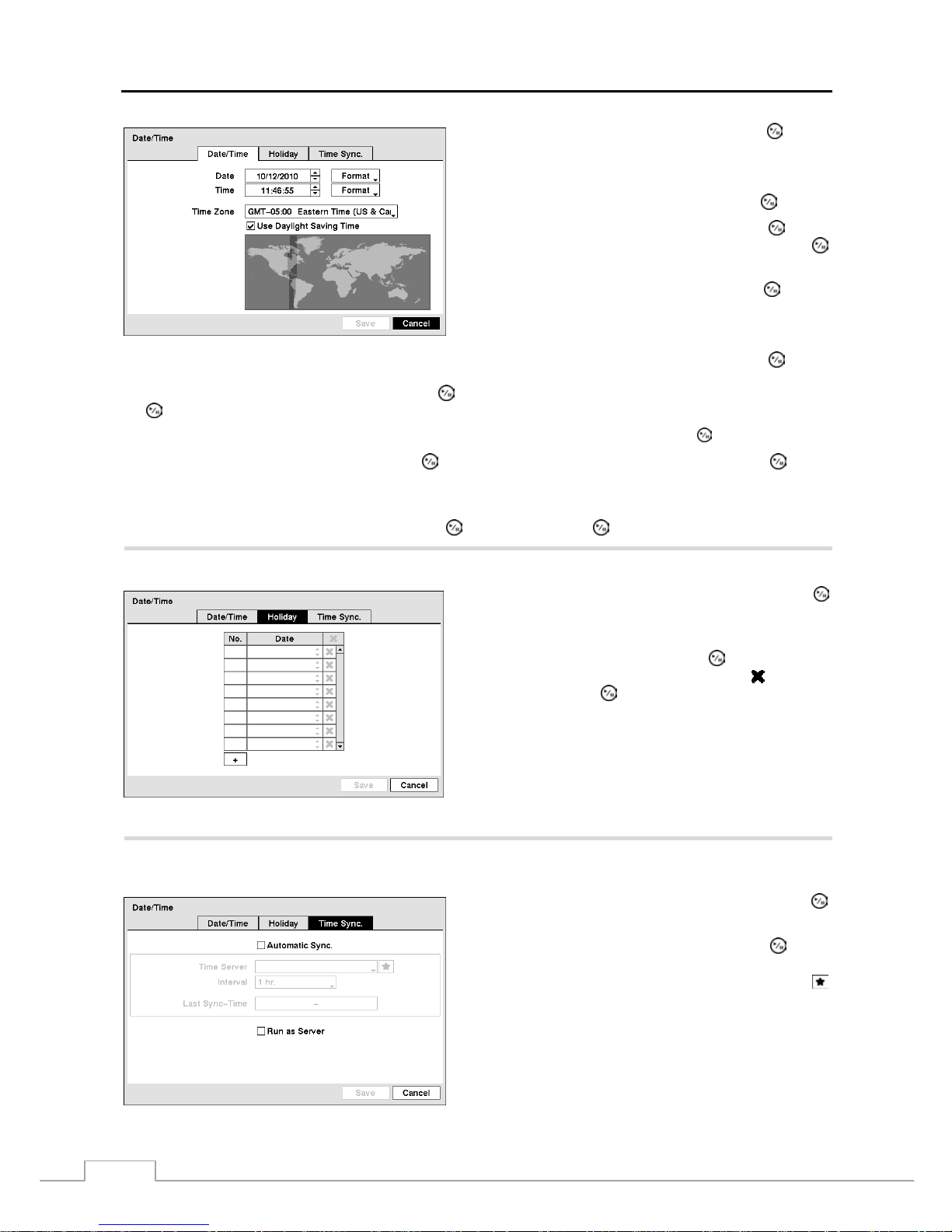
Highlight Date/Time in the System menu and press the
button. The Date/Time setup screen appears.
Page 22
User’s Manual
14
Figure 10 — Date/Time setup screen.
Highlight the first box beside Date and press the
button.
The individual sections of the date will highlight. Use the Up
and Down arrow buttons to change the number. Use the Left
and Right arrow buttons to move between month, date and
year. Once you have the correct date, press the
button.
Highlight the Format box beside Date and press the button.
Select from the three available date formats and press the
button to save your selected format.
Highlight the first box beside Time and press the button.
The individual sections of the time will highlight. Use the Up
and Down arrow buttons to change the number. Use the Left
and Right arrow buttons to move between hour, minutes and
seconds. Once you have the correct time, press the
button.
Highlight the Format box beside Time and press the button. Select from the three available time formats and press
the
button to save your selected format.
NOTE:
The clock will not start running until you have highlighted Save and pressed the
button.
Highlight the box beside Time Zone and press the button. Select your time zone from the list and press the button.
NOTE: The Time Zone can also be selected on the map below by pressing the Left and Right buttons o r scrolling
the mouse wheel up and down.
Highlight Use Daylight Saving Time and press the button. Pressing the button toggles between On and Off.
Highlight the Holiday tab, and the Holiday setup screen appears.
You can set up holidays by highlighting + and pressing the
button. The current date appears.
Highlight the month and day and change them by using the
Up and Down arrow buttons. Press th e button to add the
date. Dates can be deleted by highlighting the
beside the
date and pressing the
button.
NOTE: Holidays that do not fall on the same date each
year should be updated once the current year’s
holiday has passed.
Figure 11 — Holiday setup screen.
Highlighting the nc. tab causes the Time Sync. screen to display. You can set up time synchronization between the DVR
and standard time servers that are available in most time zones and countries, or between the DVR and another DVR.
Figure 12 — Time Sync. screen.
Highlight the box beside Automatic Sync. and press the
button. This toggles between On and Off.
Highlight the box beside Time Server and press the button.
A virtual keyboard appears that you can use to enter the IP
address or domain name of the time server. Highlighting
allows you to select your time server from a list of registered
time servers.
NOTE: You can use the domain name i nstead of IP address
if you already set up the DNS Server when sett ing
up the LAN.
Page 23
Digital Video Recorder
15
Highlight the box beside Interval and press the
button. Set the time interval for synchronization from 30 minutes
to 1 day at various time intervals.
Last Sync-Time displays the last time the DVR was synchronized with the time server.
Highlight Run as Server and press the button. Pressing the button toggles between On and Off. When it is
On, the DVR you are setting up will run as a time server.
Storage
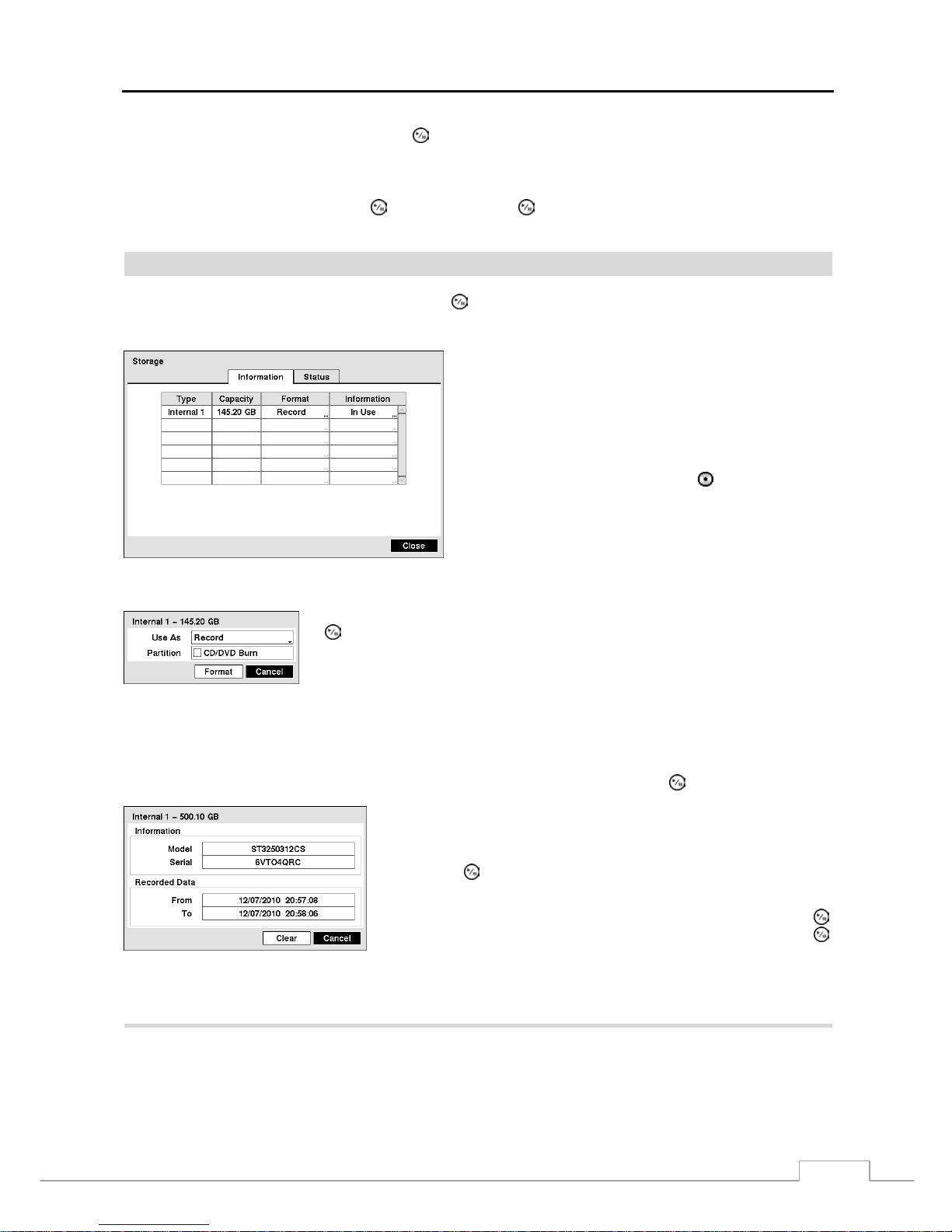
Highlight Storage in the System menu and press the
button. The Storage setup screen appears and displays
information about the DVR’s storage devices.
The information in the Type column describes the storage
device.
The capacity of the storage d evice is displa yed in the Capacity
column.
The Format column displays whether the device is used for
recording (Record) or not (Not Using). Not formatted
indicates the device is not formatted. indicates when the
device has temporary space set aside so that video clips can
be saved on a DVD RW.
Figure 13 — Storage Information screen.
Highlight the box in the Format column for the desired storage device and pr ess the
button. You will be able to format the device for recording . When selecting Not
Using from Use As and highlighting the Format button, the device will not be used
for recording. You can also set aside spac e to store t emporary fi les for CD or DVD
burning by selecting Partition – CD/DVD Burn.
NOTE: The DVR does NOT support USB hard disk drives with a version lower than 2.0.
The Information column displays whether the device is being used or not. Other indicates the devic e has been us ed
for another DVR.
Highlight the box in the Information column for the desired storage device and press the
button.
You will be able to check the model name, serial number and the time
information about recorded data of the selected storage device.
If you want to erase recorded data on th e selected device, highlight Clear
and press the button. You will be asked whether or not you want to delete
the data.
If you want to use a USB hard disk drive, highlight Use and press the
button after connecting the device. Highlight Don’t Use and press the
button if you want to stop using the device.
CAUTION: Do NOT disconnect the USB cable or the power from the device while copying video clips.
If the USB cable is disconnected while copying video clips, archived data might be lost.
Highlight the Status tab, and the Storage Status screen displays.
Page 24
User’s Manual
16
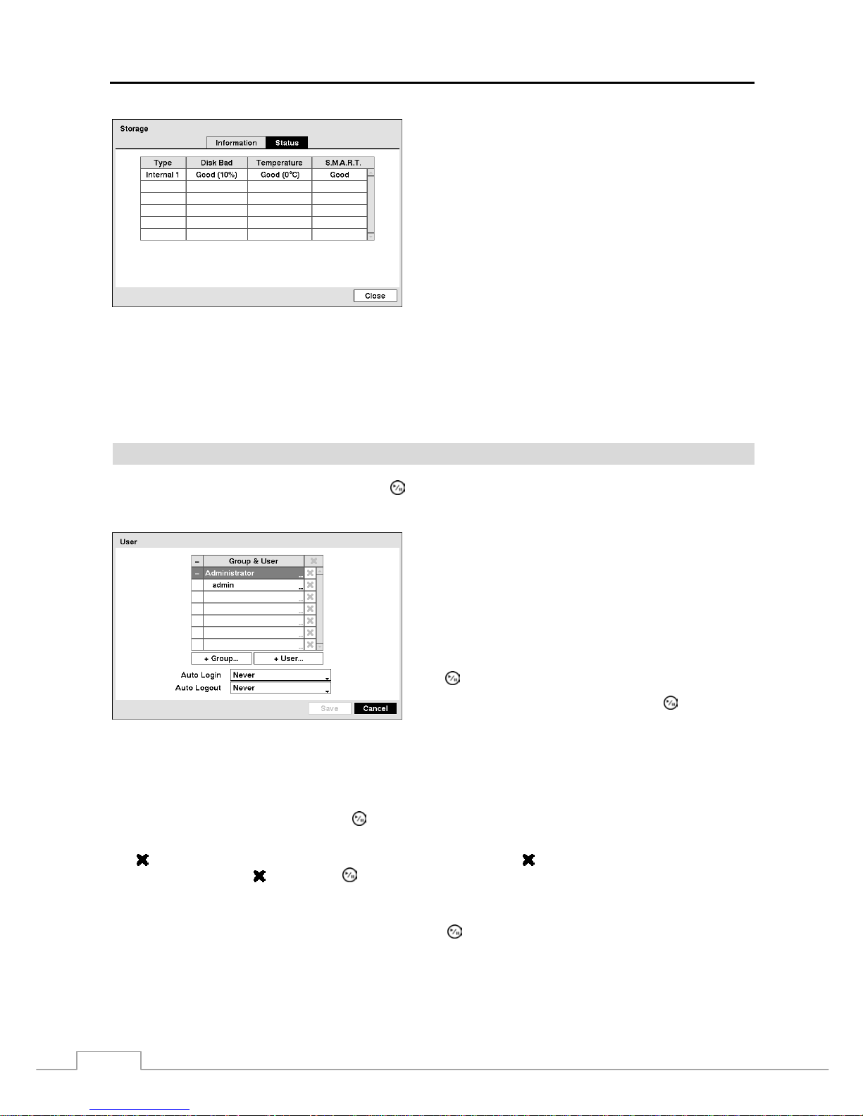
Figure 14 — Storage Status screen.
The Type column displays the type of storage device.
The Disk Bad column displays the percentage of bad sectors.
Not formatted indicates the device is not formatted.
The Temperature column displays the temperature of the
storage device.
The S.M.A.R.T. column displays “Good”, “Bad” or “N/A”,
depending on storage conditions.
Good – The storage condition is normal.
Bad – Data cannot be written on or read from the storage device.
N/A – Storage conditions are normal, however, the S.M.A.R.T.
monitoring is not working or supported.
NOTE: When the storage condition is “Bad”, the Event Status – Storage screen displays and you can check
the storage condition for details. Once the “Bad” message displays, replacing the hard disk drive is
recommended, usually within 24 hours.
Temperature and S.M.A.R.T. information will be available only for internal hard disk drives supporting
the SMART (Self-Monitoring Analysis and Reporting Technology) monitoring program.
User
Highlight User in the System menu and press the
button. The User setup screen displays the authorized groups
and users. You can add and delete groups and users. When adding a group, you can assign authority levels to the group.
Figure 15 — User setup screen.
The +/- column is used to collaps e and exp and user groups.
If there is a + or – in this column, it indicates the item is a
Group Name. If there is a – in front of the Group Name, it
indicates that the group has been “expanded” and all of the
User Names within that group are displayed below the Group
Name. If there is a + in front of the Group Name, it indicates
that the group has been “collapsed” and all of the User Names
within that group are hidden. To collapse or expand a group,
highlight the +/- column in front of the desired group and press
the
button.
Highlighting a Group Name and p ressing th e
button allows
you to change the authority levels assigned to the group.
CAUTION: Write down the new password and save it in a secure place. If the password is forgotten,
the unit must be reset using the Factory Reset Button and all data settings will be lost.
Highlighting a User Name and pressing the
button allows you to add or change the password assigned to that user.
You can also change the group to which the user is assigned.
The column can be used to delete a User Name or an entire Group. If the is grayed out, that Group or User cannot
be deleted. Highlight the
and press the
button. You will be asked to confirm that you want to d elete the User or
Group. To delete the User currently logged into the DVR on a lo cal system or a PC running RAS, log th e user out of
the system first and then delete the user.
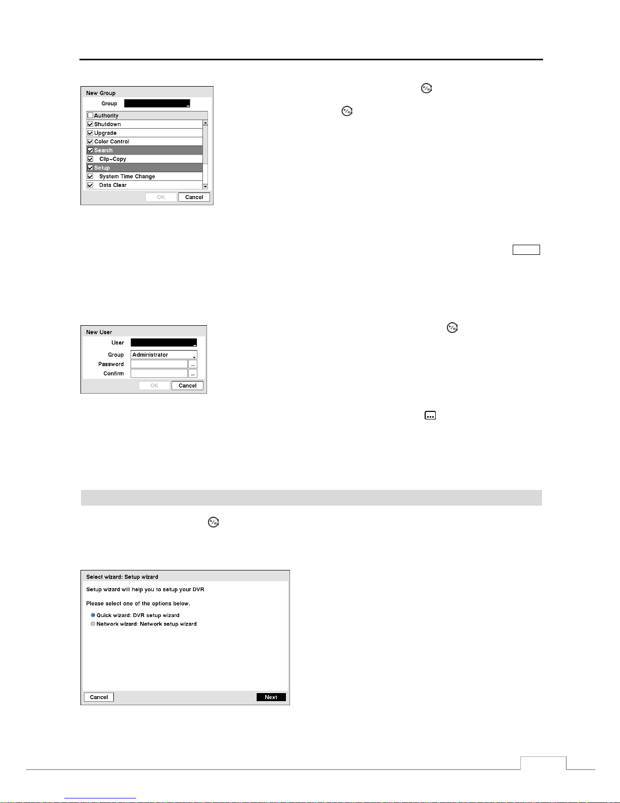
To add a Group, highlight the + Group… box and press the
button. A virtual keyboard appears allowing you to
enter the Group name. You can use up to 15 characters including spaces in the group name. Enter the name and assign
authority levels to the group.
Page 25
Digital Video Recorder
17
Highlighting the Authority box and pressing the
button will toggle between
all authority levels being turned On and Off. Highlighting the individual authority
level boxes and pressing the
button will toggle between that authority level
being turned On and Off. The authority levels that can be turned On and Off are:
Shutdown – The user can shut the system down on a local system.
Upgrade – The user can upgrade the software on a local system or a PC running RAS.
Color Control – The user can control brightness, contrast, hue and saturation for
cameras on a local system or a PC running RAS.
Search – The user can access the Se arch mode on a local sy stem or a PC runni ng RAS.
Clip-Copy – The user can copy video clips on a local system or a PC running RAS.
Setup – The user without Setup author ity cannot esta blish any sy stem sett ings excludin g
system shutdown and logout on a local system or a PC running RAS
System Time Change – The user can change the system date and time on a local system or a PC running RAS.
Data Clear – The user can clear all video data or format disks on a local system or a PC running RAS.
PTZ Control – The user can control the PTZ camera on a local system or a PC running RAS.
Alarm-Out Control – The user can reset the DVR’s outputs including the internal buzzer during an alarm by pressing the
ALARM
button on a local system or alarm-out control button on a PC running RAS.
Covert Camera View – The user can view video from cameras set as Covert while in the Live Monitoring or Search mode on
a local system or a PC running RAS.
System Check – The user can view the remote system status or check the remote system status as a batch process on a PC running
RAS.
Record Setup – The user can establish all Record settings on a local system or a PC running RAS.
To add a User, highlight the + User… box and press the
button. A virtual
keyboard appears allowing you to enter the User Name. Enter the name and assign
the User to a Group and password. You can use camera buttons 1 to 9 on the front
panel to assign the password. The password can be up to 8 digits. You will be asked
to confirm the password.
NOTE: In addition to using the front panel buttons or the infrared remote control, you can use the virtual
keyboard to assign the pa ssword. To display the virtual key board c li ck t he
button using the mouse.
Highlighting the box beside Auto Login allows you to select a User to be automatically logged in when the DVR is
powered up. It can also be set to never automatically login a user.
Highlighting the box beside Auto Logout allows you to select fro m a list of t imes that the user will be au tom aticall y
logged out. The options are: Never, 1 min., 3 min., 5 min., 10 min., 15 min., 20 min., 30 min. and 1 hr.
Wizard
Highlight Wizard and press the button. The Wizard setup screen appears. The Wizard setup guides you through
configuring the system for basic operation.
NOTE: This Wizard screen can only be accessed when logged on as the admin user.
Figure 16 — Setup wizard screen.
Select either Quick wizard or Network wizard and select
the Next button to start the selected setup wizard.
NOTE: Selecting the Cancel button throughout the screens
exits the Quick Setup Wizard without saving your
changes and returns to the main setup screen.
Page 26
User’s Manual
18
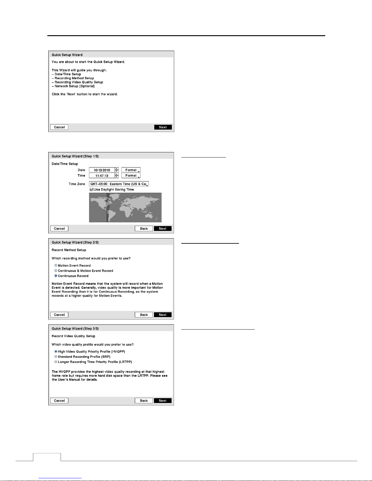
Figure 17 — Quick Setup wizard screen.
If you selected the Quick wizard, selecting the Next button
starts the Quick Setup Wizard.
Date/Time Setup
Date: Set the system date and select the date format.
Time: Set the system time and select the time format.
Time Zone: Select your time zone. The Time Zone can be
selected on the map.
Use Daylight Saving Time: Selecting the box sets the
system to use daylight saving time.
NOTE: The Date/Time will be set, and the clock will start
when you click the Next button.
Record Method Setup
Select the desired recording mode from:
– Motion Event Record
– Continuous & Motion Event Record
– Continuous Record
NOTE: You should understand each recording mode before
setting the DVR’s recording method.
Record Video Quality Setup
Select the desired video quality profile from:
– Higher Video Quality Priority Profile
– Standard Recording Profile
– Longer Recording Time Priority Profile
NOTE: The higher quality setting requires more storage
space.
NOTE: The recording resolution will be set to Very High
when selecting High Video Quality Priority Profile,
High when selecting Standard Recording Profi le,
and Standard when selecting Longer Recording
Time Priority Profile.
Page 27
Digital Video Recorder
19
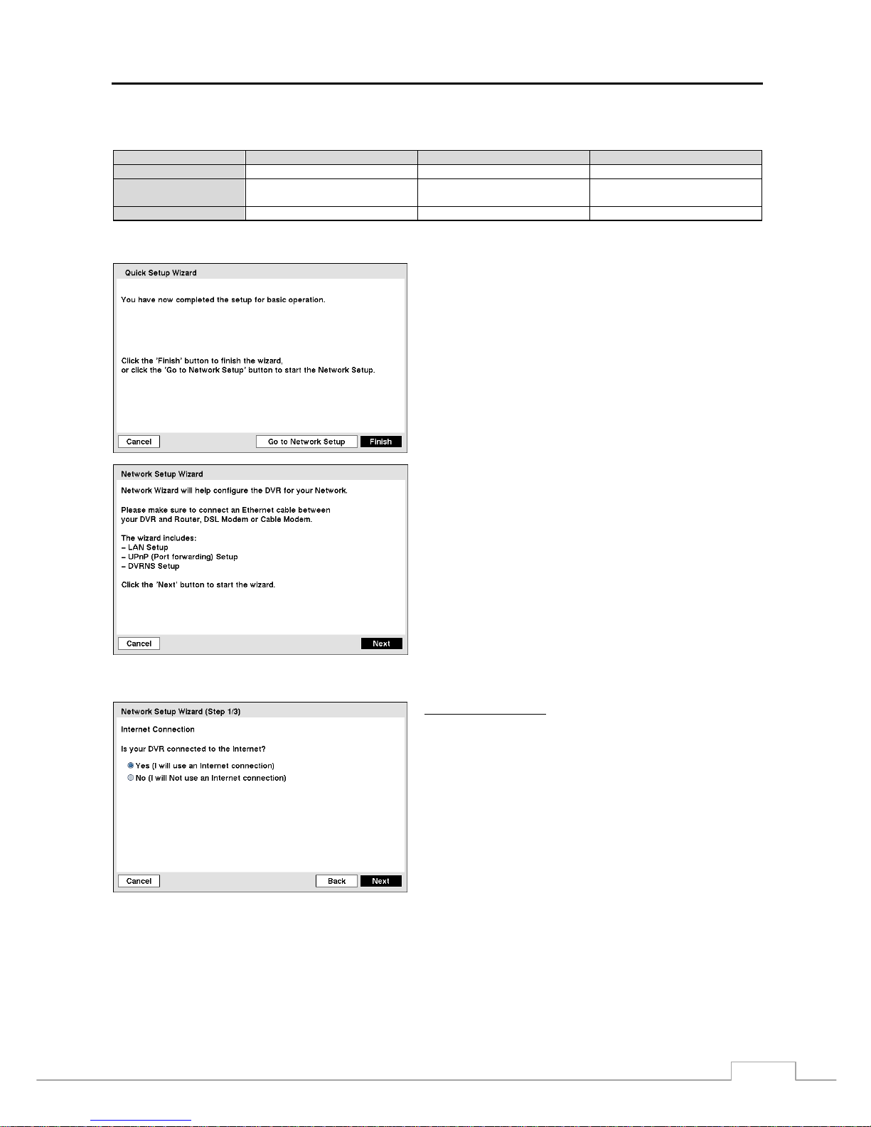
NOTE: The recording quality and recording speed of each camera channel will be set as show below according
to the Record Method and Record Video Quality you set.
HVQPP* SRP* LRTPP*
Motion Event Record Very High / 30 ips High / 5 ips Standard / 3 ips
Continuous &
Motion Event Record
Very High / 30 ips (Time)
Very High / 30 ips (Event)
High / 5 ips (Time)
Very High / 30 ips (Event)
Standard / 3 ips (Time)
High / 5 ips (Event)
Continuous Record Very High / 30 ips High / 5 ips Standard / 3 ips
* Record Video Quality: HVQPP (High Video Quality Priority Profile) , SRP (Standard Recording Profile), LRTPP (Longer Reco rding Time
Priority Profile)
Select the Finish button to finish the Quick Setup Wizard and
select the Go to Network Setup button to start the Network
Setup.
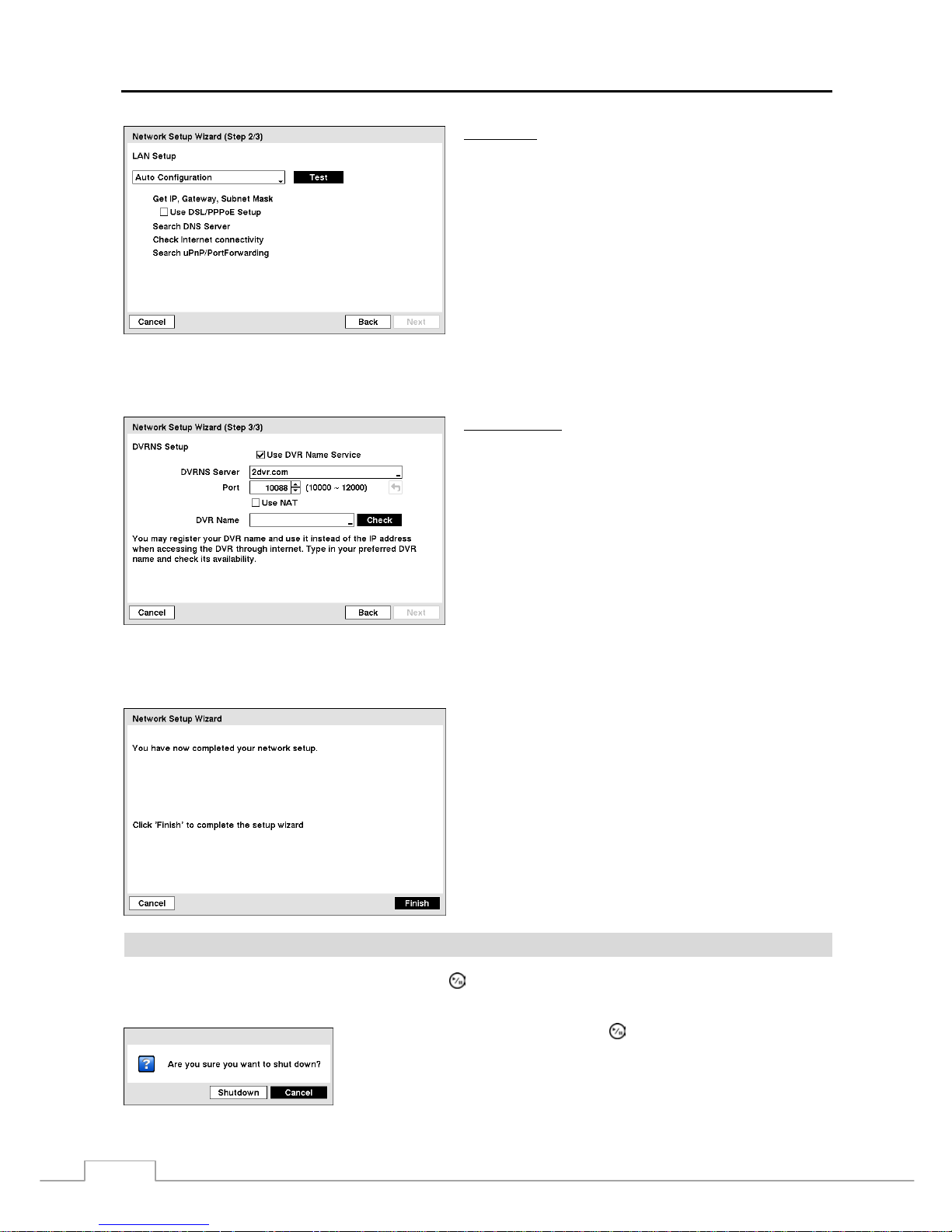
Figure 18 — Network Setup wizard screen.
If you selected the Go to Network Setup, select the Next
button to start the Network Setup Wizard.
Internet Connection
Select whether or not your DVR is connected to the Internet.
Page 28
User’s Manual
20
LAN Setup
Select between Auto Configuration and Manual Configuration
for network configuration, and then select the Test button to
test the network configuration you selected.
NOTE: Selecting Auto Configuration allows the DVR to
automatically obtain LAN parameters (IP address,
Gateway, Subnet Mask and DNS Server address).
Selecting Manual Configuration allows you to set
up LAN parameters manually.
NOTE: The network configuration you set should be tested
by selecting Test, otherwise the Next button will
cannot be selected, and you cannot move to the
next step.
Use DSL/PPPoE Setup: Selecting the box allows you to set up the DSL network. Entering the ID and password
for DSL connection is required.
DVRNS Setup
Use DVR Name Service: Select the box to use the DVR
Name Service.
DVRNS Server: Enter the IP ad dress or domain name of
the DVRNS server.
Port: Set the port number of the DVRNS server.
Use NAT: Select the box to use the NAT (Network Address
Translation) device.
DVR Name: Enter the DVR name to be registered on the
DVRNS server.
Check: Select the box to check whether or not the name
you entered can be used.
NOTE: The DVR name you entered should be checked by selecting Check, otherwise the DVRNS changes will
not be saved.
When entering no name or a name already registered on the DVRNS server, an error message displays.
Select the Finish button to finish the Setup Wizard.
Shutdown
Highlight Shutdown in the System menu and press the
button. The Shutdown screen displays asking you to confirm
whether or not you want to shut the system down.
After selecting Shutdown and pressing the
button, a screen will appear telling
you when it is safe to disconnect power.
Figure 19 — Shutdown screen.
Page 29
Digital Video Recorder
21
Network Setup
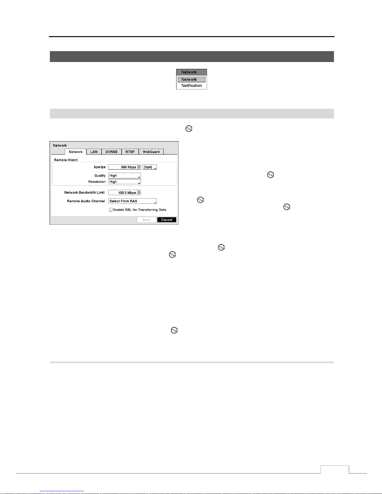
Figure 20 — Network menu.
Network
Highlight Network in the Network menu and press the
button.
Highlight the first box beside Remote Watch – bps/ips.
You can select the Transfer Speed from 50Kbps to 100Mbps.
Highlight the second box beside Remote Watch – bps/ips.
You can select the unit of measure for the transfer speed
between: bps and ips. Press the button to set the transfer
speed.
Highlight the box beside Remote Watch – Quality and press
the
button. You can select the Quality from: Very High,
High, Standard and Basic. Press the
button to set the
Quality.
Figure 21 — Network setup screen.
Highlight the box beside Remote Watch – Resolution and press the button. You can select the Resolution from:
High (Half D1) and Standard (CIF). Press the
button to set the Resolution.
NOTE: The higher Quality and Resolution settings require higher Transfer Speed settings. The transfer speed
you set is the maximum speed. Depend ing on the net work environment, this speed may not be achiev ed.
You can limit the network bandwidth settings so that system does not consume too much network bandwidth. Highlight
the box beside Network Bandwidth Limit and press the Up and Down arrow buttons to set the desired maximum
bandwidth from 50Kbps to 100Mbps.
NOTE: When limiting the network bandwidth, the remote watch image on the PC running RAS or WebGuard
might not be displayed properly.
The DVR supports two-way audio communication between a local system and a PC running RAS. Highlighting the box
beside Remote Audio Channel and pressing the
button allows you to select the audio channel that sends audio to
the remote site. Selecting Select From RAS will send audio of the channel selected from RAS.
NOTE: Depending on network conditions, audio might be interrupted or out of synchronization during
transmission.
Highlight the LAN tab, and the LAN screen displays.
Page 30
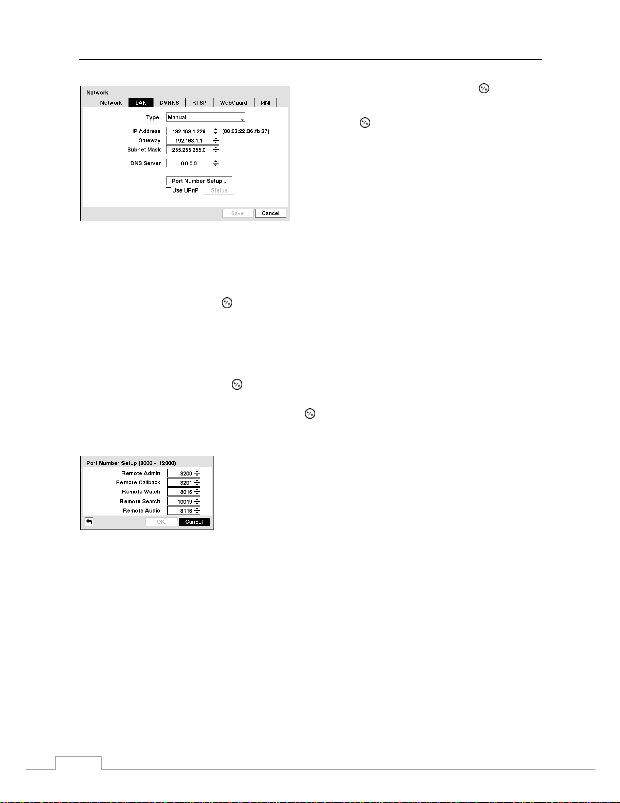
User’s Manual
22
Figure 22 — LAN (Manual) setup screen.
Highlight the box beside Type and press the button. You
can select the type of network configuration from: Manual,
DHCP and ADSL (with PPPoE). Select the desired type
and press the
button.
Selecting Manual from the Type allows you to set up LAN
parameters manually.
Change the numbers by highlighting them and using the Up
and Down arrow buttons to increase or decrease the number.
The factory default LAN settings are:
IP Address: 192.168.1.229
Gateway: 192.168.1.1
Subnet Mask: 255.255.255.0
NOTE: You will need to get the appropriate IP Address, Gateway and Subnet Mask from your network
administrator.
Highlight the box beside DNS Server. Press the Up and Down arrow buttons to set the IP address of the DNS server.
Highlight Use UPnP and press the button to toggle between On and Off. When it is On, port forwarding from the
NAT (Network Address Translation) device to the DVR will b e enabled automat ically via UPnP ( Universal Plug and
Play) service. This function will be especially useful when accessing a port on a private IP address.
NOTE: For the UPnP service to work, the NAT device should support the UPnP Port Forwarding function and
the function should be set to enabled.
You cannot change the port settings when Use UPnP is On.
Highlight the Status box and press the button to display the port numbers forwarded from the NAT device via UPnP
service.
Highlight the Port Number Setup… box and press the button. The Port Number Setup screen appears.
NOTE: You will need to get the appropriate Port Numbers for each RAS and WebGuard related program (Admin,
Callback, Watch, Search and Audio) from your network administrator.
Change the numbers by highlighting them and using the Up and Down arrow
buttons to increase or decrease the number. The factory default Port settings are:
Remote Admin: 8200
Remote Callback: 8201
Remote Watch: 8016
Remote Search: 10019
Remote Audio: 8116
NOTE: The system restarts automatically after changing the port settings.
Do NOT use the same port number for two different programs, otherwise, the DVR cann ot be connec ted
with the PC running RAS or WebGuard.
CAUTION: When changing the port settings, you must change the port settings on the PC running
RAS as well. Refer to the RAS manual for details.
Page 31
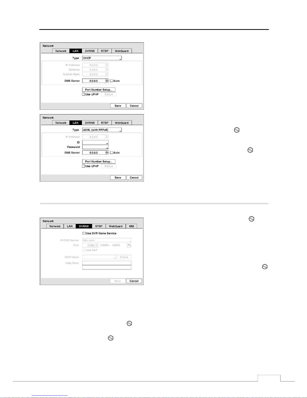
Digital Video Recorder
23
Selecting DHCP from the Type and highlighting Save button
reads the current IP address of the DVR configured by DHCP
(Dynamic Host Configuration Protocol) network.
Selecting ADSL (w ith PPPoE) allows you to set up the ADSL
network.
Highlight the box beside ID and press the button. A
virtual keyboard appears allowing you to enter the ID for
ADSL connection.
Highlight the box beside Password and press the button.
A virtual keyboard appears allowing you to enter the password
for ADSL connection.
NOTE: Entering the ID and Password and highlighting
OK reads the current IP address of the DVR
configured by the ADSL network.
NOTE: A If the DVR is configured for DHCP or an ADSL
network, the IP address of the DVR might change
whenever the unit is turned on.
Highlight the DVRNS tab, and the DVRNS screen displays.
Highlight Use DVR Name Service and press the
button
to toggle between On and Off.
NOTE: The DVRNS (DVR Name Service) allo ws the DVR to
use Dynamic IP addresses for remote connect ion.
When this feature is On, you can a ccess your DVR
remotely using the DVR name instead of its IP
address. For the DVRNS feature, the DVR should
be registered on the DVRNS server.
Highlight the box beside DVRNS Server and press the
button. A virtual keyboard appears allowing you to enter the
IP address or domain name of the DVRNS server.
Figure 23 — DVRNS setup screen.
NOTE: You will need to get the IP Address or domain name of the DVRNS Server from your network administrator.
You can use the domain name instead of IP address if you already set up the DNS Server when setting
up the LAN.
Highlight the box beside Port and press the button. Set the port number of the DVRNS server using the Up and
Down arrow buttons to increase or decrease the numbers.
Highlight Use NAT and press the button to toggle between On and Off.
NOTE: When using the NAT (Network Address T ranslation ) device, ref er to the NA T manufacture r’s instru ctions
for the proper network settings.
Page 32
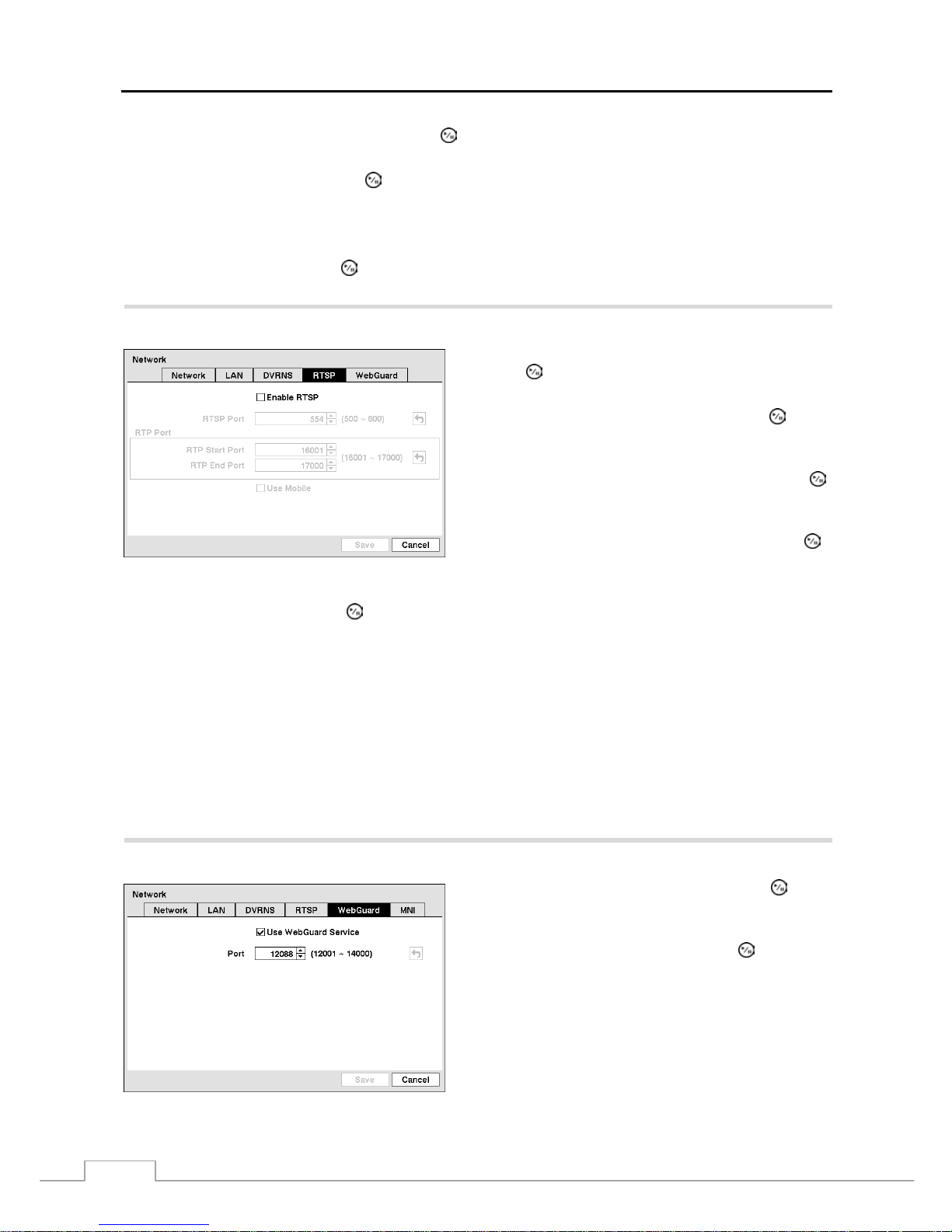
User’s Manual
24
Highlight the box beside DVR Name and press the
button. A virtual keyboard appears allowing you to enter the
DVR name to be registered on the DVRNS server.
Highlight the Check box and press the button to check whether or not the name you entered can be used.
NOTE: The DVR name you entered should be checked by selecting Check, otherwise the DVRNS changes will
not be saved.
When entering no name or a name already registered on the DVRNS server, an error message displays.
Highlighting Save and pressing the button registers the DVR on the DVRNS server. Proper DVRNS settings will
display the help desk information of the DVRNS server in the box beside Help Desk.
Highlight the RTSP tab, and the RTSP setup screen displays.
Figure 24 — RTSP setup screen.
Highlight Enable RTSP (Real-Time Streaming Protocol) and
press the
button to toggle between O n a n d Of f . Yo u w i ll
be able to change the settings if Enable RTSP is enabled.
Highlight the box beside RTSP Port and press the button.
Set the port number of the RTSP server obtained from your
system administrator.
Highlight the box beside RTP Start Port and press the
button. Set the start port number of the RTP server obtained
from your system administrator.
Highlight the box beside RTP End Port and press the
button. Set the end port number of the RTP server obtained
from your system administrator.
Highlight Use Mobile and press the
button to toggle between On and Off. When s et to o n, you can access a remote
DVR using a Blackberry or other mobile devices.
NOTE: Selecting Use Mobile sets the WebGuard service to be enabled automatically regardless of your WebGuard
settings.
When using NAT (Network Address Translation) or firewall services, opening all UDP ports allows you
to access a DVR using Blackberry and Android devices.
You can access a remote DVR and monitor live video images using media players, such as VLC Player,
supporting RTSP service. Start the media player on your local PC and enter “rtsp://ID:Password@IP
address:RTSP port number/track ID=‘channel number’”, or start Internet Explorer on your Blackberry
or other mobile devices and enter “http://IP address:Webguard port number/”.
Some media players might play video properly depending on network conditions.
RTSP service might not be supported, depending on the type of media player.
Highlight the WebGuard tab, and the WebGuard screen displays.
Highlight Use WebGuard Service and press the
button
to toggle between On and Off. See Appendix – WebGuard
for detailed descriptions of the WebGuard service.
Highlight the box beside Port and press the button. Set
the port number used when accessing WebGuard by using
the Up and Down arrow buttons to increase or decrease the
numbers.
Figure 25 — WebGuard setup screen.
Page 33
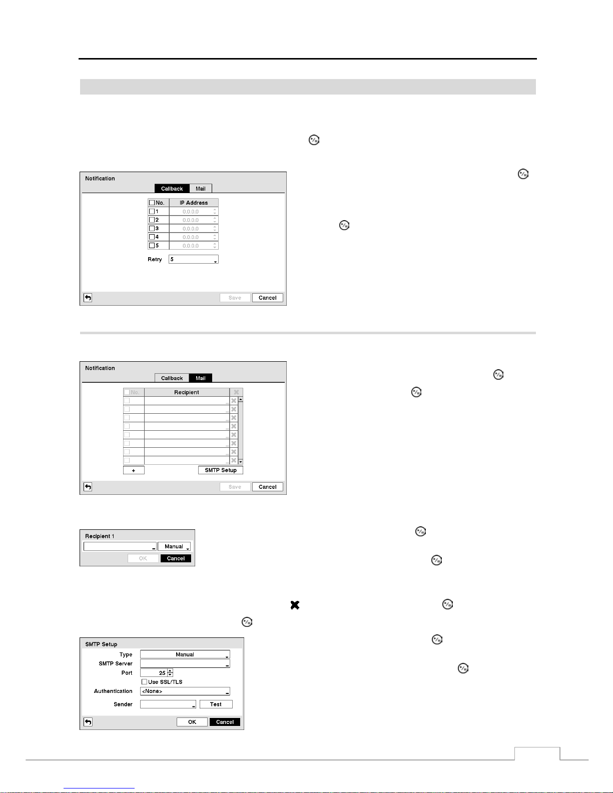
Digital Video Recorder
25
Notification
The DVR can be set up to contact a computer running RAS (Remote Administration System) or to send an email when
an event occurs.
Highlight Notification in the Network menu and press the
button. The Notification screen displays. You will be
able to change the Callback and Mail settings.
Figure 26 — Notification Callback setup screen.
Highlight the box under the No. heading and press the
button to toggle between On and Off. When LAN is turned
On you can change the IP addresses.
Highlight the IP Address box that you want to change and
press the
button. Use the arrow buttons to enter the IP
address of the computer you want contacted during an event.
You can enter up to five IP addresses.
Highlight the box beside Retry and enter the number of times
you would like the DVR to try contacting the computer. You
can select from 1 to 10 retries.
Highlight the Mail tab, and the Mail screen displays.
Figure 27 — Notification Mail setup screen.
The Mail account can be turned On or Off by highlighting
the boxes under the No. heading and pressing the
button.
Highlight the + and press the button to add a mail recipient.
Highlight the first box under Recipient and press the button. A virtual keyboard
appears that you can use to enter the recipient’s e-mail address.
Highlight the second box under Recipient and press the button. You can select
between Manual and listed SMTP mail server providers.
NOTE: The e-mail address must include the “@” character to be a valid address.
The Mail accounts can be deleted by highlighting the beside the account and pressing the button.
Highlight SMTP Setup… and press the
button. The SMTP Setup screen appears.
Highlight the box beside Type and press the button. You can select
between Manual and listed SMTP mail server providers.
Highlight the box beside SMTP Server and press the button. A virtual
keyboard appears that you can use to enter the IP address or domain name
of the SMTP server.
NOTE: You will need to get the IP Address or domain name of the
SMTP Server from your network administrator.
Page 34
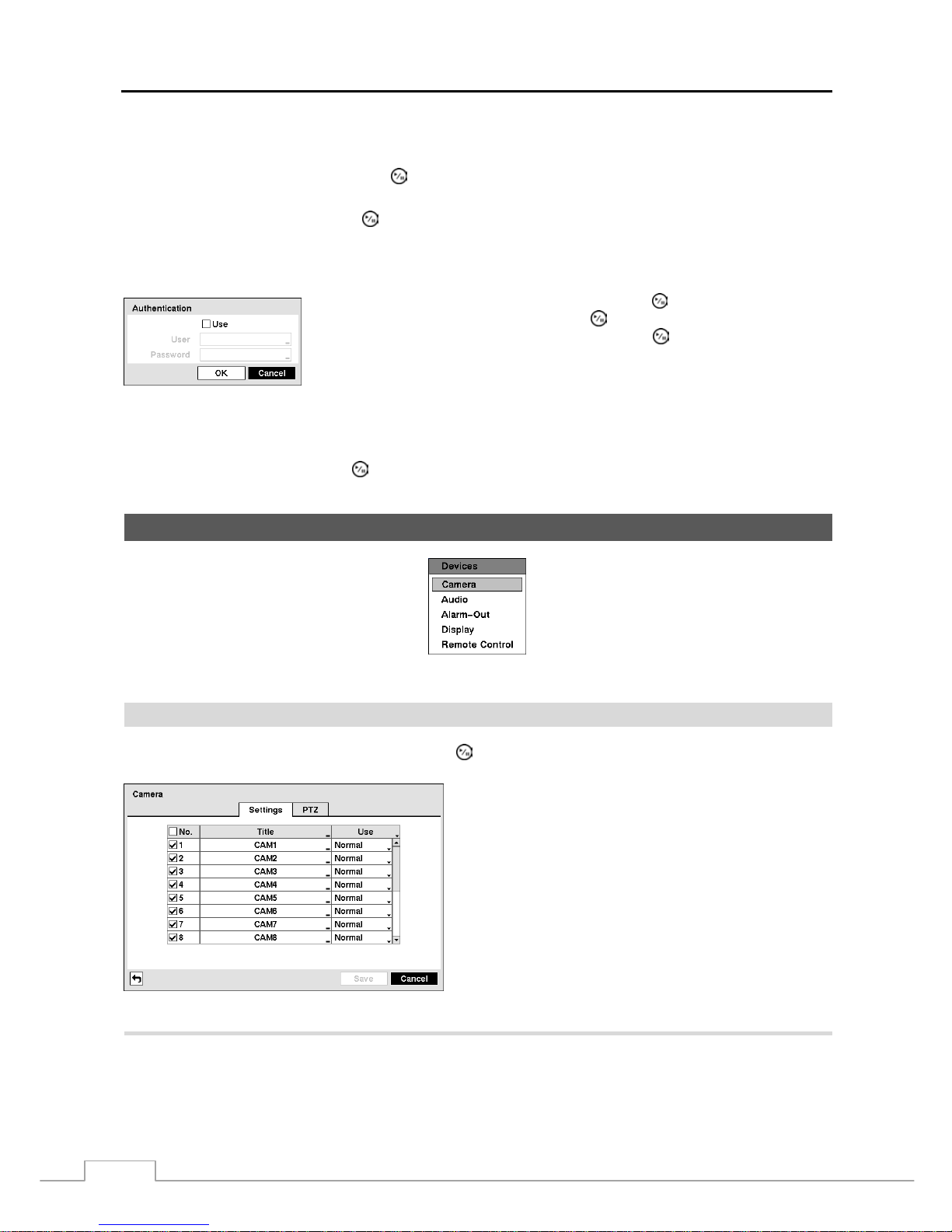
User’s Manual
26
NOTE: You can use the domain name instead of IP address if you already set up the DNS Server when setting
up the LAN.
Highlight the box beside Port and press the button. Use the arrow buttons to enter the SMTP Server port number
obtained from your system administrator. The default port number is 25.
Highlight Use SSL/TLS and press the button to toggle between On and Off. When it is On, the DVR can send an
email via an SMTP server requiring SSL (Secure Sockets Layer) authentication.
NOTE: This product includes softw are developed by the OpenSSL Project for use in the OpenSSL T oolki t
(http://www.openssl.org/).
Highlight the box beside Authentication and press the button. An Authentication
screen appears. Highlight Use and press the
button to toggle between On and Off.
Highlight the box beside User/Password and press the
button. A virtual keyboard
appears allowing you to enter the user ID and password.
Highlight the box beside Sender and enter the sender’s e-mail address. Use th e virtual keyboard to enter the e-mail
address.
NOTE: The e-mail address must include the “@” character to be a valid address.
Highlight the Test box and press the button to test emailing with the current settings you made.
Devices Setup
Figure 28 — Devices menu.
Camera
Highlight Camera in the Devices menu and press the
button. The Camera setup screen appears.
Figure 29 — Camera setup screen.
You can turn the camera number On or Off, and you can
change the Title of each camera us ing the vir tual k e yboard.
You can also determine which cameras will display on the
monitors by selecting Normal, Covert 1 or Covert 2 from
a drop-down list in the Use column.
NOTE: When selecting the Covert 1, the DVR displays
the camera title and status icons on the co vert
video. When selecting the Covert 2, the DVR
displays only camera title on the covert video.
NOTE: A user who does not have Covert Camera View
authority cannot view video from cameras set to
Covert 1 or Covert 2 in both the live monitoring
and playback modes.
Highlight the PTZ tab, and the PTZ setup screen displays.
Page 35
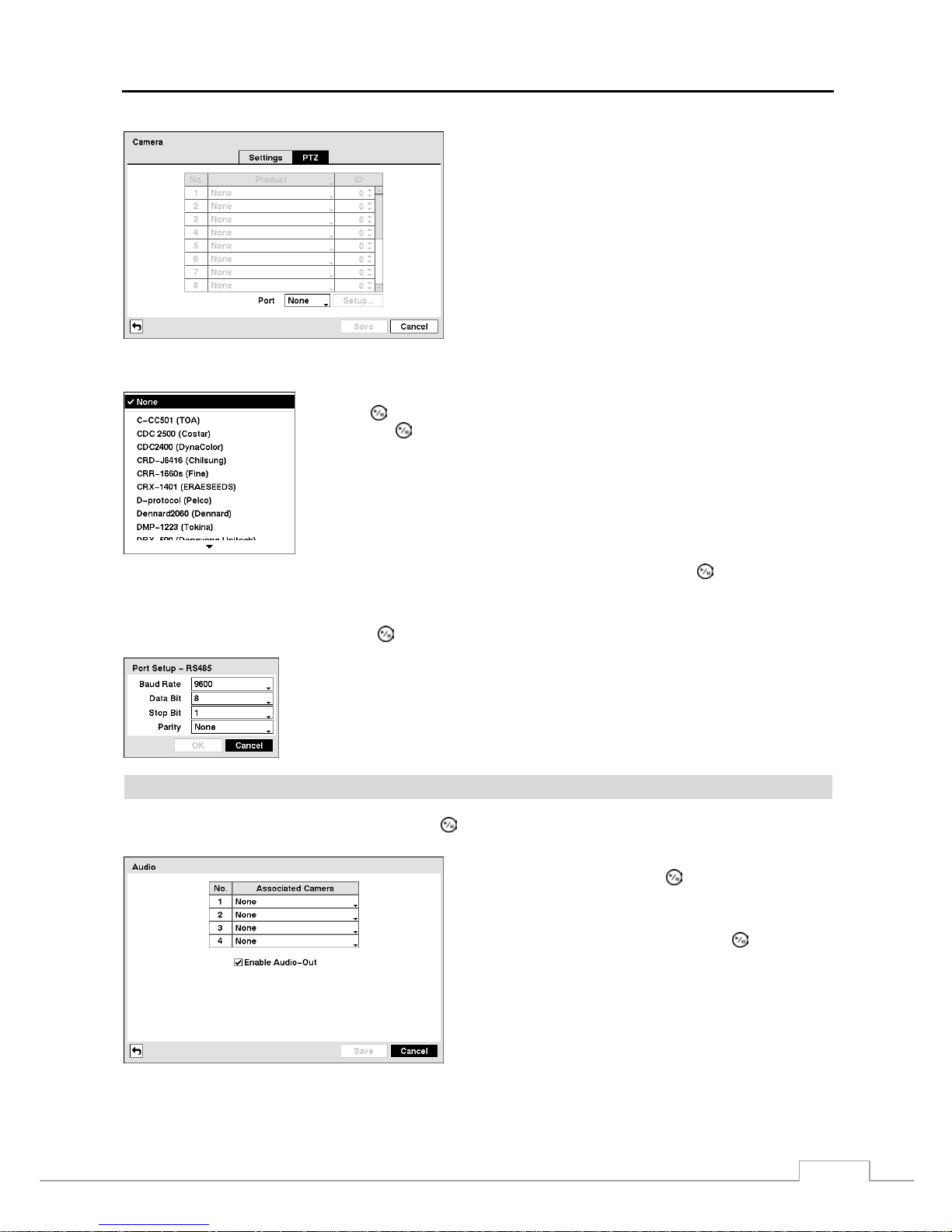
Digital Video Recorder
27
NOTE: You will only be able to set up PTZ devices if the
PTZ port is set to RS232 or RS485.
Figure 30 — Camera PTZ setup screen.
Highlight the box in the Product column for the PTZ camera you wish to configure and
press the
button. A list of PTZ devices appears. Select your camera from the list
and press the
button. You will need to connect the camera to the RS232 or RS485
connector on the back of the DVR following the camera manufacturer’s instructions.
You can assign IDs to each camera by highlighting the box under the ID heading and pressing the button. Change the
number by highlighting it and using the Up and Down arrow buttons to increase and decrease the number. The PTZ
ID number can be set from 0 to 256.
Highlight the Setup… box and press the button. The Port Setup window appears.
Configure the port’s setting based on the PTZ camera manufacturer’s instructions.
Audio
Highlight Audio in the Devices menu and press the
button. The Audio setup screen appears.
The DVR can record up to four audio inputs. Highlight the
box beside the input and press the
button. A list of cameras
appears, and you can sel ect which cam era you want asso ciated
with that audio input.
Highlight Enable Audio-Out and press the button. This
toggles between enabling and disabling audio out.
Figure 31 — Audio setup screen.
Page 36
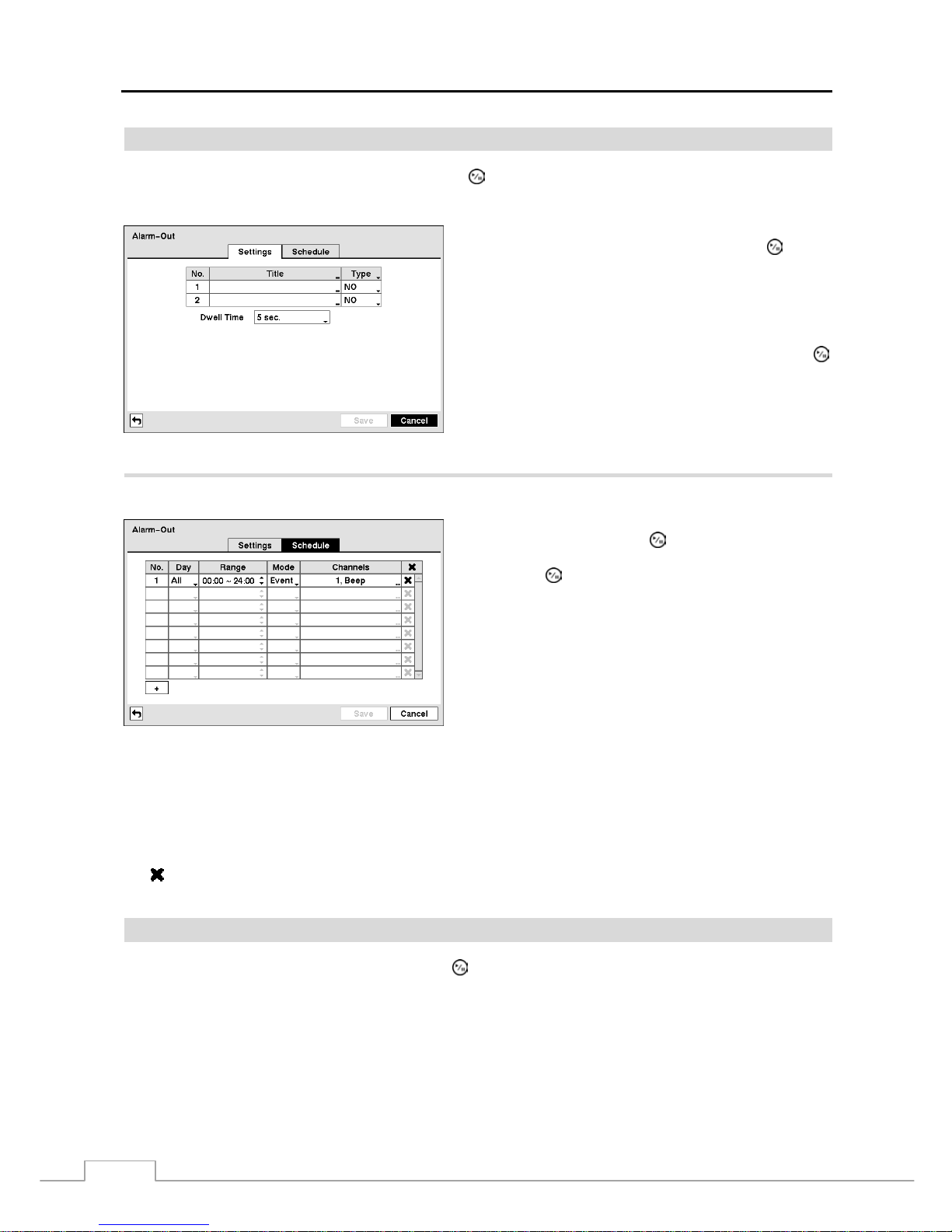
User’s Manual
28
Alarm-Out Screen
Highlight Alarm-Out in the Devices menu and press the
button. The Alarm-Out screen allows you to change the
settings and establish a schedule for each alarm output from the DVR.
Each alarm output can be given its own title by highlighting
the box under the Title heading and pressing the
button.
A virtual keyboard appears allowing you to enter the title.
Highlighting the box under the Type heading allows to set
the alarm output for NO or NC (normally open or normally
closed).
Highlighting the box beside Dwell Time and pressing the
button allows you to set the dwell time of the alarm output.
Dwell times range from 5 seconds to 30 minutes.
Figure 32 — Alarm-Out Settings screen.
Highlighting the Schedule tab causes the Schedule screen to display.
You can add and edit alarm output schedules on this screen.
Highlight the + and press the button to add a schedule.
Highlighting the boxes under the Column heading and
pressing the button allows you to edit the information in
those boxes.
The Day box allows you to select the days that the alarm
schedule will be active. The choices are: Sun, Mon, Tue,
Wed, Thu, Fri, Sat, M~F, Hol and All.
The Range box allows you to set the time that the alarm
schedule will be active in 15-minute increments from 00:00
to 24:00.
Figure 33 — Alarm-Out Schedule screen.
The Mode box allows you to set how the alarm reacts during the scheduled time. When set to On, the Alarm-Out is
active during the scheduled time. When set to Event, the Alarm -Out is only activ e when ther e is a n Event during the
scheduled time.
The Channels box allows you to set which alarm outputs will be active. You can also select the DVR’s internal buzzer.
The box allows you to delete an alarm output schedule. You will be asked to confirm whether or not you really wish
to delete the schedule.
Display
Highlight Display in the Devices menu and press the
button. The Display screen allows you to select what
information will be displayed on the monitor.
Page 37
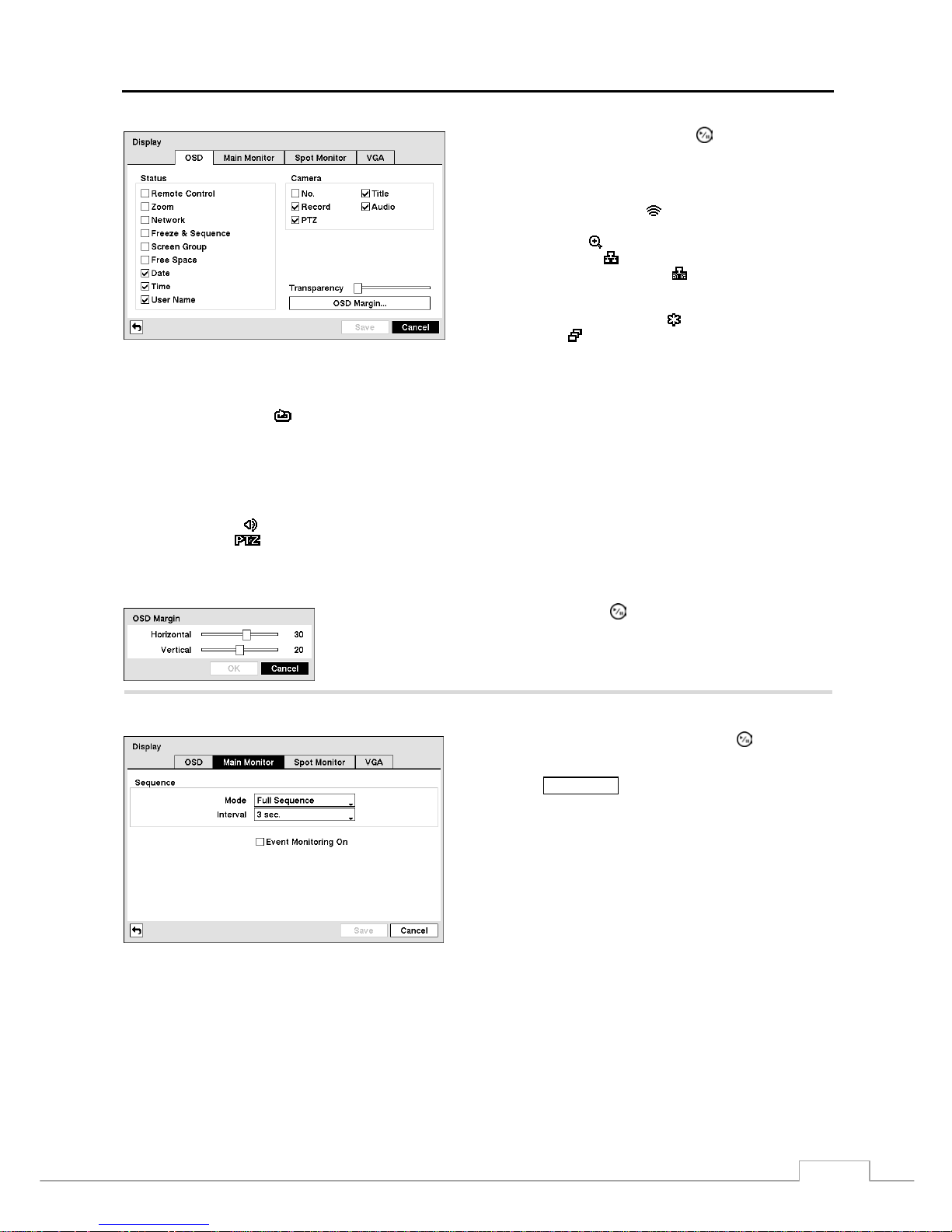
Digital Video Recorder
29
Figure 34 — Display OSD screen.
Highlighting an item and pressing the button toggles that
item On and Off. When an item is On, there is a checkmark
in the box beside it. The following items can be turned On
or Off:
Remote Control – The icon
displays when the DVR can be
controlled by the infrared remote control.
Zoom – The icon
displays on the enlarged video.
Network – The icon
displays when the unit is connected to
a network via Ethernet. The icon
displays on each camera
when audio communication is available between the DVR and
a PC running RAS via Ethernet.
Freeze & Sequence – The icon
displays while in the Freeze
mode, and the
displays while in the Sequence mode.
Screen Group – The number of screen group displays when
the DVR is not in the 4x4 display mode of the 16-channel DVR,
and 3x3 mode of the 8-channel DVR.
Free Space – The icon
displays when the DVR is in the Recycle mode, a nd the pe rcenta ge of available stora ge space dis plays
when the DVR is not in the Recycle mode.
Date/Time – The current date and time information displays.
User Name – The name of the current user logged in displays.
Camera No. – The camera number displays at the top-left corner of each camera screen.
Camera Title – The camera title displays at the top-left corner of each camera screen.
Record – The record related icons display on each camera screen.
Audio – The icon
displays on each camera screen for which the DVR can play live audio.
PTZ – The icon
displays on each PTZ camera screen.
You can adjust the transparency of the setup screens by highlighting Transparency and using the Left and Right arrow
buttons.
Highlighting OSD Margin… and pressing the button displays how OSD text will
be displayed on the monitor. You can adjust the horizontal and vertical margins
so that text and icons will not be hidden beyond the edges of the monitor.
Highlight the Main Monitor tab to switch to the Sequence screen.
Figure 35 — Main Monitor screen.
Highlight the box beside Mode and press the button. You
can select between Full Sequence and Cameo Sequence.
Pressing th e SEQUENCE button causes the DVR to sequence
cameras, and the DVR can sequence cameras in two modes:
“Full” and “Cameo”. In the Full mode, the DVR sequences
through the cameras and displays them full screen. In the
Cameo mode, the bottom right window in a multi-screen
format sequences through the cameras.
NOTE: Any cameras that are Off, have lost video or are set
to Covert (unless the user has authority to view
covert cameras) will be excluded from the Cameo
sequence.
You can define the screen layout in a variety of formats and set the DVR to sequence through the different screen layouts
(pages) so that all the cameras will be displayed. You can also set up the DVR to display one camera or a group of
cameras all the time while cycling through the remaining cameras in a “cameo” window. This can be done with one
camera displayed full screen while displaying the cameo window as a PIP (picture in picture), or displaying the cameras
in a grid pattern with the bottom right window as the cameo.
NOTE: Sequence cannot be used in the 4x4 display mode of the 16-channel, and 3x3 mode of the 8-channel DVR.
Page 38
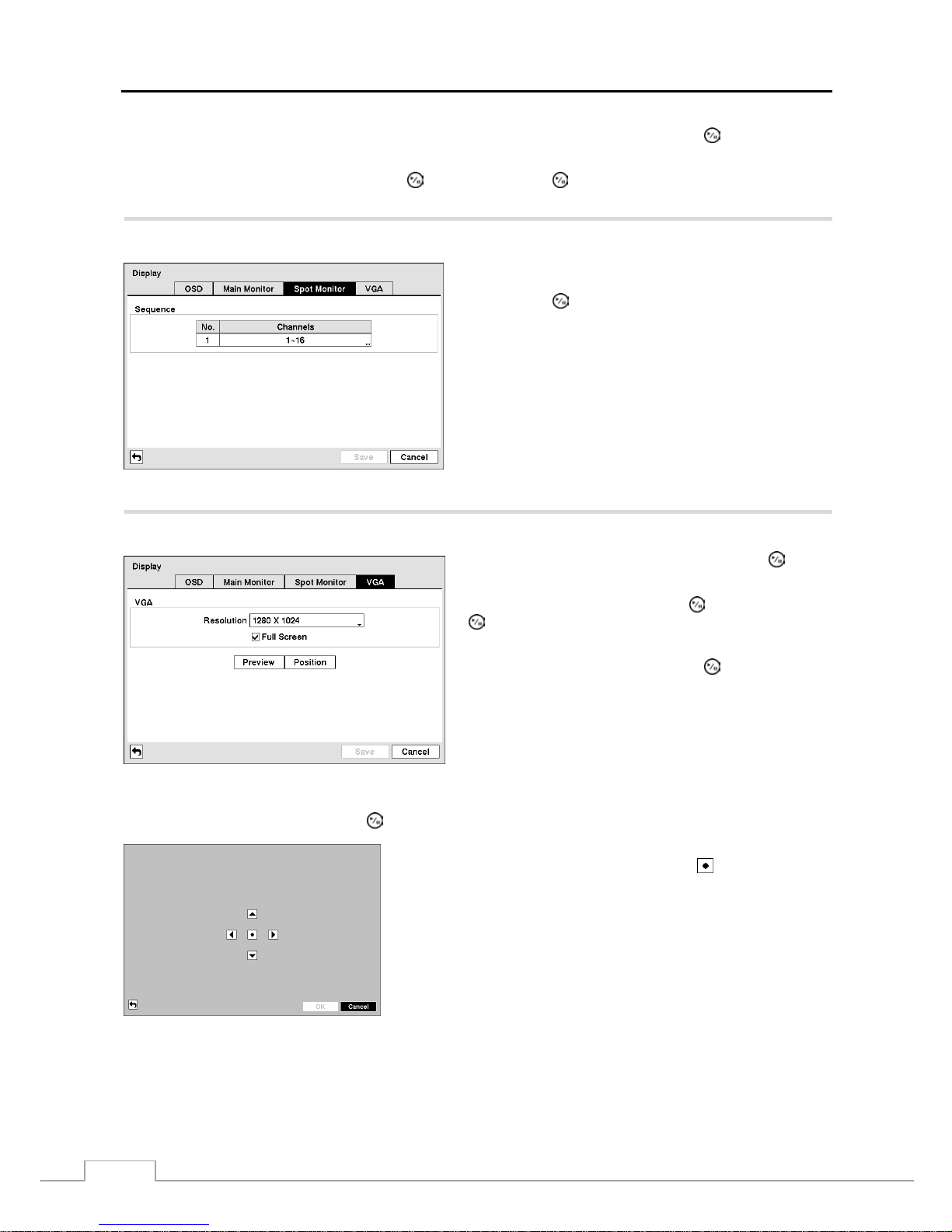
User’s Manual
30
You can adjust the display dwell time by highlighting the box beside Interval and pressing the
button. You can
select dwell intervals ranging from 1 second to 1 minute.
Highlight Event Monitoring On and press the button. Pressing the button toggles between On and Off. When
it is On, the DVR will display the camera associated with the event when an event occurs.
Highlight the Spot Monitor tab to switch to the Spot Monitor screen.
You can define which cameras display sequentially on the
Spot Monitor. Highlight the box in the Channels column
and press the
button.
Figure 36 — Spot Monitor screen.
Highlight the VGA tab to switch to the VGA screen.
Highlight the box beside Resolution and pr ess the
button.
You can select from 800x600, 1024x768 and 1280x1024.
Highlight Full Screen and press the button. Pressing the
button toggles between On and Off. When it is On, the
screen on the VGA monitor displays in full screen mode.
Highlighting Preview and pressing the button allows you
to preview how the screen will be displayed on the VGA
monitor.
Figure 37 — VGA screen.
Highlighting Position and pressing the button allows you to adjust the screen position on the VGA monitor.
Use the arrow buttons on the setup screen to move the VGA screen
position in the direction you want. Selecting the
button at the center
returns to the previous position.
Page 39
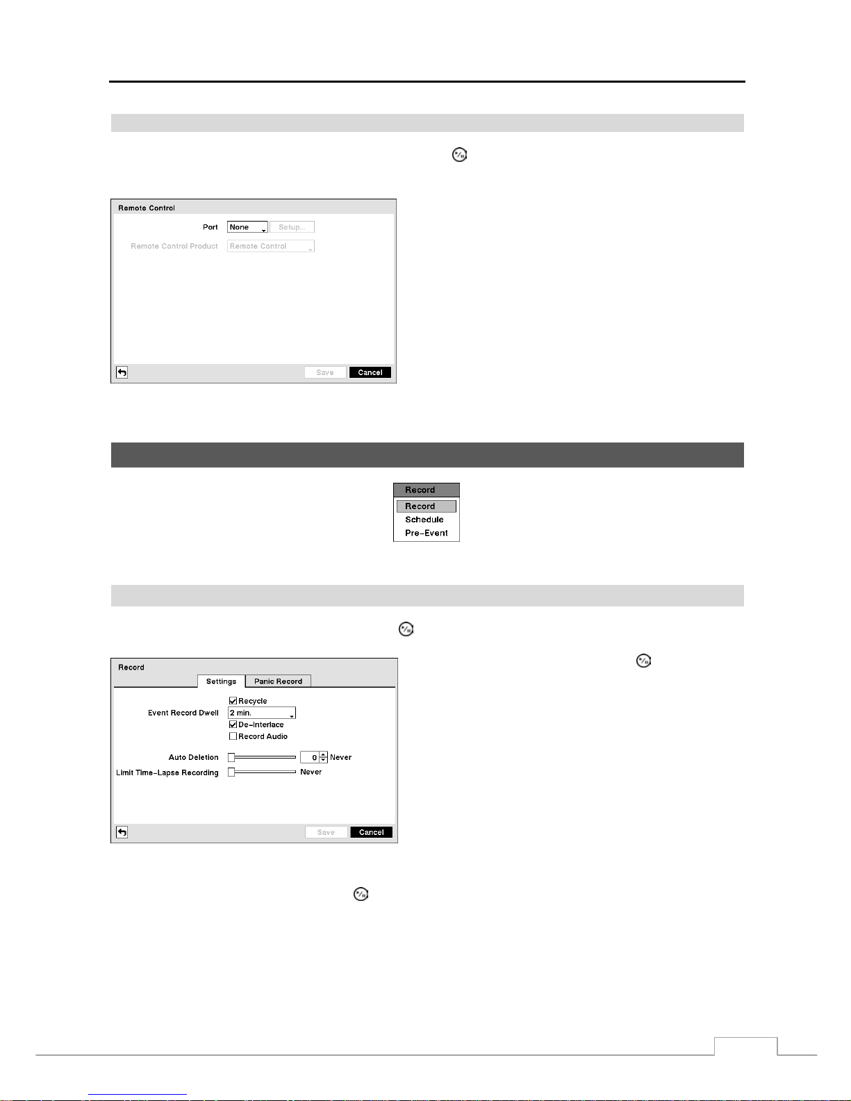
Digital Video Recorder
31
Remote Control
Highlight Remote Control in the Devices menu and press the
button. The Remote Control setup screen allows
you to select a port and make correct settings for a remote keyboard.
Highlight the box beside Port and select from None, RS232
and RS485. If the RS232 port and RS485 port are in use for
PTZ control, networking or text input, the remote keyboard
cannot be configured.
Highlight Setup… and select the correct Baud Rate, Parity,
Data Bits and Stop Bits for the device you are con necting to
the DVR.
Highlight the box beside Remote Control Product and
select the device from the list.
Figure 38 — Remote Control setup screen.
Recording Setup
Figure 39 — Record menu.
Record
Highlight Record in the Record menu and press the
button. The Record setup screen appears.
Highlighting Recycle and pressing the
button toggles
between On and Off. In the Recycle mode, the DVR records
over the oldest video data once all available storage space
has been used. When Recycle is turned off, the DVR stops
recording once all available storage space has been used.
Highlight the Event Record Dwell box and set the length of
time you would like to record for the associated event. You
can set the dwell from 5 seconds to 30 minutes. Refer to Event
Actions screen in this chapter for information regarding event
recording.
Figure 40 — Record Settings screen.
Highlighting De-Interlace and pressing the
button toggles between On and Off. When set to On, the DVR will
turn the de-interlace filter on while recording video with Very High (D1) resolution.
NOTE: The video signal has a time difference of 1/60 second (1/50 second for PAL) between odd and even fields
because it is composed of 60 inte rlaced f ield s per s econd (50 f ields fo r PAL). When reco rding v ideo with
Very High (D1) resolution, video is mad e up of fram e unit s combini ng t wo fields – one odd field and one
even field. This can cause horizontal scan lines or flas hes in areas with motion because of the time
difference between the two fields. Turning on the de-interlace filter provides clearer video by eliminating
these horizontal scan lines and flashes.
Page 40
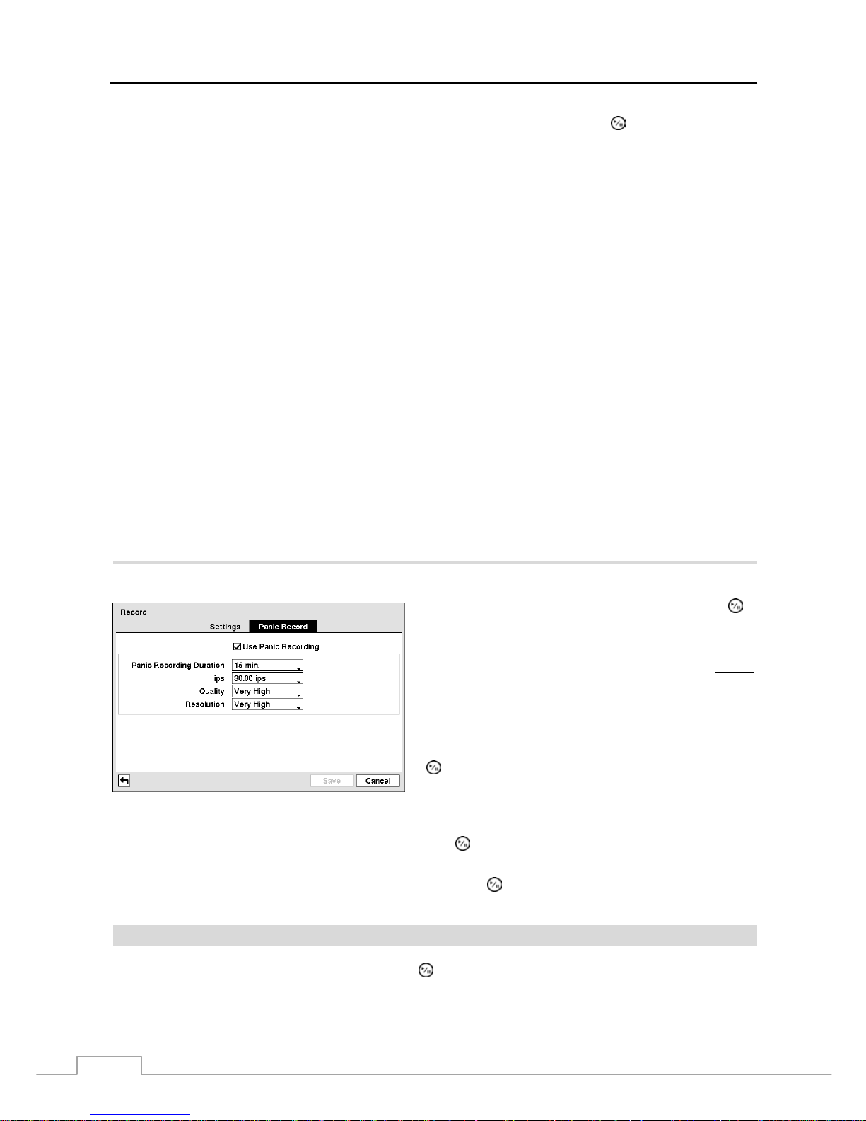
User’s Manual
32
The DVR can record up to four audio inputs. Highlighting Record Audio and pressing the
button toggles between
On and Off.
Highlight the slide bar beside Auto Deletion, and use the Left and Right arrow buttons or Up and Down arrow buttons
to adjust the length of time recorded data will be kept from 1 to 999 days. The DVR automatically deletes vi deo
recorded earlier than the user-defined period under three conditions: at midnight, whenever the system reboots or
whenever the user changes the Auto Deletion settings. Selecting Never will disable the Auto Deletion function.
Highlight the slide bar beside Limit Time-Lapse Recording, and use the Left and Right arrow bu ttons to adjust the
length of the maximum storage time for time-lapse recording from 1 to 99 days. The Limit Time-Lapse Recording
feature will function when the storage device has enough space to record video data longer than the preset period.
When this feature is On, the DVR records over the oldest “time-lap se” video once all av ailable stor age has be en used
in the Recycle mode, so more event video can be saved. Selecting Never will disable the Limit Time-Lapse Recording
function.
NOTE: When the storage dev ice do es not have enough space to record video data longer than the preset Lim it
Time-Lapse Recording period, the DVR records over the oldest video data (time-lapse or event video)
as it would in the Recycle mode even if this feature is turned On.
The maximum storage time is only an estimate because the amount of space required to store video
varies depending on many factors such as motion and image complexity.
CAUTION: When more than one disk is installed in the u n it, the DVR records video on the disks
sequentially based on time. And these sequentially recorded videos have the advantage
that you can search recorded video easily even though a disk is removed from the unit.
However, video recorded in the same time range might be saved on different d i sks by
channel and by the type of recording mode. Once the Limit Time-Lapse Reco rding is
set to On, the DVR will maintain this recording limitation even after disabling the function.
If you want the DVR to record video on the disks sequentially based on time again, you
must format all disks that are currently used for recording.
Highlight the Panic Record tab, and the Panic Record setup screen appears.
Figure 41 — Panic Record screen.
Highlighting Use Panic Recording and pressing the
button toggles between On and Off.
Highlight the Panic Recording – Duration box and set
the duration of panic recording. Panic recording will stop
automatically after the preset duration as long as the
PANIC
button is not pressed to stop the panic recording. You can
set the dwell from 5 minutes to 1 hour. Select No Limit if
you want to stop panic recording manually.
Highlighting the Panic Recording – ips and pressing the
button allows you to set the images per second for Panic
recording. You can select from 1.00 to 30.00 ips (25.00 ips
PAL).
Highlighting the Panic Recording – Quality and pressing the
button allows you to set the recorded image quality
for Panic recording. You can select from: Very High, High, Standard and Basic.
Highlighting the Panic Recording – Resolution and pressing the button allows you to set the recorded image
resolution for Panic recording. You can select from: Very High (D1), High (Half D1) and Standard (CIF).
Schedule
Highlight Schedule in the Record menu and press the
button, and the Schedule setup screen appears.
Page 41
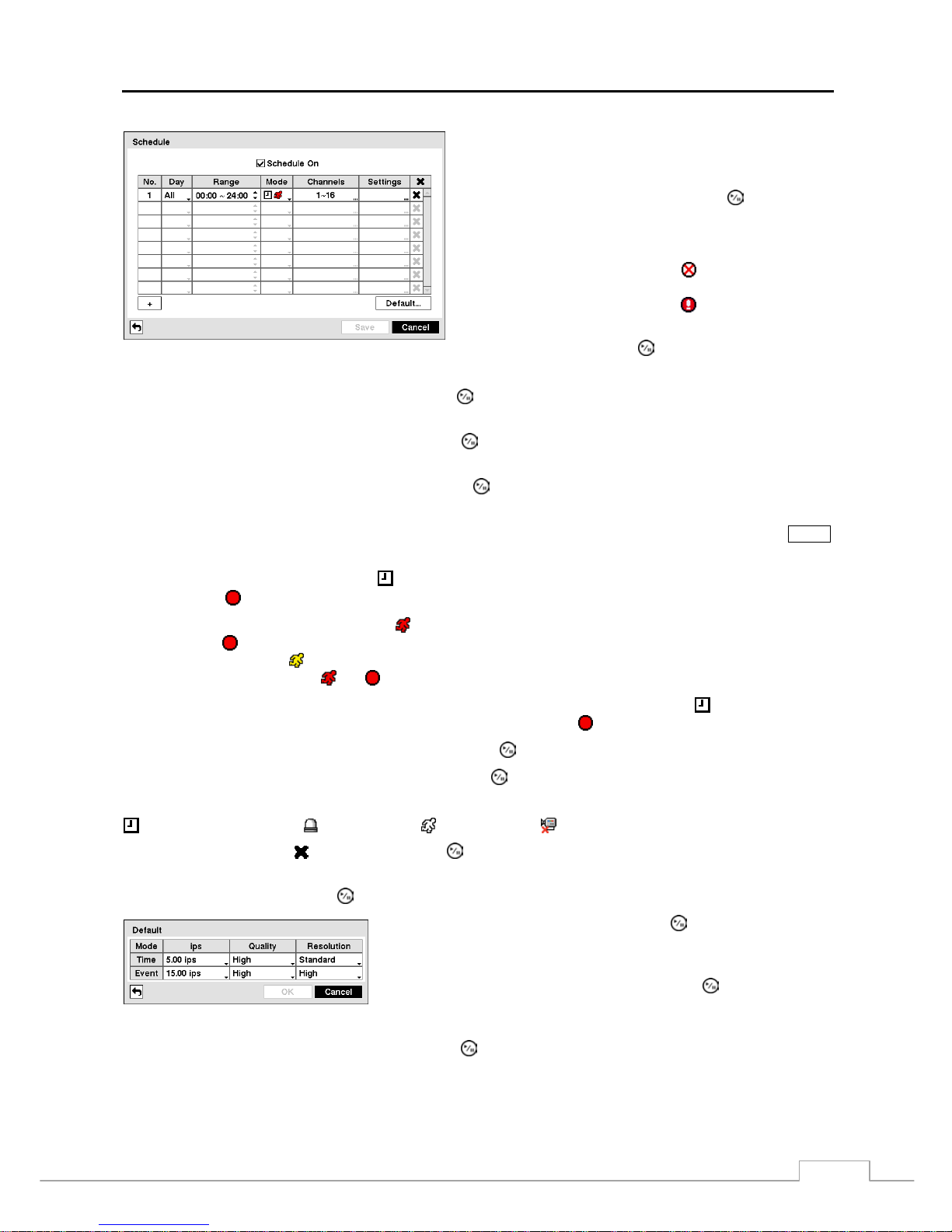
Digital Video Recorder
33
Figure 42 — Schedule setup screen.
You can program the DVR to record only during certain times
based on time, day of the week, and holidays. The smallest
time segment you can use is 15 minutes.
Highlighting Schedule On and pressing the button toggles
between On and Off. In the Schedule On mode, the DVR
records video based on the schedule established in the Schedule
screen. When turning Schedule recording Off, you will be
asked to confirm your decision, and displays at the top-left
corner of each camera screen. Panic recording will function
even when Schedule is turned off.
displays during panic
recording.
Highlight the + and press the
button to add a schedule item.
Highlight the box under the Day heading and press the
button to change the days that the scheduled recording will
take place. Choose from: Sun, Mon, Tue, Wed, Thu, Fri , Sat, M~F, Hol and All.
Highlight the box under the Range heading and press the
button to change the time range that the scheduled recording
will take place. The smallest time segment you can use is 15 minutes.
Highlight the box under the Mode heading and press the
button to change the recording mode that will be used.
Choose from: No Record, Time, Event and Time & Event.
When the DVR is in the No Record mode, it will not record during the preset day and time range as long as the
PANIC
button is not pressed. Use the No Record mode when you do NOT want the DVR to record during certain times.
When the DVR is in the Time
mode
, the icon displays at the top-left corner of the screen. The DVR will record
and displays the
icon at the top-left corner of the screen during the scheduled times.
When the DVR is in the Event mode, the red icon displays at the top-left corner of the screen. The DVR will record
and displays the
icon at the top-left corner of the screen when any event occurs. When the DVR is in the Pre-Event
recoding mode, the yellow
icon displays when there is no event, a nd the DVR is not r ecording. When the DVR is
in the Pre-Event mode, the red
and display when any event occurs and the DVR starts recoding.
When the DVR is in the Time & Event mode, the DVR will follow the Time settings and the icon displays at the
top-left corner of the screen. The DVR follows the Event settings and the
icon displays.
Highlight the box under the Channels heading and press the
button to select which cameras will be recorded.
Highlight the box under the Settings heading and press the
button to define the recording settings.
NOTE: Descriptions of the Record icons in the Type column are as follows:
Time-lapse (Time) Alarm-In Motion Video Loss
Highlight the box under the heading and press the
button to delete the recording settings. You will be asked to
confirm that you want to delete the settings.
Highlight Default… and press the
button. The Default screen appears.
Highlighting boxes under ips and pressing the
button allows you to set
the images per second for Time and Event recording. You can select from
1.00 to 30.00 ips (25.00 ips PAL).
Highlighting boxes under Quality and pressing the button allows you
to set the recorded image quality for Time and Event recording. You can
select from: Very High, High, Standard and Basic.
Highlighting boxes under Resolution and pressing the button allows you to set the recorded imag e r esolution for
Time and Event recording. You can select from: Very High (D1), High (Half D1) and Standard (CIF).
Page 42
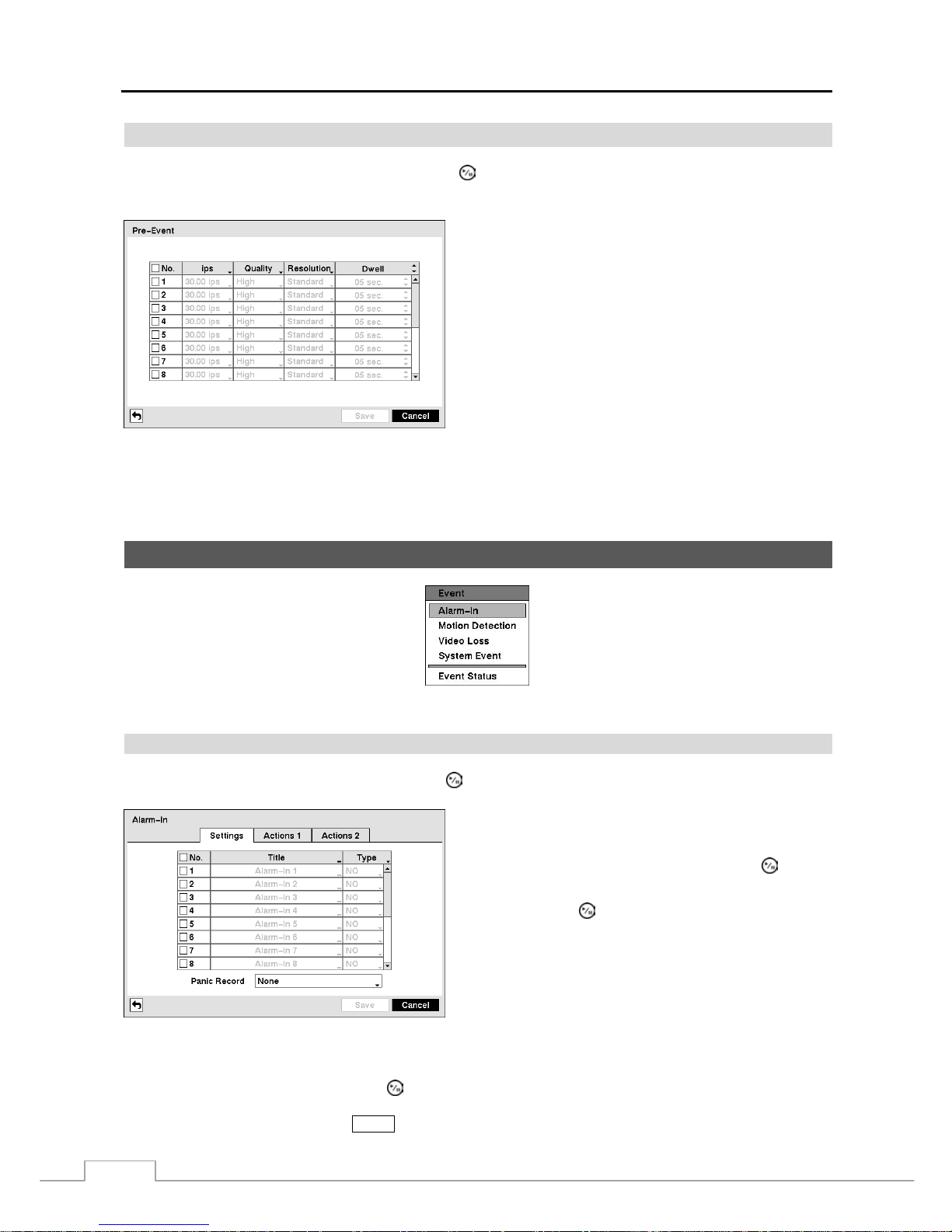
User’s Manual
34
Pre-Event
Highlight Pre-Event in the Record menu and press the
button, and the Pre-Event setup screen appears. If you do
not have Event set up in the Record Schedule, a message will display alerting you to this fact.
Figure 43 — Pre-Event setup screen.
When the DVR is in the Event Record mode it is possible to
have it record images before the event occurs. The Pre-Event
screen allows you to define how to handle pre-event recording.
You can turn individual cameras On or Off for pre-event
recording. The image speed can be set from 1.00 to 30.00 ips
(25.00 ips PAL), image quality can be selectable from Very
High, High, Standard and Basic, and image resolution can
be selectable from Very High (D1), High (Half D1) and
Standard (CIF).
You can set the amount of time to record prior to the event
by adjusting the Dwell. You can set the Dw el l from 5 s econds
to 30 seconds. The longer the dwell set, the fewer maximum
ips can be set.
NOTE: When the DVR is in t he Time or Time & Event mode, it ignores the pre-event settings and follows the
time settings.
Event Setup
Figure 44 — Event menu.
Alarm-In
Highlight Alarm-In in the Event menu and press the
button. The Alarm-In setup screen appears.
The alarm terminal strip on the back of the DVR has inputs
associated with each alarm. You can set up each input on the
Alarm-In screen. You can turn each input On or Off by
highlighting the alarm number and pressing the
button.
Each input can be given a title. Highlight the desired Title
box and press the
button. A virtual keyboard appears
allowing you to enter a title name.
Each input can be set as NO (normally open) or NC (norm ally
closed).
Figure 45 — Alarm-In Settings screen.
You can set up the DVR to start panic recording whenever it senses an input on one of its alarm input connectors. Highlight
the box beside Panic Record and press the
button. A list of Alarm Inputs appears, and you can select which alarm
input you want associated with panic recording. The DVR will continue panic recording until an input on the selected
alarm input is released as long as the
PANIC button is not pressed to stop the panic recording.
Page 43
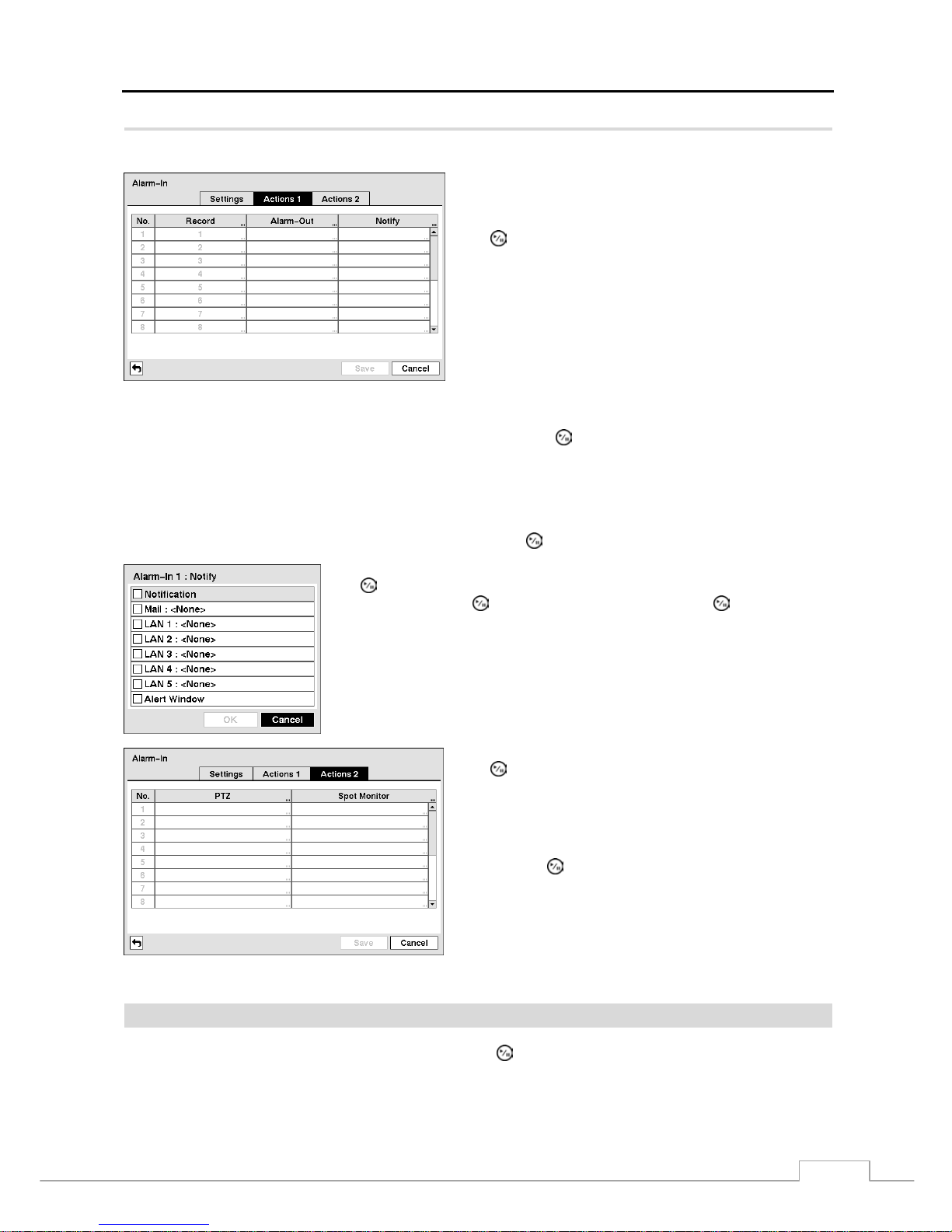
Digital Video Recorder
35
Highlight the Actions 1 and Actions 2 tabs, and the Actions 1 and Actions 2 setup screens appear.
You can set the actions the DVR will take whenever it senses
an input on one of its alarm input connectors.
Highlight the desired box under the Record heading, and press
the
button. A list of cameras appears. Select the cameras
that you want the DVR to record whenever it detects an input
on the associated alarm input.
NOTE: For the Record action, the camera you select
should be set to the Event or Time & Event
recording mode in the Record Schedule setup
screen.
Figure 46 — Alarm-In Actions 1 screen.
Highlight the desired box under the Alarm-Out heading, and press the
button. A list of Alarm Outputs and Beep
appear. Select the Alarm Output connectors that you would like to activate whenever the DVR detects an input on the
associated alarm input. You can also set the DVR’s internal buzzer to sound.
NOTE: For the Alarm-Out action, the alarm output and beep you select should be set to the Event mode in the
Alarm-Out setup screen (Schedule tab).
Highlight the desired box under the Notify heading, and press the
button. The Alarm-In Notify menu appears.
You can toggle the entire list On and Off by highlighting Notification and pressing
the button. You can toggle the individual items On and Off by highlighting that
item and pressing the button. Highlight OK and press the
button to accept
your changes.
NOTE: For the Notify action, the notify item you select should be enabled in
the Notification setup sc r ee n and th e DVR should be registered in th e
RAS (Remote Administration System).
Highlight the desired box under the PTZ heading, and press
the
button. A list of PTZ presets appear. Select the preset
position for each PTZ camera, where you want PTZ cameras
to move to whenever the DVR detects an input on the
associated alarm input.
Highlight the desired box under the Spot Monitor heading,
and press the button. A list of SP OT moni tors and cameras
appears. Each SPOT mo nitor can be associated w ith a camera.
The DVR will display the associated camera on the SPOT
monitor whenever it detects an input on the associated alarm
input.
Figure 47 — Alarm-In Actions 2 screen.
Motion Detection
Highlight Motion Detection in the Event menu and press the
button. The Motion Detection setup screen appears.
Page 44
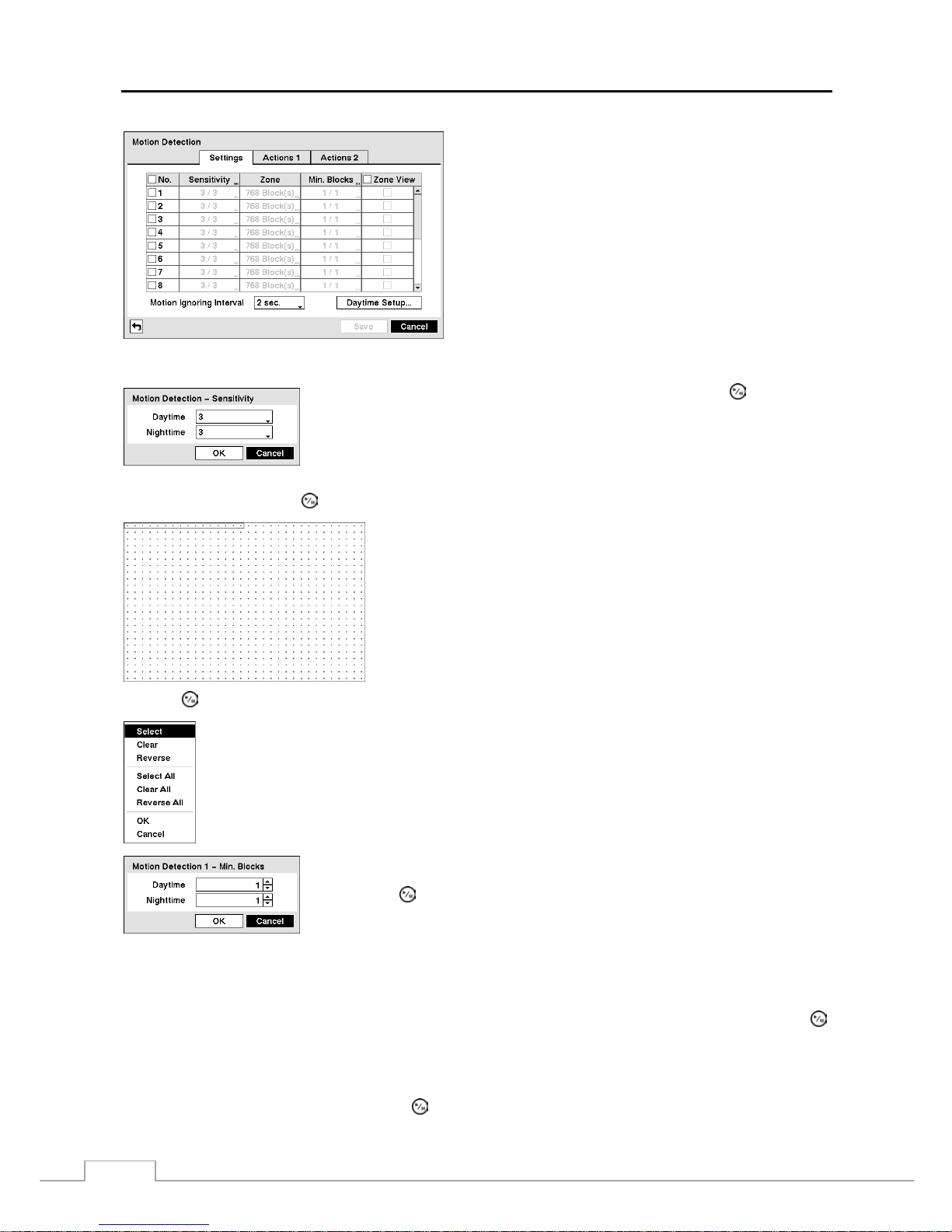
User’s Manual
36
Your DVR has built-in video motion detection. Video motion
detection can be turned On or Off for each camera.
Figure 48 — Motion Detection Settings screen.
Highlighting the box under the Sensitivity heading and pressing the
button allows
you to adjust the DVR’s sensitivity to motion for Daytime and Nighttime independently.
There are five settings with 1 being the least sensitive and 5 being the most sensitive.
You can define the area of the image where you want to detect motion; e.g., a doorway. Highlight the box under the
Zone heading, and press the
button. The Motion Detection Zone screen displays.
The Motion Detection Zone screen is laid over the video for the s elected
camera. You can set up motion detection zones by selecting or clearing
blocks.
NOTE: You can set up motion zones one block at a time in groups of
8 or 16 individual block groups (8- and 16-channel DVR
respectively). A block group is pos itioned within th e image area
using the Up and Down arrow buttons, and individual blocks
within the block groups are selected or cleared using the camera
buttons.
Press the button to display the menu screen. The menu on the setup screen has the following functions:
Select — Activates highlighted blocks to detect motion.
Clear — Deactivates highlighted blocks so that they will not detect motion.
Reverse — Activates inactive highlighted blocks and deactivates active highlighted blocks.
Select All — Activates all blocks to detect motion.
Clear All — Deactivates all blocks so that they will not detect motion.
Reverse All — Activates inactive blocks and deactivates active blocks.
OK — Accepts changes and closes Zone setup.
Cancel — Exits Zone setup without saving changes.
You can adjust the minimum number of detection blocks that must be activated to
trigger a motion alarm. Highlighting the box under the Min. Blocks heading and
pressing the
button allows you to adjust the minimum number of detection blocks
for Daytime and Night time indep endently. Sm aller numbers provide greater sensitivity
because fewer detection blocks must be activated.
Turning Zone View On will allow you to observe how the DVR is reacting to motion. When in the m otion viewin g
mode, the detection zone of video will be displayed. Any detected motion within the zone will be displayed in red.
You can control excessive event logging and remote notification of motions detected after the motion dwell time by
adjusting the motion ignoring dwell intervals. Highlight the box beside Motion Ignoring Interval and press the
button. A list of intervals ranging from 1 to 10 seconds or Never appears. The DVR will not log and notify motion
events occurred during the preset interval range.
NOTE: The record action for moti on events will not be affected by the Motion Ignoring function.
Highlighting Daytime Setup and pressing the button allows you to set up the Daytime range.
Page 45
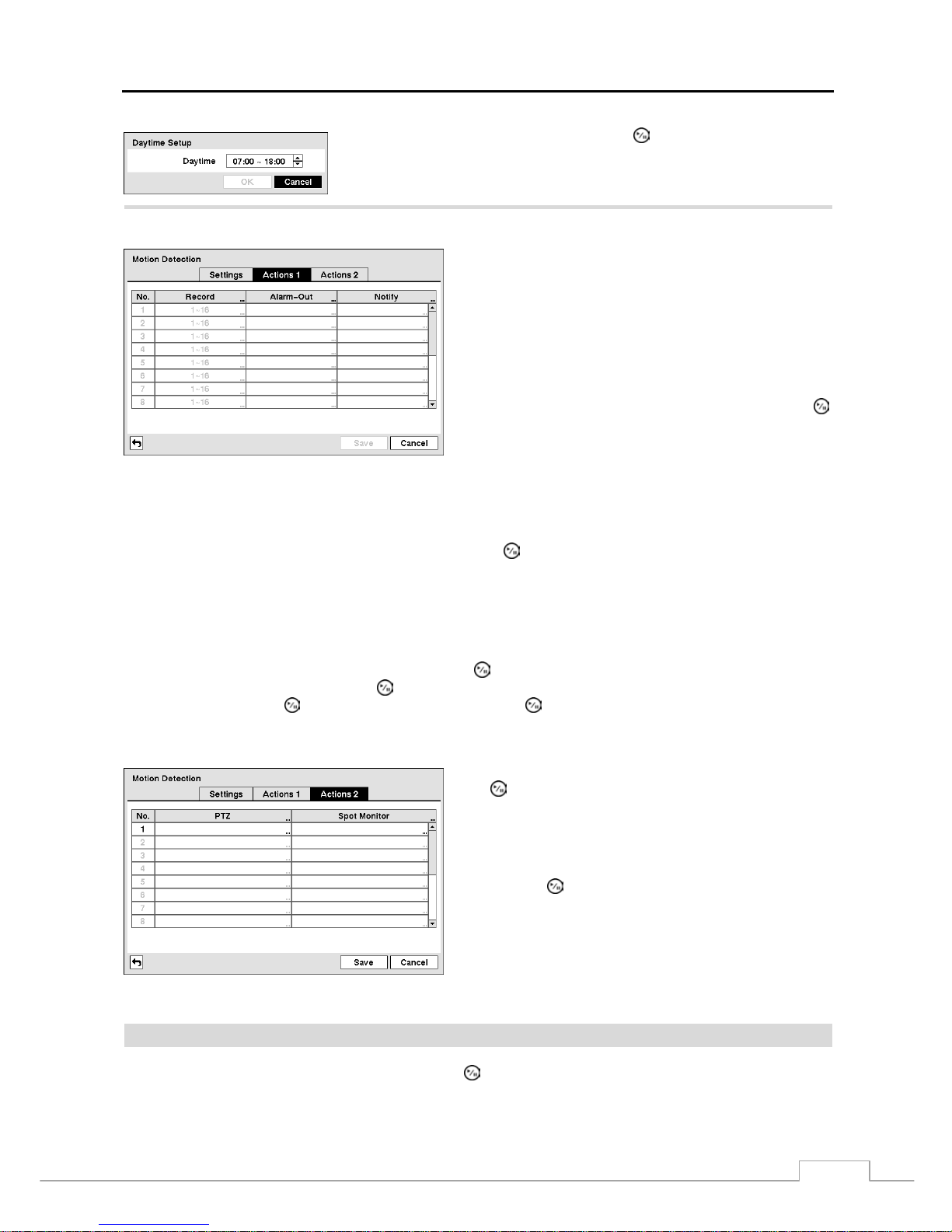
Digital Video Recorder
37
Highlight the box beside Daytime and press the button. Use the Up and Down
arrow buttons to set the Daytime range. The DVR will consider the remaining
time range as the Nighttime.
Highlight the Actions 1 and Actions 2 tabs and the Motion Detection Actions 1 and Actions 2 screens display.
Figure 49 — Motion Detection Actions 1 screen.
The DVR can be set to react to motion detection differently
for each camera. Each camera can be associated with another
camera, trigger an Alarm-Out connector, sound the DVR’s
internal buzzer, notify a number of different devices, move
PTZ cameras to preset positions, and/or display a camera on
a SPOT monitor.
NOTE: You can associate multiple cameras with a camera
that detects motion.
Highlight the box under the Record heading and press the
button. A list of cameras appears. You can associate as many
cameras with that camera as you wish. If the DVR detects
motion on the selected camera, it starts recording video from
all the associated cameras.
NOTE: For the Record action, the camera you s elect should b e set to the Event or Time & Event recording mo de
in the Record Schedule setup screen.
Highlight the box under the Alarm-Out heading and press the button. A list of Alarm Outputs appears. You can
associate as many Alarm-Outs with that camera as you wish. When the DVR d etects motion on the se lected camera’s
input, it triggers output signals on all the associated Alarm-Out connectors. You can also have the DVR’s internal
buzzer sound if motion is detected on the selected camera.
NOTE: For the Alarm-Out action, the alarm output and beep you select should be set to the Event mode in the
Alarm-Out setup screen (Schedule tab).
Highlight the box under the Notify heading and press the button. You can toggle the entire list On and Off by
highlighting Notification and pressing the
button. You can toggle the individual items On and Off by highlighting
that item and pressing the
button. Highlight OK and press the button to accept your changes.
NOTE: For the Notify action, the notify item you select should be enabled in the Notification setup screen and
the DVR should be registered in the RAS (Remote Administration System).
Highlight the desired box under the PTZ heading, and press
the
button. A list of PTZ presets appear. Select the preset
position for each PTZ camera, where you want PTZ cameras
to move to whenever the DVR detects motion on the selected
camera’s input.
Highlight the desired box under the Spot Monitor heading,
and press the
button. A list of SP OT moni tors and cameras
appears. Each SPOT mo nitor can be associated w ith a camera.
The DVR will display the associated camera on the SPOT
monitor whenever it detects motions on the selected camera.
Figure 50 — Motion Detection Actions 2 screen.
Video Loss
Highlight Video Loss in the Event menu and press the
button. The Video Loss setup screen appears.
Page 46
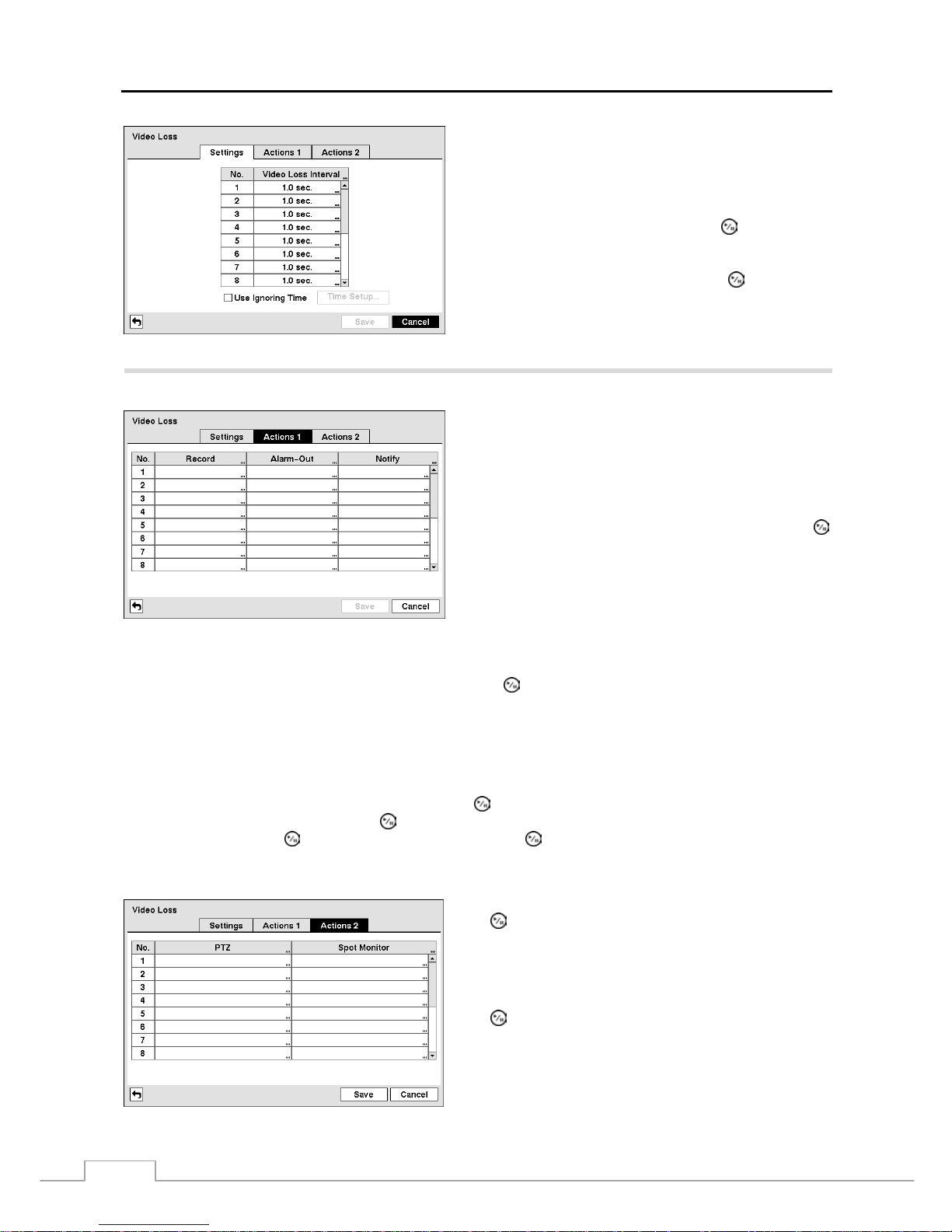
User’s Manual
38
Figure 51 — Video Loss Settings screen.
Highlighting the box under the Video Loss Interval heading
allows you to set the duration of a signal loss before the DVR
will report a Video Loss. The DVR will not consider an y signal
loss from a camera to be a Video Loss if the detect ed signal
loss is shorter than the interval set on this screen.
Highlight Use Ignoring Time and press the button to toggle
between On and Off. When set to On, the DVR will ignore
video loss events occurring during the preset period.
Highlighting Time Setup and pressing the
button allows
you to set up event ignoring time.
Highlight the Actions 1 and Actions 2 tabs and the Video Loss Actions 1 and Actions 2 screens display.
Figure 52 — Video Loss Actions 1 screen.
The DVR can be set to react to video loss differently for each
camera. Each camera can be associated with another camera,
trigger an Alarm-Out connector, sound the DVR’s internal
buzzer, notify a number of different devices, move PTZ
cameras to preset positions, and/or display a camera on a
SPOT monitor.
Highlight the box under the Record heading and press the
button. A list of cameras appears. You can associate as many
cameras with that camera as you wish. If the DVR detects
video loss on the selected camera, it starts recording video
from all the associated cameras.
NOTE: For the Record action, the camera you select should
be set to the Event or Time & Event recording mode
in the Record Schedule setup screen.
Highlight the box under the Alarm-Out heading and press the button. A list of Alarm Outputs appears. You can
associate as many Alarm-Outs with that camera as you wish. When the DVR detects video loss on the selected camera,
it will trigger output signals on all the associated Alarm-Out connectors. You can also have the DVR’s internal buzzer
sound if video is lost on the selected camera.
NOTE: For the Alarm-Out action, the alarm output and beep you select should be set to the Event mode in the
Alarm-Out setup screen (Schedule tab).
Highlight the box under the Notify heading and press the button. You can toggle the entire list On and Off by
highlighting Notification and pressing the
button. You can toggle the individual items On and Off by highlighting
that item and pressing the
button. Highlight OK and press the button to accept your changes.
NOTE: For the Notify action, the notify item you select should be enabled in the Notification setup screen and
the DVR should be registered in the RAS (Remote Administration System).
Figure 53 — Video Loss Actions 2 screen.
Highlight the desired box under the PTZ heading, and press
the button. A list of PTZ presets appear. Select the preset
position for each PTZ camera, where you want PTZ cameras
to move to when the DVR detects video loss on the selected
camera’s input.
Highlight the box under the Spot Monitor heading and press
the
button. A list of SPOT monitors and cameras appears.
Each SPOT monitor can be associated with a camera. The
DVR will display the associated camera on the SPOT monitor
whenever it detects video loss on the selected camera.
Page 47
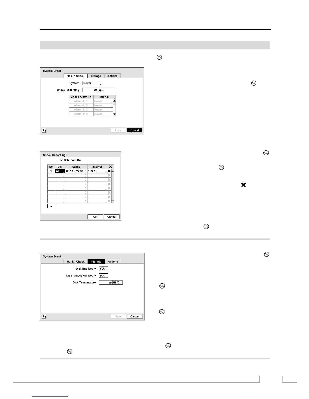
Digital Video Recorder
39
System Event
Highlight System Event in the Event menu and press the
button. The System Event setup screen appears.
Figure 54 — Health Check screen
The DVR can be configured to run self-diagnostics and report
the results.
Highlighting the box beside System and pressing the button
allows you to select the interval that you want the DVR to run
self-diagnostics on the system. You can select from 1 hr. to
30 days or Never.
Highlight the Setup... box beside Check Recording and press the
button. The Check Recording screen appears.
Highlighting Schedule On and pressing the button toggles On and
Off. When set to On, you can select the day, time range and interval that
you want the DVR to run self-diagnostics on the recorder. The Interval
can be selectable from 1 min. to 7 days or Never. The
box allows
you to delete a check recording schedule.
Highlighting the box under the Interval heading beside each alarm-in and pressing the button allows you to change the
interval that you want the DVR to run self-diagnostics on Alarm Inputs. You can select from 1 hr. to 30 days or Never.
Highlight the Storage tab, and the Storage screen displays.
Figure 55 — Storage screen.
Highlight the box beside Disk Bad Notify, and press the
button. Select percentage level of bad disk sectors at which
you want the DVR to trigger an alert. Percentage levels range
from 10% to 90%.
Highlight the box beside Disk Almost Full Notify, and press
the
button. Select the percentage level of disk usage at
which you want the DVR to trigger an alert. Percentage levels
range from 80% to 99%.
Highlight the first box beside Disk Temperature, and press
the
button. Use the Up and Down arrow buttons to scroll
through the numbers. Refer to the hard disk drive manufacturer’s
documentation for the correct temperature setting. If the
temperature of hard disk drive exceeds the defined threshold,
the system triggers an alert.
Highlight the second box beside Disk Temperature, and press the
button. Select either ºC (Celsius) or ºF (Fahrenheit),
and press the
button.
Page 48
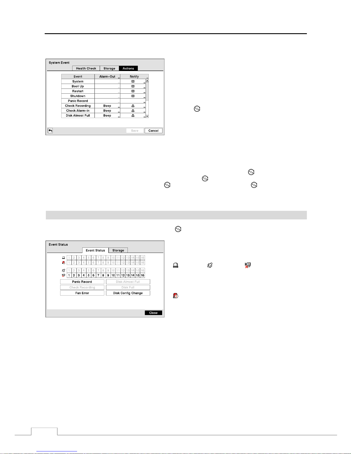
User’s Manual
40
Highlight the Actions tab, and the System Event Actions screen displays.
Figure 56 — System Event Actions screen
The DVR can be set to react to system events. System events
can be associated with an Alarm-Out connector, sound the
DVR’s internal buzzer, and/or notify a number of different
devices.
Highlight the Alarm-Out box beside the desired event (Check
Recording, Check Alarm-In, Disk Almost Full, Disk Full,
Disk Bad, Disk Temperature, or Disk S.M.A.R.T.), and
press the
button. A list of Alarm Outputs appears. You
can associate as man y Alarm-Outs with the Event as you wish.
If the DVR detects that event, it triggers output signals on all
the associated Alarm-Out connectors. You can also have the
DVR’s internal buzzer sound if an event is detected
.
NOTE: Alarm-Out action cannot be set to System, Boot Up, Restart, Shutdown and Panic Record events.
Highlight the Notify box beside the desired event (System, Panic Record, Check Recording, Check Alarm-In, Disk
Almost Full, Disk Full, Disk Bad, Disk Temperature, or Disk S.M.A.R.T.), and press the
button. You can toggle
the entire list On and Off by highlighting Notification and pressing the
button. You can toggle the individual items
On and Off by highlighting that item and pressing the
button. Highlight OK and press the
button to accept your
changes.
NOTE: For the Notify action to work, the DVR sho uld b e regi stered in the RAS (R emote A dminis tration System ).
Event Status
Highlight Event Status in the Event menu and press the
button. The Event Status screen appears.
Figure 57 — Event Status screen.
The Event Status screen displays the status of the DVR’s
systems and inputs. Events will be highlighted, and related
channels or events will flicker for five seconds when detected.
(
Alarm-In),
(Motion) and (Video Loss) will be
highlighted when each event is detected based on the settings
you made in the Alarm-In, Motion Detection and Video Loss
setup screen on the Event menu.
(Check Alarm-In) and Check Recording will be
highlighted when each event is detected based on the settings
you made in the System Even t setup screen on the Event menu.
Panic Record will be highlighted while the DVR is in the
panic recording mode.
Disk Almost Full will be highlighted when the DVR is not in the Recycle mode and the level of disk usage reaches
the Disk Almost Full percentage you made in the System Event setup screen on the Event menu. Disk Full will be
highlighted when the DVR is not in the Recycle mode and all available storage space has been used. Disk Config
Change will be highlighted when the DVR reboots after the hard disk drive has been replaced.
Fan Error will be highlighted when the cooling fan to the left of the power cord on the rear panel is not working for
more than four seconds.
Highlighting the Storage tab will display the hard disk drive status. Refer to the Storage section for details.
Page 49
Digital Video Recorder
41
Chapter 4 — Operation
NOTE: This chapter assumes your DVR has been installed and conf igured. If it has not, plea se refer to Chap ters
2 and 3.
The DVR’s controls are similar to a VCR. As with a VCR, the main functions are recording and playing back video.
However, you have much greater control over recording and playing back video. You can establish recording schedules
based on time of day and day of the week. The DVR allows you to search through the recorded video using much more
sophisticated tools than those available with VCRs. Additional DVR features that are not available with VCRs are
remote control and viewing, and recording video at the same time you are watching previously recorded video.
The front panel controls are described in Chapter 3 — Configuration.
Turning on the Power
Once you have installed the DVR following the instructions in Chapter 2 — Installation, it is ready to record.
Live Monitoring
As soon as the DVR completes its initialization process, it will begin showing live video on the attached monitor and
playing live audio through the attached speaker. The default mode is to display all cameras at once. Pressing any camera
button will cause that camera to display full screen. It displays live video and plays live audio until the user enters
another mode.
While in the live monitoring mode, press the
MENU button displays the following Live Monitoring menu at the top of
the screen. Pressing the MENU button again hides the menu. You can navigate through menus and items by pressing
the arrow buttons.
Freeze
Sequence
Camera Menu
Alarm
Panic
Setup
Search Mode
Login/Logout
Figure 58 — Live Monitoring menu.
NOTE: The Live Monitoring menu also can be displayed by moving the mouse pointer to the top of the screen.
Page 50
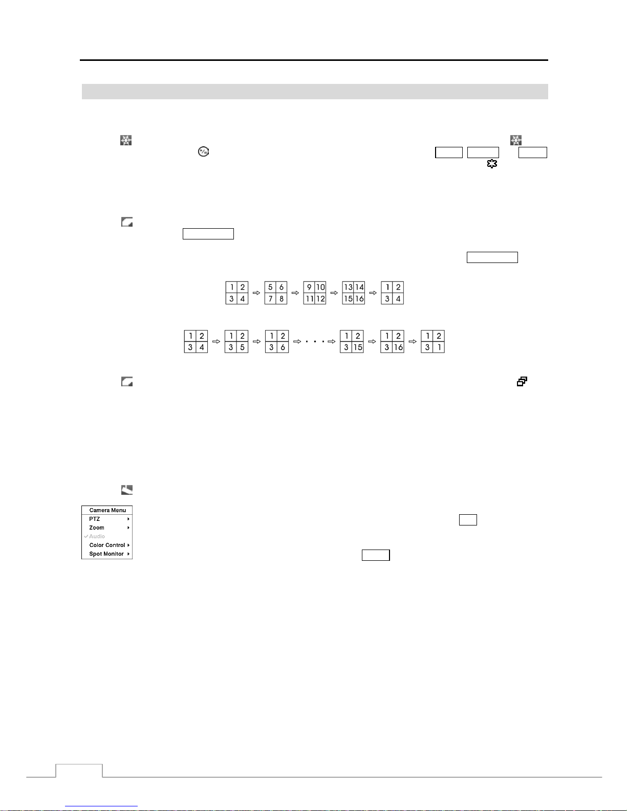
User’s Manual
42
Live Monitoring Menu
Freeze
Selecting
(Freeze) in the Live Monitoring menu will freeze the current image on the screen until you select again.
It is the same as pressing th e (Play/Pause) button. Pressing any button except for the MENU, ALARM and PANIC
buttons while in the Freeze mode can also exit the Freeze mode. While in the Freeze mode, the icon displays in
bottom-left corner if Freeze is selected in the Display setup screen (OSD tab).
Sequence
Selecting
(Sequence) in the Live Monitoring menu causes the cameras to display sequentially. It is the same as
pressing and holding the SEQUENCE button for three seconds or longer. When in one of the multi-view formats,
pressing this button will cause the DVR to go through predefined screen layouts (Full Sequence). Or, the bottom, right
screen will display live cameras sequentially (Cameo Sequence). For example, if you press the SEQUENCE button
in the 2x2 format, the DVR changes pages as follows:
< Full Sequence >
< Cameo Sequence >
Selecting again in the Live Monitoring menu exits the Sequence mode. While in the Sequ ence m ode, the icon
displays in bottom-left corner if Sequence is selected in the Display setup screen (OSD tab). If all the cameras in a page
are Off, or have lost video or are set to Covert (unless the user has authority to view covert cameras), that page will be
excluded from the sequence.
NOTE: The Full Sequence for the full sequence monitoring and the Cameo Sequence for the cameo sequence
monitoring should be selected in the Display setup screen (Main Monitor tab).
Camera Menu
Selecting
(Camera Menu) in the Live Monitoring menu displays the following Camera Menu.
Audio: Selecting Audio toggles audio output On and Off.
Color Control: Selecting Color Control and choosing the camera number allows you to control brightness, contrast,
hue and saturation for each camera for the sel ected cam era if a user who has Color Control authorit y logs into the
system. It is the same as pressing and holding a camera button for a few seconds.
NOTE: It is important that c ameras and monit ors ar e co rre ctly in stal led and ad justed p rior to m aking any image
adjustments using the DVR’s controls.
Any image adjustments you make will be applied to both the live video on the monitors and the recorded
video.
Spot Monitor: Selecting Spot Monitor allows you to select the camera you want to display on a Spot monitor. Refer
to the following Spot Monitoring section for details.
NOTE: The Camera Menu also can be displayed by clicking the right mouse button on the screen while in the
live monitoring mode.
PTZ: Selecting PTZ and choosing the camera number allows you to control the selected camera as
long as it has Pan, Tilt and Zoom capabilities. It is the same as pressing the
PTZ button. Refer to
the following PTZ Mode section for details.
Zoom: Selecting Zoom and choosing the camera number zooms the current im age of th e sel ected
camera on the screen. It is the same as pressing the
ZOOM button. Selecting Zoom again in the
Camera Menu again exits the Zoom mode. Refer to the following Zoom Mode section for details.
Page 51
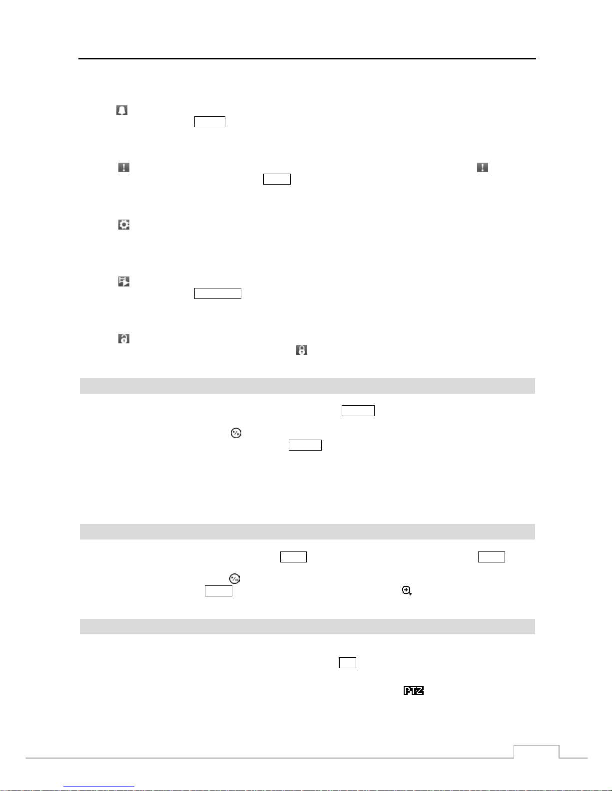
Digital Video Recorder
43
Alarm
Selecting
(Alarm) in the Live Monitoring menu resets the DVR’s outputs including the internal buzzer during an alarm.
It is the same as pressing the ALARM button.
Panic
Selecting
(Panic) in the Live Monitoring menu s tarts pani c recording of all cam eras , and selecting again stops
panic recording. It is the same as pressing the PANIC button.
Setup
Selecting
(Setup) in the Live Monitoring menu enters the Main Setup screen. Refer to Chapter 3 ─ Configuration
for detailed descriptions of system setup.
Search Mode
Selecting
(Search Mode) in the Live Monitoring menu exits the live monitoring mode and enters the sear ch mode.
It is the same as pressing the
PLAYBACK button.
Login/Logout
Selecting
(Login) in the Live Monitoring menu accesses the Login screen, and you will be asked to select a User
and enter the password to log into the system. Selecting
(Logout) in the Live Monitoring menu displays the Logout
screen asking you to confirm whether or not you want to log out the current user.
Active Cameo Mode
You can enter the Active Cameo mode by pressing and holding the
CAMEO button for three seconds or longer in any
multi-view format. The yellow outline surrounding the video indicates the active cameo, and pressing the arrow buttons
moves the active cameo. Pressing the (Play/Pause) button exits the Active Cameo mode. Selecting Exit Group
Edit in the cameo menu displayed when pressing the
CAMEO button also exits the Active Cameo mode. The active
cameo mode will remains in effect for 15 seconds if there is no further operation.
In active cameo mode, press the button for the camera you want to display in the active cameo. After setting the camera
number to active cameo, the DVR moves the active cameo to the next cameo. W hen the camera num ber exists on the
current screen, the active cameo is changed with the existing camera number. When the camera number does not exist
on the current screen, the active cameo is replaced by the camera number. You can change the screen layout in this way.
Zoom Mode
You can enlarge an area of the video by pressing the
ZOOM button. For a few seconds after pressing the ZOOM button,
a rectangle displays on the screen. A rectangle shows the area that will be enlarged. You can move the rectangle around
using the arrow buttons. Pressing the
(Play/Pause) button in the Zoom mode enlarges the area in rectangle. Exit
the Zoom mode by pressing the
ZOOM button. While in the Zoom mode, the icon displays if Zoom is selected in
the Display setup screen (OSD tab).
PTZ Mode
If a user who has PTZ Control authority logs into the system, the user can control PTZ cameras. The DVR will control
cameras with Pan, Tilt and Zoom capabilities. Press and hold the
PTZ button for three seconds or longer to display
the PTZ camera menu and enter the PTZ mode, and press the button again to exit the PTZ mode.
Select the PTZ camera you wish to control by selecting it from the menu. The icon
displays on the PTZ camera
screen.
Page 52
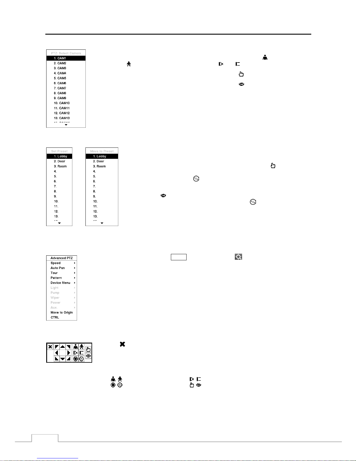
User’s Manual
44
To use the front panel buttons, press the Left and Right arrow buttons to pan left and right. Press
the Up and Down arrow buttons to tilt the camera up and down. Press the
button to zoom in,
and press the
button to zoom out. You can use the
and buttons to focus the image.
You can establish preset positions for PTZ cameras. Press the to establish Presets.
You can quickly move PTZ cameras to Preset positions. Press the to view an established cam era
Preset position.
Figure 59 — PTZ Select Camera menu.
You can save camera position settings as “presets” so that you can go directly
to desired views.
Once you have the camera at the desired settings, press the
button, and the
Set Preset dialog box will appear. Select the number you want to assign to
the preset and press the
(Play/Pause) button. Use the virtual keyboard to
enter the preset name.
Press the button to load the PTZ preset and the Move to Preset dialog box
will appear. Select th e desired preset and press the
button to load the preset.
< Set Preset > < Move to Preset >
Figure 60 — PTZ Preset menu.
While in the PTZ mode, pressing the MENU button and selecting (Advanced PTZ) in the menu
displaying at the top of the screen displays the Advanced PTZ menu.
Set the feature you wish to control by selecting it from the menu. Refer to the camera manufacturer’s
instructions for the proper settings. Depending on the camera specifications, some features may not
be supported.
NOTE: The Pan/Tilt speed can be controlled by using the mouse. While in the PTZ mode, clicking
the left mouse button on th e im age and dragging the mouse in the pan/tilt direction you
want to move and then select the speed.
You can use a mouse for convenient PTZ control. Position the mouse pointer at the bottom of the screen, and the
following PTZ toolbar will display.
Clicking
on the left side exits the toolbar. If you want to display the toolbar again, position
the mouse pointer at the bottom of the screen. Change the toolbar location by clicking the empty
space on the left side of the toolbar and drag it to where you want it located on the screen. Use
the arrow buttons on the toolbar to pan or tilt the camera in the direction you want. The other
controls on the toolbar perform as described below:
Zoom In / Out Focus Near / Far
Iris Open / Close Set / Load Preset
Page 53
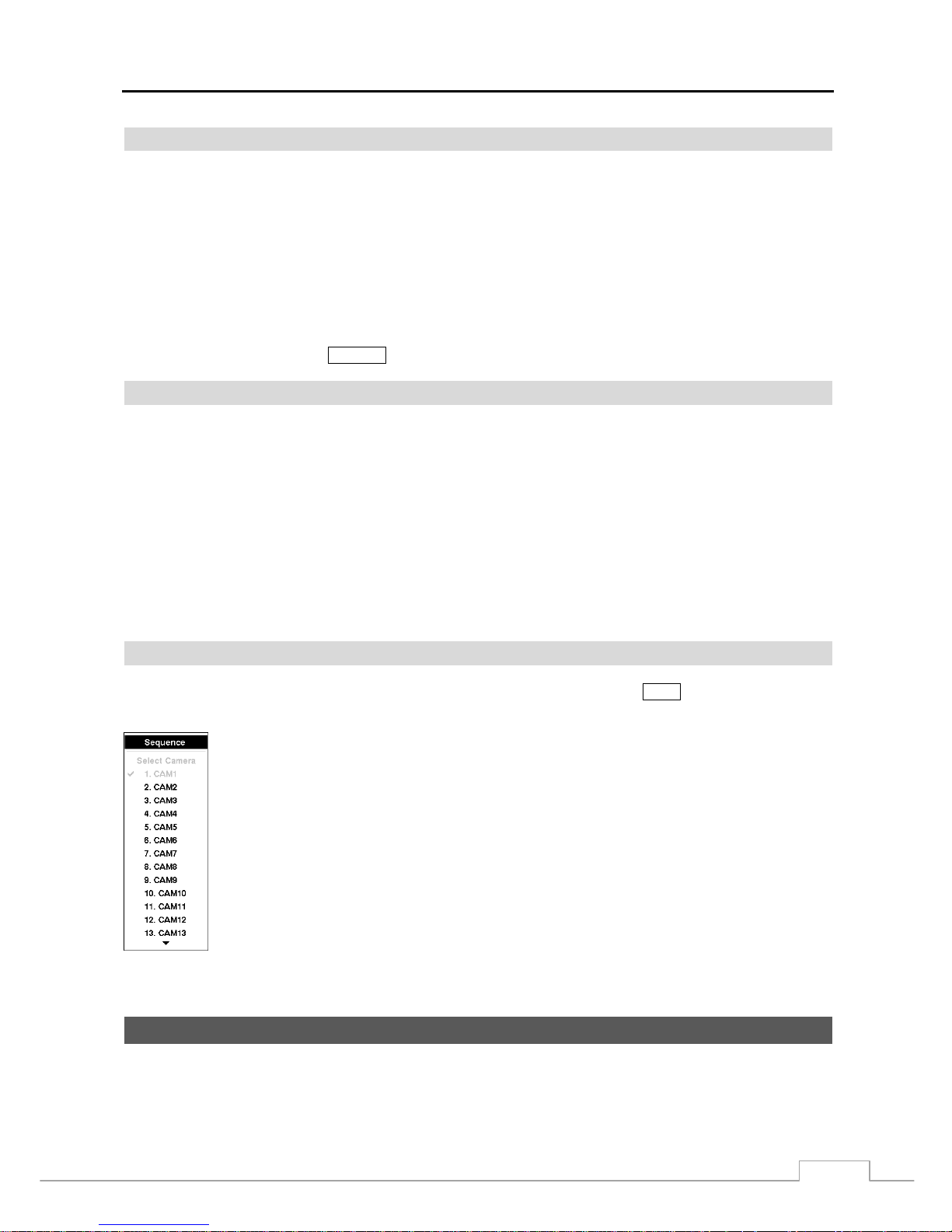
Digital Video Recorder
45
Event Monitoring
When an event occurs, the DVR will display the camera associated with the event if Event Monitoring On is selected in
the Display setup screen (Main Monitor tab).
How the cameras are displayed depends on the number of cameras associated with the event. If one camera is associated
with the event, the DVR will display the cam era full screen. If tw o to four camera s are associa ted with the ev ent, t he
DVR will display the cameras on a 2x2 screen. If five to nine cameras are associated with the event, the DVR will
display the cameras on a 1+5, 1+ 7 or 3x3 screen. If 10 or more ca meras are associated with the event, the DVR will
display the cameras on a 4x4 screen.
Event monitoring lasts for the dwell time set for event recording. After the dwell time has elapsed, the monitor returns
to the previous screen unless another event has occurred. If you want to return to the liv e monitoring mode before the
dwell time has elapsed, press the
DISPLAY button or one of the camera buttons.
Covert Camera
If a camera is set up as Covert 1 in the Camera setup s creen (Settin gs tab), that camera will not be di splayed unles s a
user with Covert Camera View authority logs into the system. However the camera title and status icons will be
displayed on the monitor.
If a camera is set up as Covert 2 in the Camera setup screen (Settings tab), that camera appears to be Off unless a use r
with Covert Camera View authority logs into the system. The camera title will be grayed out and status icons will
not be displayed on the monitor.
NOTE: When a camera is set up as Covert 1, the DVR displays the camera title and status icons on the covert
video. When set up as Covert 2, the DVR displays only the camera title on the covert video.
If a user who has Covert Camera View authority logs into the system, the user can view video fro m cameras set to
Covert 1 or Covert 2 including the camera titles and status icons.
Spot Monitoring
You can select the camera you want to disp lay on a Spot Monitor . Press and hold the SPOT button for three seconds
or longer displays the Sequence Menu.
Select the camera to be displayed on the Spot Monitor. Selecting Sequence from the menu displays
more than one camera on a Spot Monitor sequentially. Select Sequence again to stop sequencing on
the Spot Monitor. Any cameras that are Off, have lost video or are set to Covert (unless the user has
authority to view covert cameras) will b e excluded from the sequence. W hen the Spot Monitor is in
the sequence mode, you can set the camera’s display dwell time. Refer to Chapter 3 – Configuration –
Display Screen section for details.
Figure 61 — Sequence menu.
Using a Mouse
You can use a mouse instead of the front panel buttons to perform many of the DVR functions. In the Live Monitoring
mode or Search mode, moving the mouse pointer to the left edge of the screen displays the following Mouse Display menu.
Page 54
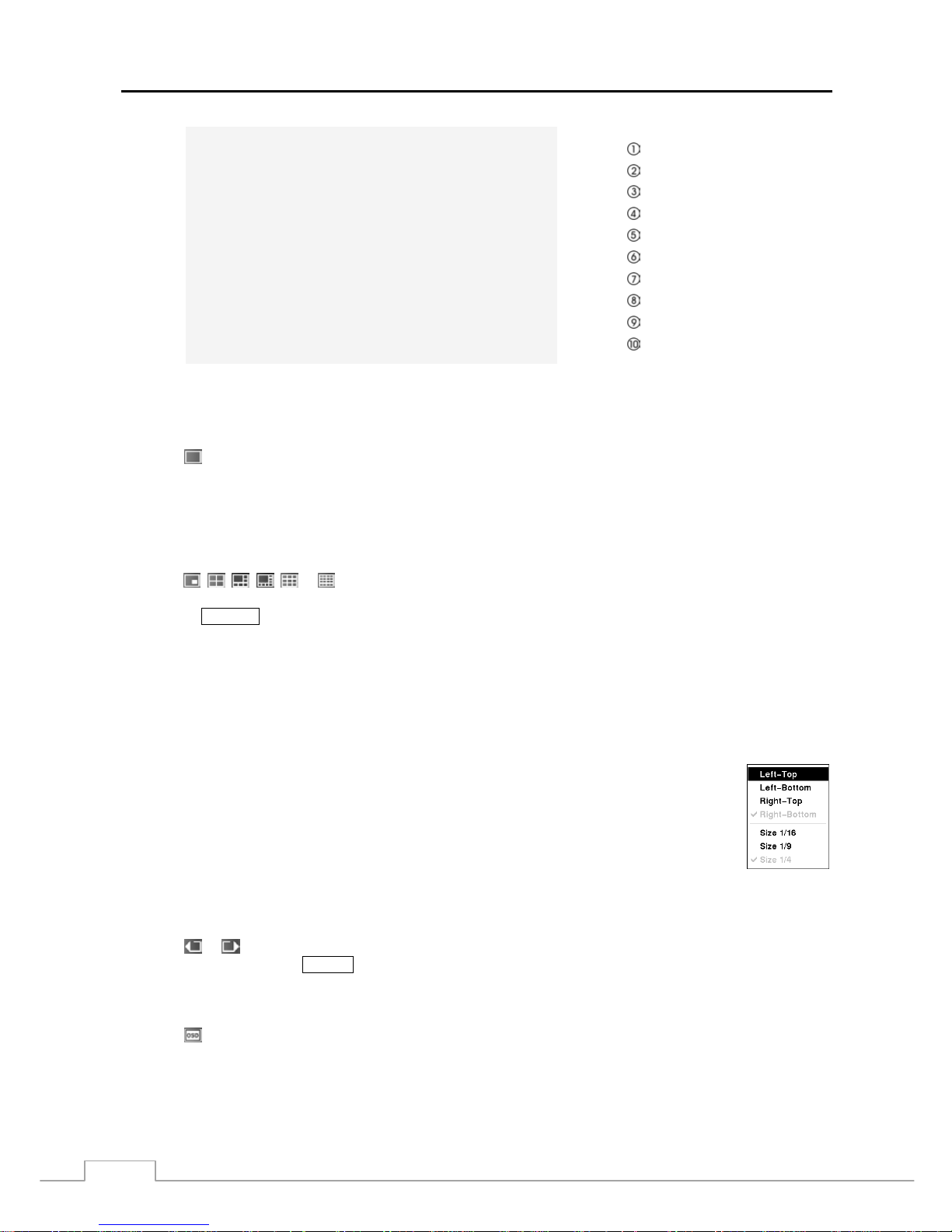
User’s Manual
46
Full Screen
PIP
2x2
1+5
1+7
3x3
4x4
Previous Group
Next Group
OSD
Figure 62 — Mouse Display menu.
Full Screen
Selecting
(Full Screen) in the Mouse Display menu and choosing the camera number button displays the sel ected
camera full screen. It is the same as pressing the individual camera buttons on the front panel or clicking the left mouse
button on a camera image when in one of the multiview formats (i.e., 2x2, 1+5, 1+7, 3x3 or 4x4). Clicking the left mouse
button on the screen again returns to the previous display mode.
PIP, 2x2, 1+5, 1+7, 3x3, 4x4
Selecting
, , , , or (PIP, 2x2, 1+5, 1+7, 3x3 or 4x4) in the Mouse Display menu displays the cameras
in the selected multiview screen mode (PIP, 2x2, 1+5, 1+7, 3x3 or 4x4). Select ing each d ispla y mode is the s ame as
pressing the
DISPLAY button or scrolling the mouse wheel up and down when in one of the multiview formats (i.e.,
2x2, 1+5, 1+7, 3x3 or 4x4).
NOTE: The PIP, 1+5, and 1+7 display modes will not be supported in the search mode.
In the 1+5 or 1+7 display mode, the main channel indicates the channel of the big screen which is displayed
in the top-left and you can select the camera you want to display on the main channel screen. Select a
channel on the screen and click the right mouse button to display the Camera Menu. Selecting Go To
Main swaps the selected channel with the main channel. This function is supported only in the 1+5 or
1+7 display mode and in the other channels except the main channel.
You can change the location of the PIP (Picture-in-Picture) counterclockwise or clockwise by pressing
the Up and Down arrow buttons and change its size by pressing the Left and Right arrow buttons. To
change its location and size by using the mouse, select the PIP and then click the right mouse button to
display the following menu. Select the options you want. You can also change the location of the PIP
by clicking the left mouse button on the PIP window and dragging it to where you want it located, and
change the size of the PIP b y clicking the left m ouse button at the corn er of th e PIP wind ow and drag ging
it until it is the desired size.
Previous Group, Next Group
Selecting
or (Previous Group or Next Group) in the Mouse Display menu moves to the previous or next page.
It is the same as pressing the
GROUP button.
OSD
Selecting
(OSD) in the Mouse Display menu toggles OSD On and Off.
Page 55
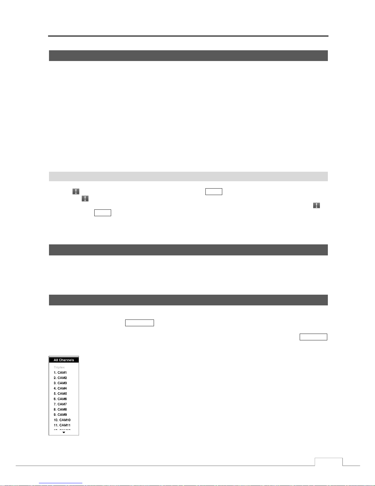
Digital Video Recorder
47
Recording Video
Once you have installed the DVR following the instructions in Chapter 2 — Installation, it is ready to record. The DVR
will start recording based on the settings you made in the Record setup screen. See Chapter3 — Configuration.
Recycle On or Recycle Off. The factory default is Re cycle On. It does this by recording over the oldest video once
the hard disk is full. Setting the DVR to Recycle Off causes it to stop recording once the hard disk is full.
Standard (CIF), High (Half D1) or Very High (D1). The factor y default reso lution is Standard . When set to Standard,
the DVR has a maximum recording speed of 480 ips (240 ips for 8-channel model). When set to High, the DVR has a
maximum recording speed of 240 ips (120 ips for 8-channel model). When set to Very High, the DVR has a maximum
recording speed of 120 ips (60 ips for 8-channel model).
Although you will be able to record without changing the unit from its original facto ry settings, you will want to take
advantages of the DVR’s many tools. See Chapter 3 — Configuration for detailed descriptions of the recording mode
options.
Panic Recording
Selecting
(Panic) in the Live Monitoring menu or pressing the PANIC button starts panic recording of all cameras,
and selecting or pressing the button again stops panic recording. If you set the Panic Recording Duration in the
Panic Record setup screen, panic recording will stop automatically according to the preset duration as long as
is
not selected or the
PANIC button is not pressed.
NOTE: When the DVR is not in the Recycle mode and all available storage space has b een used, panic reco rding
will not operate.
Recording Audio
If the DVR was set up to record audio, it will record audio from up to four inputs when video is recording.
NOTE: Make certain you comply with all local and federal laws and regulations when recording audio.
Playing Recorded Video
If a user who has Search authority logs into the system, the user can view recorded image. Once video has been recorded,
you can view it by pressing the
PLAYBACK button.
The DVR supports the Triplex function: monitoring, record ing and p laying back at the s ame time. Pressing the PLAYBACK
button when in one of the multi-view formats enters the Triplex mode and displays the Select Playback Camera menu.
Selecting All Channels plays back video of all cameras. The DVR maintains the same display format
as it does in the live mode except for the PIP format. You can also change the screen layout in the same
way as you do in the live mode.
Selecting the camera number under Tr iplex enters the Triplex mode and plays back video of the selected
camera. When in the single-screen dis p lay format, the camera currently dis p la yed on the screen will
be selected and when in the PIP display format, the camera displayed on the PIP screen will be selected
for the search channel. During the Triplex mode, the DVR maintains the same display format as it does
in the live mode. A red outline surrounding the video and the camera title indicates the search channel.
While in the Triplex Mode, the DVR continu es recording cameras as they were set up in the r ecording
schedule. Also, live monitoring will continue except for the camera that has been selected for playback.
Figure 63 — Select Playback Camera menu.
Page 56
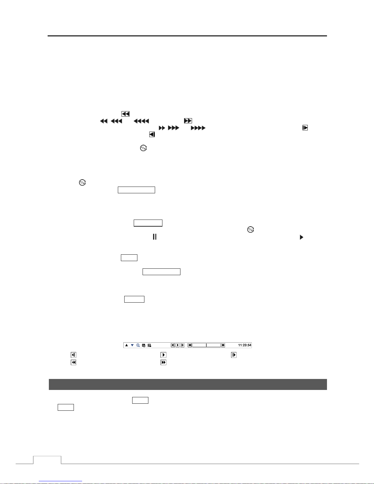
User’s Manual
48
When playing video for the first time, the DVR will display th e most recent image. When playing video subsequent
times, the DVR will start playing video from the last recalled image. Recorded audio will be played when the DVR
displays a camera with recorded audio in full screen mode.
NOTE: Only the administrator and use rs with Cove rt Camera View author ity can v iew video f rom covert cameras.
The covert cameras in the playback mode are determined by the current camera settings.
Camera Buttons (1 to 16): Pressing the individual camera buttons will cause the selected camera to display full screen.
Arrow Buttons: Pressing the
button plays video backward at high speed. Pressing the button again toggles the
playback speed from
, and . Pressing the button plays video forward at high speed. Pressing the
button again toggles the playback speed from
, and . When in the pause mode, pressing the button
moves to the next image and pressing the
button moves to the previous image.
PLAY/PAUSE Button: Pressing the
button plays back images at regular speed or pauses playing video.
CAMEO Button: Pressing and holding the button for three seconds or longer enters the cameo mode. The yellow
outline surrounding the video indicates the active cameo, and pressing the arrow buttons moves the active cameo.
Pressing the desired camera button in the active cameo edits the cameo and displays the video of selected camera.
Pressing the
(Play/Pause) button exits the Active Cameo mode. Selecting Exit Group Edit in the cameo menu
displayed when pressing the MENU/CAMEO button also exits the Active Cameo mode.
NOTE: A cameo is defined a s any cell within multi-scre en d isplay. The cameo mode allows you to change the
screen layout by editing the cameo.
PLAYBACK Button: Pressing the
PLAYBACK button enters the playback mode, and pressing the button again exits
the playback mode. When entering the playback mode, video is paused. Pressing the (Play/Pause) button plays back
video at regular speed. The screen displays
when the DVR is in the Pause mode and the screen displays when the
DVR is playing back video.
ZOOM Button: Pressing the
ZOOM button zooms in the current image on the screen.
DISPLAY/SPOT Button: Pressing the
DISPLAY/SPOT button toggles different display formats. The available formats
are: 2x2, 3x3 and 4x4. Pressing and holding the button for three seconds or longer allows you to select which cameras
will display on the Spot monitor.
GROUP Button: Pressing the
GROUP button changes the screen from the current camera group to the next camera
group, and the screen displays page number.
You can use a mouse for convenient playback control. Position the mouse pointer on the playback screen, and the
following Record Table Search (Compact View Mode) screen will display. The individual controls on the toolbar
perform the following functions as described below:
Go to the previous image Play/Pause Go to the next image
Fast backward play Fast forward play
Searching Video
While in the search mode, press the
MENU button displays the following Search menu at the top of the screen. Pressing
the MENU button again hides the menu. You can navigate through menus and items by pressing the arrow buttons.
Page 57
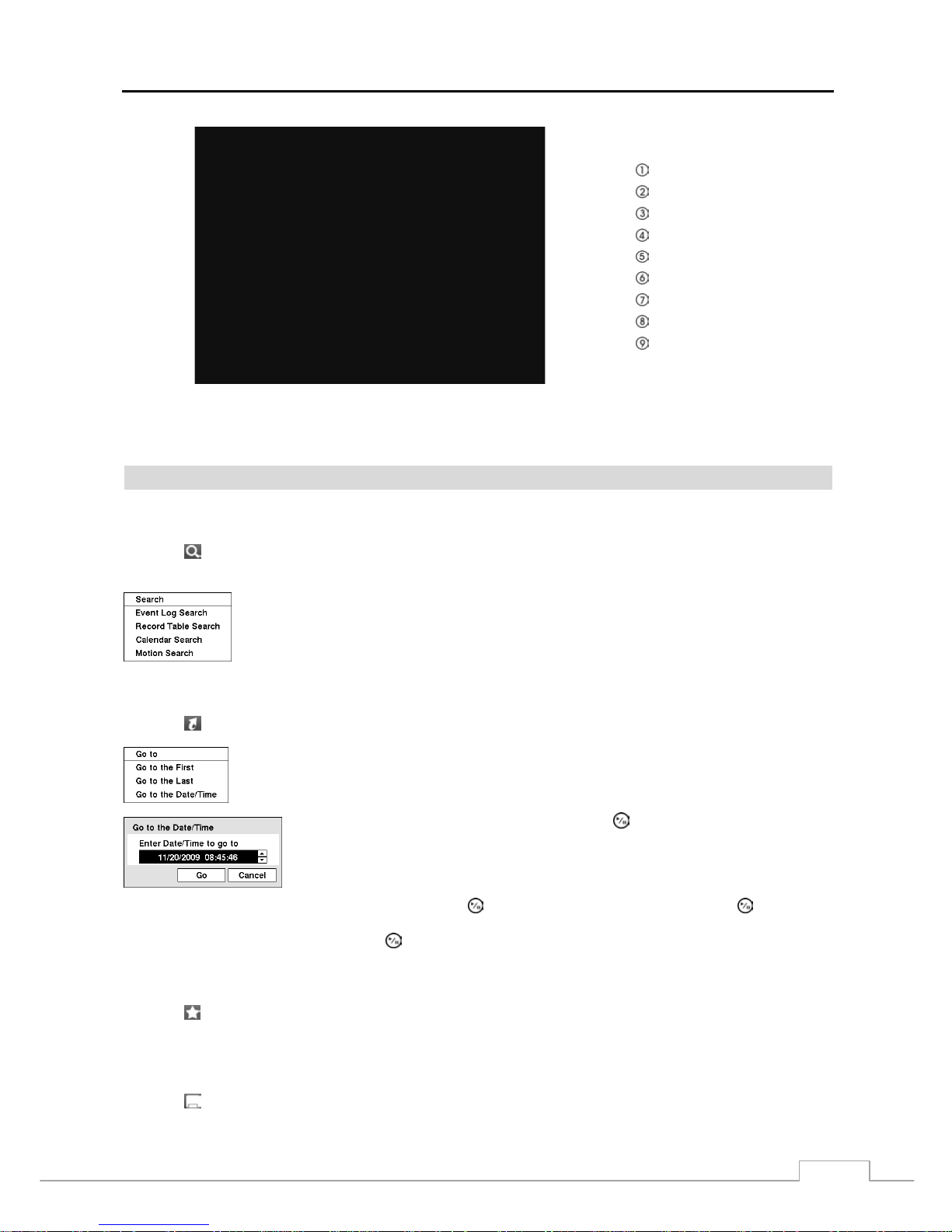
Digital Video Recorder
49
Search
Go To
Bookmark
Export
Camera Menu
Alarm
Panic
Data Source
Exit
Figure 64 — Search menu.
NOTE: The Search menu also can be displayed by moving the mouse pointer to the top of the screen.
Search Menu
Search
Selecting
(Search) in the Search menu displays the following Search menu. See the following Event Log Search,
Record Table Search, Calendar Search and Motion Search sections for details.
Event Log Search: Selecting Event Log Search selects video from the event log.
Record Table Search: Selecting Record Table Search selects using a recording table.
Calendar Search: Selecting Calendar Search selects using a calendar.
Motion Search: Selecting Motion Search selects motion events.
Go To
Selecting
(Go To) in the Search menu displays the following Go to menu.
Go to the First: Selecting Go to the First displays the first recorded image.
Go to the Last: Selecting Go to the Last displays the last recorded image.
Go to the Date/Time: Selecting Go to the Date/Time displays the Go to the Date/Time screen.
Move the cursor over the date and time and press the (Play/Pause) button. You can use
the Left and Right arrow buttons to highlight the year, month, day, hours, minutes and
seconds. Use the Up and Down arrow buttons to change to the date and time you want
to search for video.
Once you have set the date and time you want, press the button. Then highlight Go and press the button. The
selected date and time will display. (If no video was recorded during the selected time, a message appears alerting you
that no image was recorded at that time.) The
button and arrow buttons can now be used to review the surrounding video.
Bookmark
Selecting
(Bookmark) in the Search menu adds the current playback point to the bookmark list. See the following
Bookmarks section for details.
Export
Selecting
(Export) in the Search menu displays the following Export menu. See the following Clip Copy section
for details.
Page 58
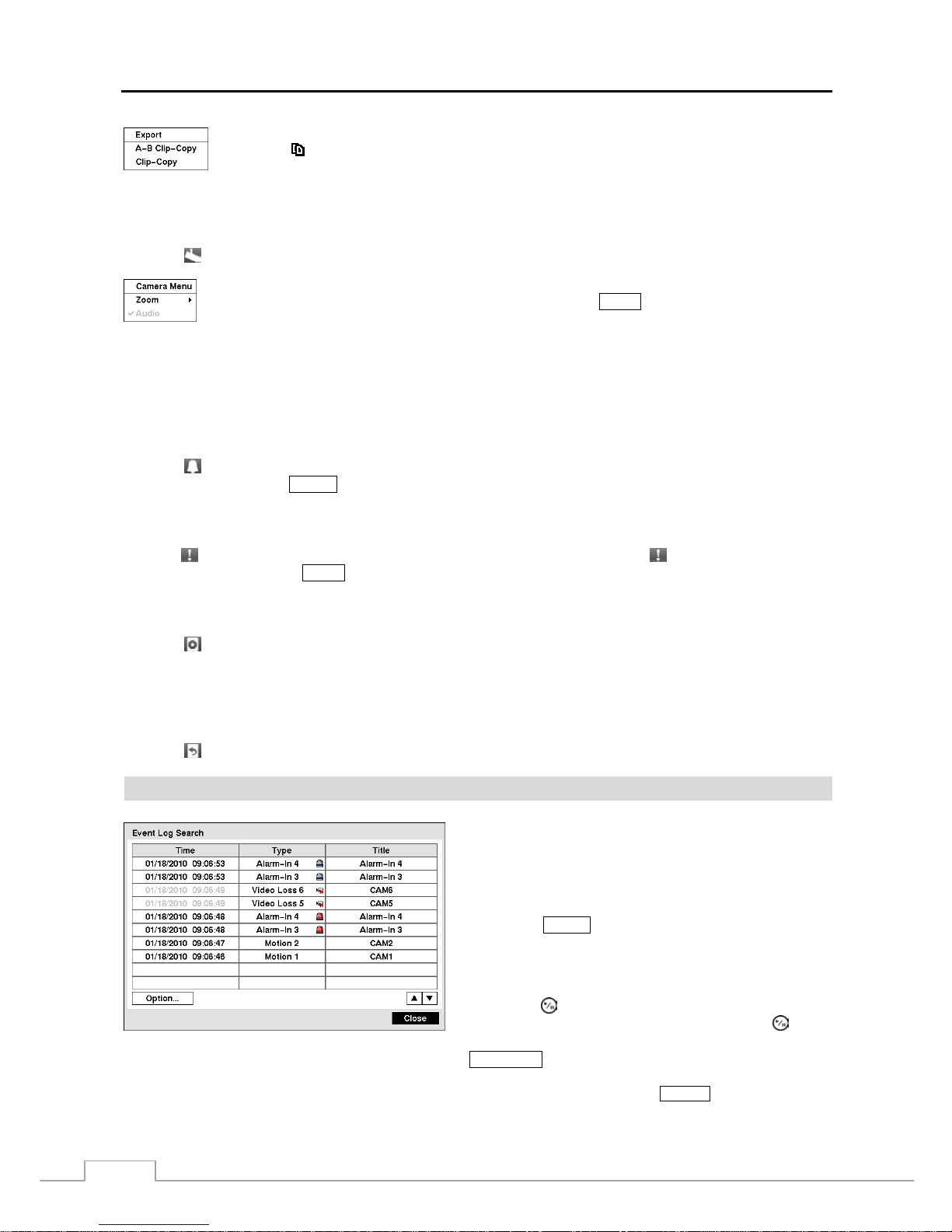
User’s Manual
50
A–B Clip-Copy: Selecting A–B Clip-Copy will set the starting point of the video to be clip copied,
and the
icon displays at the bottom-left corner of the screen. Selecting A–B Clip-Copy again
will set the ending point of the video to be clip copied and displays the Clip-Copy screen.
Clip-Copy: Select Clip-Copy, and the Clip-Copy screen appears to allow clip copy setup.
Camera Menu
Selecting
(Camera Menu) in the Search menu displays the following Camera Menu.
NOTE: The Camera Menu also can be displayed by clicking the right mouse button on the screen while in the
search mode.
Alarm
Selecting
(Alarm) in the Search menu resets the DVR’s outputs including the internal buzzer during an alarm. It
is the same as pressing the ALARM button.
Panic
Selecting
(Panic) in the Search menu starts panic recording of all cameras, and selecting again stops panic recording.
It is the same as pressing the PANIC button.
Data Source
Selecting (Data Source) in the Search menu allows you to select the data source to be searched. Selecting Record
searches recorded data on primary storage installed in the DVR, and selecting Other searches recorded data on storage
used for another DVR then installed in this DVR.
Exit
Selecting
(Exit) in the Search menu exits the search mode and enters the live monitoring mode.
Event Log Search
Figure 65 — Event Log Search screen.
The DVR maintains a log of each time the Alarm Input port
is activated. The Event Log Search screen displays this list.
Use the arrow buttons to highlight the event for which you
would like to see video.
The Event Log Search screen can also be accessed by
pressing the ALARM button unless there is an alarm. There is
no determined user authority to display the Event Log Search
screen, however, the event video will not be pl ayed unless a
user with Search authority logs into the system
.
Pressing the (Play/Pause) button will extract the event video
and display the fir st image of the ev ent. Pressing the
button
will start playing the “event” video segment. Pressing
PLAYBACK returns to live monitoring.
NOTE:
It is possible that no recorded image displays on the current screen. Press the
DISPLAY button and change
the screen mode to 4x4. You will be able to easily see the camera have recorded video during target
time.
Zoom: Selecting Zoom and choosing the camera number zooms the current playback im age of the
selected camera on the screen. It is the s ame as pr essing the
ZOOM button. Selecting Zoom again
exits the Zoom mode.
Audio: Selecting Audio toggles audio playback On and Off. Recorded audio will be p layed when
the DVR displays a camera with recorded audio in full screen mode.
Page 59
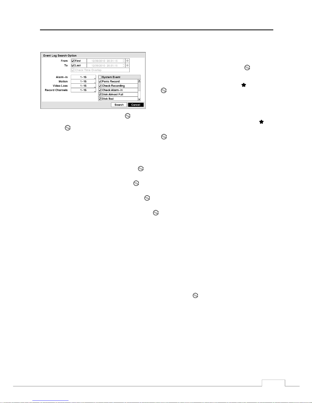
Digital Video Recorder
51
You can also narrow your event search by selecting the Option… button and setting up the new search condition.
You can search video from the first to last recorded images ,
or you can set the start and stop times and dates.
Highlight the box beside From and press the
button to
toggle between On and Off. When set to Off, you can enter a
specific Date and Time. W hen set to On, the search will be from
the first recorded image. When highlighting
and pressing
the
button the bookmark list displays and the bookmark
point you selected will be the starting date and time.
Highlight the box beside To and press the
button to toggle between On and Off. When set to Off, you can enter a
specific Date and Time. When set to On, the sear ch will be from the l ast recorded i mage
.
When highlighting
and
pressing the button the bookmark list displays and the bookmark point you selected will be the ending date and time.
Highlight the box beside Check Time Overlap and press the
button. It toggles between On and Off. You will only
be able to turn the Check Time Overlap on or off if a user-defined date and tim e is set to From and To. If the DVR’ s
date and time have been reset, i t is possible for the DVR to have more than one overlapping start and stop time. When
set to On, you will be asked to select one of the overlapping start and stop time. When set to Off, the DVR will display
search results from all start times to all stop times.
Highlight the box beside Alarm-In and press the
button. You can select the alarm inputs that you want to include
in your search.
Highlight the box beside Motion and press the
button. You can select the cameras for which you want any reports
of motion detection.
Highlight the box beside Video Loss and press the
button. You can select the cameras for which you want any
reports of lost video.
Highlight the box beside Record Channels and press the
button. You can s elect the ca meras that you want to se arch
for any reports of event recorded data. The DVR will displa y the events (not the ca mera channels) t hat occurred and
that also are recorded on the camera channel that you selected. If you do not select a camera ch annel in this field, the
DVR will search events that are not associated with cameras.
You can also toggle On and Off self-diagnostic System Events as part of your search. The choices are:
Panic Record
Check Recording
Check Alarm-In
Disk Almost Full
Disk Bad
Disk Temperature
Disk S.M.A.R.T.
Fan Error
Disk Config Change
Once you set your desired search conditions, highlight Search and press the
button to display the search results in
the Event Log Search screen. Selecting Cancel exits the screen without saving the changes.
Page 60
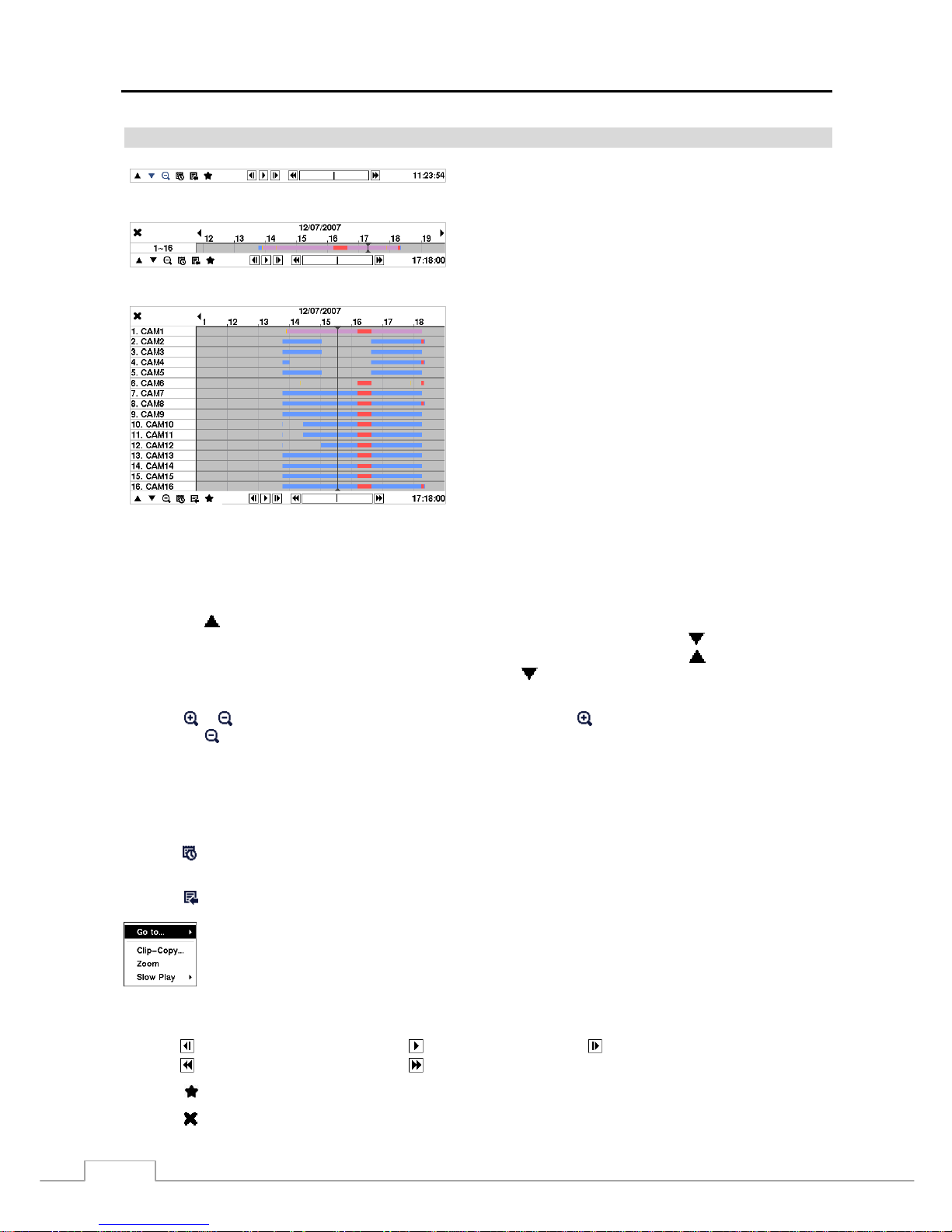
User’s Manual
52
Record Table Search
< Compact View >
< Standard View >
< Expanded View >
Figure 66 — Record Table Search screen.
Recording informatio n about video images curr ently displ ayed
on the screen displays on the recording status bar. A grey
vertical line indicates the current search position. To search
specific video, move the vertical line by using the Left or
Right arrow buttons on the front panel or by clicking the
mouse on the desired segment.
If the DVR’s time and date have been reset to a time that is
earlier than some recorded video, it is possible for the DVR to
have more than one video stream in the same time range. In
this case, the overlapping time range in the record table will
be separated by a yellow vertical line
.
NOTE: The recorded data in the time range located after
the yellow vertical line is the latest.
There are three view modes. Standard view, Expanded view and Compact view. Standard view (default) displays
combined recording information of all camera channels currently displayed on the screen. In the Standard view mode,
selecting the
icon located at the bottom switches to the Expanded view mode. The Expanded view displays the
recording information of each camera channel currently displayed on the screen. Selecting the
icon in the Standard
view mode switches to the Compact view mode which displays only the toolbar. Selecting the
icon in the Compact
view mode switches to the Standard view mode, and selecting the
icon in the Expanded view mode switches to the
Standard view mode.
Selecting
or
located at the bottom zooms the record table. Selecting
displays eight hours (1-minute based),
and selecting
displays 24 hours (3-minute based) at once. To move to earlier or later times that are not shown in the
current record table screen, select the arrows located at the end of the times by using the arrow buttons on the front panel.
NOTE: If the DVR has images recorded in more than one recording mode in the same time range, the recording
status bar displays recording information in the fo l lowing priority order: Pan ic Pre-Event Even t
Time. The color of the bar indicates different recording modes: Red for Panic, Yellow for Pre-Event,
Purple for Event, and Blue for Time.
Selecting
located at the bottom displays the Calendar Search screen. See the following Calendar Search section for
details.
Selecting
located at the bottom displays the Search menu.
Go To: Displays the first or last recorded image, or searches by date and time (see the previous
Searching Video – Go To section of this chapter for more details).
Clip-Copy: Clips a video segment and saves it (see the following Clip Copy section for more details).
Zoom: Zooms the current playback image.
Slow Play: Plays video at low speed (x1/2, x1/3, x1/4, x1/6 and x1/8).
The individual playback controls at the bottom perform the following functions as described below:
Go to the previous image Play/Pause Go to the next image
Fast backward play Fast forward play
Selecting
located at the bottom displays the Bookmarks screen. See the following Bookmarks section for details.
Selecting
in the top-left corner exits the Record Table Search screen.
Page 61
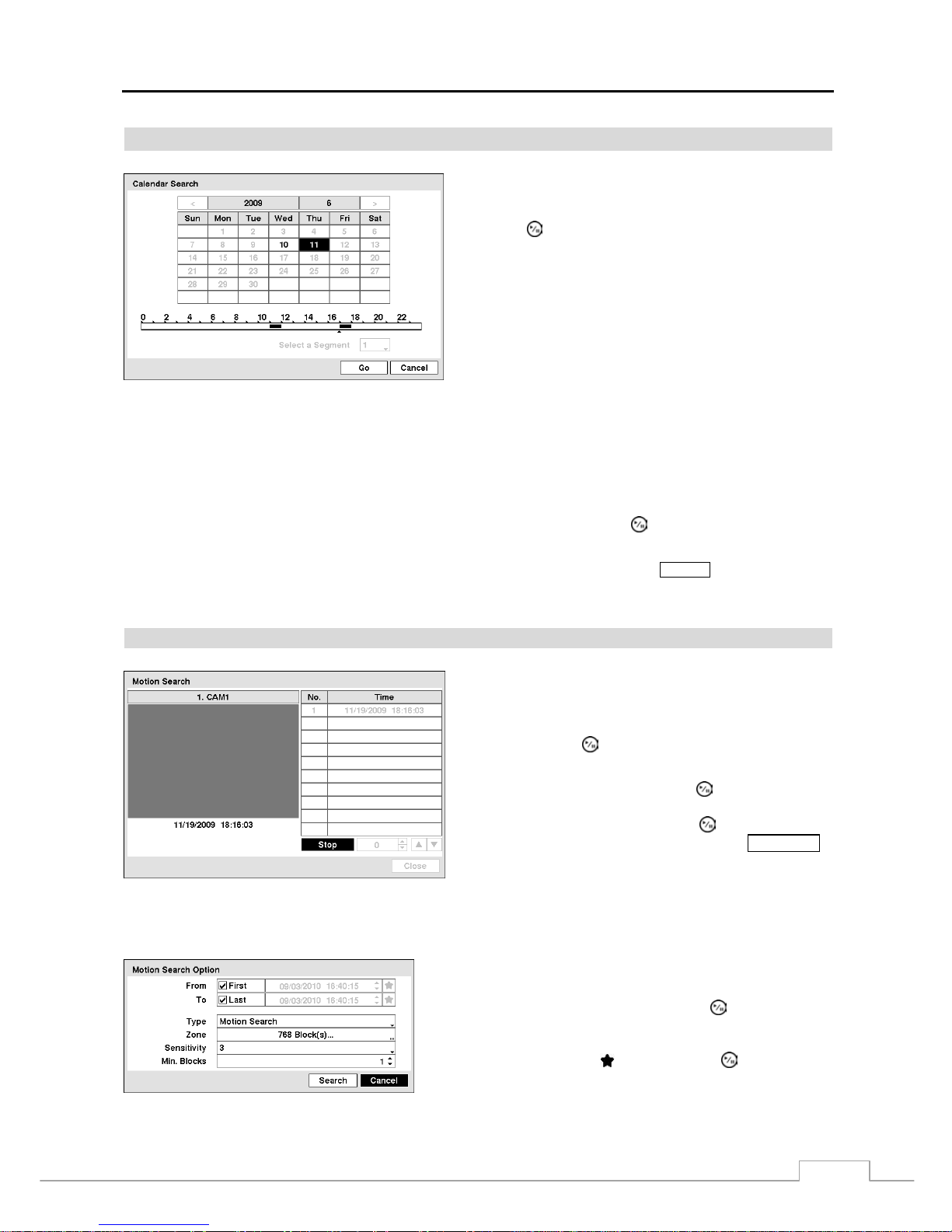
Digital Video Recorder
53
Calendar Search
Figure 67 — Calendar Search screen.
Days with recorded video display on the calendar with white
numbers. You can highlight the days with recorded video by
using the arrow buttons. Once you have highlighted a day,
press the
(Play/Pause) button to select it.
A time bar displays at the bottom of the calendar. Hours in
which video was recorded will be highlighted with blue. You
can use the Up and Down arrow buttons to highlight the time
bar. Once the time bar is highlighted, you can select the time
by using the Left and Right arrow buttons
.
NOTE: The time bar is in one-hour segments. If a segment
is highlighted, it means that some video was recorded
during that hour. However, it does NOT mean video was
recorded for the entire hour.
If the DVR’s time and date have been reset to a time that is earlier than some recorded video, it is possible for the DVR
to have more than one video stream in the same time range. Move to Select a Segment, and select the video stream you
want to search. Ref er to th e Appendix – Time Overlap for further information on searching time-overlapped video streams.
NOTE: The lower number of the Segment indicates the latest recorded video.
Once you have set the date and time you want to search, highlight Go and press the button. The selected date and
time will display.
NOTE:
It is possible that no recorded image displays on the current screen. Press the
DISPLAY button and change
the screen mode to 4x4. You will be able to easily see the camera have recorded video during target
time.
Motion Search
Figure 68 — Motion Search screen.
The Motion Search… can be selected from the Search menu
while the DVR displays the camera full screen. The Motion
Search screen displays a list of motion events. Use the arrow
buttons to highlight the event for which you would like to see
video and press the
(Play/Pause) button to display the video
associated with the selected event on the small search screen.
Highlighting Close and pressing the button will extract
the video associated with the Motion event and display the
first image of the event. Pressing the
button will start
playing the “event” video segment. Pressing PLAYBACK
returns to live monitoring
.
You can also narrow your event search by selecting the Option… button and setting up the new search condition.
You can search video from the first to last recorded images, or you
can set the start and stop times and dates.
Highlight the box beside From and press the
button to toggle
between On and Off. When set to Off, you can enter a specific Date
and Time. When set to On, the search will be from the first recorded
image. When highlighting
and pressing the button the
bookmark list displays and the bookmark point you selected will be
the starting date and time.
Page 62
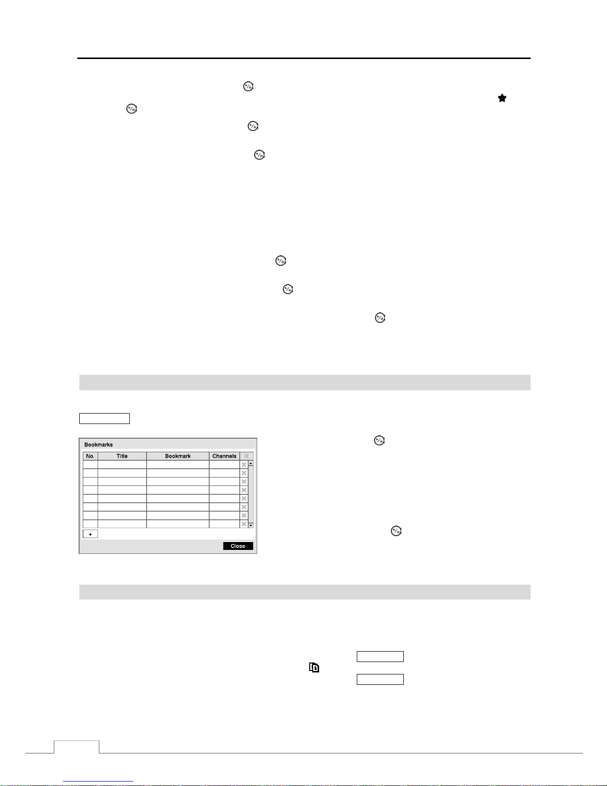
User’s Manual
54
Highlight the box beside To and press the button to toggle between On and Off. When set to Off, you can enter a
specific Date and Time. When set to On, the search will be from the last recorded image. When highlighting
and
pressing the
button the bookmark list displays and the bookmark point you selected will be the ending date and time.
Highlight the box beside Type and press the
button. You can select between Motion Search and Museu m Search.
Motion Search detects motion in the defined area. Museum Search detects if a defined object has moved.
Highlight the box beside Zone and press the
button. An image from the video appears with a gr id overl aid. You
can turn sensor blocks On and Off to define the area of the picture in which you want to search for motion.
NOTE: Defining the area of the image in which you want to search for motion is nearly identical to setting up
the DVR for Motion Detection. Please refer to Motion Detection Screen in Chapter 3 — Configuration
for more detailed instructions on setting up the detection blocks.
When setting the Museum Search Zone, the zone should be pla ced insid e of the border li ne of the target
object. If the selected block is placed on the border line, the sensitivity of the Museum Search may decrease.
The zone should be placed or focused on the centre or, at least, within the outline of targeted object.
Highlight the box beside Sensitivity and press the
button. You will be able to select from 1 (low sensitivity) to 5
(high sensitivity).
Highlight the box beside Min. Blocks and press the
button. You will be able to set the number of sensor blocks
that must be activated. Setting the Min Blocks will only be available if Motion Search is selected.
Once you set your desired search conditions, highlight Search and press the
button to display the search results in
the Motion Search screen. Selecting Cancel exits the screen without saving the changes.
When you search for motion events of another camera, you will be asked whether or not you want to delete the previous
search results from the list.
Bookmarks
The Bookmarks screen can also be accessed by selecting Bookmark in the Search – Go To menu or pressing the
BOOKMARK button on the remote control when in playback mode.
Highlight + and press the (Play/Pause) button to add the current
playback point to the bookmark list. Highlight the Title box and
enter the name of the registered bookm ark. Use the virtual k eyboard
to enter the bookmark name.
NOTE: Up to 64 bookmarks can be registered.
Use the arrow buttons to highlight the bookmark point for which
you would like to see video. The selected bookmark will display
on the screen by pressing the
button.
Figure 69 — Bookmarks screen.
Clip-Copy
Video clips can be copied on an internal DVD RW drive, or external USB hard disk or flash drive. The copied video
clips can be viewed on computers running Microsoft Windows 98, ME, 2000, XP, Vista or 7. Ref er to the Appendix
– USB Hard Disk Drive Preparation for information on preparing the external drive for clip copy.
Selecting A–B Clip-Copy in the Search – Export menu or pressing the CLIP COPY button during the playback will
set the starting point of the video to be clip copied, and the
icon displays at the bottom-left corner of the screen.
Selecting A–B Clip-Copy in the Search – Export menu or pressing the
CLIP COPY button again will set the ending
point of the video to be clip copied by displaying the Clip-Copy screen.
Page 63
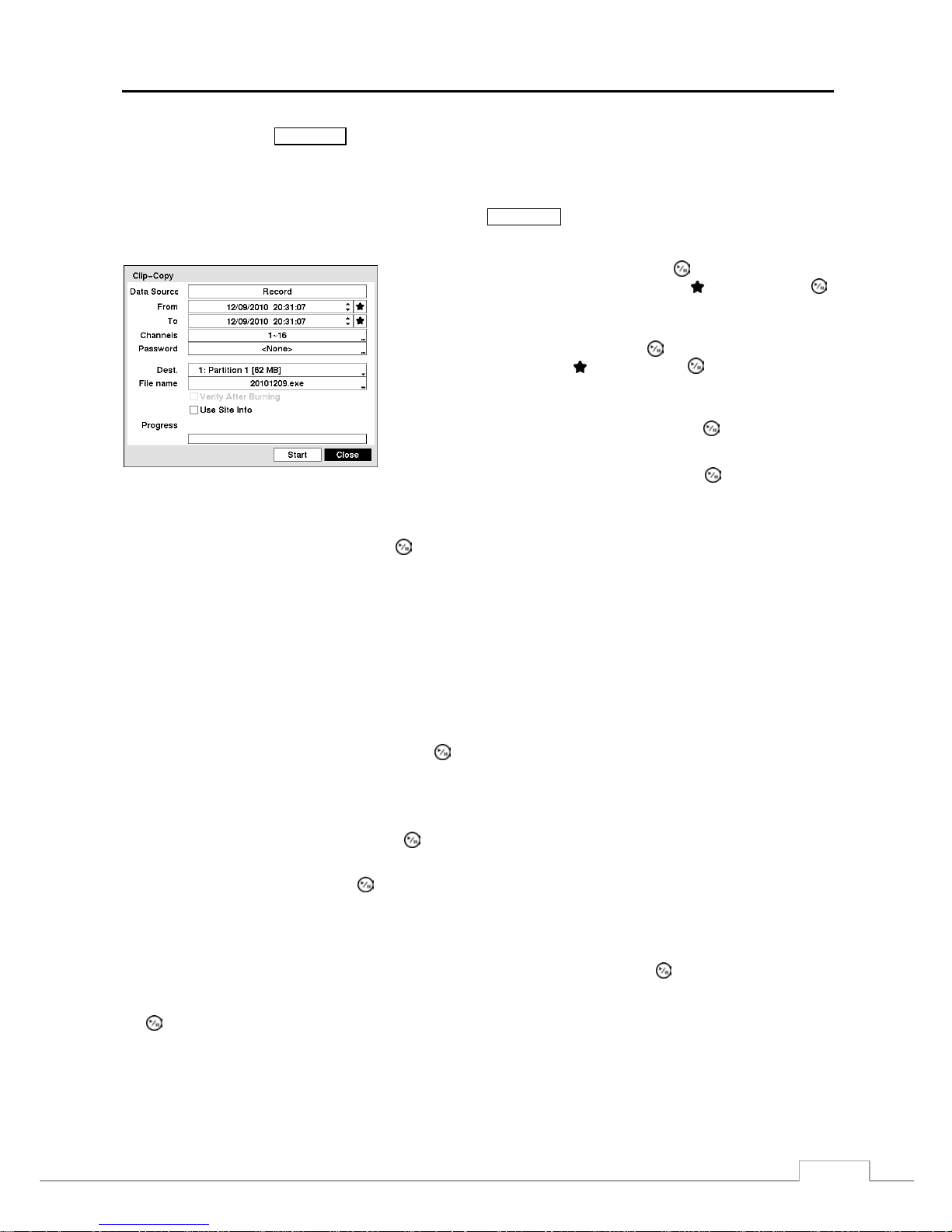
Digital Video Recorder
55
Pressing and holding the
CLIP COPY button for more than three seconds while in the Search mode or Live Monitoring
mode initiates the One-Touch Clip Copy function. The last recorded image will be the ending point of video to be
clip copied, and the system will automaticall y begin to calculate the possible video data size that th e selected storage
media can handle.
Select Clip-Copy in the Search – Export menu or press the CLIP COPY button while in the Search mode or Live
Monitoring mode, and the Clip-Copy screen appears to allow clip copy setup.
Figure 70 — Clip-Copy screen.
Highlight the box beside From and press the
(Play/Pause) button to
set a starting date and time. When highlighting
and pressing the
button the bookmark list displays and the bookmark point you selected
will be the starting date and time.
Highlight the box beside To and press the
button to set an ending date
and time. When highlighting
and pressing the button the bookmark
list displays and the bookmark point you selected will be the ending date
and time.
Highlight the box beside Channels and press the
button. You can
select the cameras that you would like to include in your video clip
.
Highlight the box beside Password and press the
button. A virtual
keyboard appears allowing you to enter the password for reviewing the
video clips
.
Highlight the box beside Dest. and press the
button. You can select the storage device on which you would like to
record the video clip. You can choose from Internal DVD RW and USB Storage.
CAUTION: The USB device for clip copy must be FAT 16 or FAT32 format.
NOTE: While copying video clips on the DVD RW, the recording speed might decrease.
While copying video clips on the DVD RW, the DVR will stop archiv ing video data until clip copy is finished.
When the error message “Firmware updat e of the optica l driv e is required ” disp lay s, update th e firm ware
of the installed DVD RW drive. Please follow the instructions described in Chapter 3 – Configuration –
System Information section.
The DVR automatically assigns a file name to the video clip. However, you can give the video clip file a different name.
Highlight the box beside File Name and press the
button. A virtual keyboard appears. Enter a file name for the
video you are backing up and select Close. The DVR will automatically add the camera number (f or example “01”)
and “.exe” to the file name.
NOTE: When naming a file, you cannot use the following characters: \, /, :, *, ?, “, <, >, |.
Highlight Verify After Burning and press the button. This will toggle between On and Off. When this featur e is
On, you can verify that the data is written on the DVD RW properly.
Highlight Use Site Info and press the button. This will toggle between On and Off. When this feature is On, you
can add the site information to the file name for the video you are backing up.
NOTE: When the site information is added to the file name, some special characters (\, /, :, *, ?, “, <, >, |) in the
site information will be converted to “_”.
Once you have given the video clip a file name, highlight the Start button and press the button. The confirmation
screen displaying data size will appear. When the storage device does not have enough space, the DVR will ask if you
want to copy as much of the video clip as possible in the available space. Highlight the Continue button and press
the
button to continue clip copy.
Once the clip copy starts, you can cancel it by selecting Cancel or hide the screen by selecting Close. When selecting
Close, Clip Copy continues and a confirmation screen will display when complete.
Page 64

User’s Manual
56
NOTE: Only 4.7GB DVD media is available. To clip copy video on DVD media using remaining space, the size
of previously recorded data on the DVD media should be less than 4GB.
Select the Full Erase option when erasing recorded data on DVD media, otherwise the media will not
operate properly when rewritten.
The file size for clip copy is limited to 30GB. When copying video clips larger than 2GB, the video clips
will be save in units of 2GB. For example, 3 individual 2GB files will be created when saving a 6GB video
clip. However, the file size for the One-Touch Clip Copy is limited to 2GB.
You can use other functions on the DVR while video is being backed up. To do th is, high light the Close button and
press the
button. You can return to the Clip-Copy screen at any time to check the progress.
You do not need to install any special software on your personal computer to review the video clips. Refer to RAS
manual for instructions on how to review video clips you have copied.
NOTE: During Clip Copy, you cannot shut the system down, clear data on the storage device, or format the
storage device.
CAUTION: Do NOT disconnect the USB cable or the power from the external drive while copying
video clips. If the external drive is shut down or the USB cable is disconnected while
copying video clips, THE DVR SYSTEM MAY NOT WORK NORMALLY OR THE EXTER NAL
DRIVE COULD BE DAMAGED, and you will get an error message the next time you try
to copy video clips. You will need to power down the DVR and restart it to get rid of the
error message. Once the file system of the USB hard disk drive has been corrupted, this
error message cannot be dismissed. Even after restarting the DVR it may automatically
restart while preparing to clip copy. You must recover the file system us ing the recovery
program, or you must reformat the hard disk drive.
Page 65

Digital Video Recorder
57
Appendix
USB Hard Disk Drive Preparation
Preparing the USB hard disk drive in Windows 2000
NOTE: Preparing a USB hard disk drive under Windows XP and Window Vista is almost identical to Windows 2000.
1. Connect the USB hard disk drive to your computer using the USB Cable.
2. Turn on your computer.
3. The USB device icon should display on the Taskbar.
4. If the USB hard disk drive is partitioned or has data, it will show up in My Computer as a hard disk drive
icon. Check the file system by right clicking on the icon and checking under Properties > General > File
System. If the file system is NOT FAT32 format, format the USB hard disk drive using the FAT32 format.
5. If the USB hard disk drive is not partitioned, go to Administrative Tools in Control Panel and launch Computer
Management. Open Disk Management in Storage and right click an unallocated region of the USB hard
disk drive. Then, click Create Partition.
6. In the Create Partition wizard, click Next then Primary Partition , and follow the ins tructions on the screen.
Make sure that the FAT32 is selected for the file system.
NOTE: The partition size should be less than 32GB because of Microsoft limitations.
After formatting is complete, the USB hard disk drive will be added to My Computer.
7. Connect the USB hard disk drive to the DVR.
Preparing the USB hard disk drive in Windows 98
NOTE: Preparing a USB hard disk drive under Windows ME is almost identical to Windows 98.
1. Connect the USB hard disk drive to your computer using the USB Cable.
2. Turn on your computer. The Add New Hardware wizard window will appear.
3. Install the device driver for the USB backup device following the instructions provided with your USB hard
disk drive.
4. If the USB hard disk drive is partitioned or contains data, it will show up in My Computer as a hard disk
drive icon. Check the file system in Properties > General > File System. If the file system is NOT FAT32
format, format the USB hard disk drive with FAT32 format.
5. Run the FDISK utility by clicking Start then RUN. Type “fdisk” and click OK.
6. When the MS-DOS command prompt appears, type “Y” and hit the enter key.
7. In the FDISK Option menu, choose “5. Change current fixed disk drive.”
8. Choose the appropriate letter corresponding to the USB hard disk drive.
9. In the FDISK Option menu, choose “1. Create DOS partition or Logical DOS Drive.”
10. In the Create DOS Partition or Logical DOS Drive menu, choose “1. Create Primary DOS Partition.” And
Type “Y” to use all available spac e and hit the enter key. Hit ESC to exit the screen after the USB hard disk
drive partition is created.
11. Restart your computer and verify the newly created drive is in My Computer.
12. Right click the newly created hard disk drive icon and select “Format”.
13. In the Format Screen, select “Full” as the “Format type” and click “Start”.
14. After formatting is complete, connect the USB hard disk drive to the DVR.
WebGuard
WebGuard allows you to access a remote DVR, monitor live video images and search recorded video using Internet
Explorer web browser anytime from virtually anywhere.
Page 66
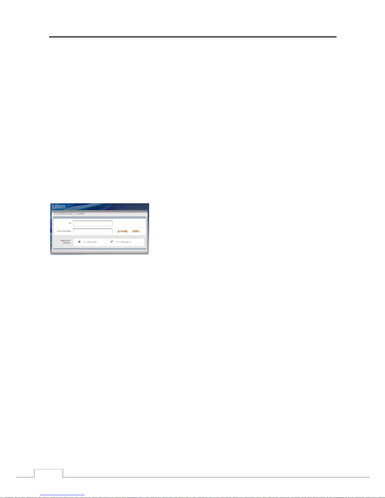
User’s Manual
58
Computer system requirements for using the WebGuard program are:
Operating System: Microsoft
®
Windows® XP x86 (32 Bit) (Service Pack 3), Microsoft® Windows® Vista x86 (32 Bit)
(Service Pack 1), Microsoft
®
Windows® 7 x86 (32 Bit)
CPU: Intel Pentium III (Celeron) 600MHz or faster
RAM: 128MB or higher
VGA: 8MB or higher (1024x768, 24bpp or higher)
Internet Explorer: Version 6.0 or later
Start Internet Explorer on your local PC. You can run the WebGuard program by entering the following informatio n
in the address field.
– “http://IP address:port number” (The DVR IP address and the WebGuard port number (default: 12088) set in the
Network setup screen (WebGuard tab))
– Or, “http://DVRNS server address/DVR name” (The DVRNS server address and the DVR name registered on the
DVRNS server)
– Or, “http://www.dvronline.net” (Entering the DVR IP address or the DVR name will be required w hen logging in)
NOTE: You will need to get the appropriate IP address for the DVR you want to connect to and the WebGuard
port number from your network administrator.
WebGuard only works with Microsoft Internet Explorer and will NOT work with other browsers.
NOTE: Do NOT close the LOGIN window during the WebGuard operation, otherwise, it will cause a script error
when switching between Web monitoring and Web search modes and running the WebGuard program
again will be required.
When running the updated WebGuard for the first time, In ternet Explorer might occasionally load the
information of the previous version. In this case , d elete the tempora ry inte rnet f iles by sel ecting Too ls
Internet Options General tab, and then run WebG uard again.
There might be a problem that the bottom of WebGuard page is cropped due to the address or status
bars in Microsoft Internet Explorer 7.0. In this situ ation , it is recommend ed that websi tes open wind ows
without address or status bars by changing the inte rnet s etting . (Go to the Tools Internet Options
Security tab Click the Custom level… button Select Enable for the Allow we bsites to op en windows
without address or status bars option)
When running WebGuard in the Microsoft Windows Vista operati ng sy stem, it is recom mended to start
Internet Explorer with el evated administrator permis si ons . Cl ic k the right mouse button on th e In te r net
Explorer icon and select the Run as administrator option from the context menu. Otherwise, some
functions of the WebGuard might be limited to use.
There might be a problem with screen display or screen update due to low image transmission speed
when using the Microsoft Windows Vista operating system. In this situation, it is recommended that
you disable the Auto Tuning capability of your computer.
Run the Command Prompt with elevated administrator permissions (Go to the Start Menu
Accessories Command Prompt Click the right mouse button and select the Run as administrator
option). Then enter “netsh int tcp set global autot uninglev el=disable ” and hit the enter key . Resta rt
your computer to apply the changes.
If you want to enable the Auto Tuning capability again, enter “netsh int tcp set global autotuninglevel=
normal” after running the Command Prompt with elevated administrator permissions. Restart your
computer to apply the changes.
Select between the WEBWATCH (Web monitoring) and WEBSEARCH
(Web search) modes. Entering ID and PASSWORD and clicking the
[LOGIN] button logs in using the selected mode.
You will need to enter the DVR IP address in the DVR ADDRESS field
when running the WebGuard program by entering http://ww w.dvronline.net.
Selecting the Use DVRNS option allows you to enter the DVR name
registered on the DVRNS server instead of the IP address. You must enter
the DVRNS server address and port number in the SETUP setting when
selecting the Use DVRNS option.
Page 67
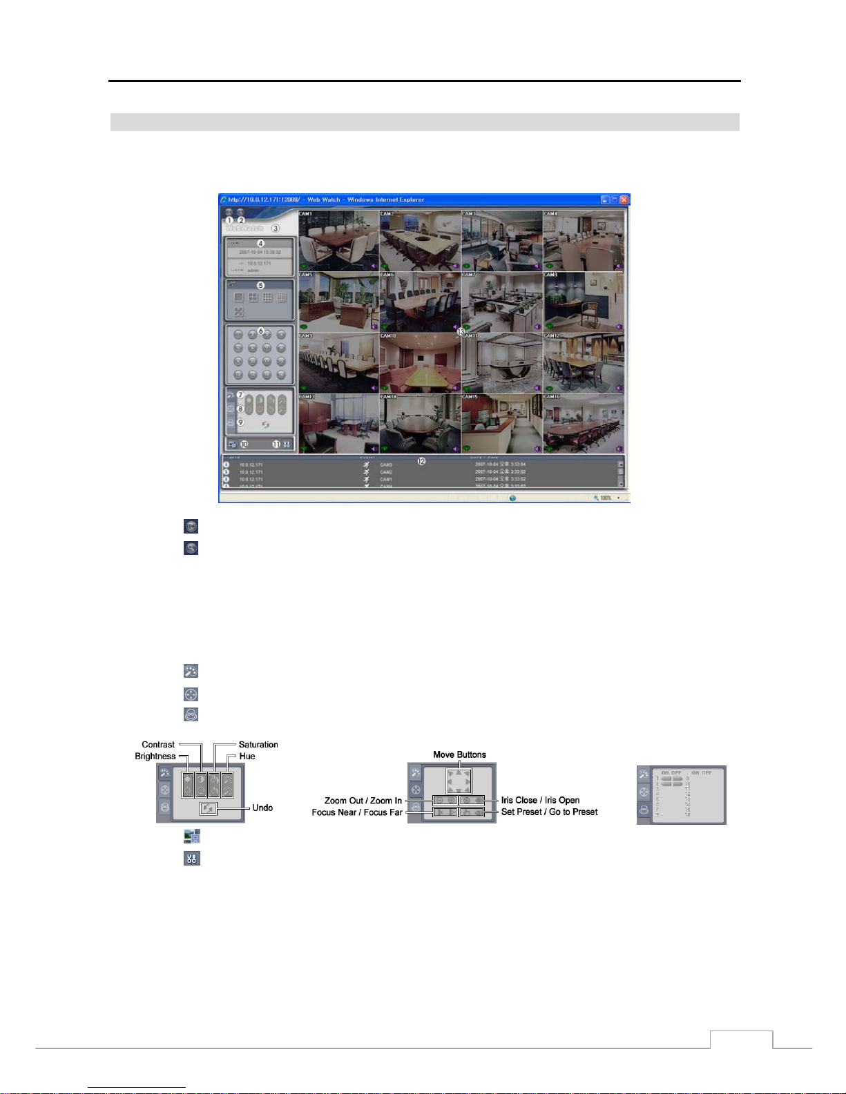
Digital Video Recorder
59
Web Monitoring Mode
WebWatch is a remote web monitoring program that allows you to monitor live video transmitted in real-time from
the remote DVR.
① Click the
to log out the WebGuard program.
② Click the to access to the web search mode.
③ Position the mouse pointer on the WebWatch logo to see the version of the WebGuard program.
④ The DVR information window displays the login information of WebGuard.
⑤ Click the screen format to select the desired display mode. When changing the screen format, the selected camera
on the current screen will be located in the first cell of the new layout.
⑥ Click the camera button to select the camera to be viewed.
⑦ Click the to adjust the brightness, contrast, saturation and hue of monitoring image.
⑧ Click the
to control pan, tilt and zoom of the camera from a remote site.
⑨ Click the to control alarm out devices at the remote site.
⑩ Click the to save the current image as a bitmap or JPEG file format.
⑪ Click the to set up the image drawing mode and OSD display. You can adjust the display speed by changing
the image drawing mode, and select OSD information to be displayed on the screen.
⑫ The event status window at the bottom displays a list of events that were detected from the remote site.
⑬ Selecting a camera on the screen and clicking the right mouse button displays the text menu screen.
Page 68
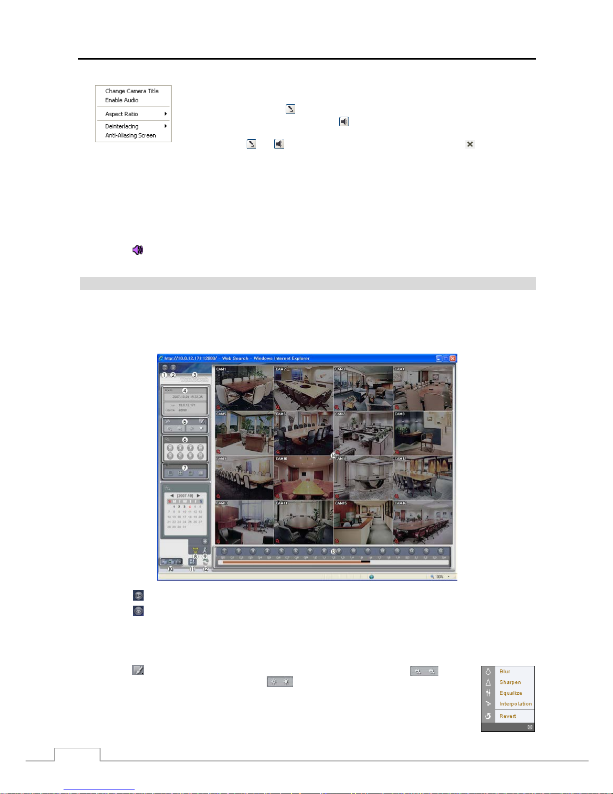
User’s Manual
60
Change Camera Title: Changes the camera name.
Enable Audio: Enables audio communication with the remote site. When the audio control
panel displays, click the
to send audio to the connected remote site and click the button
again to stop sending audio. Click the
to monitor live audio from the connected remote
site through the attached speaker and click the button again stop monitoring live audio.
Clicking both
and allows two-way communication. Clicking the disables audio
communication.
Aspect Ratio: Changes the image aspect ratio.
Deinterlacing: Using a deinterlace filter for interlaced video enhances image display quality
by eliminating horizontal scan lines and noise in areas with motion.
Anti-Aliasing Screen: Enhances image display quality by eliminating stair stepping
(aliasing) effects in the enlarged image.
NOTE: A camera name change in the Web Watch mode does not affect the camera name set up on the remote
site. Leaving the Camera Title blank causes the camera name set up on the remote site to display.
The
icon will display on each camera screen when audio communication is available between the
WebGuard system and a DVR.
Web Search Mode
WebSearch is a remote web search program that allows you to search recorded video on the remote DVR.
NOTE: The remote site connection in the Web Search mode will automatically be disconnected if there is no
activity for 30 minutes.
① Click the to log out the WebGuard program.
② Click the to access to the web monitoring mode.
③ Position the mouse pointer on the WebSearch logo to see the version of the WebGuard program.
④ The DVR information window displays the time information of recorded data on the remote DVR and login
information of WebGuard.
⑤ Click the to blur, sharpen, equalize and interpolate playback images. Click the to zoom
out or zoom in the recorded image. Click the
to adjust the brightness of the recorded images.
NOTE: Image processing works only in the pause mode.
⑥ The playback function buttons include fast backward, pause, play, fast forward, go to the first image,
go to the previous image, go to the next image, and got to the last image.
Page 69
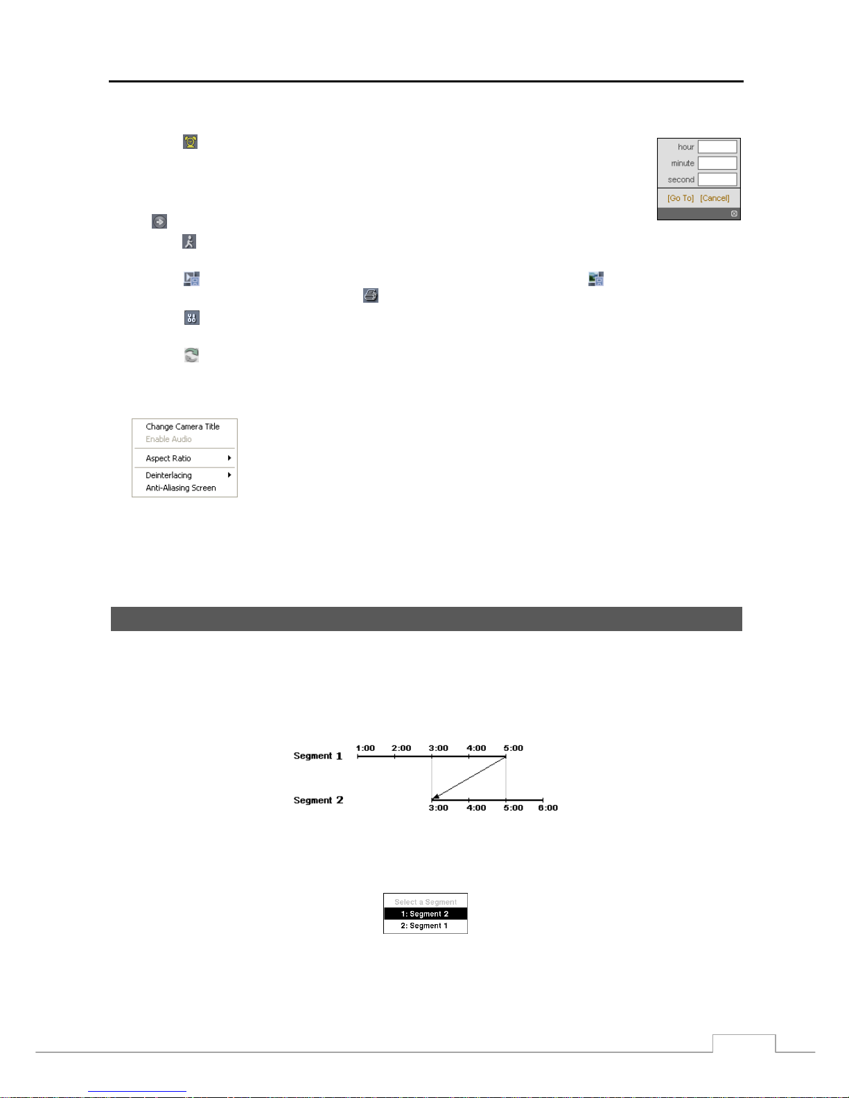
Digital Video Recorder
61
⑦ Click the screen format to select the desired display mode.
⑧ Click the to enter the time-lapse search mode which allows you to search for recorded data by
time and then play back images found within the time parameters. The Timetable window located
at the bottom displays the time information for the image of the date selected on the calendar.
If more than one video stream in the same time range, you can select the video stream you want
to search. Clicking a specific time displays the image recorded at that time on the screen. Selecting
the
allows you to display an image from a specific time.
⑨ Click the to enter the event search mode which allows you to search for event log entries using specific conditions
and play back the images associated with those event entries.
⑩ Click the to save any video clip of recorded data as an executable file, or click the to save the current image
in a bitmap or JPEG file format. Click the to print the current image on a printer connected to your computer.
⑪ Click the to set up the image drawing mode and OSD display. You can adjust the display speed b y changing
the image drawing mode, and select OSD information to be displayed on the screen.
⑫ Click the to reload the recording data.
⑬ The Timetable displays recorded data of the selected camera by time (in hour segments).
⑭ Selecting a camera on the screen and clicking the right mouse button displays the text menu screen.
Change Camera Title: Changes the camera name.
Enable Audio: Plays audio while playing back recorded video that has recorded audio.
(Single-Screen Layout Only)
Aspect Ratio: Changes the image aspect ratio.
Deinterlacing: Using a deinterlace filter for interlaced video enhances image display
quality by eliminating horizontal scan lines and noise in areas with motion.
Anti-Aliasing Screen: Enhances image display quality by eliminating stair stepping
(aliasing) effects in the enlarged image.
NOTE: A camera name change i n the Web Search mode does not aff ect the camera name set up on the remote
site. Leaving the Camera Title blank causes the camera name set up on the remote site to display.
Time Overlap
If the DVR’s time and date have been reset to a time that is earlier than the existing recorded video, it is possible for
the DVR to have more than one video stream in the same time range. In this case, you can search ov erlapping video
streams individually by selecting a specific segment. For example, when the DVR has recorded video from one to
five o’clock and the user changes the time backward from five to th ree o’clock and t hen continues recording until s ix
o’clock, there will be two video streams and segments from three to five o’clock.
You can search overlapping video streams by selecting a specific time or time range. If you want to search recorded
video at four o’clock during the overlapping time range using a se arch menu such as Go to the Date/Time, select the
segment you want to search.
If you want to search recorded video from four to five o’clock during the overlapping time range us ing a search menu
such as Event Log Search or Motion Sear ch, it is possible for the DVR to have two overlapping start and stop times.
You will be asked to select one of the overlapping start and stop times from the search time ranges as follows:
Page 70
User’s Manual
62
From four o’clock of the first segment to five o’clock of the first segment
From four o’clock of the first segment to five o’clock of the second segment
From four o’clock of the second segment to five o’clock of the second segment
Map of Screens
Page 71
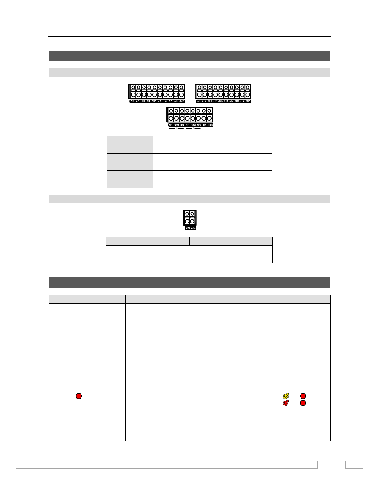
Digital Video Recorder
63
Connector Pin Outs
I/O Connector Pin Outs
AI (1 to 16)
Alarm Inputs 1 to 16
GND
Chassis Ground (6 connectors)
NC
Relay Alarm Output (Normally Closed)
COM
Relay Common
NO
Relay Alarm Output (Normally Open)
ARI
Alarm Reset In
RS485 Connector Pin Outs
Master Unit Slave Unit
+
To TX+/ RX+
− To
TX-/ RX-
Troubleshooting
Problem Possible Solution
No Power
Check power cord connections.
Confirm that there is power at the outlet.
No Live Video
Check camera video cable and connections.
Check monitor video cable and connections.
Confirm that the camera has power.
Check camera lens settings.
Live Video Very Bright
If a cable is attached to the “Loop” connector, make certain it is connected to a
properly terminated device.
DVR has stopped recording
If hard disk drive is full, you will either need to delete video or set the DVR to th e
Overwrite Mode.
The icon displays,
however, the DVR is not
recording.
When the DVR is in the Pre-Event recording mode, the yellow
and display
when there is no event, and the DVR is not recording. The red
and display
when any event occurs and the DVR starts recording.
While upgrading the system,
the DVR keeps rebooting and
the upgrade fails.
If the current system version is higher than the upgrade package file version, you
should reset the DVR first using the Factory Reset. When using the Factory Reset,
you will lose any settings you have saved.
Page 72
User’s Manual
64
System Log Notices
Boot Up Remote Setup Fail Disk ‘No.’ : Removed
Shutdown Setup Imported Auto Deletion
Restart Setup Import Failure Search Begin
Upgrade Setup Exported Search End
Upgrade Fail Setup Export Failure Clip-Copy Begin
Power Failure Setup Export Cancel Clip-Copy End
Time Change Schedule On Clip-Copy Cancel
Time Zone Change Schedule Off Clip-Copy Fail
Time Sync Panic On Clip-Copy User:
Time Sync Fail Panic Off Clip-Copy From:
Disk Bad Clear All Data Clip-Copy To:
Login Clear Disk Clip-Copy Duration of Video:
Logout Format Disk Clip-Copy Camera:
Setup Begin Disk Full Callback Fail
Setup End Disk Config Change
Remote Setup Change Disk ‘No.’ : ‘serial number’
Error Code Notices
System Upgrade Related Clip Copy Related
No. Description No. Description
0
Unknown error.
0
Unknown error.
1
File version error.
1
Device error.
2
Operating system version error.
2
Mounting failed.
3
Software version error.
3
No media.
4
Kernel version error.
4
Invalid media.
100
Upgrade device mounting failed.
5
File already existed.
101
Package is not found.
6
Not enough space.
102
Extracting package failed.
7
Creating temporary file failed.
103
LILO failed.
8
Opening disk failed.
104
Rebooting failed.
9
Formatting disk failed.
105
Invalid package.
10
Database has been changed.
106
ODD firmware upgrade failed.
11
Appending failed.
300
Remote connection failed.
12
Bad sector.
301
Remote network error.
13
No executable file.
302
Remote upgrade is not authorized.
14
Opening executable file failed.
303
Saving remote package failed.
15
Writing executable file failed.
304
Remote upgrade is cancelled by the user.
16
Creating image failed.
400
USB device mounting failed.
17
Burning failed.
401
Reading upgrade package on the USB device failed.
18
Burning is out of time.
402
Copying upgrade package on the USB device failed.
19
Connecting device failed.
403
USB device is not connected.
20
Device is busy.
404
USB device is being used.
21
Unsupported file system.
405
Unsupported file system.
22
Verify failed.
500
System is busy clip copying.
Page 73
Digital Video Recorder
65
Specifications
VIDEO
Signal Format NTSC or PAL (Auto Detect)
Video Input Composite: 8 or 16 looping inputs, 1 Vp-p, auto-terminating, 75 Ohms
Monitor Outputs
Composite: 1 BNC, 1 Vp-p, 75 Ohms
SPOT: 1 BNC, 1 Vp-p, 75 Ohms
VGA: 1
Video Resolution
Composite: 720x480 (NTSC), 720x576 (PAL)
VGA: 800x600, 1024x768, 1280x1024 @ 60Hz
Record Speed
(images per second)
Real-time: 480ips (NTSC), 400ips (PAL) @ CIF (16-ch Model)
Real-time: 240ips (NTSC), 200ips (PAL) @ CIF (8-ch Model)
Playback Speed
(images per second)
Full Duplex: 480ips (NTSC), 400ips (PAL) @ CIF (16-ch Model)
Full Duplex: 240ips (NTSC), 200ips (PAL) @ CIF (8-ch Model)
INPUTS/OUTPUTS
Alarm Input
8 or 16 terminal, programmable as NC or NO, 2.4V (NC) or 0.3V (NO) threshold,
5VDC
Alarm Output 2 relay output, programmable as NC or NO, 2A@125VAC, 1A@30VDC
Alarm Reset Input 1 TTL, terminal block
Internal Buzzer 80dB at 10cm
Network Connectivity 10/100 Mbps Ethernet (RJ-45)
Audio Input RCA Input: 4 Line In
Audio Output RCA Output: 1, Line Out
CONNECTORS
Video Input Composite: 8 or 16 BNC
Video Loop Composite: 8 or 16 BNC (Auto Terminating)
Monitor Output
Composite: 1 BNC
VGA: 1 VGA
SPOT (Composite): 1 BNC
Audio In 4 RCA connector
Audio Out 1 RCA connector
Alarm Input/Output Terminal Blocks
Ethernet Port RJ-45
RS232C Serial Port DB9 (P)
RS485 Serial Port Two-connector terminal block
IR Port 1 Remote Control
USB Port 2 (USB 2.0)
STORAGE
Primary Storage SATA hard disk drive (up to 3) (up to 2 with an internal DVD RW drive)
Secondary Storage*
Built-in DVD RW drive
USB hard disk drive or flash drive
* When installing an internal DVD RW drive, connect the SATA I/O cable to the SATA3 socket.
Page 74
User’s Manual
V1.2
66
GENERAL
Dimensions (W x H x D) 16.9" x 3.5" x 15.9" (430mm x 88mm x 405mm)
Unit Weight 16.8 lbs. (7.6kg)
Shipping Weight 26.3 lbs. (11.9kg)
Shipping Dimensions
(W x H x D)
21.3" x 11.4" x 23.2" (540mm x 290mm x 590mm)
Operating Temperature 41°F to 104°F (5°C to 40°C)
Operating Humidity 0% to 90%
Power 100 to 240 VAC, 1.2 – 0.6 A, 60/50Hz
Power Consumption Max. 45W
Approvals FCC, UL**, CB, CE
** CAUTION: Risk of Explosi on if Battery is replaced by an Inco rrect Ty pe. D ispose of U sed Batteries Acco rding t o the Instructi ons. T his equ ipm ent
is indoor use and all the communication wiring are limited to inside of the building.
Specifications are subject to change without notice.
 Loading...