

Matrix Fitness S7XE - 03 Service Manual

S 7 X E - 0 3 S T E P P E R
S E R V I C E M A N U A L

TABLE OF CONTENTS
CHAPTER 1: SERIAL NUMBER LOCATION ................................................................... 1
CHAPTER 2: IMPORTANT SAFETY INSTRUCTIONS
2.1 Before Getting Started .............................................................................................. 3
2.2 Read and Save These Instructions ........................................................................... 3
2.3 Electrical Requirements ............................................................................................. 4
CHAPTER 3: PREVENTATIVE MAINTENANCE
3.1 Recommended Cleaning Tips ................................................................................... 5
3.2 Check for Damaged Parts ......................................................................................... 5
3.3 Care and Maintenance Instructions .......................................................................... 6
3.4 Touch Screen Care & Cleaning.................................................................................. 7
CHAPTER 4: CONSOLE OVERLAY AND WORKOUT DESCRIPTION
4.1 Console Description .................................................................................................. 8
4.2 Workout Setup Steps - Manual .................................................................................. 9
4.3 Workout Setup Steps - Level Based .......................................................................... 9
4.4 Workout Setup Steps - Fitness Test ........................................................................... 10
4.5 Workout Setup Steps - Target Heart Rate ................................................................. 11
4.6 Workout Setup Steps - Constant Watts ..................................................................... 11
CHAPTER 5: MANAGER MODE
5.1 Manager Mode .......................................................................................................... 12
5.2 Manager Mode - About Tab ........................................................................................ 13
5.3 Manager Mode - Time Tab ......................................................................................... 14
5.4 Manager Mode - Stepper Tab .................................................................................... 14
5.5 Manager Mode - Defaults Tab .................................................................................... 15
5.6 Manager Mode - TV Tab ............................................................................................ 15
5.7 Manager Mode - Language Tab ................................................................................. 16
5.8 Manager Mode - Other Tab ........................................................................................ 17
CHAPTER 6: ENGINEERING MODE
6.1 Engineering Mode Overview ...................................................................................... 18
6.2 Engineering Mode - Calibration Tab ........................................................................... 18
6.3 Engineering Mode - Statistics Tab ............................................................................. 19
6.4 Engineering Mode - Errors Tab .................................................................................. 19
6.5 Engineering Mode - Clubs Tab ................................................................................... 20
6.6 Engineering Mode - Club ID Tab ................................................................................ 20
CHAPTER 7: SERVICE MODE
7.1 Service Mode Overview ............................................................................................. 21
7.2 Service Mode - Setup Tab .......................................................................................... 21
7.3 Service Mode - Test Tab ............................................................................................ 22
7.4 Service Mode - Log Tab ............................................................................................. 23
7.5 Service Mode - Date & Time Tab ............................................................................... 23
CHAPTER 8: TROUBLESHOOTING
8.1 Electrical Diagram ..................................................................................................... 24
8.2 Error Codes on the Console ..................................................................................... 25
8.3 LCB LED Indicators.................................................................................................... 26
8.4 Troubleshooting - Display Issues ............................................................................... 27
8.5 Troubleshooting - Error 0x04A0 ................................................................................. 28
8.6 Troubleshooting - Touch Pad Issues .......................................................................... 29
8.7 Troubleshooting - Heart Rate Issues ......................................................................... 30
8.8 TV Troubleshooting Overview .................................................................................... 31
8.9 TV Troubleshooting - Picture Fuzzy or Unclear ......................................................... 32
8.10 TV Troubleshooting - TV Will not Turn On ................................................................. 33
8.11 TV Troubleshooting - Entertainment Keypad Issues ................................................. 34

TABLE OF CONTENTS
CHAPTER 9: PART REPLACEMENT GUIDE
9.1 Console Replacement ................................................................................................ 35
9.2 Heart Rate Handlebar Replacement ......................................................................... 36
9.3 Heart Rate Grip Replacement ................................................................................... 37
9.4 Cup Holder Replacement ........................................................................................... 38
9.5 Console Keypad / Overlay Replacement ................................................................... 39
9.6 Console Mast Removal .............................................................................................. 41
9.7 Upper Stationary Handlebar Replacement ................................................................ 42
9.8 Lower Stationary Handlebar Replacement ................................................................ 43
9.9 Rear Stabilizer Cover Replacement ........................................................................... 44
9.10 Rear Stabilizer Replacement .................................................................................... 45
9.11 Shrouds Replacement ................................................................................................ 46
9.12 Lower Control Board Replacement ............................................................................ 47
9.13 Generator Belt Replacement...................................................................................... 48
9.14 Generator Replacement ............................................................................................. 49
9.15 Center Axle Set Replacement .................................................................................... 50
9.16 Drive Belt Replacement ............................................................................................ 51
9.17 Drive Axle Set Replacement ...................................................................................... 53
9.18 Pedal Replacement .................................................................................................... 55
9.19 Pedal Belt Replacement ................................................................................................. 56
9.20 Pedal Arm Replacement ................................................................................................. 57
9.21 Battery Replacement ...................................................................................................... 58
9.22 Testing the Stepper ......................................................................................................... 59
CHAPTER 10: STEPPER SPECIFICATIONS AND ASSEMBLY GUIDE
10.1 S7xe-03 Stepper Specifications ................................................................................. 60
10.2 Fasteners and Assembly Tools .................................................................................. 61
10.3 Assembly Instructions ............................................................................................... 62
10.4 Leveling the Stepper .................................................................................................. 66
10.5 TV Programming Instructions..................................................................................... 67
CHAPTER 11: SOFTWARE UPGRADE GUIDE
11.1 Software Upgrade Instructions ................................................................................... 70
III
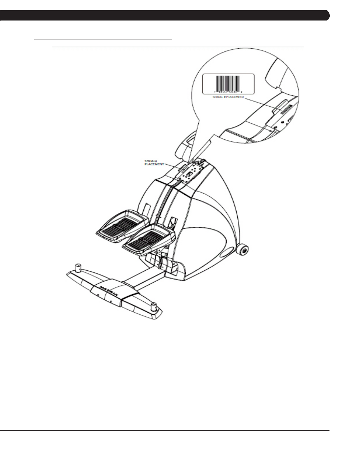
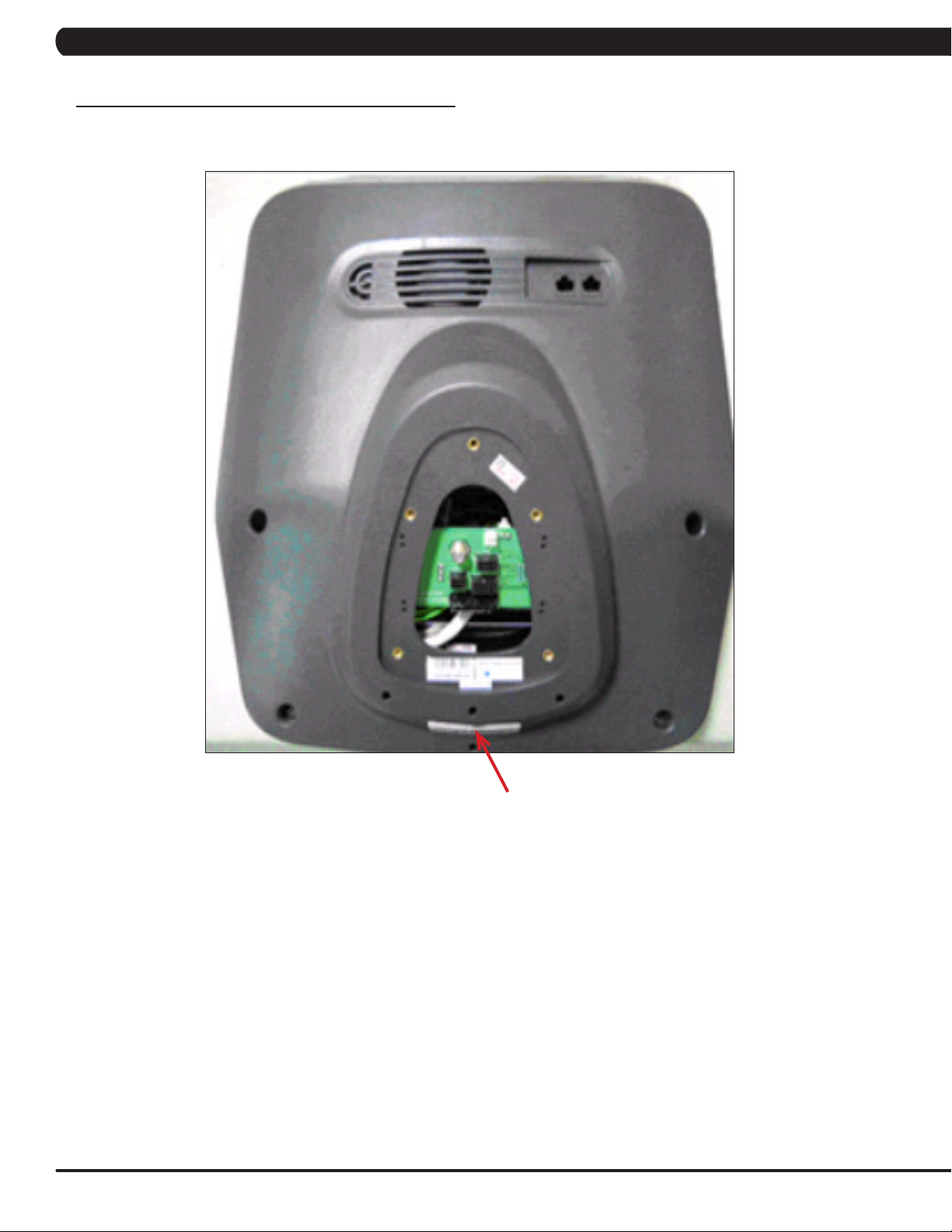
1.1 SERIAL NUMBER LOCATION
CHAPTER 1: SERIAL NUMBER LOCATION
A serial number plate is located below the bottom of the console mast beneath a rubber boot. There is also a serial number tag on the middle
of the main frame pointed towards the floor.
1
CHAPTER 1: SERIAL NUMBER LOCATION
1.1 SERIAL NUMBER LOCATION - CONTINUED
UNIVERSAL CONSOLE SERIAL NUMBER LOCATION
CONSOLE SERIAL NUMBER LOCATION
2
CHAPTER 2: IMPORTANT SAFETY INSTRUCTIONS
2.1 BEFORE GETTING STARTED
The Matrix S7xe-03 Stepper is intended for commercial use. To
ensure your safety and protect the equipment, read all instructions
before operating the stepper.
CHOOSING A SITE
The site should be well lit and well ventilated. Locate the Matrix
S7xe-03 Stepper on a structurally solid and flat surface. The
Stepper should have a clearance of 24" on the back side from the
wall or other equipment. This zone is to allow easy access to the
Stepper and gives the user an easy exit path from the machine.
If the site has a heavy plush carpet, to protect the carpeting and
machinery, you should place a rigid plastic base under the unit.
Please do not place the Matrix S7xe-03 Stepper in an area of high
humidity, such as the vicinity of a steam room, indoor pool, or sauna.
Exposure to intensive water vapor or chlorine could adversely affect
the electronics, as well as other parts of the machine.
2.2 READ AND SAVE THESE INSTRUCTIONS
To ensure your safety and protect the equipment, read all
instructions before operating the Matrix S7xe-03 Stepper.
To ensure proper use of the Stepper, make sure that all users
read this manual. Remind the users that before undertaking any
fitness program, they should obtain complete physical examinations
from their physicians. If, at any time while exercising, the user
experiences dizziness, pain, or shortness of breath, nausea or feels
faint, he or she must stop immediately.
* This stepper is only to be used for its intended purpose described in
this manual. Do not use attachments that have not been recommended
by Matrix.
* Never drop or insert objects into any opening. Keep hands away
from moving parts. If the item cannot be reached, contact a Matrix
authorized dealer for assistance.
* Never operate the unit if it is damaged, not working properly, when it
has been dropped, or has been dropped in water.
* Keep hands and feet clear at all times from moving parts to avoid
injury.
* Do not use this product outdoors, near swimming pools or in areas
of high humidity.
* Do not operate where aerosol (spray) products are being used or
when oxygen is being administered.
* Do not use this product in bare feet. Do not wear shoes with heels,
leather soles, cleats, or spikes while exercising.
* Do not remove the side covers. Service should only be done by an
authorized service technician.
* Close supervision is necessary when used near children, invalids, or
disabled people.
* When the stepper is in use, young children and pets should be kept
at least 3 meters / 10 feet away.
* Assemble and operate the stepper on a solid, level surface.
* Never face backward while using the stepper.
* Use the stationary handlebars when mounting or dismounting the
stepper.
* Do not wear clothing that might catch on any moving parts of this
stepper.
CAUTION! If you experience chest pains, nausea, dizziness,
or shortness of breath, stop exercising immediately and consult your physician before continuing.
CAUTION! Any changes or modifications to this equipment
could void the product warranty.
3
CHAPTER 2: IMPORTANT SAFETY INSTRUCTIONS
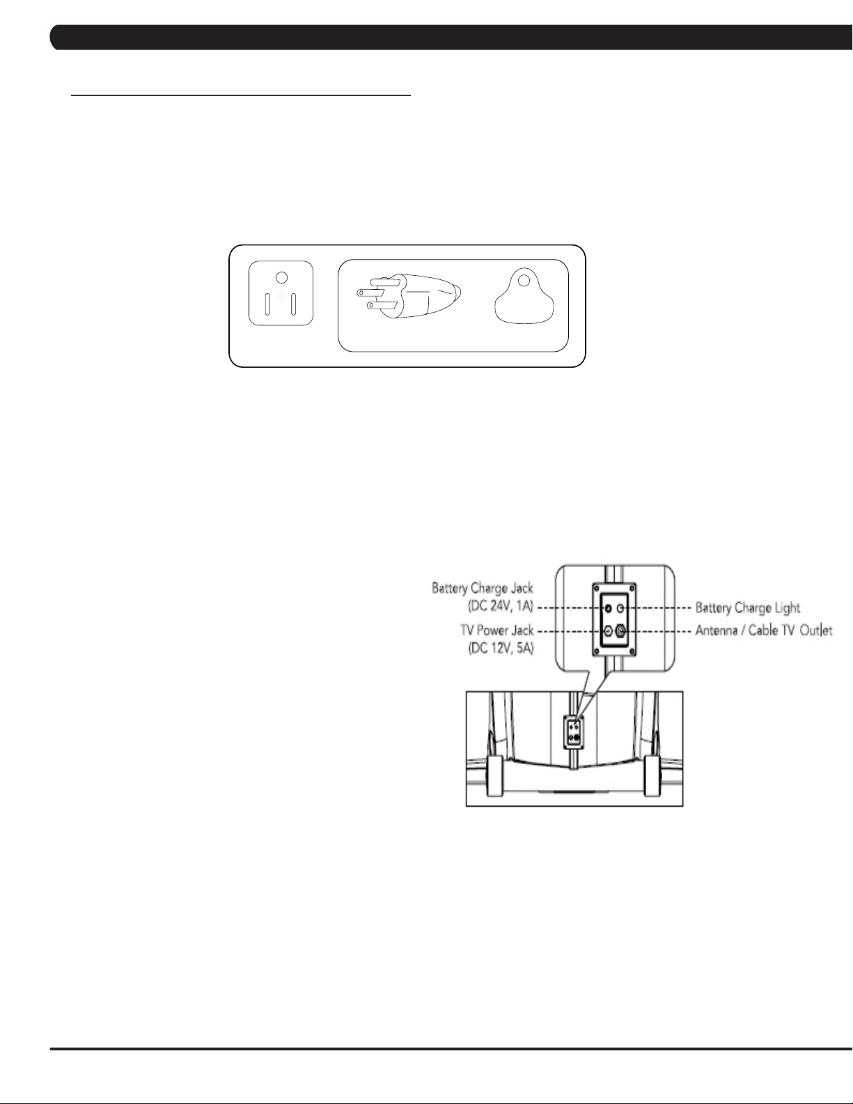
2.3 ELECTRICAL REQUIREMENTS
ELECTRICAL REQUIREMENTS
The Matrix S7xe-03 Stepper must be AC powered. This will power the console at all times and requires no minimum RPM for operation. A
powered product lowers the starting resistance and is easier to use for beginners. These units can be daisy chained together, up to 3 units per
dedicated 15 amp circuit, using a Matrix daisy chain cord adapter (sold separately).
For your safety and the performance of your Matrix product, the ground on your circuits must be non-looped. Please refer to NEC article 210-21
and 210-23. Any alterations to the standard Matrix power cords will void all warranties. If plugged in, your stepper is provided with a power cord
with a plug listed below and requires the listed outlet.
The S7xe-03 Stepper saves its battery charge by moving into a shutdown mode whenever STEP FASTER appears on the display. If the user
does not maintain a step rate above 35 steps per minute, then a 30 second shutdown process begins. When the battery voltage is low, LOW
BATTERY appears on the display if the unit is moving into the shutdown mode. The following situation is the time to recharge the battery:
* If no one has used the unit for an extended period of time, the battery may need recharging.
* The unit continues to function with a low battery, however, user and program information is lost once the user stops.
If the battery must be recharged, use the optional power adapter
charging unit. The charger should be connected to the Stepper
for a minimum of eight hours to ensure a thorough charge. After
a completion of charge, the battery light turns from red into green
(see illustration). If LOW BATTERY still appears on the display with
a fully charged battery, the battery could be extinct. Please check
with an authorized service technician for replacing the battery.
CAUTION
The battery stored inside the unit contains materials hazardous to the
environment. Proper disposal of the battery is required by law.
GROUNDING INSTRUCTIONS:
The Matrix Stepper must be grounded. If it should malfunction or break down, grounding provides a path of least resistance for electric current
to reduce the risk of electric shock. The Stepper is equipped with a cord having an equipment grounding conductor and a grounding plug. The
plug must be plugged into an appropriate outlet that is properly installed and grounded in accordance with all local codes and ordinances. If the
user does not follow these grounding instructions, the user could void the Matrix limited warranty.
DANGER: Improper connection of the equipment grounding conductor can result in the risk of electric shock. Check with a qualified electrician
if the user is in doubt as to whether the product is properly grounded. Do not modify the plug provided with the product if it will not fit the outlet,
have a proper outlet installed by an electrician.
CONSOLE POWER
The Matrix Stepper console has a battery that makes it self powered. This means that even if the unit is not plugged in, the console may still
have power for up to 12 hours. If the console power needs to be reset or turned off, press and hold the CHANNEL UP and CHANNEL DOWN
keys for 3-5 seconds until the console turns off. The console power will also need to be reset if settings are changed in Manager, Engineering,
or Service Modes.
4

CHAPTER 3: PREVENTATIVE MAINTENANCE
3.1 RECOMMENDED CLEANING TIPS 3.2 CHECK FOR DAMAGED PARTS
Preventative maintenance and daily cleaning will prolong the life and
look of your Matrix S7xe-03 Stepper.
Please read and follow these tips.
* Position the equipment away from direct sunlight. The intense UV
light can cause discoloration on plastics.
* Locate your equipment in an area with cool temperatures and low
humidity.
* Clean with a soft 100% cotton cloth.
* Clean with soap and water or other non-ammonia based all pur-
pose cleaners.
* Wipe the pedals, console, heart rate grips, and the handlebar
clean after each use.
* Do not pour liquids directly onto your equipment. This can cause
damage to the equipment and in some cases electrocution.
** Adjust leveling feet when equipment wobbles or rocks.
* Maintain a clean area around the equipment, free from dust and
dirt.
DO NOT use any equipment that is damaged or has worn or
broken parts. Use only replacement parts supplied by Matrix
Fitness Systems.
MAINTAIN LABELS AND NAMEPLATES. Do not remove labels
for any reason. They contain important information. If unreadable
or missing, contact Matrix Fitness Systems for a replacement at
866-693-4863 or www.matrixfitness.com.
MAINTAIN ALL EQUIPMENT. Preventative maintenance is the
key to smoothly operating equipment. Equipment needs to be
inspected at regular intervals. Defective components must be
kept out of use until they are repaired. Ensure that any person(s)
making adjustments or performing maintenance or repair of any
kind is qualified to do so. Matrix Fitness Systems will provide
service and maintenance training at our corporate facility upon
request or in the field if proper arrangements are made.
5

CHAPTER 3: PREVENTATIVE MAINTENANCE
3.3 CARE AND MAINTENANCE INSTRUCTIONS
In order to maximize life span, and minimize down time, all Matrix equipment requires regular cleaning, and maintenance items performed on
a scheduled basis. This section contains detailed instructions on how to perform these items and the frequency of which they should be done.
Some basic tools and supplies will be necessary to perform these tasks which include (but may not be limited to):
* Metric Allen wrenches
* #2 Phillips head screwdriver
* Adjustable wrench
* Torque wrench (capability to read foot lbs and inch lbs)
* Lint free cleaning cloths
* Teflon based spray lubricant such as "Super Lube" or other Matrix approved products.
* Mild water soluble detergent such as "Simple Green" or other Matrix approved products
* Vacuum cleaner with an extendable hose and crevasse tool attachment.
You may periodically see addendums to this document, as the Matrix Technical Support Team identifies items that require specific attention, the
latest version will always be available on the Matrix web site at www.matrixfitness.com.
DAILY MAINTENANCE ITEMS
1) Look and listen for loose fasteners, unusual noises, and any other indications that the equipment may be in need of service.
2) Clean the stepper before and after each use, including:
a. Use a damp, soft cloth with water or mild liquid detergent to clean all exposed surfaces. DO NOT use ammonia, chlorine, or any acid
based cleaners. Never spray cleaner directly onto the equipment. Always spray cleaner onto a cloth.
b. Keep the console display free of fingerprints and salt build up caused by sweat.
WEEKLY MAINTENANCE ITEMS
1) Frequently vacuum the floor beneath the unit to prevent the accumulation of dust and dirt which can affect the smooth operation of the unit.
2) Check the pedals and belts for damage.
3) Check the unit for a low battery charge, recharge if needed.
MONTHLY MAINTENANCE ITEMS
1) Inspect the console, pedals, handlebars, and shrouds for damage.
2) Adjust the leveling feet if equipment rocks or wobbles.
QUARTERLY MAINTENANCE ITEMS
1) Remove the front shrouds and remove the 3 belt pulleys from each side. Clean and lubricate the pulleys (Teflon based lubricant). Then
re-assemble the unit.
2) Remove the front shrouds and check the belts for damage, alignment, and proper tension.
6

CHAPTER 3: PREVENTATIVE MAINTENANCE
3.4 TOUCH SCREEN CARE & CLEANING
TOUCH SCREEN CARE AND CLEANING
* The touch screen requires very little maintenance. We recommend that you periodically clean the touch screen surface with a dry soft cloth.
If necessary, we recommend the usage of Alcohol or Isopropyl Alcohol for difficult stains or sanitary purposes.
* It is very important to avoid using any other chemical on the touch screen.
* Always dampen the cloth and clean the screen. Do not spray the cleaning agent on the screen itself, the drips can seep into the display or
stain the bezel.
* After cleaning, make sure the surface is dry. There should not be any left over solvent to seep into the display.
* It is very important to handle the touch screen with care. Do not use excessive force when cleaning.
* Do not use any sharp materials to clean the touch screen surfaces.
* Do not use high pressure air, water, or steam to clean the touch screen surface.
7
CHAPTER 4: CONSOLE OVERLAY AND WORKOUT DESCRIPTION
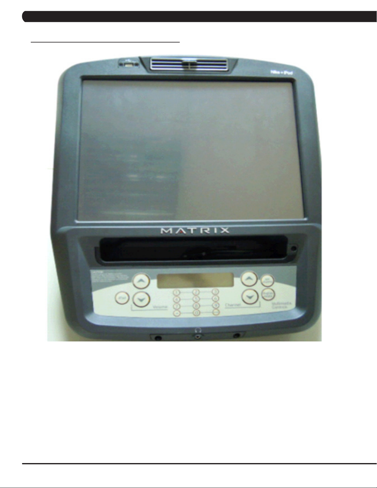
4.1 CONSOLE DESCRIPTION
The S7xe has a fully integrated touch screen display. All information required for workouts is explained on screen. Exploration of the interface
is highly encouraged. The information explaining how to program for various workouts will give an explanation about the contents of each
screen on the S7xe.
S7xe ENTERTAINMENT ZONE
iPOD®: Will take the user directly to the iPod screen to allow for iPod control and play list selection.
VOLUME UP / DOWN: Adjusts the volume output through the headphone jack of the integrated console TV or iPod output.
NUMBER KEYPAD: Allows for easy TV channel selection.
CHANNEL UP / DOWN: Allows for channel selection.
DISPLAY MODE: Allows user to cycle through console display options, iPod, TV, or profile display.
LAST CHANNEL: Allows the user to cycle between the current channel and the previous channel viewed.
8

CHAPTER 4: CONSOLE OVERLAY AND WORKOUT DESCRIPTION
4.2 WORKOUT SETUP STEPS - MANUAL
GO - Press to immediately begin a workout. Workout, resistance
level, and time will automatically go to default settings. Pressing
GO will not prompt user for age, weight, or level settings.
1) Start stepping and press GO on the display to begin your
workout. 2) The display will read 3, 2, 1, and then the program will
begin.
MANUAL - Manual allows the user to input more information
while defining their own workout. Calorie expenditure will be more
accurate when inputting information in Manual than by pressing GO.
1) Start stepping and press MANUAL on the display.
2) Select LEVEL on the display and follow the prompts to set.
3) Select TIME on the display and follow the prompts to set.
4) Select WEIGHT on the display and follow the prompts to set.
5) The display will read 3, 2, 1, and then the program will begin.
4.3 WORKOUT SETUP STEPS - LEVEL BASED
RANDOM - A level based workout that randomly adjusts the
resistance of the machine.
1) Start stepping and press RANDOM on the display.
2) Select LEVEL on the display and follow the prompts to set.
3) Select TIME on the display and follow the prompts to set.
4) Select WEIGHT on the display and follow the prompts to set.
5) The display will read 3, 2, 1, and then the program will begin.
ROLLING HILLS - The Rolling Hills program is a level based
program that automatically adjusts the resistance level to simulate
real terrain.
1) Start stepping and press ROLLING HILLS on the display.
2) Select LEVEL on the display and follow the prompts to set.
3) Select TIME on the display and follow the prompts to set.
4) Select WEIGHT on the display and follow the prompts to set.
5) The display will read 3, 2, 1, and then the program will begin.
INTERVALS - The Intervals program is a level based program
that automatically adjusts the resistance of the machine from low to
high intensity settings at regular intervals.
1) Start stepping and press INTERVALS on the display.
2) Select LEVEL on the display and follow the prompts to set.
3) Select TIME on the display and follow the prompts to set.
4) Select WEIGHT on the display and follow the prompts to set.
5) The display will read 3, 2, 1, and then the program will begin.
FAT BURN - Fat burn is a level based program that is designed
to help users burn fat through various resistance level changes.
1) Start stepping and press the key next to FAT BURN.
2) Select the key next to LEVEL and follow the prompts to set.
3) Select the key next to TIME and follow the prompts to set.
4) Select the key next to WEIGHT and follow the prompts to set.
5) The display will read 3, 2, 1, and then the program will begin.
9
CHAPTER 4: CONSOLE OVERLAY AND WORKOUT DESCRIPTION
4.4 WORKOUT SETUP STEPS - FITNESS TEST
FITNESS TEST -The Fitness Test program is to monitor the
development of your cardiovascular system and measure your
fitness level based on your average heart rate during specific test
stages. When the 5 minute test is completed, the display provides
a fitness score.
1) Start stepping and press FITNESS TEST on the display.
2) Select AGE on the display and follow the prompts to set.
3) Select GENDER on the display and follow the prompts to set.
4) Select WEIGHT on the display and follow the prompts to set.
5) The display will read 3, 2, 1, and then the program will begin.
6) Once the workout is complete, the display will read the results
of the Fitness Test.
MEN'S OUTPUT TABLE FOR FITNESS TEST
AGE EXCELLENT GOOD ABOVE
AVERAGE
18-25 <79 79-89 90-99 100-105 106-116 117-128 >128
26-35 <81 81-89 90-99 100-107 108-117 118-128 >128
36-45 <83 83-96 97-103 104-112 113-119 120-130 >130
46-55 <87 87-97 98-105 106-116 117-122 123-132 >132
56-65 <86 86-97 98-103 104-112 113-120 121-129 >129
65+ <88 88-96 97-103 104-113 114-120 121-130 >130
AVERAGE BELOW
AVERAGE
POOR VERY
POOR
WOMEN'S OUTPUT TABLE FOR FITNESS TEST
AGE EXCELLENT GOOD ABOVE
AVERAGE
18-25 <88 85-98 99-108 109-117 118-126 127-140 >140
26-35 <88 88-99 100-111 112-119 120-126 127-138 >138
36-45 <90 90-102 103-110 111-118 119-128 129-140 >140
46-55 <94 94-104 105-115 116-120 121-129 130-135 >135
56-65 <95 95-104 105-112 113-118 119-128 129-139 >139
65+ <90 90-102 103-115 116-122 123-128 129-134 >134
AVERAGE BELOW
AVERAGE
POOR VERY
GOOD
10
CHAPTER 4: CONSOLE OVERLAY AND WORKOUT DESCRIPTION
4.5 WORKOUT SETUP STEPS - TARGET HEART RATE
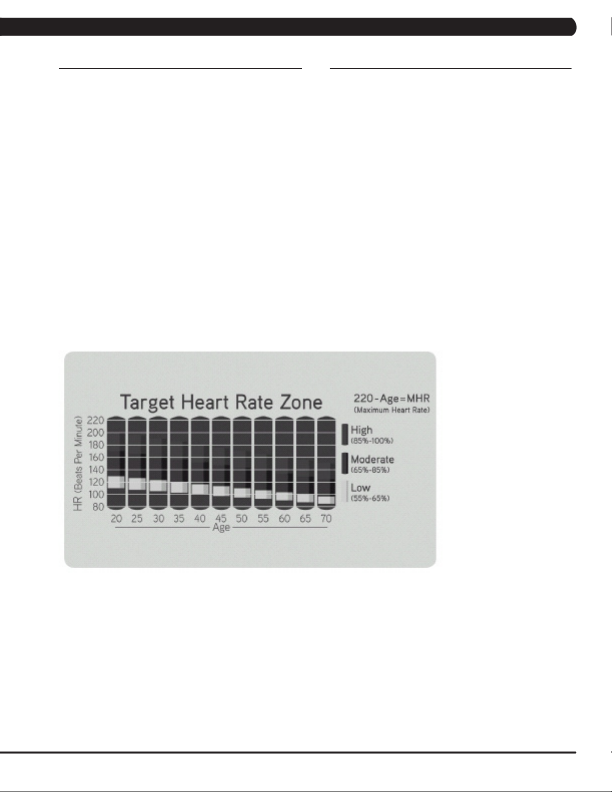
TARGET HEART RATE - The Matrix stepper comes with
standard digital contact heart rate sensors and are POLAR telemetry
compatible. The heart rate control workout mode allows the user
to program their desired heart rate zone, and the stepper will
automatically adjust the level based upon the user's heart rate.
The heart rate zone is calculated using the following equation:
(220-Age)8%=target heart rate zone. The user must wear a POLAR
telemetric strap or continually hold onto the contact heart rate grips
for this workout.
Locate the metal sensors on the handlebars of the stepper. Notice
that there are two separate pieces of metal on each grip. You must
be making contact with both pieces of each grip to get an accurate
heart rate reading. You can grab these sensors in any program to
view your current heart rate.
1) Start stepping and press TARGET HEART RATE on the display.
2) Select AGE on the display and follow the prompts to set.
3) Select PERCENTAGE OF HR on the display and follow the
prompts to set.
4) Select TIME on the display and follow the prompts to set.
5) Select WEIGHT on the display and follow the prompts to set.
6) The display will read 3, 2, 1, and then the program will begin.
4.6 WORKOUT SETUP STEPS - CONSTANT WATTS
CONSTANT WATTS - Constant Watts is a unique program
that allows you to vary your cadence or RPM and the stepper's
resistance level will adjust accordingly to your selected goal. The
quicker you step, the less resistance for the goal selected.
1) Start stepping and press the CONSTANT WATTS key.
2) Select WATT on the display and follow the prompts to set.
3) Select TIME on the display and follow the prompts to set.
4) Select WEIGHT on the display and follow the prompts to set.
5) The display will read 3, 2, 1, and then the program will begin.
11
CHAPTER 5: MANAGER MODE
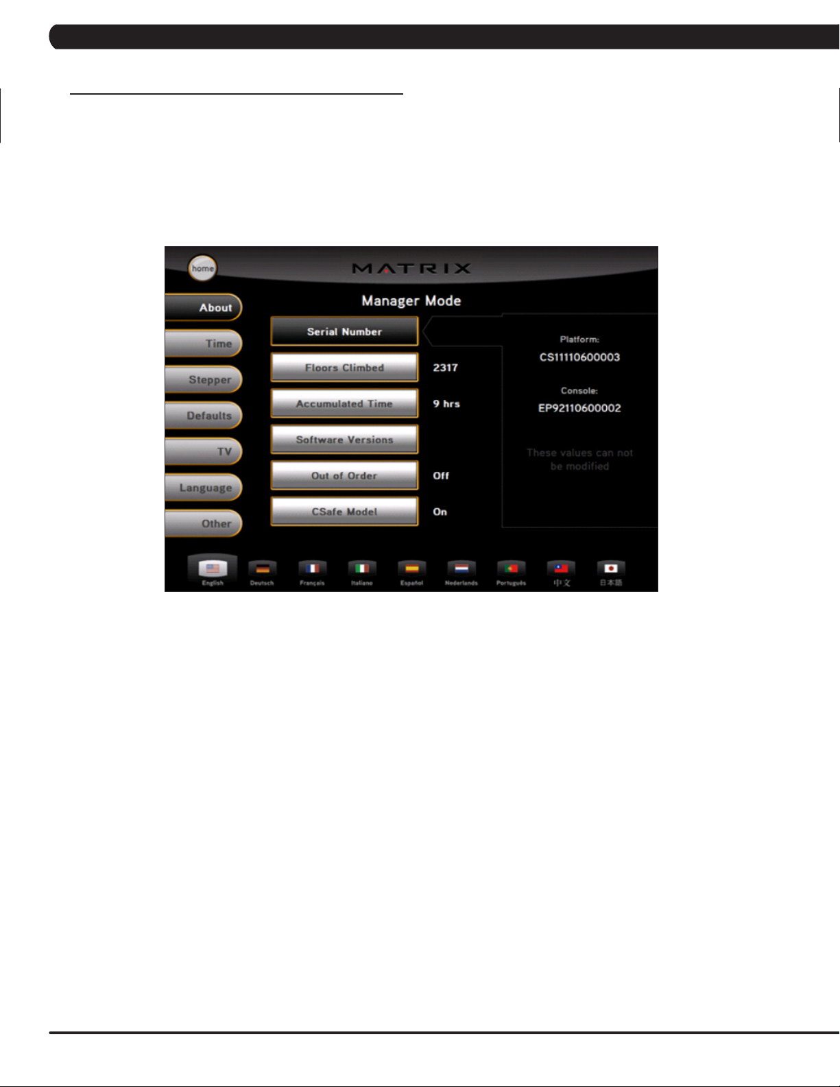
5.1 MANAGER MODE OVERVIEW
The Manager's Custom Mode allows the club owner to customize the stepper for the club.
1) To enter Manager Mode, press ENTER, 1, 0, 0, 1, ENTER on the lower display. Manager Mode will appear on the display (Figure A).
2) Follow the prompts to change the desired setting.
3) Press the ENTER key once the desired setting is correct to save.
4) Press HOME to return to normal operation. NOTE: If a setting has been changed, the unit and console power should be reset. Cycle the
power switch, and press and hold the CHANNEL UP and CHANNEL DOWN keys for 3-5 seconds to reset the console power.
FIGURE A
12
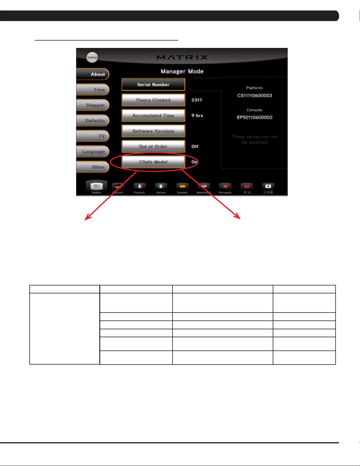
5.2 MANAGER MODE - ABOUT TAB
CHAPTER 5: MANAGER MODE
S7xe-02-C or S7xe-01-C - If the unit has the old MMM
board, the CSafe Model should be set for Off (even if
the MMM console is replaced).
MANAGER MODE
About
FUNCTION & DEFAULTS DESCRIPTIONS MODIFIED
Serial Number This option displays the serial number of the
Accumulated Distance Total distance on the unit since production. Cannot be modified.
Accumulated Time Total time on the unit since production. Cannot be modified.
Software Versions Software version. Cannot be modified.
Out of Order
Default: Off
CSafe Model Default: On This option controls whether the console is
S7xe-03-C - If the unit has the LMM board, the CSafe
Model should be set for On. If the unit has an LMM
board, there will usually be a USB port on the front of
the console.
platform and console. See Service Mode to
edit the serial numbers.
This option allows the club to show the unit
"out of order" if an error is present.
Fitlinxx compatible.
Cannot be modified.
On / Off
On / Off
13
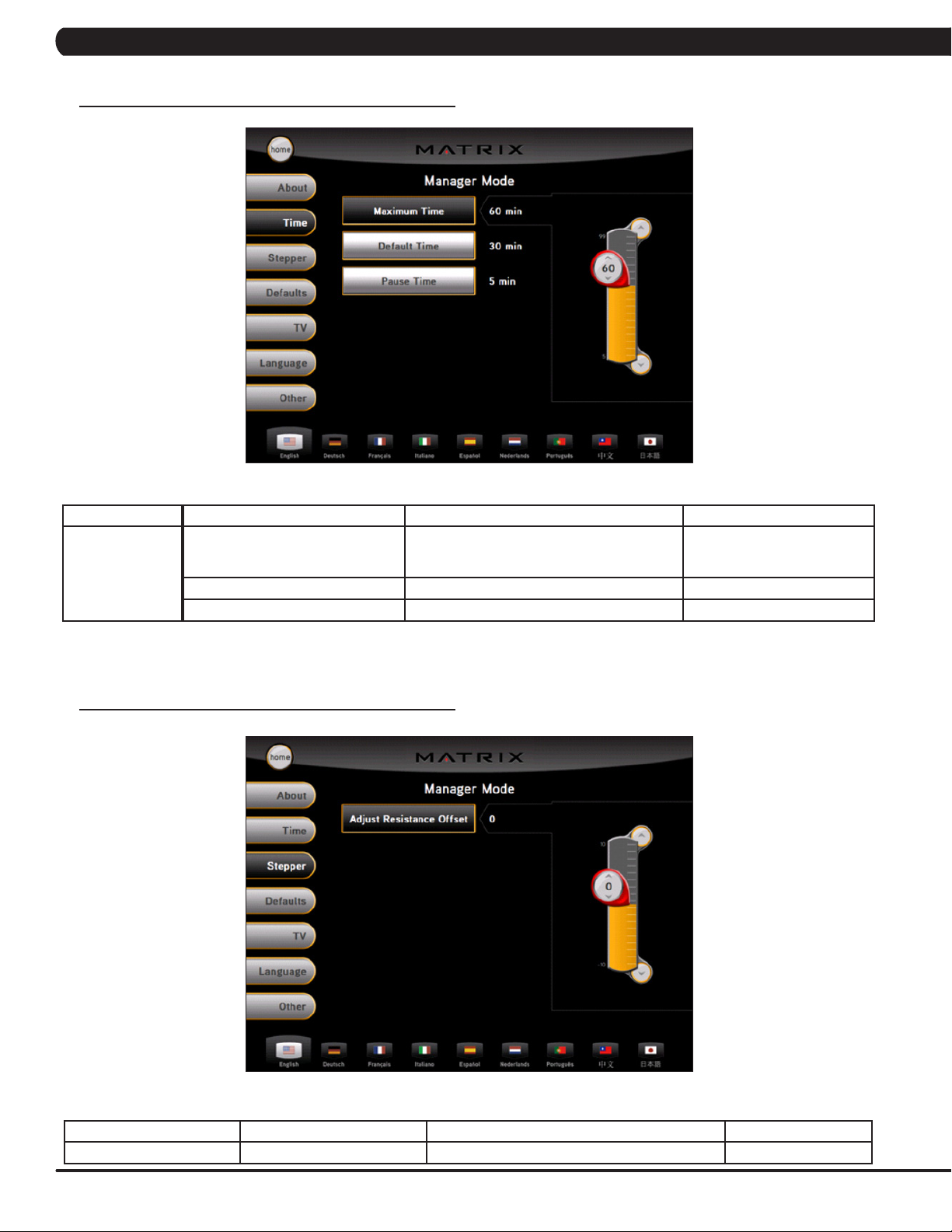
5.3 MANAGER MODE - TIME TAB
CHAPTER 5: MANAGER MODE
MANAGER MODE
Time
5.4 MANAGER MODE - STEPPER TAB
FUNCTION & DEFAULTS DESCRIPTIONS MODIFIED
Maximum Time
Default: 60 Minutes
Default Time Default: 30 Minutes This option controls the default program time. Max: Max Time Min: 5 Minutes
Pause Time Default: 5 Minutes This option controls the default pause time. Max: 10 Minutes Min: 1 Minute
This option allows the club to set the maximum
workout duration limits during peak and non
peak hours.
Maximum: 99 Minutes
Minimum: 5 Minutes
MANAGER MODE FUNCTION & DEFAULTS DESCRIPTIONS MODIFIED
Stepper Adjust Resistance offset This option is to adjust the resistance offset. -10 to 10
14
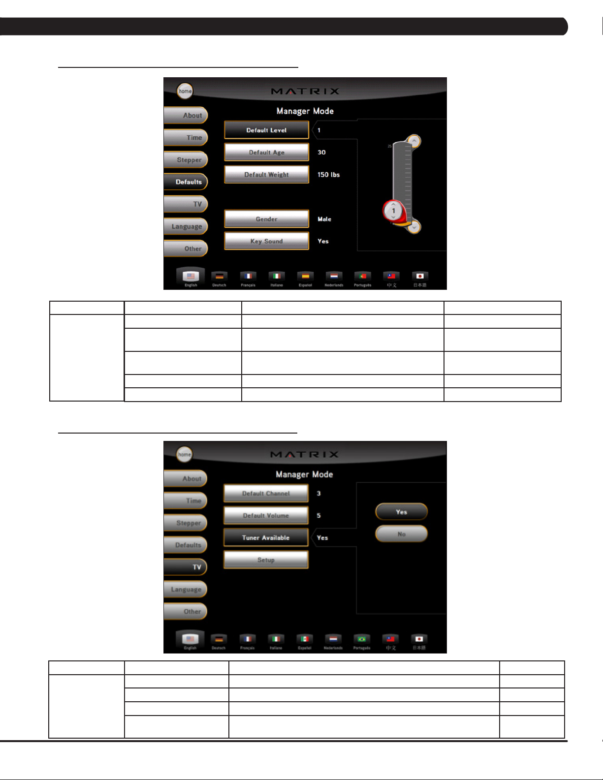
5.5 MANAGER MODE - DEFAULTS TAB
CHAPTER 5: MANAGER MODE
MANAGER MODE
Defaults
5.6 MANAGER MODE - TV TAB
FUNCTION & DEFAULTS DESCRIPTION MODIFIED
Level Default: 1 This option controls the default program level. Max: 1 Min: 20
Age Default: 30 This option controls the default user's age used in the
Weight Default: 150 lbs / 68 kgThis option controls the default weight used in the
Gender Default: Male Setting the user as Male or Female. Male or Female
Key Sound Default: Yes This option allows sound when the keys are pressed. Yes or No
target HR calculations.
calorie calculations. Displayed in pounds or kilograms.
Max: 100 Min: 10
Maximum: 400 lbs / 182 kg
Minimum: 50 lbs / 22 kg
MANAGER MODE
TV
FUNCTION & DEFAULTS DESCRIPTIONS MODIFIED
Default Channel Default: 3 This option controls the default TV channel on start up. Channels 1-999
Default Volume Default: 5 This option controls the default TV volume on start up. Max: 17 Min: 1
Tuner Available Default Yes This option scans the local TV system for channels. N/A
Setup This option is used to set the TV tuner function. Press the "-: key to enter
this function.
On / Off
15
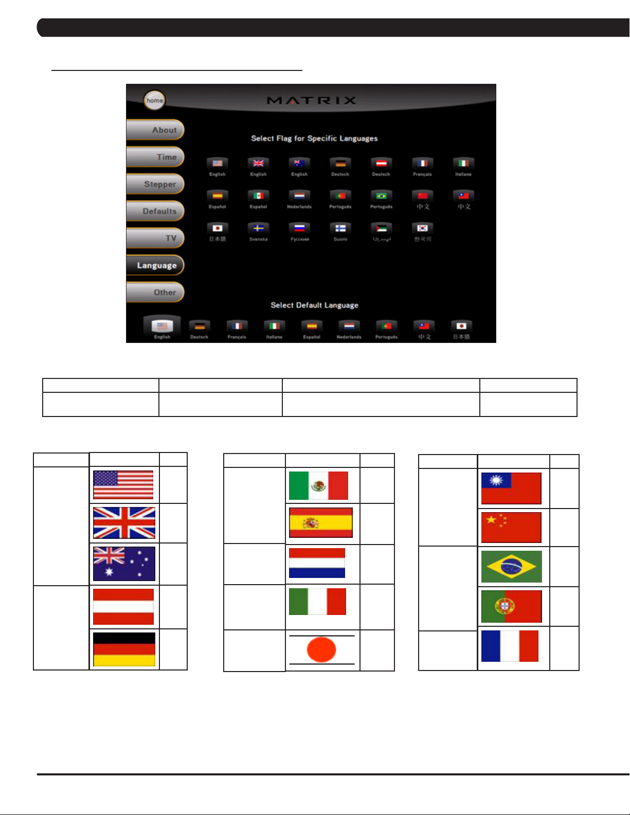
5.7 MANAGER MODE - LANGUAGE TAB
CHAPTER 5: MANAGER MODE
MANAGER MODE FUNCTION & DEFAULTS DESCRIPTIONS MODIFIED
Language Select default language. This option allows the user to select a flag for a
LANGUAGE
English
German
FLAG UNIT
Mile
Mile
KM
KM
KM
LANGUAGE
Spanish
Dutch
Italian
Japanese
specific language.
FLAG UNIT
KM
KM
KM
KM
KM
LANGUAGE
Chinese
Portuguese
French
N/A
FLAG UNIT
KM
KM
KM
KM
KM
16
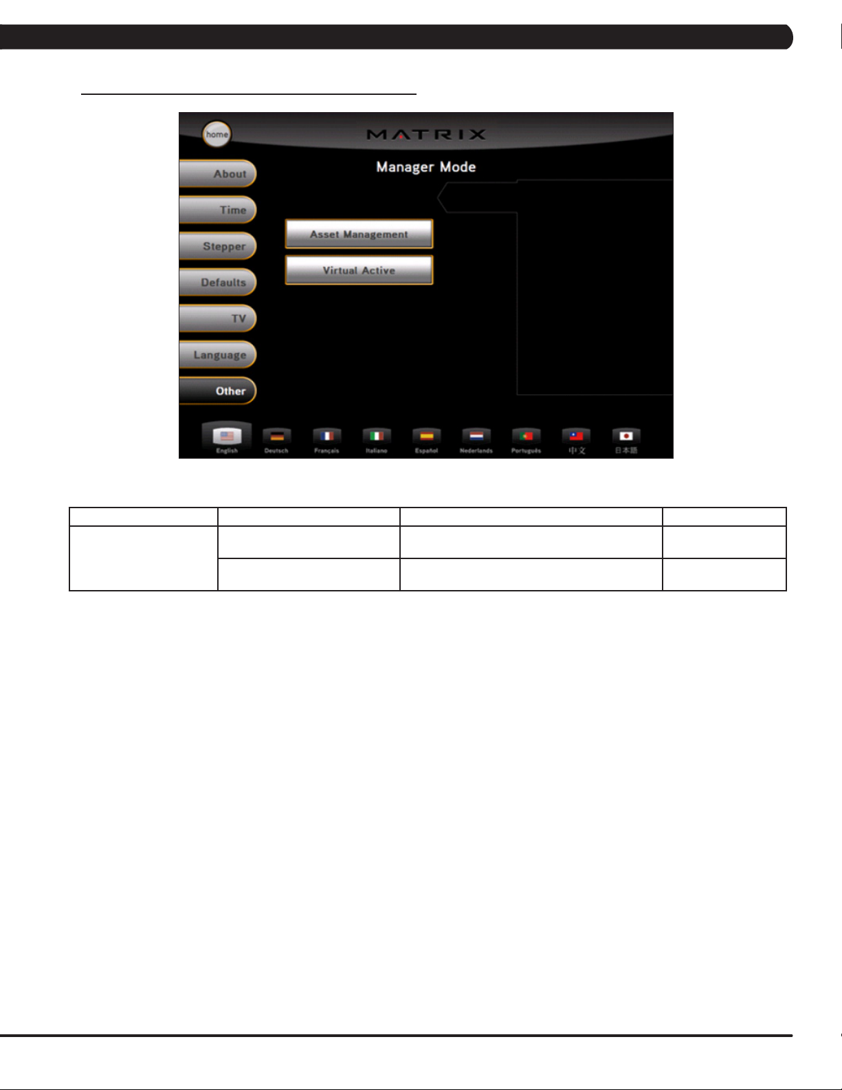
5.8 MANAGER MODE - OTHER TAB
CHAPTER 5: MANAGER MODE
ENGINEERING MODE
Other
FUNCTION & DEFAULTS DESCRIPTIONS MODIFIED
Asset Management
Default: Off
Virtual Active
Default: Off
This option allows fitness clubs to collect workout
data to a PC.
This option control the Virtual Active function. On or Off
On or Off
17
CHAPTER 6: ENGINEERING MODE
6.1 ENGINEERING MODE OVERVIEW
The Engineering Mode allows the club owner to keep track of the technical settings and error history for the stepper.
1) To enter Engineering Mode, press ENTER, 2, 0, 0, 1, ENTER on the lower display. Engineering Mode will appear on the display (Figure A).
2) Follow the prompts to change the desired setting.
3) Press the ENTER key once the desired setting is correct to save.
4) Press HOME to return to normal operation. NOTE: If a setting has been changed, the unit and console power should be reset. Cycle the
power switch, and press and hold the CHANNEL UP and CHANNEL DOWN keys for 3-5 seconds to reset the console power.
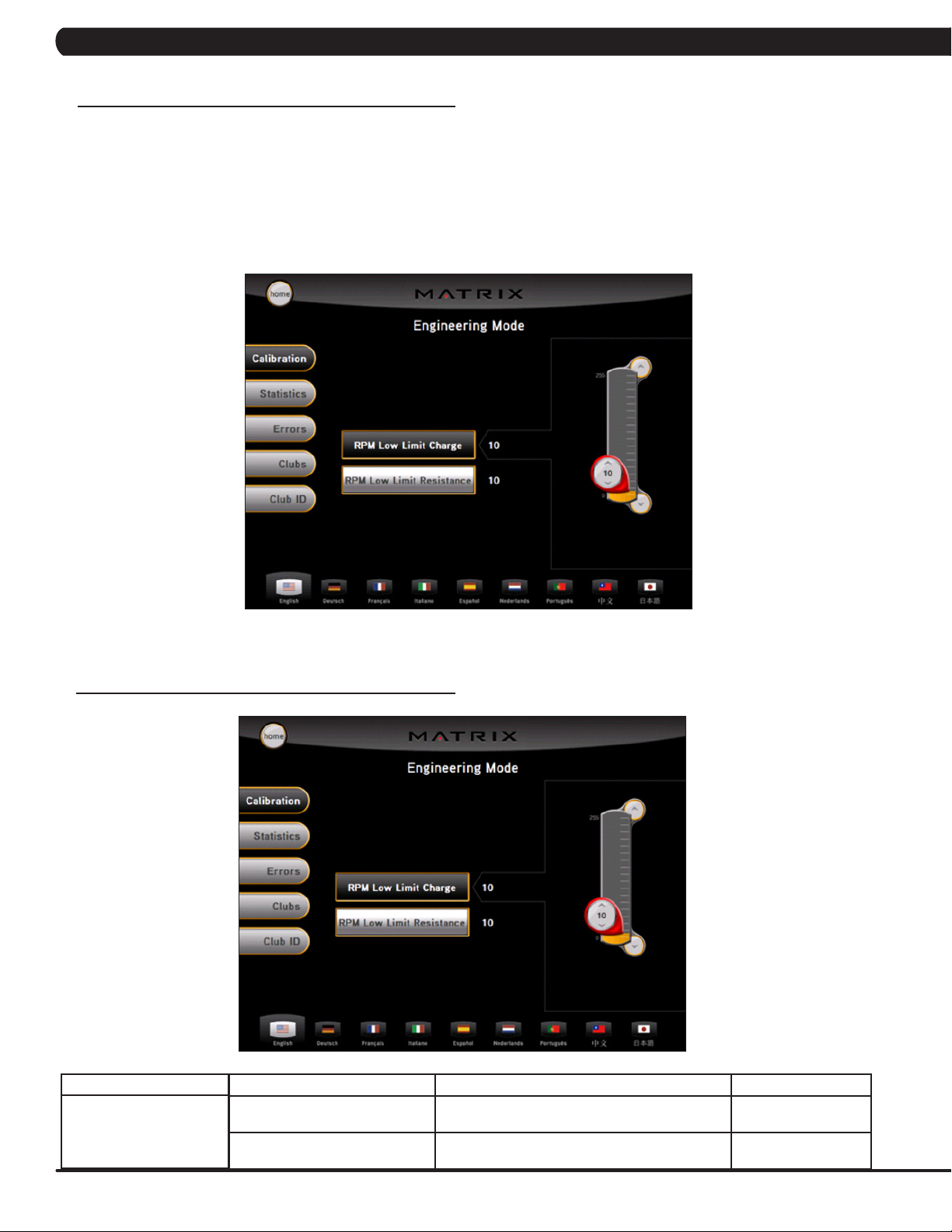
6.2 ENGINEERING MODE - CALIBRATION TAB
FIGURE A
18
ENGINEERING MODE
Calibration
FUNCTION & DEFAULTS DESCRIPTIONS MODIFIED
RPM Low Limit Charge:
Default: 10
RPM Low Limit Resistance
Default: 10
This option controls the RPM low limit to iPod
charge.
This option control the RPM low limit to show
resistance.
Range: 0 - 255
Range: 0 - 255
CHAPTER 6: ENGINEERING MODE
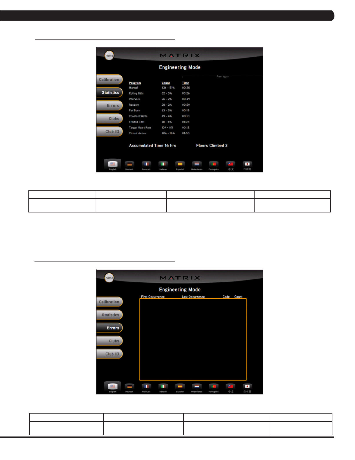
6.3 ENGINEERING MODE - STATISTICS TAB
ENGINEERING MODE FUNCTION & DEFAULTS DESCRIPTIONS MODIFIED
Statistics This option displays the workout
information for the unit.
6.4 ENGINEERING MODE - ERRORS TAB
N/A
ENGINEERING MODE FUNCTION & DEFAULTS DESCRIPTIONS MODIFIED
Errors This option displays the error code
history.
N/A
19

6.5 ENGINEERING MODE - CLUBS TAB
CHAPTER 6: ENGINEERING MODE
ENGINEERING MODE FUNCTION & DEFAULTS DESCRIPTIONS MODIFIED
Clubs
Default: MATRIX
6.6 ENGINEERING MODE - CLUB ID TAB
This option allows the club to select a screen
header from a list.
N/A
20
ENGINEERING MODE FUNCTION & DEFAULTS DESCRIPTIONS MODIFIED
Club ID This option records the Club ID of
the fitness facility.
N/A
 Loading...