

Matrix Elements VB-800, Vintage British Eight Hundred Field Manual

guitar amplification
WWW.MATRIXAMPLIFICATION.COM
made in britain, heard worldwide

Thank You
Congratulations on the purchase of your new Matrix Elements product.
Matrix amplifiers are the result of many decades of experience in the
design of exceptionally robust and reliable amplifiers.
They are designed to breathe life into your sound, by controlling your
speakers with exacting authority through the uncompromising delivery
of clean, undistorted power, from a package which is smaller and
lighter than you might expect for the performance it delivers.
This manual will help you to get the most from your amplifier. For
maximum benefit, it is recommended that all instructions and warnings
are carefully read. Also be sure to read the notices regarding correct
wiring of output connectors as this impacts the operation of the
amplifier.
For warranty service, please retain your receipt and all packaging that
comes with the amplifier, as it has been specifically designed to
transport the amplifier safely.
Unpacking
Please unpack and inspect your new amplifier for any damage that may
have occurred during transit. If damage is found, notify the carrier
immediately.
Note: PLEASE RETAIN ALL FACTORY PACKAGING FOR ANY FUTURE
POSTAL TRANSIT.
1

CAUTION:
OBSERVE ALL SAFETY AND USAGE INSTRUCTIONS TO AVOID POSSIBLE
DAMAGE TO EQUIPMENT AND EXPOSURE TO HAZARDS. THIS SYMBOL
UNIVERSALLY FLAGS CAUTION NOTICES
LETHAL VOLTAGES PRESENT AT SPEAKER, CABLE AND AMPLIFIER
TERMINALS; ENSURE ALL WIRING IS SAFE AND CORRECT BEFORE USE. THIS
SYMBOL ALSO UNIVERSALLY FLAGS ELECTRICAL HAZARDS
DO NOT OPEN UNIT; LEAVE ALL INTERNAL SERVICE OPERATIONS TO A
QUALIFIED TECHNICIAN. THIS PRODUCT IS CAPABLE OF PRODUCING SOUND
PRESSURE LEVELS WHICH MAY DAMAGE HEARING. THE USER IS
RESPONSIBLE FOR EXPOSURE LEVELS AND USE OF HEARING PROTECTION.
OPERATING ENVIRONMENT:
The amplifier is designed for use in environments which protect it from rain,
unusually high air humidity and temperature.
Place on a surface where it cannot be easily dislodged, potentially causing damage
to the unit or injury to a person. Ensure that the location will not expose the
amplifier to spillage of liquids/drinks, sprays/vapours or high humidity.
Ensure the amplifier is installed in a place which is not subject to abnormally high
temperatures and maintain sufficient ventilation to prevent overheating.
For temporary use outside, apply similar caution; however careful to ensure
placement accounts for changing weather conditions and that extreme
wind/rain/heat will not find its way to the equipment.
When taking any equipment from a cold environment (unheated storage, vehicles,
etc), into a warm one, allow the equipment time to become acclimatised to the
ambient temperature, as condensation is likely to form in the amplifier, potentially
causing it to malfunction if put into service too soon.
Note: This equipment has been tested and found to comply with the limits for a Class B digital device,
pursuant to part 15 of the FCC Rules. These limits are designed to provide reasonable protection against
harmful interference in a residential installation. This equipment generates, uses and can radiate radio
frequency energy and, if not installed and used in accordance with the instructions, may cause harmful
interference to radio communications. However, there is no guarantee that interference will not occur in a
particular installation. If this equipment does cause harmful interference to radio or television reception,
which can be determined by turning the equipment off and on, the user is encouraged to try to correct the
interference by one or more of the following measures:
— Reorient or relocate the receiving antenna.
— Increase the separation between the equipment and receiver.
— Connect the equipment into an outlet on a circuit different from that to which the receiver is connected.
— Consult the dealer or an experienced radio/TV technician for help.
2
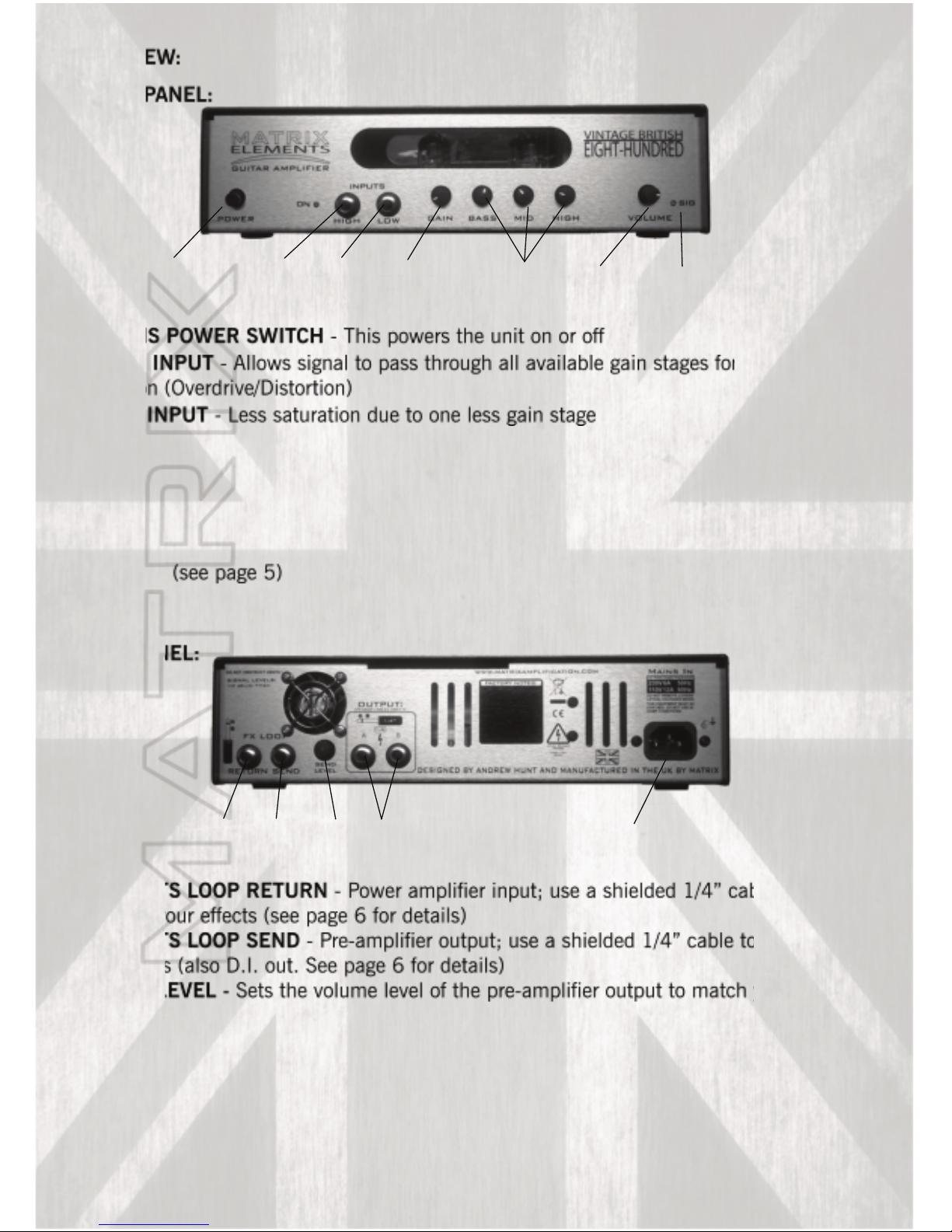
OVERVIEW:
FRONT PANEL:
1. MAINS POWER SWITCH - This powers the unit on or off
2. HIGH INPUT - Allows signal to pass through all available gain stages for more
saturation (Overdrive/Distortion)
3. LOW INPUT - Less saturation due to one less gain stage
4. GAIN CONTROL - Overdrive/Distortion level - The gain works from left to right
increasing in saturation as the control is turned clockwise
5. TONE CONTROLS - Each knob controls the different frequencies of the amplifier
6. VOLUME CONTROL - Controls the output volume level
7. SIGNAL INDICATOR - Gives indication of how much power the amp is providing at a
given load. (see page 5)
REAR PANEL:
1. EFFECTS LOOP RETURN - Power amplifier input; use a shielded 1/4” cable from the
output of your effects (see page 6 for details)
2. EFFECTS LOOP SEND - Pre-amplifier output; use a shielded 1/4” cable to connect to
your effects (also D.I. out. See page 6 for details)
3. SEND LEVEL - Sets the volume level of the pre-amplifier output to match your effects
(also D.I. pre-amp volume level. See page 6 for details)
4. OUTPUTS A/B - see page 6 for examples of suitable loading.
5. IEC INLET - Inlet for power cable (Do not remove the earth ground lug from the cable)
1
2
345
1
2
3
4
5
6
7
3
 Loading...