

Page 1
guitar amplification
made in britain, heard worldwide
MATRIX
MATRIX
POWER
on
POWER
on
POWER
on
POWER
on
BRIDGE
BRIDGE
BRIDGE
BRIDGE
MONO
MONO
MONO
MONO
AB
CHANNEL LEVELS
AB
CHANNEL LEVELS
AB
CHANNEL LEVELS
AB
CHANNEL LEVELS
ON
PROTECT
ON
PROTECT
ON
PROTECT
ON
PROTECT
SIGNALSIGNAL
SIGNALSIGNAL
SIGNALSIGNAL
SIGNALSIGNAL
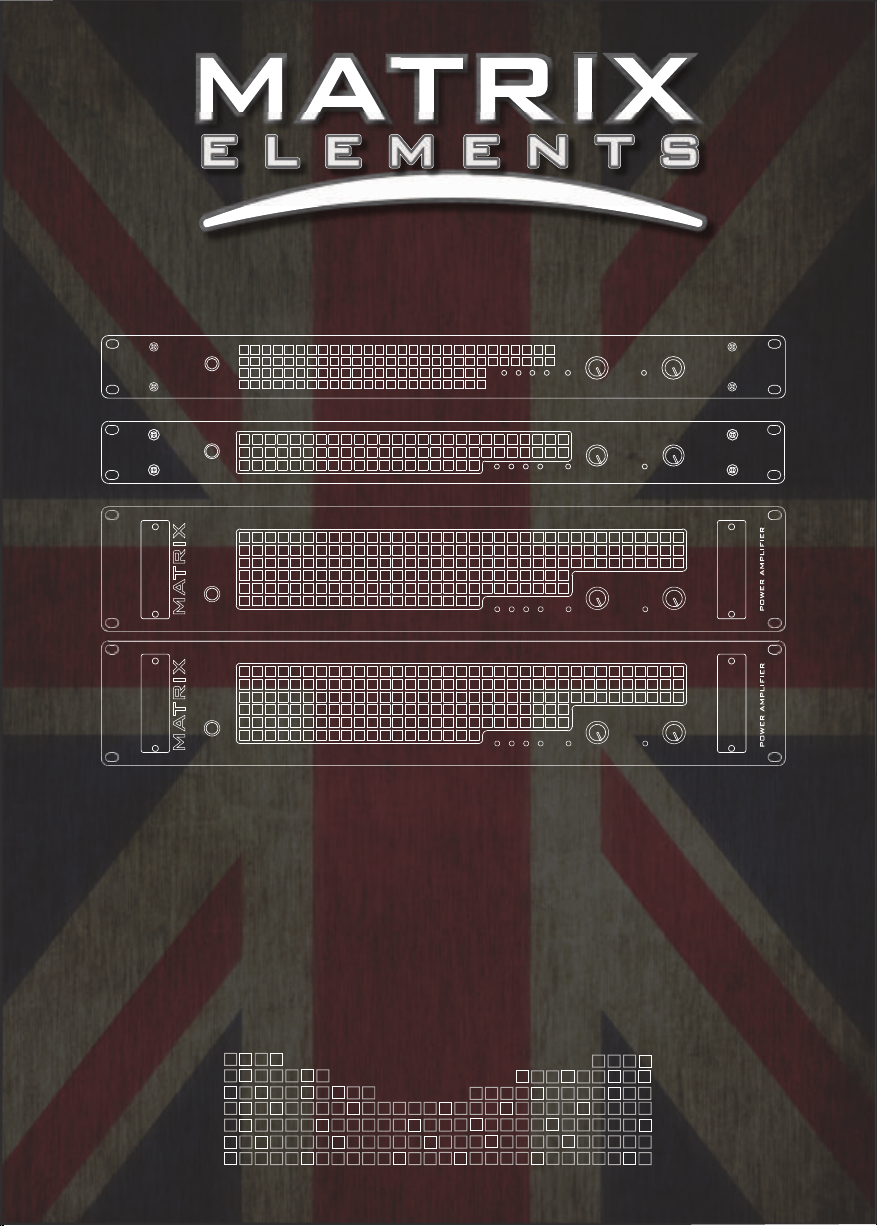
GT 800FX
POWER AMPLIFIER
GT1000FX
POWER AMPLIFIER
GT1000FX
GT1600FX
gt series amplifiers
user manual
models covered:
gt800fx, gt1000fx (1u & 2u),
gt1600fx
WWW.MATRIXAMPLIFICATION.COM
Page 2

CONTENTS:
1. Thank You & Unpacking.
PAGE:
1
Thank You
Congratulations on the purchase of your new
Matrix Professional Power Amplifier.
Matrix amplifiers are the result of many
decades of experience in the design of
exceptionally robust and reliable amplifiers.
They are designed to breathe life into your
sound, by controlling your speakers with
exacting authority through the uncompromising
delivery of clean, undistorted power, from a
package which is smaller and lighter than you
might expect for the performance it delivers.
This manual will help you to get the most from
your amplifier. For maximum benefit, it is
recommended that all instructions and
warnings are carefully read. Also be sure to
read the notices regarding correct wiring of
output connectors as this impacts the operation
of the amplifier.
For warranty service, please retain your receipt
and all packaging that comes with the
amplifier, as it has been specifically designed to
transport the amplifier safely.
Unpacking
Please unpack and inspect your new amplifier
for any damage that may have occurred during
transit. If damage is found, notify the carrier
immediately.
Note: A suitable mains lead is provided and can
be found packaged with the amplifier.
PLEASE RETAIN ALL FACTORY
PACKAGING FOR ANY FUTURE POSTAL
TRANSIT.
2. Safety Notices & FCC
Declaration.
3. Layout:
3.1 Front Panel.
3.2 Rear Panel.
4. Before You Start.
5. Getting Started, Powering
Up & Connections.
6. Set-Up Examples.
7. International Voltage
Selection.
8. Choosing Cables.
9. Troubleshooting.
10. Warranty.
11. Care & Contact Us.
12. Technical Specs.
13. CE Declaration.
14. Notes.
2
3-7
3-4
5-7
7
8-9
10-13
14
15
16-17
18
19
20
21
22
1
Page 3

CAUTION:
OBSERVE ALL SAFETY AND
USAGE INSTRUCTIONS TO AVOID
POSSIBLE DAMAGE TO
EQUIPMENT AND EXPOSURE TO
HAZARDS. THIS SYMBOL
UNIVERSALLY FLAGS CAUTION
NOTICES
LETHAL VOLTAGES PRESENT AT
SPEAKER, CABLE AND AMPLIFIER
TERMINALS; ENSURE ALL
WIRING IS SAFE AND CORRECT
BEFORE USE. THIS SYMBOL
ALSO UNIVERSALLY FLAGS
ELECTRICAL HAZARDS
DO NOT OPEN UNIT; LEAVE ALL
INTERNAL SERVICE OPERATIONS
TO A QUALIFIED TECHNICIAN.
THIS PRODUCT IS CAPABLE OF
PRODUCING SOUND PRESSURE
LEVELS WHICH MAY DAMAGE
HEARING.
THE USER IS RESPONSIBLE FOR
EXPOSURE LEVELS AND USE OF
HEARING PROTECTION.
OPERATING ENVIRONMENT:
The amplifier is designed for use in environments which
protect it from rain, unusually high air humidity and
temperature.
Place on a surface where it cannot be easily dislodged,
potentially causing damage to the unit or injury to a person.
Ensure that the location will not expose the amplifier to
spillage of liquids/drinks, sprays/vapours or high humidity.
Ensure the amplifier is installed in a place which is not
subject to abnormally high temperatures and maintain
sufficient ventilation to prevent overheating.
For temporary use outside, apply similar caution however,
careful to ensure placement accounts for changing weather
conditions and that extreme wind/rain/heat will not find its
way to the equipment.
When taking any equipment from a cold environment
(unheated storage, vehicles, etc), into a warm one, allow the
equipment time to become acclimatised to the ambient
temperature, as condensation is likely to form in the
amplifier, potentially causing it to malfunction if put into
service too soon.
Note: This equipment has been tested and found to comply
with the limits for a Class B digital device, pursuant to part
15 of the FCC Rules. These limits are designed to provide
reasonable protection against harmful interference in a
residential installation. This equipment generates, uses and
can radiate radio frequency energy and, if not installed and
used in accordance with the instructions, may cause harmful
interference to radio communications. However, there is no
guarantee that interference will not occur in a particular
installation. If this equipment does cause harmful
interference to radio or television reception, which can be
determined by turning the equipment off and on, the user is
encouraged to try to correct the interference by one or more
of the following measures:
— Reorient or relocate the receiving antenna.
— Increase the separation between the equipment and
receiver.
— Connect the equipment into an outlet on a circuit different
from that to which the receiver is connected.
— Consult the dealer or an experienced radio/TV technician
for help.
2
Page 4
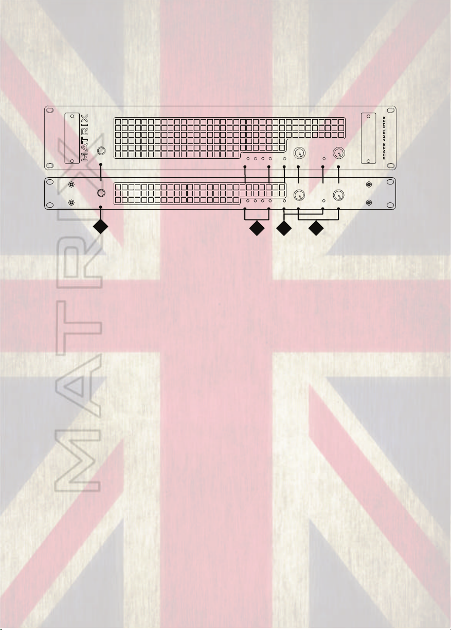
FRONT AND REAR PANEL LAYOUTS: 1U & 2U MODELS
The front and rear panels on 1U & 2U versions of the amps share the same
features and layouts.
1U MODEL (GT800 & GT1000) & 2U MODEL (GT1000 & GT1600)
POWER
on
MATRIX
POWER
on
1
(1) Power Switch
MONO
MONO
AB
AB
4
ON
BRIDGE
PROTECT
ON
BRIDGE
PROTECT
2
SIGNALSIGNAL
CHANNEL LEVELS
SIGNALSIGNAL
CHANNEL LEVELS
3
GT x x x FX
GT x x x F X
POWER AMPLIFIER
This switch controls the power supply to the amplifier.
(2) Indicator Section, Status:
a. Power Indicator
This indicator shows when the amplifier is on and is receiving power.
b. Parallel Mono Mode Indicator
This indicator shows if (parallel) MONO mode is selected on the rear panel.
For channel pair A and B only Input A will be used to drive both channels. Full
independent level control of the amplifier output stages is still possible via the Gain
controls.
c. Bridged Mono Mode Indicator
This indicator shows if Bridged mode is selected on the rear panel. It is most
important that this indicator is not illuminated unless bridged mode is required. This
is because when bridged mode is selected, Channel A will be out of phase with
Channel B. This will result in poor bass response and an unsatisfactory sound if left
and right outputs are used. In this mode Channel A controls the output level.
d. Protect Indicator
This indicator lights briefly during the power up cycle and also lights should a
fault occur. Illumination of the protect indicator, shows that the output of the
amplifier has been disconnected by means of an internal relay to protect connected
speaker systems from being damaged by the fault.
3
Page 5
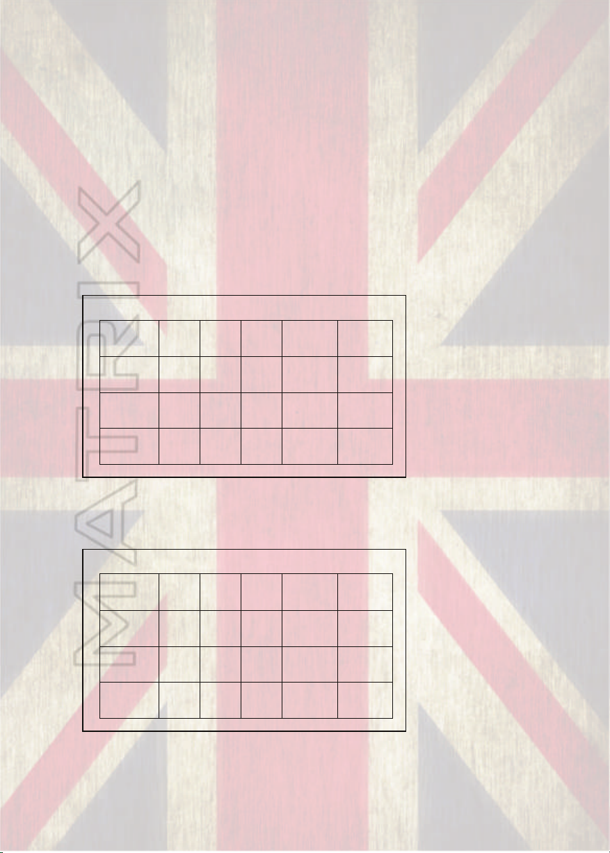
(3) Gain Controls
4
Ohms
8
Ohms
16
Ohms
8 Ohms
(Bridged)
16 Ohms
(Bridged)
GT800FX
50
30
15
100
60
GT1000FX
60
40
20
120
80
GT1600FX
100
60
30
200
120
4
Ohms
8
Ohms
16
Ohms
8 Ohms
(Bridged)
16 Ohms
(Bridged)
GT800FX
100
60
30
200
120
GT1000FX
120
80
40
240
160
GT1600FX
200
120
60
400
240
The level of each Channel is individually adjusted by these controls.
Rotating these controls fully clockwise, results in no attenuation to the incoming audio
signals.
(4) Indicator Section, Signal levels:
These show the (Peak) output level of the amplifier for each channel, in both
Stereo and Mono modes. These will start to illuminate when a signal is present at the
speaker sockets when driven above a threshold of approximately -9db. Note that for
levels below this amount the led may not illuminate. The signal level lights are useful in
indicating how much power is being sent to the speaker connected. The -9db threshold
relates to approximately 12.5% of the amps available power at the load it is connected
to. The table below gives the ratings at -9db for typical impedances connected.
Signal lights starting to blink at -9db
For every increase of 3db that occurs, a doubling of the power is needed, so to that
effect, when the signal lights start to stay permanently on at -6db the power the amp
produces is doubled. Most stage volumes will occur somewhere between the two
Signal lights starting to stay on at -6db
but if you’re happy with the volume levels and the signal lights are not lighting up,
that’s fine!
4
Page 6

1U MODEL (GT800 & GT1000) & 2U MODEL (GT1000 & GT1600)
WWW.MATRIXGUITARAMPLIFICATION.COM
_
+
For A+B Bridged Output Use Socket Marked X
For Bridged Output Only !
NL2
NL2
1/4”
1/4”
1:X
1:A
X
DESIGNED BY ANDREW HUNT AND MANUFACTURED IN THE UK BY MATRIX
1:A
X
DESIGNED BY ANDREW HUNT AND MANUFACTURED IN THE UK BY MATRIX
6
NL2
1/4”
1/4” & SPKN. OUT
1/4” & SPKN. OUT
+
_
AC Power Supply Requirement
50 to
230V 6A
110V 12A
60Hz
DO NOT REMOVE COVERS
LETHAL VOLTAGES INSIDE.
THIS EQUIPMENT MUST BE
EARTHED.
DO NOT USE IN
DAMP CONDITIONS.
AC Power Supply Requirement
50 to
230V 6A
110V 12A
60Hz
DO NOT REMOVE COVERS
LETHAL VOLTAGES INSIDE.
THIS EQUIPMENT MUST BE
EARTHED. DO NOT USE IN
DAMP CONDITIONS.
WWW.MATRIXGUITARAMPLIFICATION.COM
+0 dBu/0.775V
+0 dBu/0.7V
8
+
Both Input and Output Connectors
Accept 1/4” Jackplugs in Addition to XLR/NL2
1/4” & XLR IN
+
1/4” & XLR IN
7
For Bridged Output Use Socket Marked X - For Bridged Output Only !
5
(5) Cooling Fan Outlets
Hot air exits here. Make sure all rear (and front) ventilation paths are
free from obstruction and air flows freely, otherwise the amplifier will
trip into thermal protect mode prematurely and in some extreme
circumstances damage may occur.
(6) Output Connectors
The Output sockets are Neutrik® Speakon / 1/4” combi connectors.
They accept both Neutrik® NL2FC & 1/4” jack plugs (NL4FC
accepted, however only terminal pair 1 carry signals). Avoid inferior
alternatives, as they may present numerous hazards due to less than
ideal construction.
9
When inserting speakon plugs turn clockwise until you hear it
click; This ensures correct connection has been made. To remove, pull
back the levered tab and turn anti-clockwise.
Ready-made, sensibly priced, quality interconnection leads
suitable for use with the amplifier should be easy to source. However,
with sufficient skill, it is possible to make/modify leads for the task.
•Only the first two pins (+1 and -1) are used in this amplifier.
•When utilising the 1/4” output option the centre pin (Tip) is
connected to +1 & the outer sheath (Sleeve) is connected to
-1.
•For STEREO/MONO operation, unmodified “off the shelf”
cables will usually work fine.
•For BRIDGED MONO mode, Output is exclusively available
from OUTPUT X, do not use at any other time.
5
Page 7

CAUTION: Whilst we recommend that Neutrik speakon connections
are always used for the safest way of connecting to the amplifier, the
option is also provided to use 1/4” jack connections with these
outputs. Take extra care when connecting leads to ensure that these
are not accidentally connected to the inputs and outputs of other
equipment not designed specifically to do so, otherwise damage to
equipment is likely to occur.
Take extra care with 1/4” jack speaker connections, the exposed plug end
can present an electric shock hazard, also never allow the outputs to be
shorted, equipment damage may occur. Finally, never use standard 1/4”
instrument leads for connection between amplifier and loudspeaker, choose a
quality speaker lead for this specific task for safe operation. and optimal
performance.
(7) Input Signal Sockets.
These are Neutrik® combined female XLR and 1/4" jack sockets.
For cable runs of under 12”, (ie. within a rack system) standard good quality
instrument leads should provide a similar level of RF shielding to XLR cables.
For longer cables runs, balanced cables (XLRs) are recommended.
(8) Output Mode Selector.
STEREO, MONO or BRIDGED (mono) Output can be selected using this
switch.
Take care to ensure the correct mode for your application is selected.
•In Stereo mode, channels A and B operate independently, when fed
with separate input signals. (Think of this as two separate mono amps
fed by their own input.)
•In Parallel (Mono) mode, Input A is connected to feed both amplifier
channel A and B. Input B is not used. Full independent level control
over each amplifier output channel remains possible. (This is useful if
you want to send the same mono signal to two separate cabs).
•In Bridged (Mono) mode, the input from channel A is fed out of phase
to channel B and combined to give a higher power mono output.
Note: Bridged Output X is used exclusively for this mode, do not
use at any other time. Using output channel A or B whilst
Bridged mode is selected will give a thin, out of phase sound,
lacking bass through those outputs.
6
Page 8
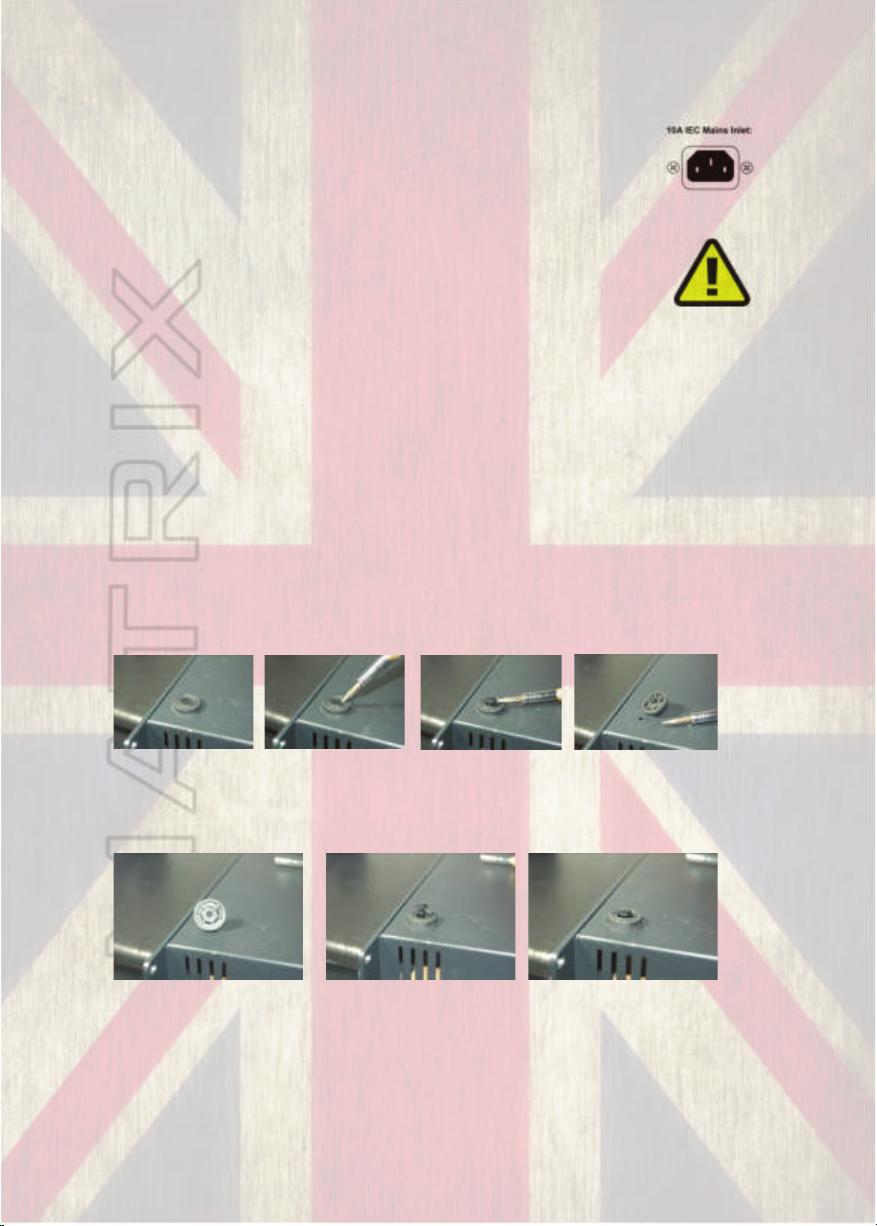
(9) Power Connection
Mains power is supplied to the amplifier by a standard 10 Amp IEC
mains socket.
An appropriate mains lead is supplied with the amplifier.
Note: The amplifier requires a stable power supply to function
as intended. Ensure that the power source (mains power
supply, generator, etc.) is suitable for this application and
adequate power is available. Poorly selected power sources
result in sub-optimal performance, increased likelihood of
tripping breakers, blowing fuses and in extreme situations
damage to equipment may occur.
BEFORE YOU START:
If you intend to rack mount your GT series amplifier you may want to
consider removing the rubber feet from the amplifier to allow maximum
room for other units that may share the rack space. This is a simple
process. Using a small flat bladed screwdriver gently prise the shiny plastic
insert up from the chassis which will enable the feet to be removed. Store
somewhere safe!!
1234
To replace the feet simply pull the plastic insert so the mechanism is closed,
line up the foot with the chassis hole and push into place.
123
7
Page 9

GETTING STARTED, POWERING UP & CONNECTIONS:
Your GT Series amplifier comes equipped with a power lead specific for the
requirements of your country. Use only the correct lead with the correct rated
fuse for your country’s power requirements. Use of an incorrect lead or fuse
rating could lead to damage of your amplifier.
NOTE: Unlike a Valve powered amplifier, it is not
necessary to connect a speaker (or load) to the amp
whilst it is powered on. Powering on or operation of the
amp without a speaker or load attached will NOT damage
the amplifier.
1.Connect the supplied mains power lead to the IEC inlet on the rear of the
amp.
2. Connect the signal source (this can be your pre-amp, modelling device or
main outs from your effects unit) to the inputs on the rear of the amp. If you
are running in mono from your source, then only use one channel of the amp
and keep the amp in stereo mode. Note: If you are running the Matrix amp
as part of a wet/dry or wet/dry/wet system then make sure the connections
between your ampfier or source are in place to the effects system you intend
to use before feeding the signal to the Matrix amp.
3. Connect the GT amplifier to a speaker or cabinet with a good quality
speaker cable. Never use a screened (shielded) guitar cable for this as you
may damage the cable and the amplifier. The GT-series amps will accept
various standard impedance cabinets and even non standard but bear in
mind that the total load must NOT exceed 4 ohms per channel (or 8 ohms
in bridged mode).
4. Making sure that the amp is turned off at this point, power up your signal
source (this prevents any unwated signal noise transmitted to your
speaker(s). Now with the volumes on the amp all the way down, power on
the amplifier via the power switch located on the front. You may hear a
slight “thump” as the unit is powered on. This is perfectly normal.
5. Adjust the controls of the input source to a required level (ideally 0db or
.775v) and steadily increase the GTs volume until a sufficient level is
achieved.
6. Adjust the levels of the relevant volume controls on the Matrix amp until
desired volume is achieved.
8
Page 10

NOTE: The Matrix’s volume controls are basically
attenuators. That means that to achieve full power at
their specified load they requires a signal of .775v
(0db) and the volume knobs up full. If you put a higher
level signal into the amp, it will achieve it's full power
rating earlier than at full volume position and inversely,
if you put a lower level signal in, say -6db, the amps
full volume will always be -6db of full power rating.
If your volume is lower than expected even with the Matrix amp on full
then look to increse the signal level going into the amp. This could be the
individual patch volume or the master volume of the unit or indeed the
send level of a preamp. Be aware of the noise floor of a unit as well.
Turning something up full will usually turn up the amount of noise the unit
generates. The Matrix units are obviously designed to be turned up full
and have a low level of noise/distortion but you may experience issues if
you turn up the signal being fed into the Matrix too much and have the
volume of the amp set too low.
Important Notice regarding connection to multiple
input and switchable input cabinets.
Care must be taken when connecting the amp to any
cabinet that has more than one jack plug or socket or
features switchable stereo/mono operating modes.
Certain cabinets are known to have more than one
socket but are not stereo capable cabs.
Orange® 2x12 and 4x12 cabs for instance have two unlabeled parallel
inputs. Connecting the amplifier to both inputs effectively shorts the
amplifiers outputs and will cause damage to the amplifier. This will not
be covered under warranty.
Similarly, cabinets which feature stereo/mono switchable inputs
(Marshall® style) must always be switched to stereo operation when
both channels of the amplifier are connected to it. Switching to mono
mode will turn the input into a parallel output and again effectively link
and short the amps channel outputs together. If you are unsure of your
cabinets’ specifications, please refer to the manufacturer’s instructions
or consult a qualified technician for guidance. Care must also be taken
with Mesa® style cabinets to use the applicable socket for stereo or
mono and manually switch to the correct one(s).
If in doubt consult your cabinets manual or relevant support page.
9
Page 11
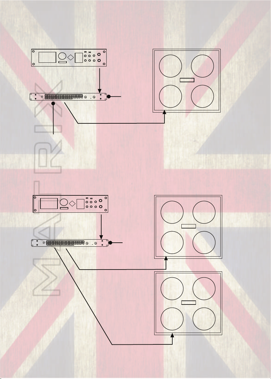
SOME TYPICAL SET-UP EXAMPLES:
Modelling System/Pre-amp/Multi FX in Mono To Single Cab
Main Mono/L Out to
Input A on Matrix Amp
MATRIX
POWER
on
ON
BRIDGE
PROTECT
GT FX
POWER AMPLIFIER
AB
SIGNALSIGNAL
CHANNEL LEVELS
MONO
Matrix mode
switch set to
Stereo
Matrix Output A to Mono Input of Cab
NB: No need to connect
a load to Output B
Modelling System/Pre-amp/Multi FX in Mono To Two Cabs
Main Mono/L Out to
Input A on Matrix Amp
MATRIX
POWER
on
ON
BRIDGE
PROTECT
GT FX
POWER AMPLIFIER
AB
SIGNALSIGNAL
CHANNEL LEVELS
MONO
Matrix mode
switch set to
Parallel
Matrix Output A to Mono Input of Cab 1
Matrix Output B to Mono Input of Cab 2
10
Page 12
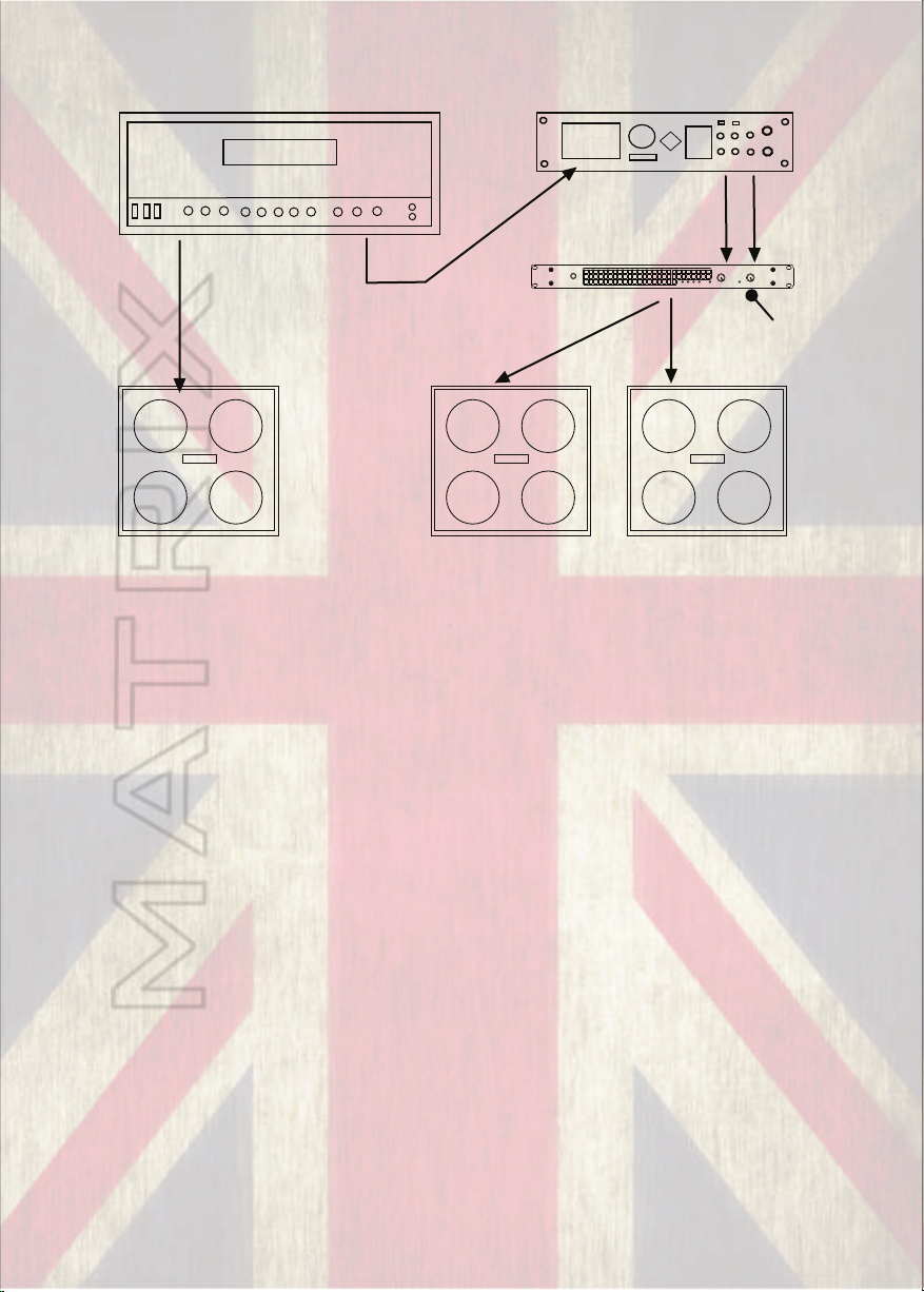
Wet/Dry/Wet Rig
Stereo L&R Out
from FX to Input
A&B on Matrix
Amp
FX Send or Line Out from Amp to
Input of Effects Unit
Main Speaker Out from Amp to
Dry Cab (no effects)
POWER
MATRIX
Outputs A&B from Matrix to Wet
Cabs (effected signal)
on
ON
BRIDGE
PROTECT
AB
SIGNALSIGNAL
CHANNEL LEVELS
MONO
Matrix in Stereo
Mode
GT FX
POWER AMPLIFIER
NOTE: The above system can also be adapted to run the Matrix as a “slave”
amp. Take care that the Matrix amp receives only a line level signal and not
a signal direct from the main amps speaker out otherwise damage will
occur. This can be from the amps line out or effects send or from a suitable
ISO/Load box with a line out facility. Care must also be taken to ensure the
main amp still has a “load” attached to it either in the form of a cabinet or
suitable load box.
11
Page 13
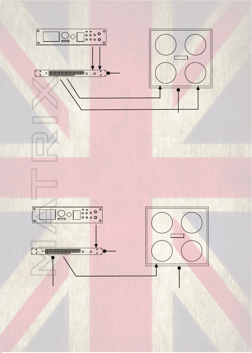
Modelling System/Pre-amp/Multi FX in Stereo To Stereo Single Cab
Main Stereo L&R Out
to Input A&B on Matrix
Amp
MATRIX
POWER
on
ON
BRIDGE
PROTECT
GT FX
POWER AMPLIFIER
AB
SIGNALSIGNAL
CHANNEL LEVELS
MONO
Matrix mode
switch set to
Stereo
Matrix Output A to Stereo Input of Cab
Matrix Output B to Stereo Input of CabNB: Ensure cab is
stereo capable and is
switched to stereo
mode
NOTE: The above system can also be run to two separate mono cabs to
achieve a wider stereo depth of field.
If using a stereo/mono switchable cab, always check your cab is in
stereo mode before connecting both outputs to it!
Bridged Mode (High Powered Mono 8 Ohms Minimum)
Main Mono/L Out to
Input A on Matrix Amp
POWER
MATRIX
on
NB: Only use Output X
for Bridged Mode
GT FX
POWER AMPLIFIER
AB
SIGNALSIGNAL
ON
CHANNEL LEVELS
MONO
BRIDGE
PROTECT
Matrix Output X to Mono Input of Cab
Matrix mode
switch set to
Bridged
12
Ensure cabinet is a minimum of 8 ohms or
over (8 or 16 for instance) or the amp will go
into protect mode. Bridged mode delivers
much more power so also ensure your cab is
capable of handling the extra wattage!
Page 14
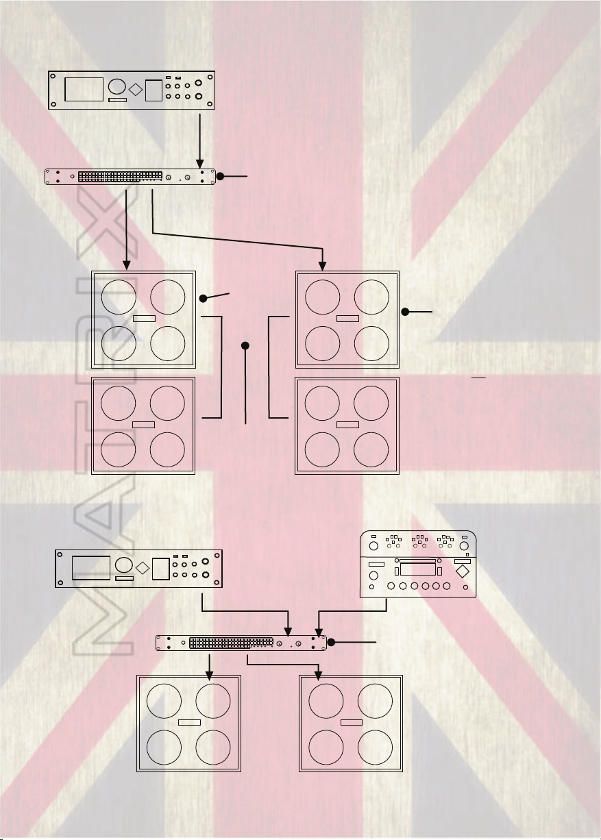
More Complex Systems with Mismatched Loads or Daisy Chained Cabs
Note: Depending on your
modelling system you can also
run hybrid systems from each
channel of the amp comprising
traditional guitar cabinets and
FRFR systems for maximum
realism and tonal possibilities.
This cab could be 8 ohms
and the bottom cab could
be 16 ohms giving a
combined impedance of 5.3
ohms total.
R total = (R1xR2) / (R1+R2)
so in this case:
(8 x 16) = 128
(8 + 16) = 24
= 5.3
MATRIX
Main Mono/L Out to
Input A on Matrix Amp
*Could also be run as
Stereo!!
POWER
on
ON
BRIDGE
PROTECT
GT FX
POWER AMPLIFIER
AB
SIGNALSIGNAL
CHANNEL LEVELS
MONO
Matrix mode
switch set to
Parallel
* or stereo if a
stereo feed is
given to the amp
Two 16 ohm cabs
giving a combined
impedance of 8 ohms
Ensure the total
combined load for the
daisy chained cabs
does not exceed 4
ohms per channel
Multiple Modellers Sharing One Amp
Modeller 1 uses Input A whilst
Modeller 2 uses Input B
POWER
MATRIX
on
Modeller 1 uses Output A to mono cab
AB
ON
CHANNEL LEVELS
MONO
BRIDGE
PROTECT
GT FX
POWER AMPLIFIER
SIGNALSIGNAL
Matrix mode switch
set to Stereo
Modeller 2 uses Output B to mono cab
13
Page 15
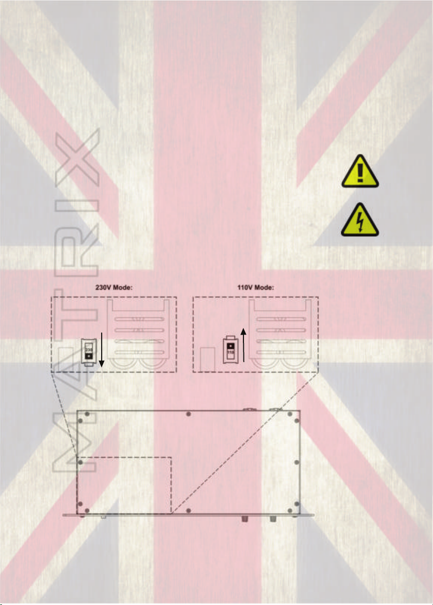
INTERNATIONAL VOLTAGE SELECTION
Your Matrix amplifier should be set at the voltage for your specific country if
selected correctly at the time of ordering. It is possible however to select
alternative region voltages internally via an on-board switch.
This allows for selection of 230v or 110v modes respectively at +/- 15%.
This is approximately 200 to 265v or 95 to 125v.
If you are unsure about undertaking this procedure, please refer to qualified
service personnel.
To access the internal switch, firstly disconnect amplifier from all
equipment & mains supply as lethal voltages are present inside.
Next remove the screws on the lid shown below with a suitable
cross head screwdriver, the lid should now simply lift away without
obstruction, should any resistance be encountered, inspect for
further fasteners holding the lid down.
Within the region indicated below by the dotted area a
internal view similar to that shown below should be visible. With a
finger or ballpoint pen move the switch shown into its alternative
position for secondary voltage mode. Re-assemble amplifier
ensuring all fixings are tight before further use.
NOTE: Ensure correct voltage for region is always selected, otherwise
damage is likely to occur!
14
Page 16

CABLE CHOICE & NEUTRIK® SPEAKON CONNECTORS
Whilst the Matrix GT series amps come with Neutrik® combi inputs and outputs for
maximum flexibility it is important to use good quality cables and connectors. We
recommend using Neutrik® branded connectors wherever possible. We’ve come
across certain low cost 1/4” jacks not connecting properly as well as XLRs not
“locking” which can cause loss or degradation of signal. Whilst many guitarists are
used to using traditional 1/4” jack to jack speaker cables we recommend trying out
Speakon connectors as they offer certain advantages over 1/4” jacks
•No possible confusion with low-current microphone or instrument cables.
•They lock into their sockets with a twisting motion, making them significantly
less prone to disconnection than push in jack plugs.
•They are shielded from human touch, preventing electrical shock from a high-
powered amplifier (especially important given the high wattage of our amps).
•The contacts do not short out during connection or disconnection. This can be a
benefit when working with sound equipment that is in operation.
•The chassis receptacles are airtight, so do not provide an air leak path from
speaker enclosures. (Important in high SPL FRFR cabinets)
•They are usually solderless connections making field maintenance and
construction much easier.
Whilst we appreciate that not everyone will convert their traditional cabs over to
Speakon connectors, you can still use Speakon to 1/4” cables to connect to the GT
series and at least get some benefit!
You can use either NL2FC or NL4FC Speakon connectors with the GT series but only
pins +1 and -1 are used if you use the 4 pole connector type!
If you decide to make your own speaker cables we recommend a twin core cable with
a copper core of at least 2.5mm2 / 12 awg. For cables longer than 6m/20ft a heavier
gauge cable may provide improved performance.
An approximate guide of cable sizing in relation to that of a pencil is shown
below, also note on the right the thin 'bell wire' / budget domestic speaker cable...
never use cable of this gauge to connect to power amplifiers, this can present a fire
risk and will result in poor performance.
15
Page 17

TROUBLESHOOTING:
NOTE:
•Ensure the amplifier has no less than 4 Ohms worth of loading across
each channel for Stereo/Parallel modes.
•Ensure Bridge Mode (if used) is utilised via Output X and is loaded
with no less than 8 Ohms.
•Ensure wiring is safe and correct.
•When heavily driven, the amplifier itself may make a noticeable
hissing sound in relation to the supplied signal. This is a normal
phenomenon relating to the behaviour of certain components which
vibrate slightly under the high powers involved.
•The fans on the GT series may increase their speed when the
amplifier is under load to improve cooling efficiency.
.
(1) THE POWER LIGHT DOES NOT ILLUMINATE
•Check that the mains supply is turned on.
•Check that the mains switch is turned on.
•Check mains lead for damage & check fuse. Replace lead if damaged,
replace fuse if blown.
•Check internal fuse. Replace if blown.
(same type of fuse specified/installed must be used, do not change)
•If fuse re-blows refer to service personnel.
•Check voltage selector of amp is in correct position for required
voltage.
•If fuse has not blown and the voltage selector is in correct position but
the amplifier still malfunctions, refer to service personnel.
(2) OUTPUT VOLUME IS LOW
•Check the signal from the input source and check signal cables. The
amplifiers are designed to operate at an input voltage of 0.775V. If
the intended signal source is below this a lower output volume will
result. Raise the signal level from the source.
(3) NO OUTPUT VOLUME
•Check the amp is receiving a signal from it’s source.
•Check both input and output leads and replace and re-test. In the
case of outputs, if speakons are used make sure they are securely
attached or try a 1/4” cable.
•Check signal output lights are lighting up. These lights are directly
connected to the amplifiers output circuits so if they are lighting up,
the amplifier is outputting a signal and the problem lies elsewhere.
16
Page 18

(4) OUTPUT IS DISTORTED OR THIN SOUNDING
•The protection circuits (current clamps) are operating. Check all leads
for short-circuits. Try another set of leads and loudspeakers.
•Check the amp is not switched to bridged mode and non bridged
output is being used.
•Check leads for correct wiring.
(5) AMPLIFIER IS OVERHEATING (PROTECT LIGHT ON)
•Check that the fan is not obstructed with debris, and is operating and
rotating freely. If the amp is overheating the fans will run in high speed
mode which is audibly louder than normal mode. Switch off amp and
allow to cool. Power on and ensure protect light turns off.
(6) PROTECT LIGHT IS ON
The protect light will illuminate under certain conditions to prevent damage to
the amplifier or connected speakers.
•Check cabinet impedance is not less than 4 ohms per channel or less
then 8 ohms in bridged mode.
•If both channel outputs are connected, check cabinet is in correct
mode (see important notice on page 9) or is compatible.
•Check for short circuits in leads (try a different lead).
•Check for possible short circuit in speaker (try a different speaker).
•Make sure amp has sufficient air flow through fans and vents to avoid
the amp going into thermal protect.
•Power down, disconnect all leads except power and switch on. If
protect light extinguishes then problem was linked to one of the above
items.
•If the protection circuits have detected a DC signal or other damage the
amp will stay in protect mode.
If any of these, or other symptoms persist, please contact your dealer or
alternatively email us at [email protected] for help, advice
and service.
17
Page 19

FULL 2 YEAR WARRANTY:
Summary
Matrix Elements warrants this GT series amplifier for a period of 2 years
from date of purchase to be free of defects in materials and workmanship
under normal conditions and usage. This warranty is transferable but
original proof of purchase date is needed if any claim is to be made on the
warranty. Any products found to be defective within the applicable period
will be repaired or replaced at the discretion of Matrix Amplification
Inc/Ltd. without any charge provided that;
(1) the product was not misused, abused, improperly maintained, or
repaired by any person not authorized by Matrix Amplification Inc/Ltd;
(2) the failure resulted from a defect in material or workmanship and was
not damaged due to use other than its intended use;
(3) the product was not used under abnormal, excessive, or unusual
operating conditions or suffered abuse;
(4) the product is promptly delivered prepaid to the original place of
purchase or to manufacturer together with proof of purchase within the
applicable period.
Limitations and exclusions
We will not warrant items which we deem to have been misused,
damaged due to incorrect connection, neglected or items exhibiting normal
wear and tear. We will not warrant consequential damage to other
products resulting from the incorrect operation or misuse of the item.
Warranty Claims
Contact your dealer (if applicable) in the case of a warranty claim or
alternatively contact us if purchased direct on:
Your statutory rights are not affected
18
Page 20

CARE & MAINTENANCE:
Your Matrix GT series amplifier should give you years of trouble free
service provided you take care of it. Any cleaning should be done with a
damp (not wet) lint free cloth and if needs be, the fans can be cleared
of any dust or debris using either a small brush or compressed air (the
kind suitable for cleaning computer devices). Do not use any abrasive
cleaning products as these may damage the powder coating or printing.
CONTACT US:
Matrix is a company that prides itself on customer feedback and interaction.
We like to hear from our customers with any suggestions they have to help us
continually improve our service. You are very welcome to share your
experience with us by contacting:
Alternatively you can call us.
(+44) (0)845 108 5449 within the UK (calls charged at local rate from
landline) 9.30am - 5pm Mon-Fri (GMT)
or customers within the US can call: (805) 766 8556 9am - 5pm Mon-Fri
(PDT/PST)
We also love sharing our players experience and promoting them where we
can. Any pictures, videos featuring Matrix products or a good old fashioned
thumbs up can be posted on our social media.
https://www.facebook.com/MatrixAmplification
We’re also around to offer any help or advice as best we can if you run into
any problems or have a question, no matter how trivial. We aim to get back
to you within 24 hours (during the week) but bear in mind our main office is
in the UK and there may be a time difference. Again, contact us at:
Thank you from the Matrix Team!
19
Page 21

TECHNICAL SPECIFICATIONS:
GT800GT1000 (1U & 2U)GT1600
Number of Channels:
Watts Per Channel at - 16 Ω:
Watts Per Channel at - 8 Ω:
Watts Per Channel at - 4 Ω:
Watts Bridged (A and B) - 16 Ω:
Watts Bridged (A and B) - 8 Ω:
Supply Voltage:
Internally Selectable Alternative
Voltage:
Average Supply Current, Full Load:
Mains Connector:
Frequency Response:
Signal to Noise Ratio
(ref. Full power 1kHz):
THD (1kHz, full power):
THD (20Hz - 20kHz, full power):
Slew Rate:
Damping Factor (ref. 8R, 100Hz):
Cooling Fan Arrangement:
(Temperature controlled dual speed
fans)
Input Level Sensitivity:
Dimensions (mm):
Weight:
2
125
250
400
400
800
230V +/- 15%
110V +/- 15%
4A (8A at 110v)
10A IEC
8–24,000 Hz
96 dB
0.06%
<0.1%
50 V/µs
>400
2x 40mm
0.775v / 0 dBu
482X44X210
3.7 Kg
2
150
300
500
650
1000
230V +/- 15%
110V +/- 15%
5A (10A @ 110v)
10A IEC
8–24,000 Hz
96 dB
0.06%
<0.1%
50 V/µs
>400
2x 40mm (1U)
1x 80mm (2U)
0.775v / 0 dBu
482X44X210 (1U)
482X88X210 (2U)
4.1 Kg
2
240
480
800
800
1600
230V +/- 15%
110V +/- 15%
8A
10A IEC
8–24,000 Hz
96 dB
0.06%
<0.1%
50 V/µs
>400
1x 80mm
0.775v / 0 dBu
482X88X210
4.7 Kg
20
Page 22

CE Declaration:
Issuers Name and Address:
Andrew Hunt MATRIX AMPLIFICATION LIMITED/MATRIX AMPLIFICATION
INC, 32 Dewsland Park Road, Newport, South Wales. United Kingdom.
NP20 4EF
Products:
GT800FX, GT1000FX 1u, GT1000FX 2u, GT1600FX
Equipment Type:
Commercial Audio Amplifiers
Safety Standard:
AMD1: 2005 and IEC 60065: 2001 7th Ed. EMC Standards: EN 61000-4-2:2001 EN 61000-
4-3:2006 EN 61000-4-4:2007 EN 61000-4-5:2006 EN 61000-4-6:2006 EN 61000-4-
11:2001 EN 55103-1:1997 EN 55103-1:1997 EN 55103-2:1997 EN 61000-3-3:2008 EN
61000-3-2:2005 and AMD1: 2008 EN 55022:2006
Safety Requirements - Audio Video and Similar Electronic Apparatus. Electrostatic Discharge
Immunity (Environment E2-Criteria B, 4k V Contact, 8k V Air Discharge). Radiated, Radio-
Frequency, Electromagnetic Immunity (Environment E2, criteria A). Electrical Fast Transient/Burst
Immunity (Criteria B). Surge Immunity (Criteria B). Immunity to Conducted Disturbances
Induced by Radio-Frequency Fields (Criteria A). Voltage Dips, Short Interruptions and Voltage
Variation. Electromagnetic Compatibility - Product Family Standard for Audio, Video, Audio-Visual
and Entertainment Lighting Control Apparatus for Professional Use, Part 1: Emissions. Magnetic
Field Emissions-Annex A @ 10 cm and 20 cm. Electromagnetic Compatibility - Product Family
Standard for Audio, Video, Audio-Visual and Entertainment Lighting Control Apparatus for
Professional Use, Part 2: Immunity. Limits for Harmonic Current Emissions (equipment input
current less than or equal to 16 A per phase). Limits and Methods of Measurement of Radio
Disturbance Characteristics of ITE: Radiated, Class B Limits; Conducted, Class A. Limitation of
Voltage Fluctuations and Flicker in Low-Voltage Supply Systems Rated Current less than or equal
to 16A. I certify that the product identified above conforms to the requirements of the EMC
Council Directive 89/336/EEC as amended by 92/31/EEC, and the Low Voltage Directive
73/23/EES as amended by 93/68/EEC.
Signature:
Andrew Hunt, Managing Director.Date of Issue: 04/02/2014
21
Page 23

NOTES:
22
Page 24

Monmouth, Wales, NP25 5JA.
93003, United States of America.
amplifiers
heavyweight tone
without the heavy weight
www.matrixamplification.com
Matrix Amplification inc. 1376 Walter Street, Unit 3, Ventura, California,
Matrix Amplification, Unit 1b, Techways, Wonastow Road Industrial Estate,
GT-Series
 Loading...