

Matrix Elements GT800fX, GT1000fX, GT1600fX User Manual
guitar amplification
made in britain, heard worldwide
MATRIX
MATRIX
POWER
on
POWER
on
POWER
on
POWER
on
BRIDGE
BRIDGE
BRIDGE
BRIDGE
MONO
MONO
MONO
MONO
AB
CHANNEL LEVELS
AB
CHANNEL LEVELS
AB
CHANNEL LEVELS
AB
CHANNEL LEVELS
ON
PROTECT
ON
PROTECT
ON
PROTECT
ON
PROTECT
SIGNALSIGNAL
SIGNALSIGNAL
SIGNALSIGNAL
SIGNALSIGNAL
GT 800FX
POWER AMPLIFIER
GT1000FX
POWER AMPLIFIER
GT1000FX
GT1600FX
gt series amplifiers
user manual
models covered:
gt800fx, gt1000fx (1u & 2u),
gt1600fx
WWW.MATRIXAMPLIFICATION.COM

CONTENTS:
1. Thank You & Unpacking.
PAGE:
1
Thank You
Congratulations on the purchase of your new
Matrix Professional Power Amplifier.
Matrix amplifiers are the result of many
decades of experience in the design of
exceptionally robust and reliable amplifiers.
They are designed to breathe life into your
sound, by controlling your speakers with
exacting authority through the uncompromising
delivery of clean, undistorted power, from a
package which is smaller and lighter than you
might expect for the performance it delivers.
This manual will help you to get the most from
your amplifier. For maximum benefit, it is
recommended that all instructions and
warnings are carefully read. Also be sure to
read the notices regarding correct wiring of
output connectors as this impacts the operation
of the amplifier.
For warranty service, please retain your receipt
and all packaging that comes with the
amplifier, as it has been specifically designed to
transport the amplifier safely.
Unpacking
Please unpack and inspect your new amplifier
for any damage that may have occurred during
transit. If damage is found, notify the carrier
immediately.
Note: A suitable mains lead is provided and can
be found packaged with the amplifier.
PLEASE RETAIN ALL FACTORY
PACKAGING FOR ANY FUTURE POSTAL
TRANSIT.
2. Safety Notices & FCC
Declaration.
3. Layout:
3.1 Front Panel.
3.2 Rear Panel.
4. Before You Start.
5. Getting Started, Powering
Up & Connections.
6. Set-Up Examples.
7. International Voltage
Selection.
8. Choosing Cables.
9. Troubleshooting.
10. Warranty.
11. Care & Contact Us.
12. Technical Specs.
13. CE Declaration.
14. Notes.
2
3-7
3-4
5-7
7
8-9
10-13
14
15
16-17
18
19
20
21
22
1
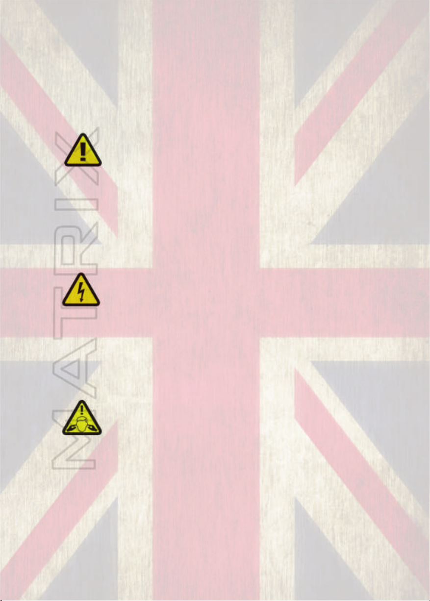
CAUTION:
OBSERVE ALL SAFETY AND
USAGE INSTRUCTIONS TO AVOID
POSSIBLE DAMAGE TO
EQUIPMENT AND EXPOSURE TO
HAZARDS. THIS SYMBOL
UNIVERSALLY FLAGS CAUTION
NOTICES
LETHAL VOLTAGES PRESENT AT
SPEAKER, CABLE AND AMPLIFIER
TERMINALS; ENSURE ALL
WIRING IS SAFE AND CORRECT
BEFORE USE. THIS SYMBOL
ALSO UNIVERSALLY FLAGS
ELECTRICAL HAZARDS
DO NOT OPEN UNIT; LEAVE ALL
INTERNAL SERVICE OPERATIONS
TO A QUALIFIED TECHNICIAN.
THIS PRODUCT IS CAPABLE OF
PRODUCING SOUND PRESSURE
LEVELS WHICH MAY DAMAGE
HEARING.
THE USER IS RESPONSIBLE FOR
EXPOSURE LEVELS AND USE OF
HEARING PROTECTION.
OPERATING ENVIRONMENT:
The amplifier is designed for use in environments which
protect it from rain, unusually high air humidity and
temperature.
Place on a surface where it cannot be easily dislodged,
potentially causing damage to the unit or injury to a person.
Ensure that the location will not expose the amplifier to
spillage of liquids/drinks, sprays/vapours or high humidity.
Ensure the amplifier is installed in a place which is not
subject to abnormally high temperatures and maintain
sufficient ventilation to prevent overheating.
For temporary use outside, apply similar caution however,
careful to ensure placement accounts for changing weather
conditions and that extreme wind/rain/heat will not find its
way to the equipment.
When taking any equipment from a cold environment
(unheated storage, vehicles, etc), into a warm one, allow the
equipment time to become acclimatised to the ambient
temperature, as condensation is likely to form in the
amplifier, potentially causing it to malfunction if put into
service too soon.
Note: This equipment has been tested and found to comply
with the limits for a Class B digital device, pursuant to part
15 of the FCC Rules. These limits are designed to provide
reasonable protection against harmful interference in a
residential installation. This equipment generates, uses and
can radiate radio frequency energy and, if not installed and
used in accordance with the instructions, may cause harmful
interference to radio communications. However, there is no
guarantee that interference will not occur in a particular
installation. If this equipment does cause harmful
interference to radio or television reception, which can be
determined by turning the equipment off and on, the user is
encouraged to try to correct the interference by one or more
of the following measures:
— Reorient or relocate the receiving antenna.
— Increase the separation between the equipment and
receiver.
— Connect the equipment into an outlet on a circuit different
from that to which the receiver is connected.
— Consult the dealer or an experienced radio/TV technician
for help.
2
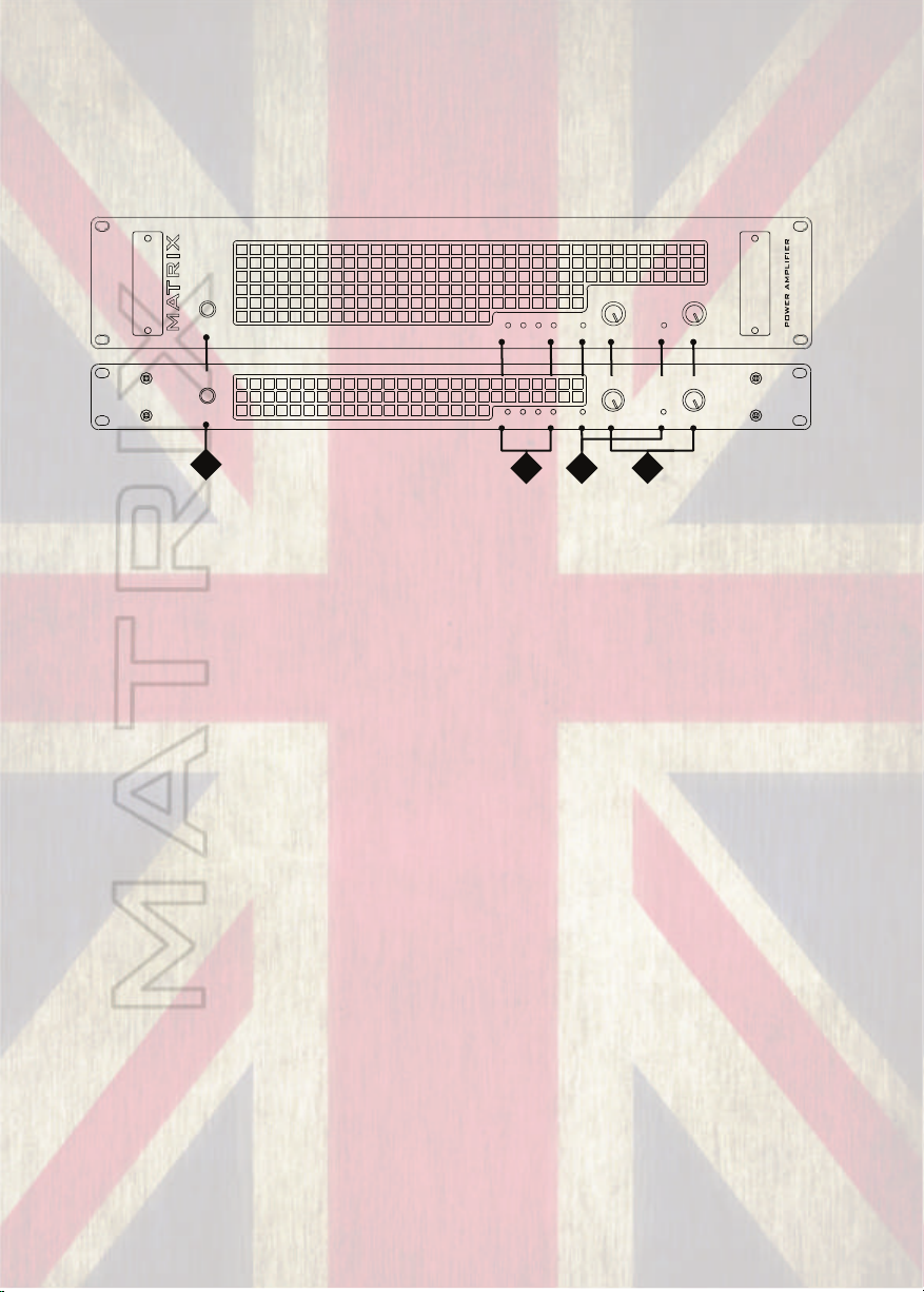
FRONT AND REAR PANEL LAYOUTS: 1U & 2U MODELS
The front and rear panels on 1U & 2U versions of the amps share the same
features and layouts.
1U MODEL (GT800 & GT1000) & 2U MODEL (GT1000 & GT1600)
POWER
on
MATRIX
POWER
on
1
(1) Power Switch
MONO
MONO
AB
AB
4
ON
BRIDGE
PROTECT
ON
BRIDGE
PROTECT
2
SIGNALSIGNAL
CHANNEL LEVELS
SIGNALSIGNAL
CHANNEL LEVELS
3
GT x x x FX
GT x x x F X
POWER AMPLIFIER
This switch controls the power supply to the amplifier.
(2) Indicator Section, Status:
a. Power Indicator
This indicator shows when the amplifier is on and is receiving power.
b. Parallel Mono Mode Indicator
This indicator shows if (parallel) MONO mode is selected on the rear panel.
For channel pair A and B only Input A will be used to drive both channels. Full
independent level control of the amplifier output stages is still possible via the Gain
controls.
c. Bridged Mono Mode Indicator
This indicator shows if Bridged mode is selected on the rear panel. It is most
important that this indicator is not illuminated unless bridged mode is required. This
is because when bridged mode is selected, Channel A will be out of phase with
Channel B. This will result in poor bass response and an unsatisfactory sound if left
and right outputs are used. In this mode Channel A controls the output level.
d. Protect Indicator
This indicator lights briefly during the power up cycle and also lights should a
fault occur. Illumination of the protect indicator, shows that the output of the
amplifier has been disconnected by means of an internal relay to protect connected
speaker systems from being damaged by the fault.
3
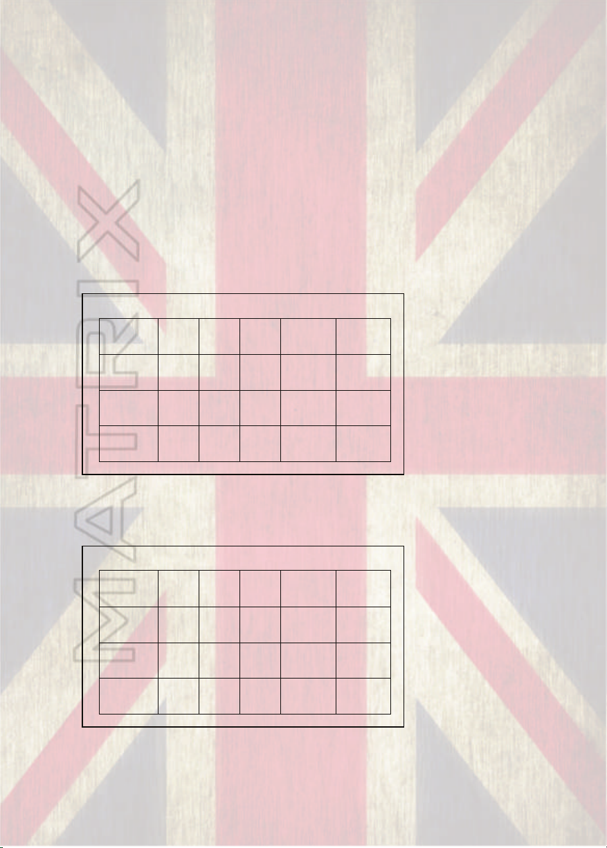
(3) Gain Controls
4
Ohms
8
Ohms
16
Ohms
8 Ohms
(Bridged)
16 Ohms
(Bridged)
GT800FX
50
30
15
100
60
GT1000FX
60
40
20
120
80
GT1600FX
100
60
30
200
120
4
Ohms
8
Ohms
16
Ohms
8 Ohms
(Bridged)
16 Ohms
(Bridged)
GT800FX
100
60
30
200
120
GT1000FX
120
80
40
240
160
GT1600FX
200
120
60
400
240
The level of each Channel is individually adjusted by these controls.
Rotating these controls fully clockwise, results in no attenuation to the incoming audio
signals.
(4) Indicator Section, Signal levels:
These show the (Peak) output level of the amplifier for each channel, in both
Stereo and Mono modes. These will start to illuminate when a signal is present at the
speaker sockets when driven above a threshold of approximately -9db. Note that for
levels below this amount the led may not illuminate. The signal level lights are useful in
indicating how much power is being sent to the speaker connected. The -9db threshold
relates to approximately 12.5% of the amps available power at the load it is connected
to. The table below gives the ratings at -9db for typical impedances connected.
Signal lights starting to blink at -9db
For every increase of 3db that occurs, a doubling of the power is needed, so to that
effect, when the signal lights start to stay permanently on at -6db the power the amp
produces is doubled. Most stage volumes will occur somewhere between the two
Signal lights starting to stay on at -6db
but if you’re happy with the volume levels and the signal lights are not lighting up,
that’s fine!
4

1U MODEL (GT800 & GT1000) & 2U MODEL (GT1000 & GT1600)
WWW.MATRIXGUITARAMPLIFICATION.COM
_
+
For A+B Bridged Output Use Socket Marked X
For Bridged Output Only !
NL2
NL2
1/4”
1/4”
1:X
1:A
X
DESIGNED BY ANDREW HUNT AND MANUFACTURED IN THE UK BY MATRIX
1:A
X
DESIGNED BY ANDREW HUNT AND MANUFACTURED IN THE UK BY MATRIX
6
NL2
1/4”
1/4” & SPKN. OUT
1/4” & SPKN. OUT
+
_
AC Power Supply Requirement
50 to
230V 6A
110V 12A
60Hz
DO NOT REMOVE COVERS
LETHAL VOLTAGES INSIDE.
THIS EQUIPMENT MUST BE
EARTHED.
DO NOT USE IN
DAMP CONDITIONS.
AC Power Supply Requirement
50 to
230V 6A
110V 12A
60Hz
DO NOT REMOVE COVERS
LETHAL VOLTAGES INSIDE.
THIS EQUIPMENT MUST BE
EARTHED. DO NOT USE IN
DAMP CONDITIONS.
WWW.MATRIXGUITARAMPLIFICATION.COM
+0 dBu/0.775V
+0 dBu/0.7V
8
+
Both Input and Output Connectors
Accept 1/4” Jackplugs in Addition to XLR/NL2
1/4” & XLR IN
+
1/4” & XLR IN
7
For Bridged Output Use Socket Marked X - For Bridged Output Only !
5
(5) Cooling Fan Outlets
Hot air exits here. Make sure all rear (and front) ventilation paths are
free from obstruction and air flows freely, otherwise the amplifier will
trip into thermal protect mode prematurely and in some extreme
circumstances damage may occur.
(6) Output Connectors
The Output sockets are Neutrik® Speakon / 1/4” combi connectors.
They accept both Neutrik® NL2FC & 1/4” jack plugs (NL4FC
accepted, however only terminal pair 1 carry signals). Avoid inferior
alternatives, as they may present numerous hazards due to less than
ideal construction.
9
When inserting speakon plugs turn clockwise until you hear it
click; This ensures correct connection has been made. To remove, pull
back the levered tab and turn anti-clockwise.
Ready-made, sensibly priced, quality interconnection leads
suitable for use with the amplifier should be easy to source. However,
with sufficient skill, it is possible to make/modify leads for the task.
•Only the first two pins (+1 and -1) are used in this amplifier.
•When utilising the 1/4” output option the centre pin (Tip) is
connected to +1 & the outer sheath (Sleeve) is connected to
-1.
•For STEREO/MONO operation, unmodified “off the shelf”
cables will usually work fine.
•For BRIDGED MONO mode, Output is exclusively available
from OUTPUT X, do not use at any other time.
5

CAUTION: Whilst we recommend that Neutrik speakon connections
are always used for the safest way of connecting to the amplifier, the
option is also provided to use 1/4” jack connections with these
outputs. Take extra care when connecting leads to ensure that these
are not accidentally connected to the inputs and outputs of other
equipment not designed specifically to do so, otherwise damage to
equipment is likely to occur.
Take extra care with 1/4” jack speaker connections, the exposed plug end
can present an electric shock hazard, also never allow the outputs to be
shorted, equipment damage may occur. Finally, never use standard 1/4”
instrument leads for connection between amplifier and loudspeaker, choose a
quality speaker lead for this specific task for safe operation. and optimal
performance.
(7) Input Signal Sockets.
These are Neutrik® combined female XLR and 1/4" jack sockets.
For cable runs of under 12”, (ie. within a rack system) standard good quality
instrument leads should provide a similar level of RF shielding to XLR cables.
For longer cables runs, balanced cables (XLRs) are recommended.
(8) Output Mode Selector.
STEREO, MONO or BRIDGED (mono) Output can be selected using this
switch.
Take care to ensure the correct mode for your application is selected.
•In Stereo mode, channels A and B operate independently, when fed
with separate input signals. (Think of this as two separate mono amps
fed by their own input.)
•In Parallel (Mono) mode, Input A is connected to feed both amplifier
channel A and B. Input B is not used. Full independent level control
over each amplifier output channel remains possible. (This is useful if
you want to send the same mono signal to two separate cabs).
•In Bridged (Mono) mode, the input from channel A is fed out of phase
to channel B and combined to give a higher power mono output.
Note: Bridged Output X is used exclusively for this mode, do not
use at any other time. Using output channel A or B whilst
Bridged mode is selected will give a thin, out of phase sound,
lacking bass through those outputs.
6
(9) Power Connection
Mains power is supplied to the amplifier by a standard 10 Amp IEC
mains socket.
An appropriate mains lead is supplied with the amplifier.
Note: The amplifier requires a stable power supply to function
as intended. Ensure that the power source (mains power
supply, generator, etc.) is suitable for this application and
adequate power is available. Poorly selected power sources
result in sub-optimal performance, increased likelihood of
tripping breakers, blowing fuses and in extreme situations
damage to equipment may occur.
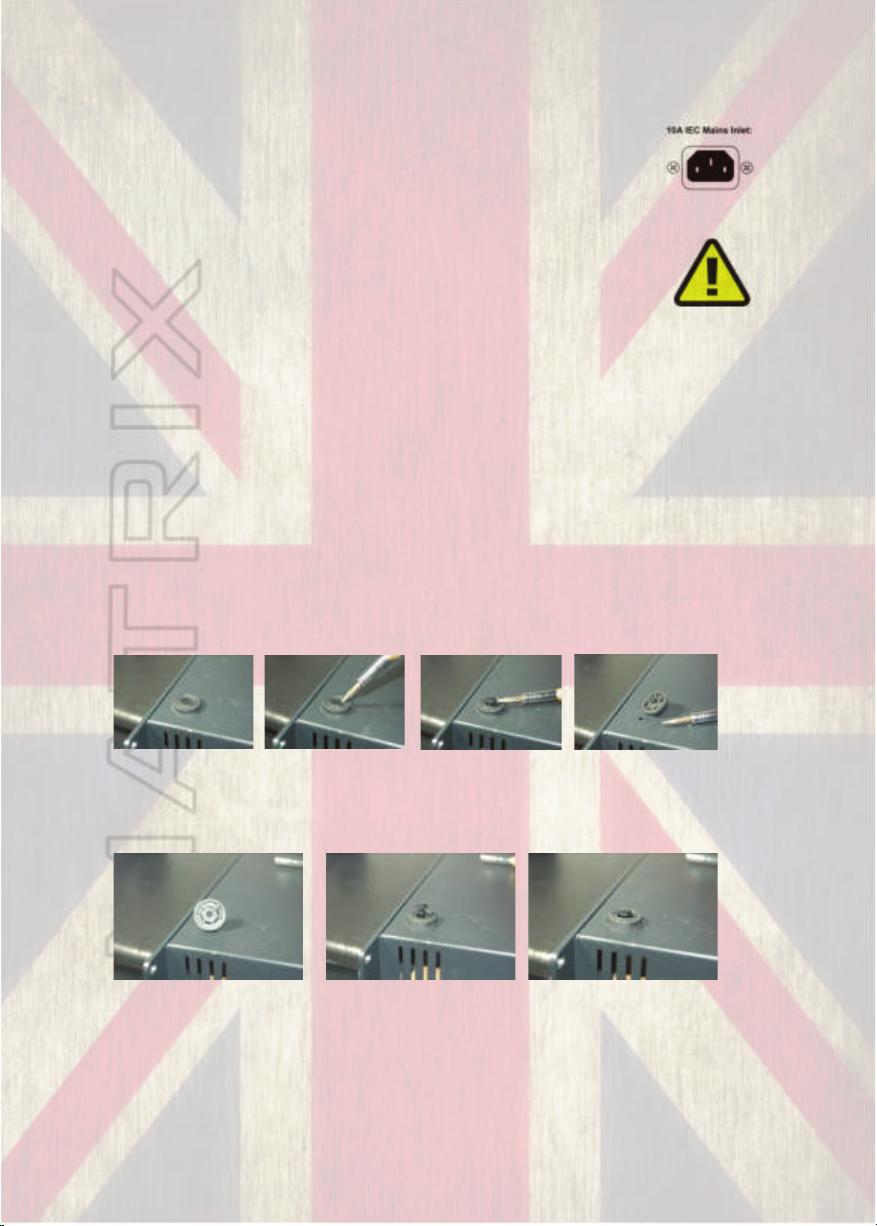
BEFORE YOU START:
If you intend to rack mount your GT series amplifier you may want to
consider removing the rubber feet from the amplifier to allow maximum
room for other units that may share the rack space. This is a simple
process. Using a small flat bladed screwdriver gently prise the shiny plastic
insert up from the chassis which will enable the feet to be removed. Store
somewhere safe!!
1234
To replace the feet simply pull the plastic insert so the mechanism is closed,
line up the foot with the chassis hole and push into place.
123
7
 Loading...