

Page 1
guitar amplification
WWW.MATRIXAMPLIFICATION.COM
proudly made in the usa
fr10/12 neolight
full range speakers
user manual
models covered:
fr10, fr12
Page 2

PAGE:
1
2
3-7
3-4
5-7
7
8-9
10-13
14
15
16-17
18
19
20
21
22
1
Thank You
Congratulations on the purchase of your new
Matrix Elements Full Range speaker.
Matrix amplifiers and speakers are the result of
many decades of experience in the design of
exceptionally robust and reliable pro audio
equipment. They are designed to breathe life
into your sound, by controlling your speakers
with exacting authority through the
uncompromising delivery of clean, undistorted
power, from a package which is smaller and
lighter than you might expect for the
performance it delivers.
This manual will help you to get the most from
your full range speaker For maximum benefit, it
is recommended that all instructions and
warnings are carefully read.
For warranty service, please retain your receipt
and all packaging that comes with the
amplifier, as it has been specifically designed to
transport the amplifier safely.
Unpacking
Please unpack and inspect your new speaker
for any damage that may have occurred during
transit. If damage is found, notify the carrier
immediately.
Note: A suitable mains lead is provided and can
be found packaged with the amplifier.
PLEASE RETAIN ALL FACTORY
PACKAGING FOR ANY FUTURE POSTAL
TRANSIT.
CONTENTS:
1. Thank You & Unpacking.
2. Safety Notices & FCC
Declaration.
3. Layout:
3.1 Front Panel.
3.2 Rear Panel.
4. Before You Start.
5. Getting Started, Powering
Up & Connections.
6. Set-Up Examples.
7. International Voltage
Selection.
8. Choosing Cables.
9. Troubleshooting.
10. Warranty.
11. Care & Contact Us.
12. Technical Specs.
13. CE Declaration.
14. Notes.
Page 3
CAUTION:
OBSERVE ALL SAFETY AND
USAGE INSTRUCTIONS TO AVOID
POSSIBLE DAMAGE TO
EQUIPMENT AND EXPOSURE TO
HAZARDS. THIS SYMBOL
UNIVERSALLY FLAGS CAUTION
NOTICES
LETHAL VOLTAGES PRESENT AT
SPEAKER, CABLE AND AMPLIFIER
TERMINALS; ENSURE ALL
WIRING IS SAFE AND CORRECT
BEFORE USE. THIS SYMBOL
ALSO UNIVERSALLY FLAGS
ELECTRICAL HAZARDS
DO NOT OPEN UNIT; LEAVE ALL
INTERNAL SERVICE OPERATIONS
TO A QUALIFIED TECHNICIAN.
THIS PRODUCT IS CAPABLE OF
PRODUCING SOUND PRESSURE
LEVELS WHICH MAY DAMAGE
HEARING.
THE USER IS RESPONSIBLE FOR
EXPOSURE LEVELS AND USE OF
HEARING PROTECTION.
OPERATING ENVIRONMENT:
This amplified speaker is designed for use in environments
which protect it from rain, unusually high air humidity and
temperature.
Place on a surface where it cannot be easily dislodged,
potentially causing damage to the unit or injury to a person.
Ensure that the location will not expose the amplifier to
spillage of liquids/drinks, sprays/vapours or high humidity.
Ensure the amplifier is installed in a place which is not
subject to abnormally high temperatures and maintain
sufficient ventilation to prevent overheating.
For temporary use outside, apply similar caution however,
careful to ensure placement accounts for changing weather
conditions and that extreme wind/rain/heat will not find its
way to the equipment.
When taking any equipment from a cold environment
(unheated storage, vehicles, etc), into a warm one, allow the
equipment time to become acclimatised to the ambient
temperature, as condensation is likely to form in the
amplifier, potentially causing it to malfunction if put into
service too soon.
Note: This equipment has been tested and found to comply
with the limits for a Class B digital device, pursuant to part
15 of the FCC Rules. These limits are designed to provide
reasonable protection against harmful interference in a
residential installation. This equipment generates, uses and
can radiate radio frequency energy and, if not installed and
used in accordance with the instructions, may cause harmful
interference to radio communications. However, there is no
guarantee that interference will not occur in a particular
installation. If this equipment does cause harmful
interference to radio or television reception, which can be
determined by turning the equipment off and on, the user is
encouraged to try to correct the interference by one or more
of the following measures:
— Reorient or relocate the receiving antenna.
— Increase the separation between the equipment and
receiver.
— Connect the equipment into an outlet on a circuit different
from that to which the receiver is connected.
— Consult the dealer or an experienced radio/TV technician
for help.
2
Page 4
3
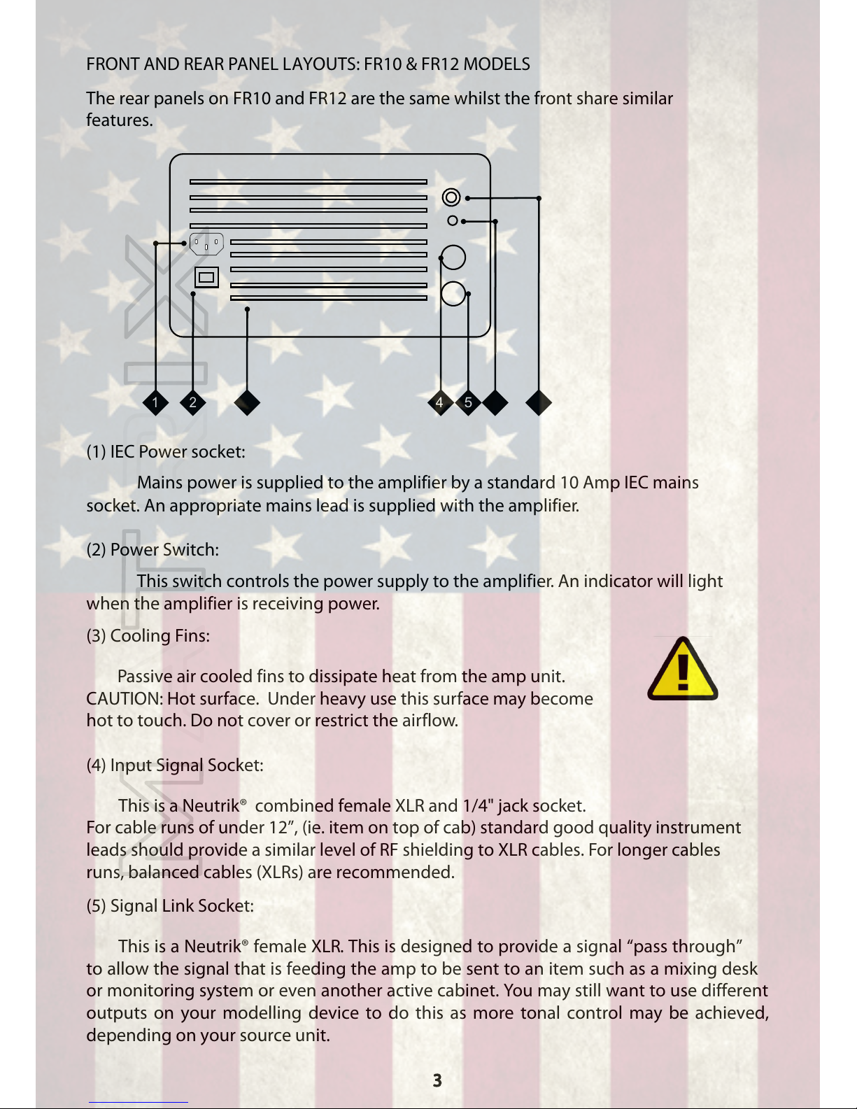
FRONT AND REAR PANEL LAYOUTS: FR10 & FR12 MODELS
The rear panels on FR10 and FR12 are the same whilst the front share similar
features.
(1) IEC Power socket:
Mains power is supplied to the amplifier by a standard 10 Amp IEC mains
socket. An appropriate mains lead is supplied with the amplifier.
(2) Power Switch:
This switch controls the power supply to the amplifier. An indicator will light
when the amplifier is receiving power.
(3) Cooling Fins:
Passive air cooled fins to dissipate heat from the amp unit.
CAUTION: Hot surface. Under heavy use this surface may become
hot to touch. Do not cover or restrict the airflow.
(4) Input Signal Socket:
This is a Neutrik® combined female XLR and 1/4" jack socket.
For cable runs of under 12”, (ie. item on top of cab) standard good quality instrument
leads should provide a similar level of RF shielding to XLR cables. For longer cables
runs, balanced cables (XLRs) are recommended.
(5) Signal Link Socket:
This is a Neutrik® female XLR. This is designed to provide a signal “pass through”
to allow the signal that is feeding the amp to be sent to an item such as a mixing desk
or monitoring system or even another active cabinet. You may still want to use different
outputs on your modelling device to do this as more tonal control may be achieved,
depending on your source unit.
5
4
2
3
6
7
1
Page 5
(6) DSP Function Indicator
This light will operate briefly when the DSP select button is pressed, to provide an
indication of which fuction the DSP (Digital Signal Processing) is providing within the
amp module and will then turn solid. Bear in mind that throughout all functions the
active crossover integrity is still held.
NB: We’ve also added an audible guide consisting of a “beep” when the unit is
powered on.
Light flashes once/ 1 beep: This is the default setting with no effect on the DSP
function. Flat/neutral mode.
Light flashes twice/2 beeps: This setting approximates an Equal Loudness Curve (also
known as Fletcher Munson Effect). This will boost both the highs and lows which is
desireable when using the speaker at lower volumes (such as home or bedroom levels)
to avoid altering your patches for home use. It is approximate for around 75db so some
alteration of patches (or EQ) may be needed at higher or lower volumes.
Light flashes three times/3 beeps: This is the low shelf setting which sets a shelving
EQ at 100hz. This may be used in situations to correct ground coupling or boomy
hollow stages to correct the extra low end these situations may give.
NB: The module will reset to “flat”mode when powered off.
NB: Once the DSP mode has been selected, the light will come on after 5 seconds
and remain constantly lit to serve as a power indicator. In this state it also functions
as a clip/limit light which will flash around 10 times a second if the amp limit is
reached.
(7) Volume Control:
This controls the overall volume of the amp module. The input sensitivity is set for
0db so if the volume of the amp is insufficient when full, try increasing the signal that
is fed to the amps input to increase the overall volume. The amp is rated at
300w which should be more than sufficient for stage use (where levels tend
to vary from 60-100w).
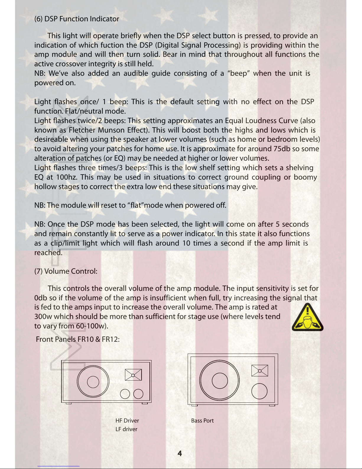
Front Panels FR10 & FR12:
LF driver
Bass Port
HF Driver
4
*1
*1
*2
*2
*3*3
*1
*2
*3
Page 6

GETTING STARTED, POWERING UP & CONNECTIONS:
Your FR Series speaker comes equipped with a power lead specific for the
requirements of your country. Use only the correct lead with the correct rated
fuse for your country’s power requirements. Use of an incorrect lead or fuse
rating could lead to damage of the amplifier and speaker.
5
1.Connect the supplied mains power lead to the IEC inlet on the rear of the
speaker.
2. Connect the signal source (modelling device with cabinet simulations
engaged) to the input on the amp module. Use a good quality instrument
cable or balanced XLR lead. This will depend on the output connections of
your source unit.
3. Making sure that the amp is turned off at this point, power up your signal
source (this prevents any unwated signal noise transmitted to the speaker.
Now with the volume on the amp all the way down, power on the amplifier
via the power switch located on the module. You may hear a slight “thump”
as the unit is powered on. This is perfectly normal.
5. Adjust the controls of the input source to a required level (ideally 0db or
.775v) and steadily increase the FRs volume until a sufficient level is
achieved. Adjust the levels of the relevant volume controls until desired
volume is achieved.
NOTE: The FR10&12s volume control is basically anattenuator. That
means that to achieve full power at their specified load they requires a
signal of .775v (0db) and the volume knobs up full. If you put a higher
level signal into the amp, it will achieve it's full power rating earlier
than at full volume position and inversely, if you put a lower level
signal in, say -6db, the amps full volume will always be -6db of full
power rating.
If your volume is lower than expected even with the amp module on full
then look to increse the signal level going into the amp. This could be the
individual patch volume or the master volume of the unit or indeed the
send level of a preamp. Be aware of the noise floor of a unit as well.
Turning something up full will usually turn up the amount of noise the unit
generates. The FR10&12s amp modules are obviously designed to be
turned up full and have a low level of noise/distortion but you may
experience issues if you turn up the signal being fed into the Matrix too
much and have the volume of the amp set too low. If the output is too
great, the clip light (DSP Function light) will flash whilst the signal is
active and some signal distortion may result. Lower either main volume or
input signal to correct.
Page 7
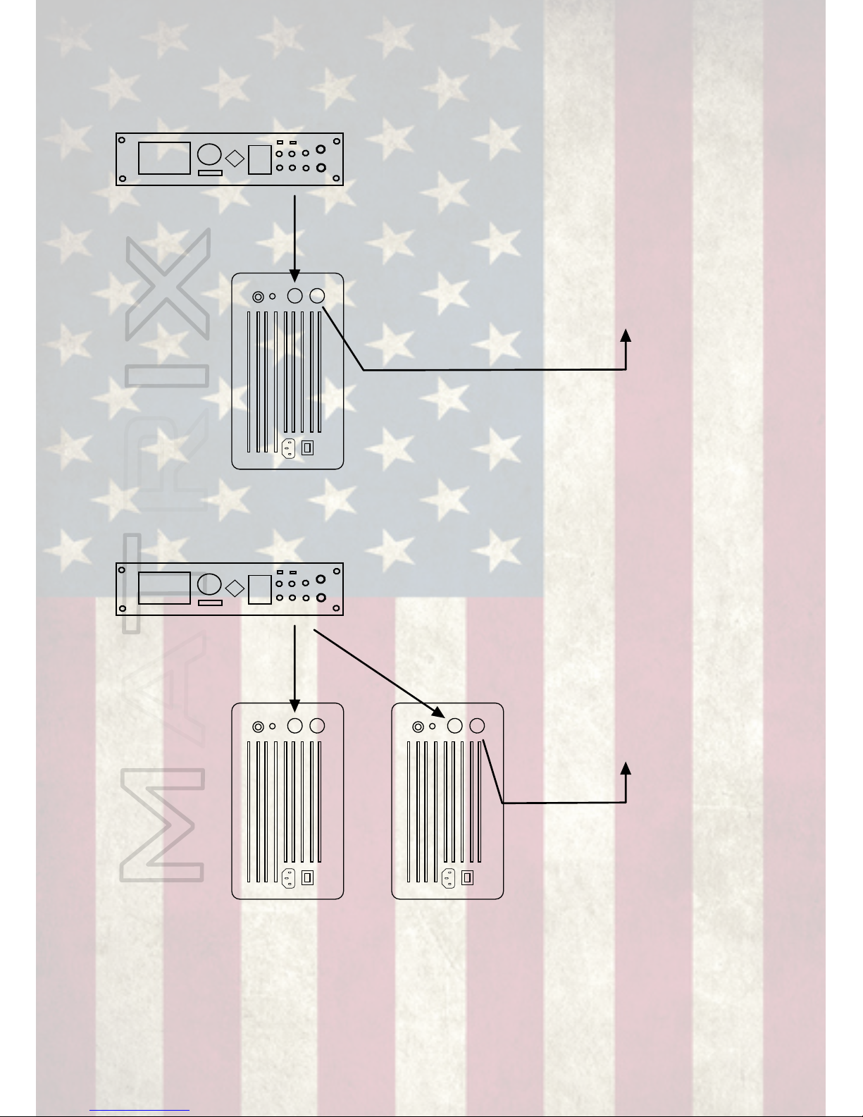
6
Link output from FR amp module
can be used to send signal on to
mixing desk, In ear monitors etc. In
the case of sending to another
powered speaker this would give
two FR cabs running a mono signal
which may be preferrable in larger
venues
*
Main Stereo Outs to
Inputs on FR Amp
Modules
The link out from one or both
FR cabs can be used to send
the signal to another device
such as mixing desk or in ear
monitors. NB: If your
modeller has multiple outputs
though you may find you get
more control over tonality and
level from using those.
SOME TYPICAL SET-UP EXAMPLES:
Modelling System To One* FR Cab Mono
Main Mono/L Out to
Input on FR Amp
Module
Modelling System To Two FR Cabs Stereo
Page 8
7
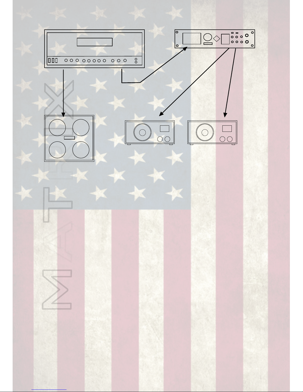
Wet/Dry/Wet Rig Hybrid FR/Traditional
Main Speaker Out from Amp to
Dry Cab (no effects)
FX Send or Line Out from Amp to
Input of Effects Unit
Stereo L&R Out
from FX to Inputs
on FR Amp
Modules. NB:
Make sure cab
sims are enabled!
NOTE: The above system can give a “best of both worlds” set-up utilising
the flexibility of cabinet simulations through the attached FR cabs and the
feel and response on a traditional rig with the center “dry” cab. You can
even use a lightweight Neolight series cab from “yours truly” to provide a
portable and lightweight solution. The unit “feeding” the FR cabs is
providing effects and cabinat emulation. A standard “FX” only unit would
not be suitable for this setup.
Page 9
8
INTERNATIONAL VOLTAGE SELECTION
Your Matrix amplifier should be set at the voltage for your specific country if
selected correctly at the time of ordering. It is possible however to select
alternative region voltages internally via an on-board switch.
This allows for selection of 230v or 110v modes respectively at +/- 15%.
This is approximately 200 to 265v or 95 to 125v.
If you are unsure about undertaking this procedure, please refer to qualified
service personnel.
Access to the internal switch requires some diassembly and again,
if you are unsure, please refer to qualified service personnel. Firstly
disconnect amplifier from all equipment & mains supply as lethal
voltages are present inside. Next remove the screws that mount the
module to the cab with a suitable cross head screwdriver. All
screws except the top and bottom center ones should be removed.
The module should now lift away from the cabinet but will still be
attached to the speakers internally. The speaker wires must be
unclipped from the terminal spades to allow full removal. Make a
note of which colour goes where. Once removed the top and center
screws can be undone to allow the rear of the module to be
unattached. This allows access to the circuit board which contains
the switch to change voltage. It is located next to an orange relay
and clearly marked 230V and 110V.
With a finger or ballpoint pen move the switch shown into its
desired position for your mains power voltage. Re-assemble
amplifier ensuring all fixings are tight before further use.
NOTE: Ensure correct voltage for region is always selected, otherwise
damage is likely to occur!
CABLE CHOICE & NEUTRIK® CONNECTORS
Whilst the Matrix FR10&12 cabs come with Neutrik® combi inputs for maximum
flexibility it is important to use good quality cables and connectors. We recommend
using Neutrik® branded connectors wherever possible. We’ve come across certain
low cost 1/4” jacks not connecting properly as well as XLRs not “locking” which
can cause loss or degradation of signal.
For the “link” output on the cabs we have only provided a standard XLR socket.
This is to provide the best possible signal passage with the least interferance,
especially seeing as the distances involved may be further which increase the
chance of RF interferance.
Page 10
9
TROUBLESHOOTING:
(1) THE POWER LIGHT DOES NOT ILLUMINATE
•Check that the mains supply is turned on.
•Check that the mains switch is turned on.
•Check mains lead for damage & check fuse. Replace lead if damaged,
replace fuse if blown.
•Check internal fuse. Replace if blown.
(same type of fuse specified/installed must be used, do not change)
•If fuse re-blows refer to service personnel.
•Check voltage selector of amp is in correct position for required
voltage.
•If fuse has not blown and the voltage selector is in correct position but
the amplifier still malfunctions, refer to service personnel.
(2) NO OUTPUT VOLUME
•Check the signal from the input source. We’ve all done it. Forgot to
turn the volume up on the signal source....haven’t we? If the volume
is up, make sure settings in I/O menus are ok.
•Check signal cables. Whilst this may sound obvious, it is perhaps the
most common reason for malfunctions. Wear and tear on cables does
take it’s toll and when the “tangle fairies” have invaded your gig bag,
it’s easy for breaks to occur. Have a spare and invest in a cable tester
or multi-meter.
(3) LOW OUTPUT VOLUME
•Check the signal from the input source. The amplifiers are designed to
operate at an input voltage of 0.775V. If the intended signal source is
below this a lower output volume will result. Raise the signal level
from the source.
•On bigger stages if volume is still unsufficient, move the speaker to a
better position. Closer or to the side (side-fill) may improve it. Angling
the speaker may also help using some small tilting speaker stands.
For all but the biggest stages though, the FR cabs should be able to
handle it.
(4) OUTPUT IS DISTORTED OR THIN SOUNDING
•Check input source for clipping. Reduce source volume if necessary
and increase amp module volume.
•Check leads for correct wiring.
•If a driver issue is suspected, refer to Matrix support personnel.
Page 11
10
(5) OUTPUT IS TOO BASSY OR TOO THIN
•Check the correct DSP setting is selected as at higher volumes the
effects can be enhanced.
•Check that patches have been “tweaked” at gig or rehearsal volumes.
This could be a result of the “Fletcher-Munson Effect” or equal
loudness curve to give it it’s new name. This basically means that at
higher volumes, you’ll need to reduce the high and low frequencies to
avoid sounding “scooped”.
•Check cab sims are enabled in your patch. If not you’ll get a very thin
buzzy sound, the “bee in a biscuit tin” syndrome of the full amp signal
being reproduced by a full range speaker.
For many other problems a simple troubleshooting process can help before
contacting Matrix Support. Double check all leads and try new ones that
you know work. If a driver problem is suspected, try some full range music
through the input as this will often point out more dramatically where a
problem lies.
If any of these, or other symptoms persist, please contact your dealer or
and service. We’re here to help and we aim to get back to people within 24
hours.
CARE & MAINTENANCE:
Your Matrix FR series active cab should give you years of trouble free
service provided you take care of it. Any cleaning should be done with a
damp (not wet) lint free cloth and if needs be, the fins can be cleared of
any dust or debris using either a small brush or compressed air (the
kind suitable for cleaning computer devices). Do not use any abrasive
cleaning products as these may damage the powder coating or printing.
If access to the speaker is needed, then the front grille may be
removed by inserting a small allen wrench or sililar into the leather pull
tabs on the bottom of the grille. The grille is velcroed on but is tight to
avoid vibration at high sound pressure levels so some light force may be
needed. Do a little on both tabs to loosen and then it should pull out.
Page 12

FULL 2 YEAR WARRANTY:
Summary
Matrix Elements warrants this FR series active speaker for a period of 2
years from date of purchase to be free of defects in materials and
workmanship under normal conditions and usage. This warranty is
transferable but original proof of purchase date is needed if any claim is to
be made on the warranty. Any products found to be defective within the
applicable period will be repaired or replaced at the discretion of Matrix
Amplification Inc/Ltd. without any charge provided that;
(1) the product was not misused, abused, improperly maintained, or
repaired by any person not authorized by Matrix Amplification Inc/Ltd;
(2) the failure resulted from a defect in material or workmanship and was
not damaged due to use other than its intended use;
(3) the product was not used under abnormal, excessive, or unusual
operating conditions or suffered abuse;
(4) the product is promptly delivered prepaid to the original place of
purchase or to manufacturer together with proof of purchase within the
applicable period.
Limitations and exclusions
We will not warrant items which we deem to have been misused,
damaged due to incorrect connection, neglected or items exhibiting normal
wear and tear. We will not warrant consequential damage to other
products resulting from the incorrect operation or misuse of the item.
Warranty Claims
Contact your dealer (if applicable) in the case of a warranty claim or
alternatively contact us if purchased direct on:
suppor[email protected]
Your statutory rights are not affected
11
Page 13

CONTACT US:
Matrix is a company that prides itself on customer feedback and interaction.
We like to hear from our customers with any suggestions they have to help us
continually improve our service. You are very welcome to share your
experience with us by contacting:
suppor[email protected]
Alternatively you can call us.
(+44) (0)845 108 5449 within the UK (calls charged at local rate from
landline) 9.30am - 5pm Mon-Fri (GMT)
or customers within the US can call: (805) 766 8556 9am - 5pm Mon-Fri
(PDT/PST)
We also love sharing our players experience and promoting them where we
can. Any pictures, videos featuring Matrix products or a good old fashioned
thumbs up can be posted on our social media.
https://www.facebook.com/MatrixAmplification
We’re also around to offer any help or advice as best we can if you run into
any problems or have a question, no matter how trivial. We aim to get back
to you within 24 hours (during the week) but bear in mind our main support
office is in the UK and there may be a time difference. Again, contact us at:
suppor[email protected]
Thank you from the Matrix Team!
12
Page 14
13
TECHNICAL SPECIFICATIONS:
Number of Channels:
Watts Output
Supply Voltage:
Internally Selectable Alternative
Voltage:
Average Supply Current, Full Load:
Mains Connector:
Frequency Response (Speaker):
Signal to Noise Ratio
(ref. Full power 1kHz):
THD (1kHz, full power):
THD (50Hz - 20kHz, full power):
Slew Rate:
Damping Factor (ref. 8R, 100Hz):
Cooling:
Input Level Sensitivity:
Dimensions (dwh):
Weight:
GT800GT1600
1
300
230V +/- 15%
or
110V +/- 15%
5A (10A @ 110v)
10A IEC
50–20,000 Hz +/- 2db
96 dB
0.06%
<0.1%
50 V/µs
>300
Passive
0.775v / 0 dBu
20.5” x 12” x 12” or
52cm x 30cm x30cm
(FR10)
20.5” x 12” x 17.5” or
52cm x 30cm x 45cm
(FR12)
9.7 Kgor 21.2lbs (FR10)
13 Kg or 28.9lbs (FR12)
Page 15

CE Declaration:
Issuers Name and Address:
Andrew Hunt MATRIX AMPLIFICATION LIMITED 32 Dewsland Park Road,
Newport, South Wales. United Kingdom. NP20 4EF
Products:
Matrix Elements FR10 NL, FR12 NL
Equipment Type:
Commercial Audio Powered Speaker
Safety Standard:
AMD1: 2005 and IEC 60065: 2001 7th Ed. EMC Standards: EN 61000-4-2:2001 EN 61000-
4-3:2006 EN 61000-4-4:2007 EN 61000-4-5:2006 EN 61000-4-6:2006 EN 61000-4-
11:2001 EN 55103-1:1997 EN 55103-1:1997 EN 55103-2:1997 EN 61000-3-3:2008 EN
61000-3-2:2005 and AMD1: 2008 EN 55022:2006
Safety Requirements - Audio Video and Similar Electronic Apparatus. Electrostatic Discharge
Immunity (Environment E2-Criteria B, 4k V Contact, 8k V Air Discharge). Radiated, Radio-
Frequency, Electromagnetic Immunity (Environment E2, criteria A). Electrical Fast Transient/Burst
Immunity (Criteria B). Surge Immunity (Criteria B). Immunity to Conducted Disturbances
Induced by Radio-Frequency Fields (Criteria A). Voltage Dips, Short Interruptions and Voltage
Variation. Electromagnetic Compatibility - Product Family Standard for Audio, Video, Audio-Visual
and Entertainment Lighting Control Apparatus for Professional Use, Part 1: Emissions. Magnetic
Field Emissions-Annex A @ 10 cm and 20 cm. Electromagnetic Compatibility - Product Family
Standard for Audio, Video, Audio-Visual and Entertainment Lighting Control Apparatus for
Professional Use, Part 2: Immunity. Limits for Harmonic Current Emissions (equipment input
current less than or equal to 16 A per phase). Limits and Methods of Measurement of Radio
Disturbance Characteristics of ITE: Radiated, Class B Limits; Conducted, Class A. Limitation of
Voltage Fluctuations and Flicker in Low-Voltage Supply Systems Rated Current less than or equal
to 16A. I certify that the product identified above conforms to the requirements of the EMC
Council Directive 89/336/EEC as amended by 92/31/EEC, and the Low Voltage Directive
73/23/EES as amended by 93/68/EEC.
Signature:
Andrew Hunt, Managing Director.Date of Issue: 01/09/2015
14
Page 16

GT-Series
amplifiers
www.matrixamplification.com
Matrix Amplification limited, Unit 11, Rowland Way, Hoo Farm Industrial
Estate, Kidderminster, Worcs, DY11 7RA united kingdom
Matrix Amplification inc. Suite #115, 1802 Eastman Avenue,
Ventura, California, 93003
USA, United States of America.
heavyweight tone
without the heavy weight
 Loading...