

Matrix Electrónica MTX-65i, MTX-65i-BAT, MTX-65i+G+B V7, MTX-65i-ULP, MTX-65i-RS485 User Manual
...
MTX-65i Family
www.mtxm2m.com www.matrix.es 2015/04 v3.4 Page 1/106
MTX Terminals® by MATRIX ELECTRONICA S.L.U
MTX-65i Family
User Manual

MTX-65i Family
www.mtxm2m.com www.matrix.es 2015/04 v3.4 Page 2/106
MTX Terminals® by MATRIX ELECTRONICA S.L.U
General Notes
Product is deemed accepted by recipient and is provided without interface to recipient’s products. The documentation
and/or product are provided for testing, evaluation, integration and information purposes. The documentation and/or
product are provided on an “as is” basis only and may contain deficiencies or inadequacies. The documentation and/or
product are provided without warranty of any kind, express or implied. To the maximum extent permitted by applicable
law, Matrix Electronica S.L.U. further disclaims all warranties; including without limitation any implied warranties of
merchantability, completeness, fitness for a particular purpose and non-infringement of third-party rights. The entire risk
arising out of the use or performance of the product and documentation remains with recipient. This product is not
intended for use in life support appliances, devices or systems where a malfunction of the product can reasonably be
expected to result in personal injury. Applications incorporating the described product must be designed to be in
accordance with the technical specifications provided in these guidelines. Failure to comply with any of the required
procedures can result in malfunctions or serious discrepancies in results.
Furthermore, all safety instructions regarding the use of mobile technical systems, including GSM products, which also
apply to cellular phones, must be followed. Matrix Electronica S.L.U. or its suppliers shall, regardless of any legal theory
upon which the claim is based, not be liable for any consequential, incidental, direct, indirect, punitive or other damages
whatever (including, without limitation, damages for loss of business profits, business interruption, loss of business
information or data, or other pecuniary loss) arising out the use of or inability to use the documentation and/or product,
even if Matrix Electronica S.L.U. has been advised of the possibility of such damages. The foregoing limitations of liability
shall not apply in case of mandatory liability, e.g. under the Spanish Product Liability Act, in case of intent, gross negligence,
injury of life, body or health, or breach of a condition which goes to the root of the contract. However, claims for damages
arising from a breach of a condition, which goes to the root of the contract, shall be limited to the foreseeable damage,
which is intrinsic to the contract, unless caused by intent or gross negligence or based on liability for injury of life, body or
health. The above provision does not imply a change on the burden of proof to the detriment of the recipient. Subject to
change without notice at any time. The interpretation of this general note shall be governed and construed according to
Spanish law without reference to any other substantive law.
Important information
This technical description contains important information for the start up and use of the MTX-65i
modems.
Read it carefully before you start working with the MTX-65i modems.
The warranty will be void should damage occur due to non-compliance with these instructions for
use.
We cannot accept any responsibility for consequential loss.
Service and Support
To contact customer support please use the contact details below:
Matrix Electrónica
Alejandro Sánchez, 109
28019 Madrid (SPAIN)
gsmsupport@matrix.es
Information about the MTX-65i product and its accessories is available on the following web site:
www.mtxm2m.com
Or contact your local distributor / sales agent.
MTX-65i Family
www.mtxm2m.com www.matrix.es 2015/04 v3.4 Page 3/106
MTX Terminals® by MATRIX ELECTRONICA S.L.U
Revision information
Revision
Date
Author
Changes
2.0
2014/01
JS
Added MTX-65i-RS485 and MTX-65i+G
2.1
2014/05
JS
Approvals information updated
3.0
2014/06
AEM
New document format and general
revision
3.1
2014/10
AEM/TP
Language style revision
Added MTX-65i-BAT device
3.2
2014/12
AEM
Minor revision
3.3
2015/02
AEM
Minor revision
3.4
2015/04
AEM
Minor revision

MTX-65i Family
www.mtxm2m.com www.matrix.es 2015/04 v3.4 Page 4/106
MTX Terminals® by MATRIX ELECTRONICA S.L.U
Index
General Notes .....................................................................................................................................2
Important information ........................................................................................................................2
Service and Support ............................................................................................................................2
Revision information ...........................................................................................................................3
1. Introduction ................................................................................................................................8
1.1 Description ..........................................................................................................................8
1.2 Ordering information ...........................................................................................................9
1.3 Features by model ............................................................................................................. 10
1.4 Differences between MTX-65i+G V6 and MTX-65+G V3 .................................................... 11
1.5 Highlights .......................................................................................................................... 13
1.6 Product label ..................................................................................................................... 15
1.7 Main features and services ................................................................................................ 16
1.7.1 Key features at a glance ............................................................................................. 16
1.7.2 Operating modes ....................................................................................................... 18
1.7.3 Power Consumption .................................................................................................. 19
1.7.4 RF antenna interface description ............................................................................... 20
1.7.5 SIM Card .................................................................................................................... 21
1.8 Precautions ....................................................................................................................... 21
1.9 Block diagram .................................................................................................................... 22
1.9.1 MTX-65i ..................................................................................................................... 22
1.9.2 MTX-65i-RS485 .......................................................................................................... 22
1.9.3 MTX-65i-RS485-LC ..................................................................................................... 23
1.9.4 MTX-65i+G V6, MTX-65i+G+B V7 and MTX-65i-BAT .................................................... 23
1.9.5 MTX-65i-ULP .............................................................................................................. 24
1.10 Hardware revisions ............................................................................................................ 25
2. Mechanical description ............................................................................................................. 26
2.1 MTX-65i and MTX-65i-ULP ................................................................................................. 26
2.1.1 Overview ................................................................................................................... 26
2.1.2 Dimensions ................................................................................................................ 27
2.2 MTX-65i-RS485 and MTX-65i-RS485-LC .............................................................................. 29
2.2.1 Overview ................................................................................................................... 29
2.2.2 Dimensions ................................................................................................................ 30
2.3 MTX-65i+G V6, MTX-65i+G+B V7 and MTX-65i-BAT ........................................................... 32

MTX-65i Family
www.mtxm2m.com www.matrix.es 2015/04 v3.4 Page 5/106
MTX Terminals® by MATRIX ELECTRONICA S.L.U
2.3.1 Overview ................................................................................................................... 32
2.3.2 Dimensions ................................................................................................................ 33
3. Electrical and environmental characteristics .............................................................................. 35
3.1 Electrical specifications ...................................................................................................... 35
3.1.1 Power supply ............................................................................................................. 35
3.1.2 RS232 interface .......................................................................................................... 35
3.1.3 RS485 interface .......................................................................................................... 36
3.1.4 I2C/SPI interface ........................................................................................................ 36
3.1.5 Audio interface .......................................................................................................... 37
3.1.6 GPIO .......................................................................................................................... 37
3.1.7 Optoisolated Input/Output ........................................................................................ 38
3.1.8 Analog Input/Output .................................................................................................. 39
3.2 Operating temperatures .................................................................................................... 40
3.3 Storage conditions ............................................................................................................. 41
4. Interface description ................................................................................................................. 42
4.1 Power supply connector .................................................................................................... 43
4.1.1 RJ11 (MTX-65i) ........................................................................................................... 43
4.1.2 5 way plug-in terminal block (MTX-65i-RS485 and MTX-65i-RS485-LC) ....................... 44
4.1.3 RJ11 (MTX-65i-ULP) ................................................................................................... 45
4.1.4 RJ11 (MTX-65i+G V6, MTX-65i+G+B V7 and MTX-65i-BAT) ......................................... 46
4.2 Mini USB connector ........................................................................................................... 47
4.3 Audio connector (MTX-65i, MTX-65i+G V6, MTX-65i+G+B V7, MTX-65i-BAT and MTX-65iULP) 48
4.4 DB9 connector: main RS232 port (MTX-65i and MTX-65i-ULP) ........................................... 50
4.5 DB15 connector: I/O expansion port .................................................................................. 52
4.5.1 Connector pinouts ..................................................................................................... 52
4.5.2 RS232 interface .......................................................................................................... 55
4.5.3 I2C bus ....................................................................................................................... 57
4.5.4 SPI bus (MTX-65i) ....................................................................................................... 58
4.5.5 Analog-to-Digital and Digital-to-Analog converters..................................................... 59
4.5.6 General Purpose and Optoisolated I/O ....................................................................... 60
4.6 RS485 bus .......................................................................................................................... 63
4.7 GSM/GPRS antenna connector .......................................................................................... 64
4.8 SIM card reader ................................................................................................................. 64

MTX-65i Family
www.mtxm2m.com www.matrix.es 2015/04 v3.4 Page 6/106
MTX Terminals® by MATRIX ELECTRONICA S.L.U
4.9 3-axis accelerometer (MTX-65i+G V6, MTX-65i+G+B V7 and MTX-65i-BAT) ........................ 65
4.10 Internal Li-Po battery (MTX-65i+G+B V7 and MTX-65i-BAT) ............................................... 66
4.11 Real Time Clock ................................................................................................................. 69
4.11.1 All models except MTX-65i-ULP.................................................................................. 69
4.11.2 MTX-65i-ULP .............................................................................................................. 69
4.12 Internal Hardware Watchdog (MTX-65i+G V6, MTX-65i+G+B V7 and MTX65i-BAT) ............ 70
4.13 GPS (MTX-65i+G V6 and MTX-65i+G+B V7) ........................................................................ 71
4.13.1 GPS antenna connector.............................................................................................. 71
4.13.2 GPS application interface ........................................................................................... 71
4.13.3 GPS Parser ................................................................................................................. 72
4.13.4 Power saving.............................................................................................................. 72
4.14 Software updates .............................................................................................................. 72
5. Operation.................................................................................................................................. 73
5.1 Switching on the modem. New “Automatic restart after shutdown” feature ...................... 73
5.2 Switching off the modem ................................................................................................... 73
5.3 Ultra Low Power mode (MTX-65i-ULP) ............................................................................... 74
5.4 Sleep mode ....................................................................................................................... 74
5.5 Status LEDs ........................................................................................................................ 75
6. AT command interpreter ........................................................................................................... 76
7. Embedded applications ............................................................................................................. 77
7.1 MTX-Tunnel software application ...................................................................................... 78
8. Safety and product care ............................................................................................................ 80
8.1 Safety instructions ............................................................................................................. 80
8.2 General precautions .......................................................................................................... 80
8.3 SIM card precautions ......................................................................................................... 81
8.4 Antenna precautions ......................................................................................................... 81
8.5 Radio Frequency (RF) exposure and SAR ............................................................................ 82
8.6 Personal medical devices ................................................................................................... 82
9. Modem installation ................................................................................................................... 83
9.1 Where to install the modem .............................................................................................. 83
9.1.1 Environmental conditions .......................................................................................... 83
9.1.2 Signal strength ........................................................................................................... 83
9.1.3 Connections of components to MTX-65i Terminal ...................................................... 83
9.1.4 Network and subscription .......................................................................................... 83

MTX-65i Family
www.mtxm2m.com www.matrix.es 2015/04 v3.4 Page 7/106
MTX Terminals® by MATRIX ELECTRONICA S.L.U
9.2 How to install the modem ................................................................................................. 84
9.2.1 Power supply ............................................................................................................. 84
9.2.2 Securing the modem .................................................................................................. 84
9.3 Antenna ............................................................................................................................ 84
9.3.1 General ...................................................................................................................... 84
9.3.2 Antenna type ............................................................................................................. 84
9.3.3 Antenna placement ................................................................................................... 85
9.3.4 The antenna cable ..................................................................................................... 85
9.3.5 Possible communications disturbances ...................................................................... 85
10. Conformity assessment ......................................................................................................... 86
10.1 Standards of European Type Approval ............................................................................... 86
10.2 PTCRB approval ................................................................................................................. 87
10.3 FCC Compliant and SAR information .................................................................................. 88
10.3.1 SAR information ......................................................................................................... 88
11. Declaración de conformidad (Spanish)................................................................................... 89
11.1 Standards of European Type Approval ............................................................................... 89
11.2 PTCRB approval ................................................................................................................. 90
11.3 FCC Compliant and SAR information .................................................................................. 91
11.3.1 Tasa de absorción específica (SAR) ............................................................................. 91
12. Regulatory and type approval information ............................................................................ 92
12.1 Directives and standards.................................................................................................... 92
12.2 SAR requirements specific to portable mobiles .................................................................. 94
12.3 SELV requirements ............................................................................................................ 94
13. RoHS Statement .................................................................................................................... 95
14. Disposal of old electrical & electronic equipment .................................................................. 95
15. Abbreviations ........................................................................................................................ 96
16. AT command summary .......................................................................................................... 99
17. Accessories.......................................................................................................................... 105
18. Sales contact ....................................................................................................................... 106

MTX-65i Family
www.mtxm2m.com www.matrix.es 2015/04 v3.4 Page 8/106
MTX Terminals® by MATRIX ELECTRONICA S.L.U
1. Introduction
1.1 Description
The MTX-65i modems family is an innovative and powerful all-in-one solution that enables GSM,
SMS, fax and 2.5G (GPRS) data transmission. It has an intrinsic TCP/IP communication stack with
Internet Services such as TCP, UDP, HTTP, FTP, SMTP, and POP3.
The MTX-65i is Java J2ME programmable and can host and control your wireless applications,
minimizing the need for extra hardware components.
It has a complete set of interfaces (RS232, RS485, USB, Analog audio, GPIO, I2C, optoisolated IOs,
Analog-to-Digital converter) avoiding need for further hardware components, shortening the time to
market and reducing costs. It also has a wide range of options (depending on the model) allowing it
to be used in infinite M2M applications:
Ultra Low Power: 2.5µA power consumption in sleep mode. Ideal in remote-battery
operated systems
GNSS module inside: GPS and GLONASS receiver modules allows track & location
applications. GLONASS feature must be ordered as an option
Hardware Watchdog and internal Li-Po battery
RS485 port: isolated input/output for industrial use
Please read Section 1.3 to view the specific features of each modem.
The MTX-65i family is industrially featured: the modem can be used in industrial environments due
to its extended operating temperature range. It also features an automatic restart after shutdown
function in case of power glitches or faulty conditions.
The MTX-65i is a self contained modem with its own SIM card holder, USB 2.0 High Speed and
RS232/485 interfaces (among others), which minimize the need for further hardware development.
This modem can be used as a powerful and flexible device that can be integrated in a wide range of
telemetry applications that rely on the remote exchange of data, SMS or faxes via the GSM cellular
network.
With quad-band 900/1800MHz and 850/1900MHz, your applications can be deployed all over the
world.
The MTX-65i modems can also be controlled via AT commands and standard interfaces such us USB
2.0 High Speed or RS232 with Linux and Windows® drivers.
The MTX-65i family is RoHS & WEEE compliant and it is manufactured following the ISO 9001 & IS0
14001 Quality certifications.
A full list of antennas, cables and accessory supplies are available.
The MTX-65i modems are powered by an internal Cinterion® TC65i module

MTX-65i Family
www.mtxm2m.com www.matrix.es 2015/04 v3.4 Page 9/106
MTX Terminals® by MATRIX ELECTRONICA S.L.U
1.2 Ordering information
199801311: MTX-65i
2xRS232, USB, I2C, 2xADC, 1xDAC, 4xGPIO
199801133: MTX-65i-RS485
1xRS485, 1x RS232, USB, I2C, 2xADC, 4xOptoIO, Sleep
mode
199801123: MTX-65i-RS485-LC
1xRS485, 1x RS232, USB, I2C, 2xADC, 4xOptoIO, Sleep
mode
199801119: MTX-65i-ULP
Ultra Low Power, 2xRS232, USB, I2C, 2xADC, 1xDAC,
5xGPIO, 4xOptoIO
199801310: MTX-65i+G V6
GPS, 1xRS232, USB, I2C, 2xADC, 1xGPIO, 6xOptoIO,
Accelerometer, Sleep mode, Hardware Watchdog
199801302: MTX-65i+G+B V7
GPS, Li-Po battery, 1xRS232, USB, I2C, 2xADC, 1xGPIO,
6xOptoIO, Accelerometer, Sleep mode, Hardware
Watchdog
199801307: MTX-65i-BAT
Li-Po battery, 1xRS232, USB, I2C, 2xADC, 1xGPIO,
6xOptoIO, Accelerometer, Sleep mode, Hardware
Watchdog

MTX-65i Family
www.mtxm2m.com www.matrix.es 2015/04 v3.4 Page 10/106
MTX Terminals® by MATRIX ELECTRONICA S.L.U
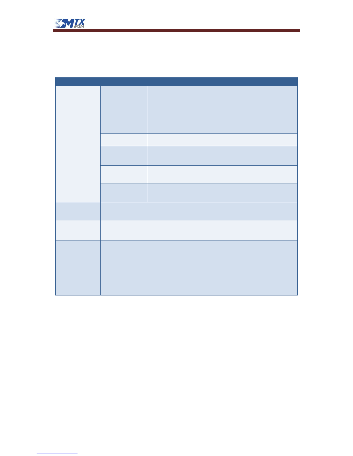
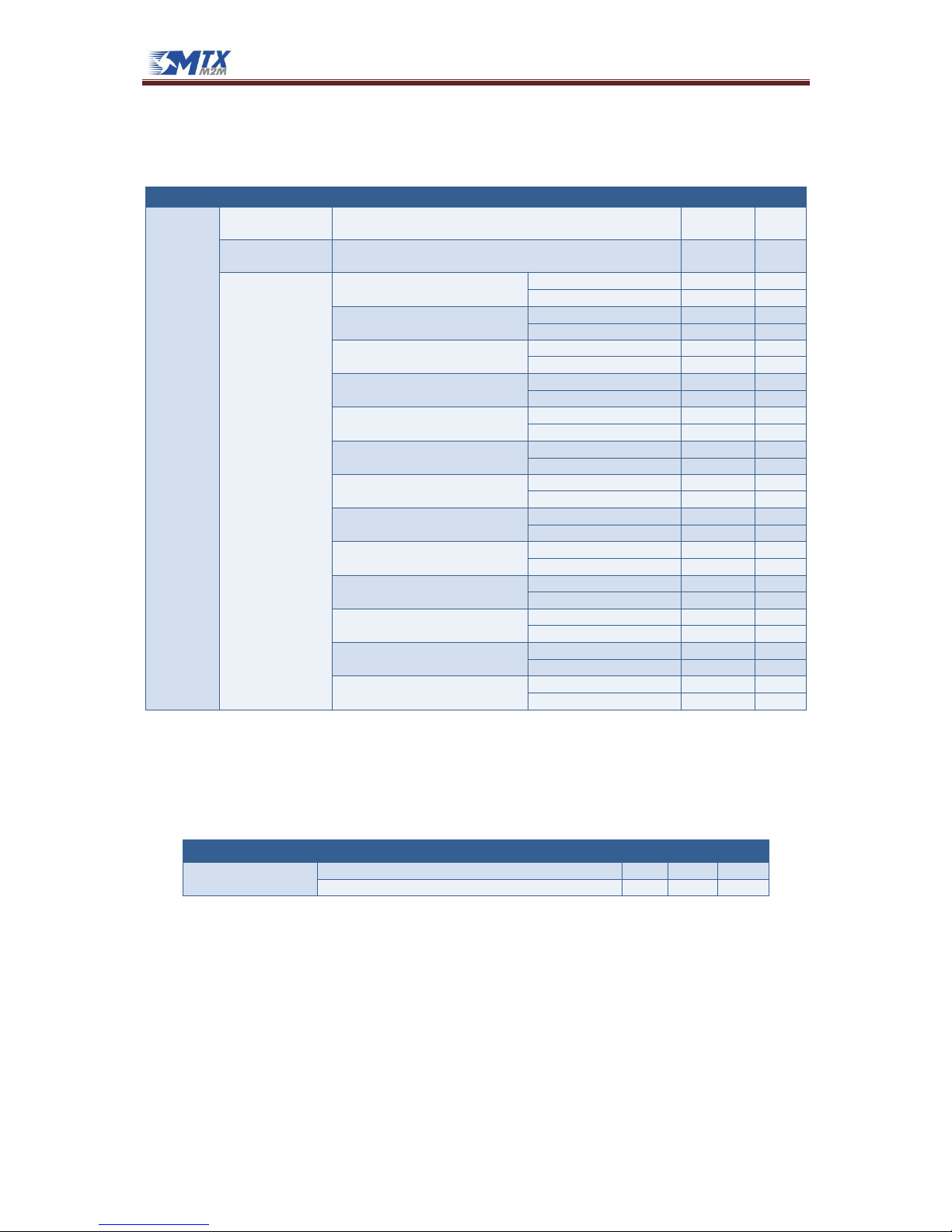
1.3 Features by model
Depending on the device model you have selected, there are a set of features available as described
in the table below. Please ask us at gsmsupport@matrix.es if you need any other combination of
features, or one that is not listed here.
MTX-65i
MTX-65i-BAT
MTX-65i-RS485
MTX-65i-RS485-LC
MTX-65i+G V6
MTX-65i+G+B V7
MTX-65i-ULP
RS232 (8-wire)
X X
RS232 (4-wire)
X X X X X X
RS232 (2-wire)
X
RS485
X X
USB
X X X X X X X
I2C
X X X X X X X
ADC
x2 x2 x2 x2 x2 x2 x1
DAC
x1 x1
GPIO
x4 x1 x1 x1 x5
Optoisolated IO
x6 x4 x6 x6
Accelerometer
X *2 X
RTC
X X X X X X X
Sleep mode
X * 1 X X
Ultra Low Power mode
X
Wake Up (by RTC)
X * 1 X X X
Wake Up (by Accelerometer)
X X X
Power On (by RTC)
X
Power On (by Opto IO)
X
Li-Po Battery
X X
HD WatchDog
X X X
Auto On
X X X X X X X
Auto On disable
X X X X
GPS
X X
GPS/GLONASS
*3 *3 *3
*1: only if AUTO ON is disabled by hardware
*2: upon request
*3: GLONASS can be ordered upon request

MTX-65i Family
www.mtxm2m.com www.matrix.es 2015/04 v3.4 Page 11/106
MTX Terminals® by MATRIX ELECTRONICA S.L.U
1.4 Differences between MTX-65i+G V6 and MTX-65+G V3
MTX-65i+G V6 is an enhanced version of the old MTX-65+G V3 modem, with full backwards
compatibility but with differences in its functional features
Internal Hardware Watchdog
A hardware watchdog can be used to restart the module inside. By default, the watchdog is not
active. It is handled by two GPIOs.
MTX-65+g V6 has a new internal hardware watchdog component which allows the module to be
reset when the internal Java program is not refreshed in a period of 120 seconds, meaning that it
hang-ups or does not respond in this time.
The internal GSM module has been changed from TC65 to TC65i:
o ARM9 MTX65i+G V6 vs. ARM7 in MTX-65+G V3. More computational power
o Operational temperature range has been extended to support restricted operation
down to -40ºC
o Lower current consumption in all sleep modes, cut down to less than the half the
range of TC65. When in Idle mode, the current is about 40% lower than TC65
o In transfer modes the current consumption has been minimized by up to 50%
depending the connection type
o Manufacturer Name, USB Vendor ID changed from Siemens to Cinterion
o With TC65i, Cinterion introduces an improved multiband selection procedure.
o TC65i provides dedicated Java APIs for direct access to module interfaces: I2C, SPI,
DAC and ADC.
o Simple AGPS feature
The internal GPS module has been changed
o A Condor C1216 GS module can be put in low power and active mode with the NMEA
command
o NMEA command for GPS antenna supervision is available
o Better sensitivity. 5Hz update rate
Added I2C bus IO expander chip (optional)

MTX-65i Family
www.mtxm2m.com www.matrix.es 2015/04 v3.4 Page 12/106
MTX Terminals® by MATRIX ELECTRONICA S.L.U
MTX-65+G V3
MTX-65i+G V6
Cinterion module
XT65 rel. 2
TC65i rel. 2
API for I2C, SPI, DAC, ADC
No
Yes
Transparent TCP Service
No
Yes
TLS/SSL for TCP Client, Transparent TCP
and HTTP
No
Yes
Tunneling mode
Only transparent GPS
mode
Yes
Informal network scan (without SIM)
No
Yes
SMS based diagnostics
No
Yes
GPS inside
ANTARIS 4
C1216 (Trimble)
AT commands to use GPS
AT^SGPSS, AT^SGPSC,
AT^SGPSP, AT^SGPSR
Not supported
Location APS (JSR179)
for GPS
Java Location API
The package
com.cinterion.location
includes a Location API to
support external GPS
applications:
- Coordinates Class
- Landmark Class
- LandmarkStore Class
- QualifiedCoordinates Class
- AddressInfo Class
Custom Options
TC65i-X:
- 2MB RAM
- 8MB flash
- FOTA without external
memory
I2c chip to GPIO extender:
- Switch off/on the GPS
- Control second watchdog
Battery and accelerometer
MTX-65+G+B V5
MTX-65i+G+B V7
MTX-TUNNEL GPS
v2.5
v2.8

MTX-65i Family
www.mtxm2m.com www.matrix.es 2015/04 v3.4 Page 13/106
MTX Terminals® by MATRIX ELECTRONICA S.L.U
1.5 Highlights
Interfaces
GSM FME M antenna connector
GPS SMA F antenna connector (*)
USB 2.0 High Speed port up to 480Mbps
SIM card interface 1.8V and 3V
DB9 female connector: complete 8-wire RS232 modem interface (*)
DB15 female connector:
o 1x RS232 (2 or 4-wire) port
o 1x I2C port
o 5x GPIO (*)
o 6x Optoisolated I/Os (*)
o 2x analog inputs (*)
o 1x analog output (*)
1x RS485 port (5-way plug-in terminal block) (*)
Operating status LEDs
Audio handset interface (RJ11 connector) (*)
Plug-in power supply (RJ11 connector)
General features
Quad band GSM/GPRS 850/900/1800/1900MHz
GPRS multislot class 12, GSM release 99
Output power:
o Class 4 (2W) for EGSM850 & EGSM900
o Class 1 (1W) for GSM1800 & GSM1900
SIM Application Toolkit, 3GPP release 99
Control via AT commands (Hayes, 3GPP TS 27.007, TS 27.005)
TCP/IP stack access via AT commands
Internet services: TCP, UDP, HTTP, FTP, SMTP, POP3
Power consumption at 12V (average)
o Ultra Low Power: 2.5µA (*)
o Sleep mode: 7mA (*)
o Idle (USB active): 17mA
o Speech mode (850/900MHz): 98.3mA
o GPRS class 12 (850/900MHz): 201mA
Operating temperature range: -30ºC to +80ºC
Dimensions, excluding connectors: 78.1 x 66.8 x 37.2mm
Weight: < 190 g
IP30 enclosure
Internal Hardware Watchdog (*)
Internal 1650mAh Li-Po battery (*)
3-Axis Accelerometer (±2g/±4g/±8g) (*)
Powered by Cinterion TC65i module

MTX-65i Family
www.mtxm2m.com www.matrix.es 2015/04 v3.4 Page 14/106
MTX Terminals® by MATRIX ELECTRONICA S.L.U
Drivers
RIL driver for Microsoft® Windows CE™ based devices
Multiplex Driver driver for Microsoft® Windows and Linux
Specifications
GPRS data transmission
o GPRS class 12
o Mobile station class B
o PBCCH support
o Coding schemes CS 1-4
CSD data transmission
o Up to 14.4kbps
o V.110
o Non-transparent mode
o USSD support
Voice features
o Triple-rate codec for HR, FR and EFR
o Adaptive multirate AMR
o Basic hands-free operation
o Echo cancellation
o Noise reduction
SMS
o Point-to-point MO and MT
o SMS cell broadcast
o Text and PDU mode
JavaTM features
JavaTM profile IMP-NG & CLDC 1.1 Hl, GPS support
Multi-threading programming and program execution
Memory space for Java applications: 1.7MB RAM & 8MB Flash
Special features
Secure data transmission with HTTPS, SSL and PKI
Serial interface modem for Microsoft® 7
TM
/XPTM/VistaTM
RLS Monitoring (Jamming detection)
Firmware update via USB/RS232
Integrated Firmware Update Over The Air (FOTA), configurable and royalty free
TLS for IP over AT
Tunneling mode for external serial devices
Real time clock with alarm functionality
Informal Network Scan
*: depending on model, see Section 1.3
MTX-65i Family
www.mtxm2m.com www.matrix.es 2015/04 v3.4 Page 15/106
MTX Terminals® by MATRIX ELECTRONICA S.L.U
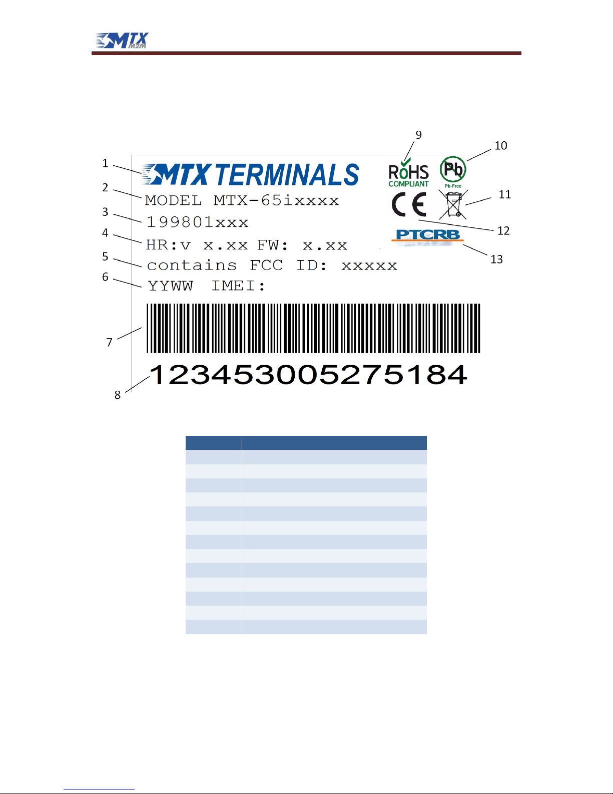
1.6 Product label
The label fixed to the bottom of a MTX Terminal comprises the following information:
No.
Information
1
MTX Terminals logo
2
Product name (model)
3
Product ordering number
4
Hardware and Firmware Revisions
5
FCC ID
6
Year/Week of fabrication
7
Barcode (Code 128) (IMEI)
8
Product IMEI
9
RoHS symbol
10
Pb-Free symbol
11
WEEE symbol
12
CE logo
13
PTCRB Certification logo
MTX-65i Family
www.mtxm2m.com www.matrix.es 2015/04 v3.4 Page 16/106
MTX Terminals® by MATRIX ELECTRONICA S.L.U
1.7 Main features and services
The MTX-65i performs a set of telecom services (TS) according to GSM standard phase 2+, ETSI and
ITU-T. The services and functions of the MTX-65i are implemented by issuing customized applications
embedded on the device, by AT commands issued internally or over the USB, RS232 or RS485
interface.
1.7.1 Key features at a glance
The MTX-65i is a GSM/GPRS band mobile station with the characteristics shown in the table below.
Feature
Implementation
General
Frequency bands
GSM/GPRS: Quad band, 850/900/1800/1900MHz
GSM class
Small MS
Output power
Class 4 (+33dBm ±2dB) for EGSM850
Class 4 (+33dBm ±2dB) for EGSM900
Class 1 (+30dBm ±2dB) for GSM1800
Class 1 (+30dBm ±2dB) for GSM1900
The values stated above are maximum limits. According to Release 99, the maximum output power in
a multislot configuration may be lower. The nominal reduction of maximum output power varies with
the number of uplink timeslots used and amounts to 2.0dB for 2Tx, 4.0dB for 3Tx and 6.0dB for 4Tx.
Power supply
Single supply voltage
Maximum: 6.5 to 40V (without damage the device)*
Recommended: 7 to 35V
*(Device operation from 6.5 to 7V is not guaranteed over the whole temperature range / Supplies from 35 to 40V
may damage the device during a extended use)
Physical
Dimensions: 78,1 x 66,8 x 37,2 mm Weight: approx. 190g
RoHS
All hardware components are fully compliant with the EU RoHS Directive
GSM / GPRS features
Data transfer
GPRS
Multislot Class 12
Full PBCCH support
Mobile Station Class B
Coding Scheme 1 – 4
CSD
V.110, RLP, non-transparent
9.6kbps
USSD
PPP-stack for GPRS data transfer
SMS
Point-to-point MT and MO
Cell broadcast
Text and PDU mode
Storage: SIM card plus 25 SMS locations in mobile equipment
Transmission of SMS alternatively over CSD or GPRS. Preferred mode can be user defined
Fax
Group 3; Class 1
Audio
Speech codecs:
Half rate HR (ETS 06.20)
Full rate FR (ETS 06.10)
Enhanced full rate EFR (ETS 06.50/06.60/06.80)
Adaptive Multirate AMR

MTX-65i Family
www.mtxm2m.com www.matrix.es 2015/04 v3.4 Page 17/106
MTX Terminals® by MATRIX ELECTRONICA S.L.U
Line echo cancellation, noise reduction, DTMF, 7 ringing tones
Software
AT commands
Hayes, 3GPP TS 27.007, 27.005, Gemalto M2M
JavaTM Open
Platform
JavaTM Virtual Machine with APIs for amongst others AT Parser, Serial Interface, FlashFile System and
TCP/IP Stack.
Major benefits: seamless integration into Java applications, ease of programming, no need for
application microcontroller, extremely cost-efficient hardware and software design – an ideal
platform for industrial GSM applications.
The memory space available for Java programs is around 1.7MB in the flash file system and around
6MB RAM. Application code and data share the space in the flash file system and in the RAM.
SIM Application
Toolkit
SAT Release 99
TCP/IP stack
Access by AT commands
Remote SIM
Access
MTX-65i supports Remote SIM Access. RSA enables MTX-65i to use a remote SIM card via its serial
interface and an external application, in addition to the SIM card locally attached to the modem. The
connection between the external application and the remote SIM card can be a Bluetooth wireless
link or a serial link. The necessary protocols and procedures are implemented according to the “SIM
Access Profile Interoperability Specification of the Bluetooth Special Interest Group”
Firmware update
Firmware update from host application over RS232/USB. Over-the-air (OTA) firmware is also possible.
Interfaces (depending on models)
USB
Supports a USB 2.0 High Speed (480Mbit/s) device interface, Full Speed (12Mbit/s) compliant
RS232 (8-wire)
Adjustable baud rates: 1200bps to 921600bps
Autobauding: 1200 to 230400bps
Supports RTS/CTS hardware flow control
Multiplex ability according to GSM 07.10 Multiplexer Protocol
RS232 (4-wire)
Adjustable baud rates: 1200bps to 921600bps
Autobauding: 1200 to 230400bps
Supports RTS/CTS hardware flow control
Multiplex ability according to GSM 07.10 Multiplexer Protocol
RS485
Adjustable baud rates: 1200bps to 921600bps
Autobauding: 1200 to 230400bps
Half-duplex
I2C interface
Supports I2C serial interface up to 400kbps
Audio
RJ11 connector provides balanced analog inputs and outputs for a microphone and an earpiece.
GPIO
Up to 5 GPIO lines and 6 Optoisolated I/O’s
ADC
Up to 2 analog-to-digital converters
DAC
1 digital-to-analog converter
Status
Bi-colour LED to indicate network connectivity status.
UICC interface
Supported chip cards: UICC/SIM/USIM 3V, 1.8V
Antenna
50 Ohms. GSM/UMTS main antenna
Power on/off, Reset
Power on/off
Automatic switch-on at power supply
Switch off by AT command
Switch off by hardware signal TURN_OFF
Automatic switch-off in case of critical temperature or voltage conditions
Software Reset
Orderly shutdown and reset by AT command
Hardware Reset
Emergency reset by hardware signal TURN_OFF
Special features
Antenna
SAIC (Single Antenna Interference Cancellation) / DARP (Downlink Advanced Receiver Performance)
Rx Diversity (receiver type 3i – 64-QAM) / MIMO
MTX-65i Family
www.mtxm2m.com www.matrix.es 2015/04 v3.4 Page 18/106
MTX Terminals® by MATRIX ELECTRONICA S.L.U
1.7.2 Operating modes
The table below briefly summarizes the various operating modes referred to in the following
chapters.
Limits
Function
Normal operation
GSM / GPRS
SLEEP
Various power saving modes set using the AT+CFUN command. Software
is active to a minimum extent. If the modem was registered to the GSM
network in IDLE mode, it is registered and paging with the BTS in SLEEP
mode too. Power saving can be chosen at different levels: the NONCYCLIC SLEEP mode (AT+CFUN=0) disables the AT interface. The CYCLIC
SLEEP modes AT+CFUN=7 and 9 can be used to alternately activate and
deactivate the AT interfaces to allow permanent access to all AT
commands.
GSM IDLE
Software is active. Once registered to the GSM network, paging with BTS
is carried out. The modem is ready to send and receive.
GSM TALK
Connection between two subscribers is in progress. Power consumption
depends on the individual settings of network coverage such as DTX
off/on, FR/EFR/HR, hopping sequences, and antenna.
GPRS IDLE
Terminal is ready for GPRS data transfer, but no data is currently sent or
received. Power consumption depends on network settings and GPRS
configuration (e.g. used multislot settings).
GPRS DATA
GPRS data transfer in progress. Power consumption depends on network
settings (e.g. power control level), uplink / downlink data rates and
GPRS configuration (e.g. used multislot settings).
Sleep mode
Normal shutdown after sending the AT^SMSO command. The internal GSM engine enters in a
power down mode where only a voltage regulator is active for powering the internal RTC.
Software is not active. Interfaces are not accessible.
Ultra Low Power
mode
Only available in MTX-65i-ULP modems. All the electronic systems remain disconnected from the
power supply input, with the exception of a little piece of logic which allows for waking up the
modem again.
Airplane mode
Airplane mode shuts down the radio part of the modem, causes the modem to log off from the
GSM/GPRS network, and disables all AT commands whose execution requires a radio connection.
Airplane mode can be controlled by using the AT commands AT^SCFG and AT+CALA:
With AT^SCFG=MEopMode/Airplane/OnStart, the modem can be configured to enter
Airplane mode each time it is switched on or reset
The parameter AT^SCFG=MEopMode/Airplane can be used to switch back and forth
between Normal mode and Airplane mode at any point during operation.
Setting an alarm with AT+CALA followed by AT^SMSO wakes the modem up into
Airplane mode at the scheduled time.
MTX-65i Family
www.mtxm2m.com www.matrix.es 2015/04 v3.4 Page 19/106
MTX Terminals® by MATRIX ELECTRONICA S.L.U
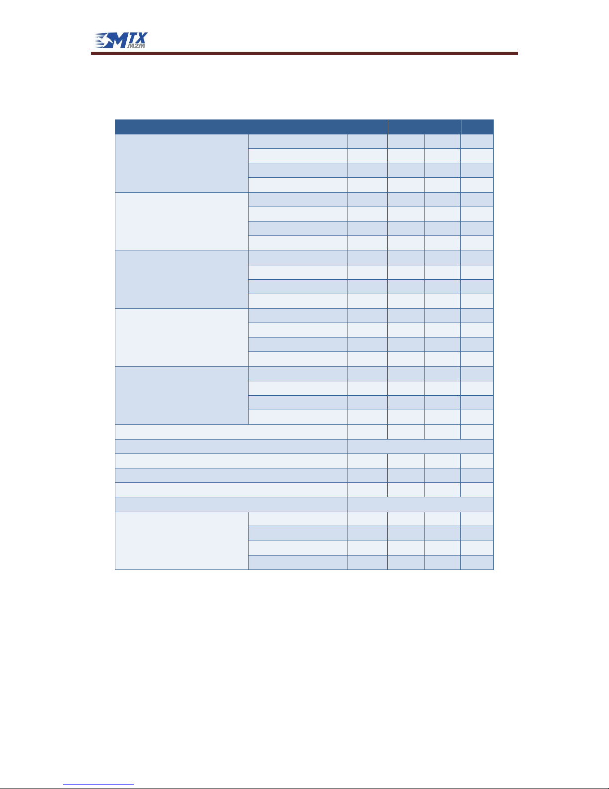
1.7.3 Power Consumption
It is recommended to use 12V/1.5A power supply.
Description
Conditions
Typical
Unit
IIN1
ULP mode supply
current
Ultra Low Power Mode
2.5
µA
Sleep mode supply
current
Internal GSM module powered down
7
mA
GSM/GPRS supply
current
IDLE (UART activated but no
communication)
USB disconnected
13
mA
USB active
17
mA
GSM call (GSM850/900;
P
RFOUT
=2W; 1Tx/1Rx; ROPR=1..3)
Average
98.3
mA
Burst
553
mA
GPRS Class 8 (GSM850/900;
P
RFOUT
=2W; 1Tx/4Rx; ROPR=1..3)
Average
95
mA
Burst
553
mA
GPRS Class 10 (GSM850/900;
P
RFOUT
=2W; 2Tx/3Rx; ROPR=1)
Average
170
mA
Burst
553
mA
GPRS Class 10 (GSM850/900;
P
RFOUT
=1W; 2Tx/3Rx; ROPR=2/3)
Average
143
mA
Burst
451
mA
GPRS Class 12 (GSM850/900;
P
RFOUT
=1W; 4Tx/1Rx; ROPR=1)
Average
201
mA
Burst
382
mA
GPRS Class 12 (GSM850/900;
P
RFOUT
=0.5W; 4Tx/1Rx; ROPR=2/3)
Average
170
mA
Burst
307
mA
GSM call (GSM1800/1900;
P
RFOUT
=1W; 1Tx/1Rx; ROPR=1..3)
Average
75
mA
Burst
348
mA
GPRS Class 8 (GSM1800/1900;
P
RFOUT
=1W; 1Tx/4Rx; ROPR=1..3)
Average
75
mA
Burst
348
mA
GPRS Class 10 (GSM1800/1900;
P
RFOUT
=1W; 2Tx/3Rx; ROPR=1)
Average
116
mA
Burst
348
mA
GPRS Class 10 (GSM1800/1900;
P
RFOUT
=0.5W; 2Tx/3Rx; ROPR=2/3)
Average
102
mA
Burst
297
mA
GPRS Class 12 (GSM1800/1900;
P
RFOUT
=0.5W; 4Tx/1Rx; ROPR=1)
Average
143
mA
Burst
245
mA
GPRS Class 12 (GSM1800/1900;
P
RFOUT
=0.25W; 4Tx/1Rx;ROPR=2/3)
Average
133
mA
Burst
218
mA
1. With an impedance of Z
LOAD
=50Ohm at the antenna port.
2. Measurements start 6 minutes after switching ON the modules
Average times: SLEEP and ULP mode – 3 minutes, transfer modes – 1.5 minutes
Communication tester settings: no neighbor cells, no cell reselection etc., RMC (reference measurement channel)
Description
Conditions
Typ
Max
Unit
ULP mode supply
current
TA = 25ºC
2.5 5 µA
TA = 85ºC
8.5
34
µA
MTX-65i Family
www.mtxm2m.com www.matrix.es 2015/04 v3.4 Page 20/106
MTX Terminals® by MATRIX ELECTRONICA S.L.U
1.7.4 RF antenna interface description
The table below briefly summarizes the RF Antenna interface GSM/UMTS
Parameter
Conditions
Min.
Typical
Max.
Unit
Frequency range
Uplink (MS → BTS)
GSM 850
824 849
MHz
EGSM 900
880 915
MHz
GSM 1800
1710 1785
MHz
GSM 1900
1850 1910
MHz
Frequency range
Uplink (BTS → MS)
GSM 850
869 894
MHz
EGSM 900
925 960
MHz
GSM 1800
1805 1880
MHz
GSM 1900
1930 1990
MHz
RF Power @ ARP with 50Ohm Load
GSM 850
31
33
35
dBm
EGSM 9001
31
33
35
dBm
GSM 18002
28
30
32
dBm
GSM 1900
28
30
32
dBm
Number of carriers
GSM 850
124
EGSM 900
174
GSM 1800
374
GSM 1900
299
Duplex spacing
GSM 850
45 MHz
EGSM 900
45 MHz
GSM 1800
95 MHz
GSM 1900
80 MHz
Carrier spacing
200 kHz
Multiplex, Duplex
TDMA/FDMA, FDD
Time slots per TDMA frame
8
Frame duration
4.615
ms
Time slot duration
577 µs
Modulation
GMSK
Static Receiver Input Sensitivity @
ARP
GSM 850
-102
-108 dBm
EGSM 900
-102
-108 dBm
GSM 1800
-102
-107 dBm
GSM 1900
-102
-107 dBm
1. Power control level PCL 5
2. Power control level PCL 0

MTX-65i Family
www.mtxm2m.com www.matrix.es 2015/04 v3.4 Page 21/106
MTX Terminals® by MATRIX ELECTRONICA S.L.U
1.7.5 SIM Card
The MTX-65i family supports an external SIM card through the integrated SIM holder. Both 3V and
1.8V SIM technology is supported. The older 5V SIM technology is not supported.
1.8 Precautions
MTX-65i as a standalone item is designed for indoor use only. For outdoor use it must be integrated
into a weatherproof enclosure. Do not exceed the environmental and electrical limits as specified in
Technical Data

MTX-65i Family
www.mtxm2m.com www.matrix.es 2015/04 v3.4 Page 22/106
MTX Terminals® by MATRIX ELECTRONICA S.L.U
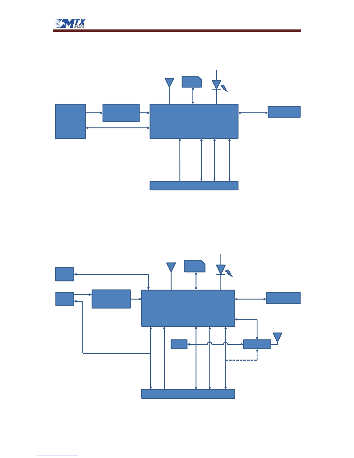
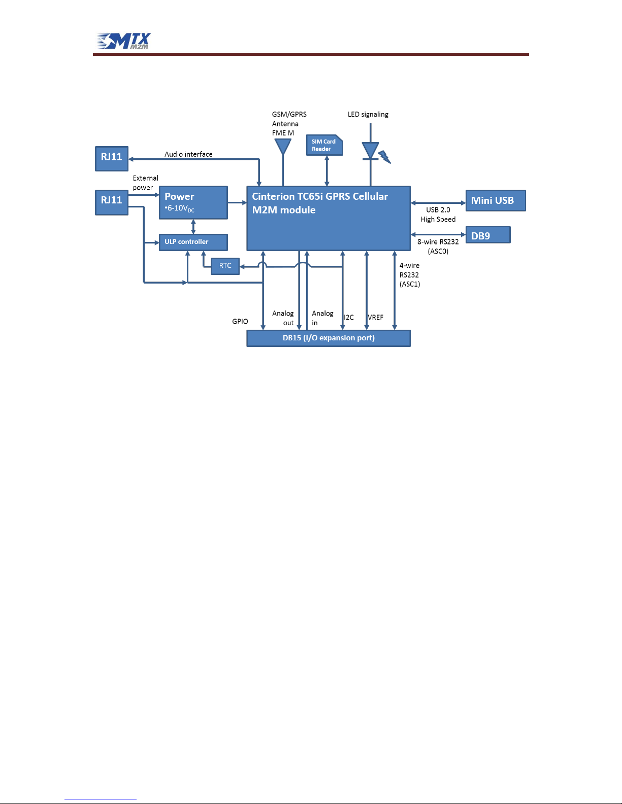
1.9 Block diagram
1.9.1 MTX-65i
The base MTX-65i modem’s block diagram is shown in the following figure:
1.9.2 MTX-65i-RS485
The MTX-65i-RS485 modem’s block diagram is shown in the following figure:
Cinterion TC65i GPRS Cellular
M2M module
Power
•6.5-40V
DC
SIM Card
Reader
GSM/GPRS
Antenna
FME M
USB 2.0
HighSpeed
External
power
LED signaling
8-wire RS232
(ASC0)
DB9
Mini USB
DB15 (I/O expansion port)
I2C
SPI
Analog
in
Analog
out
GPIO
RJ11
2-wire
RS232
(ASC1)
VREF
RJ11
Audio interface
Cinterion TC65i GPRS Cellular
M2M module
Power
•6.5-40V
DC
SIM Card
Reader
GSM/GPRS
Antenna
FME M
USB 2.0
HighSpeed
External
power
LED signaling
RS485 (ASC1)
Mini USB
DB15 (I/O expansion port)
I2C
Analog
in
Opto I/O
Plug-in
5-way
terminal
block
4-wire
RS232
(ASC0)
VREF
MTX-65i Family
www.mtxm2m.com www.matrix.es 2015/04 v3.4 Page 23/106
MTX Terminals® by MATRIX ELECTRONICA S.L.U
1.9.3 MTX-65i-RS485-LC
The MTX-65i-RS485-LC modem’s block diagram is shown in the following figure:
1.9.4 MTX-65i+G V6, MTX-65i+G+B V7 and MTX-65i-BAT
The MTX-65i+G V6 and MTX-65i+G+B V7 modem’s block diagram is shown in the following figure:
Note: MTX-65i-BAT does not include the GPS module
Cinterion TC65i GPRS Cellular
M2M module
Power
•6.5-40V
DC
SIM Card
Reader
GSM/GPRS
Antenna
FME M
USB 2.0
HighSpeed
External
power
LED signaling
RS485 (ASC1)
Mini USB
DB15 (I/O expansion port)
I2C
Analog
in
Plug-in
5-way
terminal
block
4-wire
RS232
(ASC0)
VREF
Cinterion TC65i GPRS Cellular
M2M module
Power
•6.5-40V
DC
SIM Card
Reader
GSM/GPRS
Antenna
FME M
USB 2.0
HighSpeed
External
power
LED signaling
Mini USB
DB15 (I/O expansion port)
Accel
I2C
Analog
in
GPIO &
Opto I/O
RJ11
4-wire
RS232
(ASC0)
VREF
GPS module
ASC1
RJ11
Audio interface
MTX-65i Family
www.mtxm2m.com www.matrix.es 2015/04 v3.4 Page 24/106
MTX Terminals® by MATRIX ELECTRONICA S.L.U
1.9.5 MTX-65i-ULP
The general MTX-65i-ULP modem’s block diagram is shown in the following figure:
MTX-65i Family
www.mtxm2m.com www.matrix.es 2015/04 v3.4 Page 25/106
MTX Terminals® by MATRIX ELECTRONICA S.L.U
1.10 Hardware revisions
MTX-65i
Hardware Revision
Starting production date
Changes
2.03
01/2014
Initial version
MTX-65i-ULP
Hardware Revision
Starting production date
Changes
2.03
01/2014
Initial version
2.03.01
06/2014
DB15 connector: functionality of pins 9 and 10 is
switched:
Before: pin 9 → VEXT, pin 10 → DAC_OUT
Now: pin 9 → DAC_OUT, pin 10 → VEXT
MTX-65i-RS485 and MTX-65i-RS485-LC
Hardware Revision
Starting production date
Changes
1.02
01/2014
Initial version
MTX-65i+G V6 and MTX-65i+G+B V7
Hardware Revision
Starting production date
Changes
5.02
01/2014
Initial version
MTX-65i Family
www.mtxm2m.com www.matrix.es 2015/04 v3.4 Page 26/106
MTX Terminals® by MATRIX ELECTRONICA S.L.U
2. Mechanical description
2.1 MTX-65i and MTX-65i-ULP
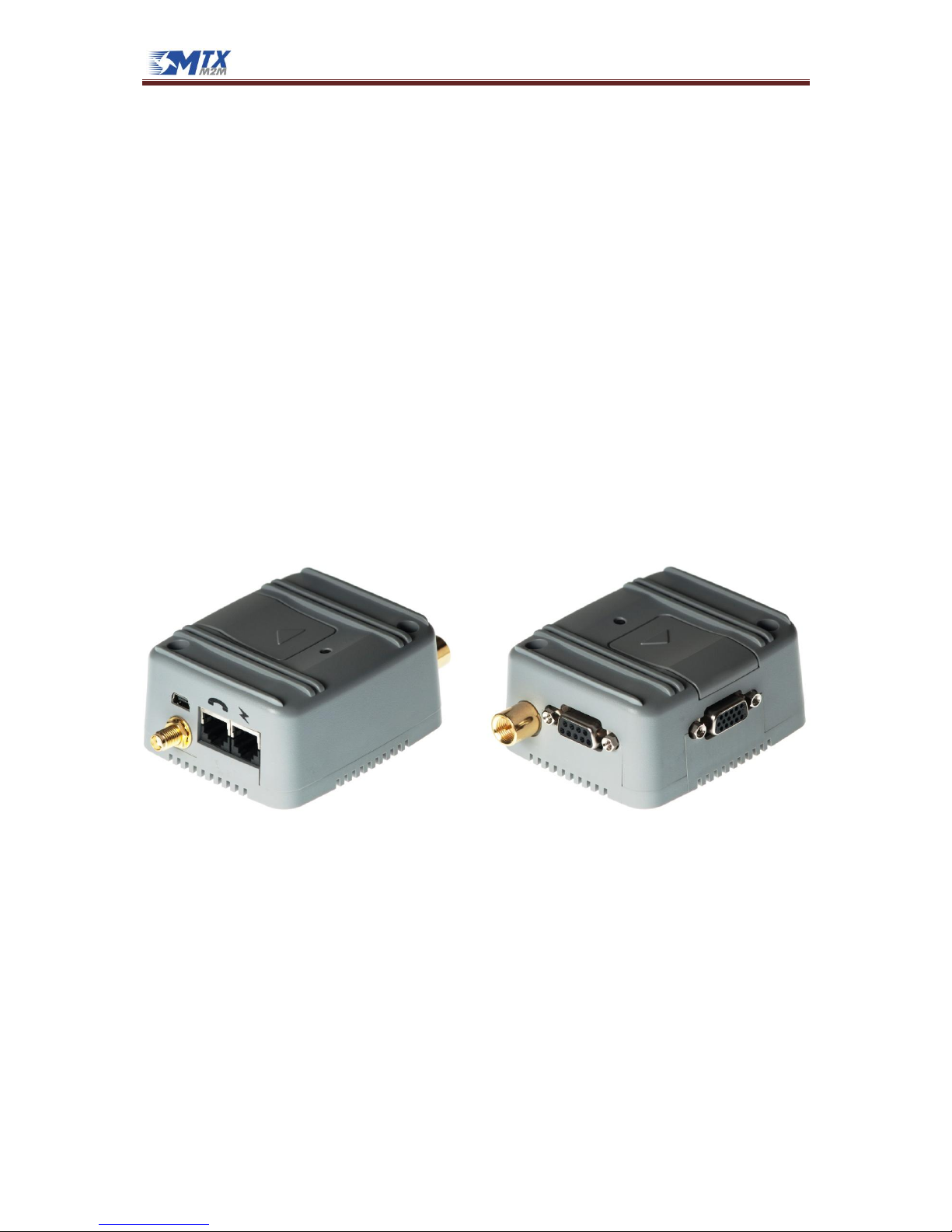
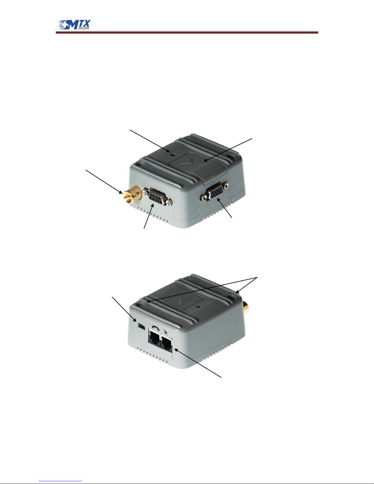
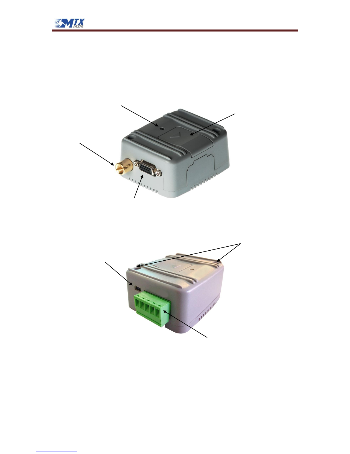
2.1.1 Overview
The pictures below show the mechanical design of the modem along with the positions of the
different connectors and mounting holes. The modem case is made of durable PC/ABS plastic.
Mini USB 2.0 Connector
Mounting holes
Power Supply Connector
Bi-color Led Indicator
SIM Card Reader
Antenna Connector
DB15 connector
DB9 connector
MTX-65i Family
www.mtxm2m.com www.matrix.es 2015/04 v3.4 Page 27/106
MTX Terminals® by MATRIX ELECTRONICA S.L.U
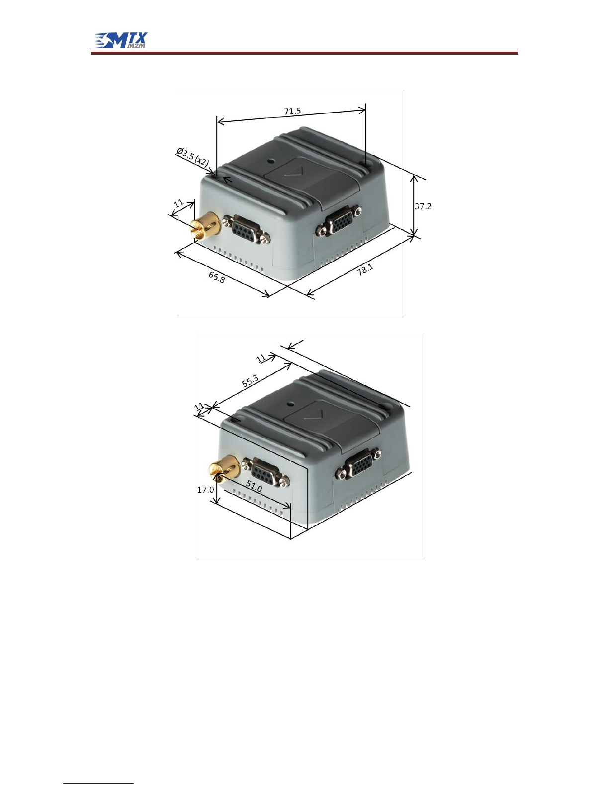
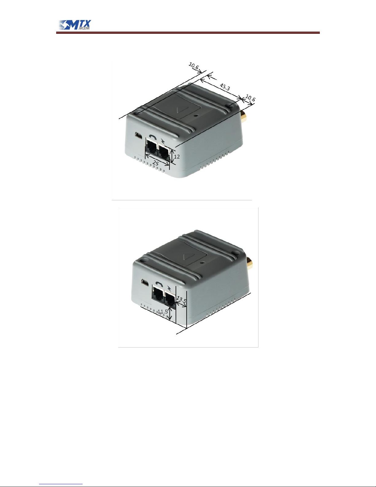
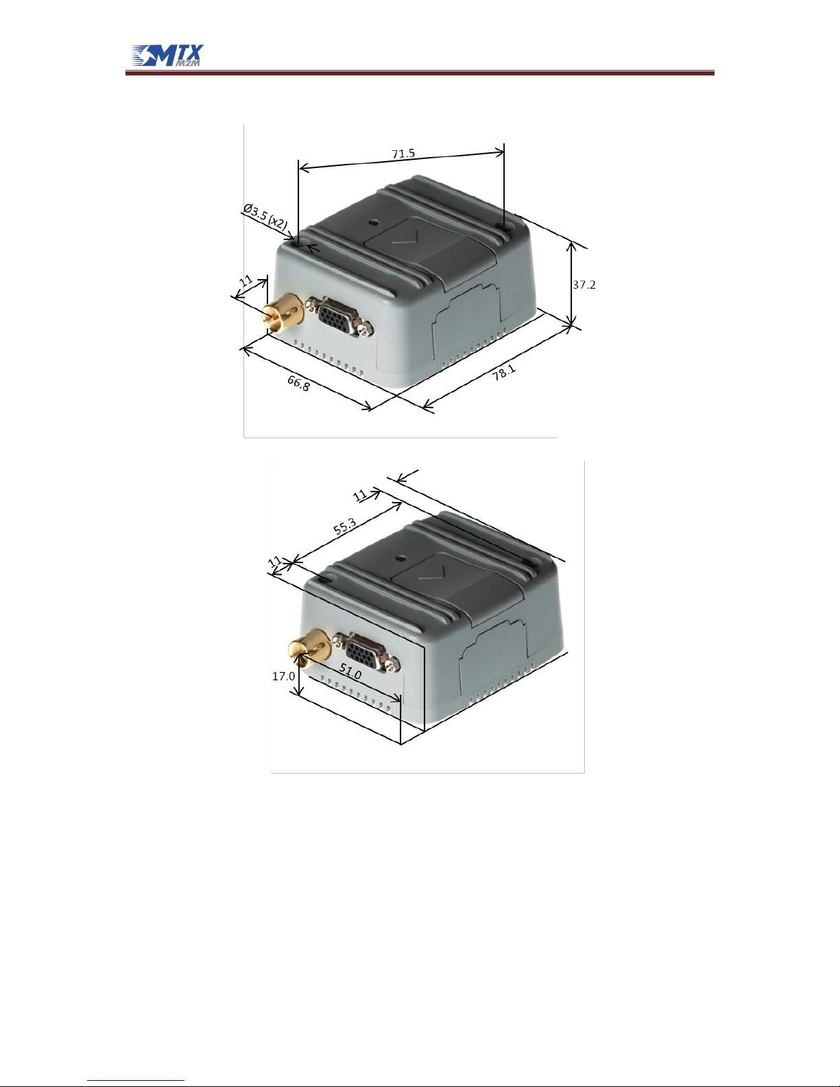
2.1.2 Dimensions
All dimensions are in millimeters
MTX-65i Family
www.mtxm2m.com www.matrix.es 2015/04 v3.4 Page 28/106
MTX Terminals® by MATRIX ELECTRONICA S.L.U
All dimensions are in millimeters
MTX-65i Family
www.mtxm2m.com www.matrix.es 2015/04 v3.4 Page 29/106
MTX Terminals® by MATRIX ELECTRONICA S.L.U
2.2 MTX-65i-RS485 and MTX-65i-RS485-LC
2.2.1 Overview
The pictures below show the mechanical design of the modem along with the positions of the
different connectors and mounting holes. The modem case is made of durable PC/ABS plastic.
Mini USB 2.0 Connector
Mounting holes
Power Supply & RS485 Connector
Bi-color Led Indicator
SIM Card Reader
Antenna Connector
DB15 connector
MTX-65i Family
www.mtxm2m.com www.matrix.es 2015/04 v3.4 Page 30/106
MTX Terminals® by MATRIX ELECTRONICA S.L.U
2.2.2 Dimensions
All dimensions are in millimeters
 Loading...