


X4 Portable Gas Detection Instrument
Operators Manual
Version 1.3

E X S E N S T E C H NOLOG Y ( P T Y ) L T D
ExSens X4 Instrumentation
ExSens X4
ExSens Technology (Pty) Ltd
Phone: 011 397 1119 Fax: 086 425 0675
Volume 1.3 Updated 2019/05/28
1 | P a g e
© ExSens TECHNOLOGY (PTY) LTD2017

TABLE OF CONTENTS
SCOPE ............................................................................................................................................................................ 4
DOCUMENT OVERVIEW ................................................................................................................................................. 4
IDENTIFICATION............................................................................................................................................................. 4
1.1 SAFETY OVERVIEW .................................................................................................................................................... 4
1.2 INSTRUMENT DESCRIPTION ......................................................................................................................................... 9
1.3 INSTRUMENT NORMAL OPERATION .............................................................................................................................. 9
1.4 GRAPH SCREEN OPERATION ..................................................................................................................................... 14
1.5 MEASUREMESH OPERATION .................................................................................................................................... 15
1.6 OVER- RANGE ........................................................................................................................................................ 16
1.7 AUTO CALIBRATION ................................................................................................................................................ 16
1.8 PROGRAMMABLE OPTIONS ....................................................................................................................................... 16
1.9 WARRANTY AND LIABILITY ........................................................................................................................................ 18
TABLE OF FIGURES
FIGURE 1: INSTRUMENT ................................................................................................................................................... 8
FIGURE 2: CHARGING DISPLAY SCREEN .......................................................................................................................... 9
FIGURE 3: LOGO DISPLAY SCREEN ............................................................................................................................. 10
FIGURE 4: NORMAL DISPLAY ........................................................................................................................................ 10
FIGURE 5: CALIBRATION MENU...................................................................................................................................... 11
FIGURE 6: SENSOR ZERO SCREEN ................................................................................................................................ 12
FIGURE 7: CALIBRATION EDIT SCREEN.......................................................................................................................... 12
FIGURE 8: CALIBRATION SCREEN .................................................................................................................................. 13
FIGURE 9: MENU SCREEN .............................................................................................................................................. 13
FIGURE 10: GRAPH SCREEN .......................................................................................................................................... 14
FIGURE 11: AUTO CALIBRATE SCREEN ........................................................................................................................ 16
2 | P a g e
© ExSens TECHNOLOGY (PTY) LTD2017

Specification
Gas Types Flammable Toxic x 2 Oxygen
Sensors and measuring range CH4 = 0-100% LEL CO/H2S = 0-500/0-100ppm 0-25% by volume
Measuring principal Catalytic Combustion Electro-chemical Electro-chemical
Calibration gasses % = up to 50% full-scale ppm = 20-200 Bottled / Fresh Air
Response time T90 Less than 15 seconds Less than 35 seconds Less than 15 sec.
Resolution 0.1% < 6 ppm 0.1%
Long term drift ± 0.1% 2% Full scale /month 2% Full scale/month
Min & max pressure - 10 KPa to + 50 KPa Ambient ± 10% Ambient ± 10%
Max relative humidity 95 % Non-condensing
Sample velocity 20-40 liters per hour
Operating temperature -10 to + 40oC
Storage temperature 0 – 20oC
Power source * Battery pack 3.7 Volt 2,800 mAmp/hour
OR
*Battery pack 3.7 Volt 3.200 mAmp/hour
Operational time > than 12 hours
Real Time Clock accuracy < 10 ppm (< 0.32%)
Dimensions 125 x 75x 39 (mm)
Weight 320 g
Housing Polycarbonate with TPE over-mold
Warranty * 1 (one) year on all electronic parts and workmanship
* 6 (six) months on battery pack
* 3 (three) months on sensors fitted by OEM
Approval SANS/IEC 60079 Part 0: 2005
SANS/IEC 60079 Part 11: 2007
SANS/IEC 60079 Part 29 - 1
SANS 1515– 1
SANS 1515 – 3 part 1
User specification SANS/IEC 60079 Part 29 - 2
3 | P a g e
© ExSens TECHNOLOGY (PTY) LTD2017

SCOPE
The document outlines the use of the ExSens X4portableGas Detection Instrument capable of
detecting up to four gasses and displaying the readings on a graphic display. This document also
describes the capability of responding to commands on a serial and radio interface.
DOCUMENT OVERVIEW
This document contains all of the required operational information as needed by the client.
This document is intended to be the primary source of information to properly install and operate
the instrument described herein.
IDENTIFICATION
The document is intended for the portable gas detection instrument model X4 manufactured by
ExSens Technology. The instrument will be identified as the ExSens X4.
1.1 Safety Overview
It is imperative that the EXSENS X4 instrument be used as directed. All the “intrinsically safe”
parameters must also be adhered to for proper safe use of the equipment in potentially gaseous areas.
The safety of the person(s) that the instrument is protectingwill be dependent on the condition and
serviceability of the instrument.
It is, and remains the responsibility of the user to comply with the laws and regulations where the
instrument is used, in as much as it applies to the instrument and the use thereof.
Special Conditions for Safe Use of ExSens X4 Instrument
Location Zone 0 & 1 Gas/ Coal dust: Underground and Surface
Hazard Frequency --- Continuous, as could occur under normal
operating conditions in hazardous area
Environment Group I + H2 Methane and coal dust / plus Hydrogen
Limiting Temperature 450°C (Methane gas)
150°C (Coal dust)
Ambient Temperature -20°C to 40°C
The use of apparatus in hazardous locations is subject to the following provisions as
applicable, which shall be adhered to:
SANS 10086 requirements;
Any conditions mentioned in approval report, available on request;
Codes of Practice enforced in terms of Regulations 21.17.2 of Minerals Act, by Chief
Inspector of Mines;
Any restrictions and conditions enforced by Chief Inspectors of Mines, Principal Inspector
(Group I equipment) or Chief Inspector of Factories (Group II equipment);
Any relevant requirements of the MHS Act or the OHS Act.
4 | P a g e
© ExSens TECHNOLOGY (PTY) LTD2017

CONDITIONS OF CERTIFICATION:
US Market
Note 1: This ground penetrating UWB device shall be operated only when directed at the ground within one meter
of the surface under analysis.
Note 2: Operation under the provisions of this section is limited to GPRs and wall imaging systems operated for
purposes associated with law enforcement, fire fighting, emergency rescue, scientific research, commercial
mining, or construction.
Note 3: Devices used in the US must be coordinated with the FCC prior to use. Contact ExSens Technology
(Pty) Ltd for details regarding coordination.
Radiation Exposure Statement:
This equipment complies with FCC radiation exposure limits for portable devices. The equipment
meets the Specific Absorption Rate (SAR) exemption requirements of Part 2.1093.
When operating the device, a distance of at least 5mm shall be maintained from the body and the
radiating element.
5 | P a g e
© ExSens TECHNOLOGY (PTY) LTD2017

Canadian Market
Note 1: This Ground Penetrating UWB Device shall be operated only when directed at the ground within
one meter of the surface under analysis
Remarque 1: ce dispositif UWB pénétrant dans le sol ne doit être utilisé que lorsqu'il est dirigé vers le sol à
un mètre de la surface analysée
Note 2: This Ground Penetrating UWB Device shall be operated only by law enforcement agencies,
scientific research institutes, commercial mining companies, construction companies, and emergency
rescue or fire fighting organizations.
Remarque 2: Ce dispositif UWB de pénétration au sol ne doit être utilisé que par des organismes chargés
de l'application de la loi, des instituts de recherche scientifique, des sociétés minières commerciales, des
entreprises de construction et des organisations de secours et de lutte contre l'incendie.
Radiation Exposure Statement:
This equipment complies with ISED radiation exposure limits and meets the exemption
requirements per Section 2.5 of RSS-102. The test distance was ≤5mm.
Déclaration d'exposition aux radiations:
Cet équipement est conforme aux limites d'exposition au rayonnement ISED et aux
exigences en matière d'exemption selon la section 2.5 de la norme RSS-102. La distance
de test était ≤5mm.
6 | P a g e
© ExSens TECHNOLOGY (PTY) LTD2017

Gas/Vapor
Relative
Sensitivity*
Gas/Vapor
Relative
Sensitivity*
Methane
100
Carbon
110
Propane
60
Acetone
65
n-Butane
60
Methyl ethyl
50
n-Pentane
55
Toluene
45
n-Hexane
45
Ethyl acetate
50
n-Heptane
45
Hydrogen
105
n-Octane
40
Ammonia**
125
Methanol
90
Cyclohexane
55
Ethanol
70
Leaded Petrol
55
Iso-propyl alcohol
55
Unleaded petrol
55
Acetylene
80
Ethylene
90
1, 3 Butadiene
55
CONDITIONS OF MANUFACTURE
The battery protection circuit must be fully encapsulated.
The fuses must be fully encapsulated.
SPECIAL CONDITIONS OF SAFE USE (X)
To maintain the IP rating, all screws must be fitted and tightened to the correct
specification.
Do not charge in hazardous area.
Cross Sensitivity of Flammable Sensor when calibrated for Methane
7 | P a g e
© ExSens TECHNOLOGY (PTY) LTD2017
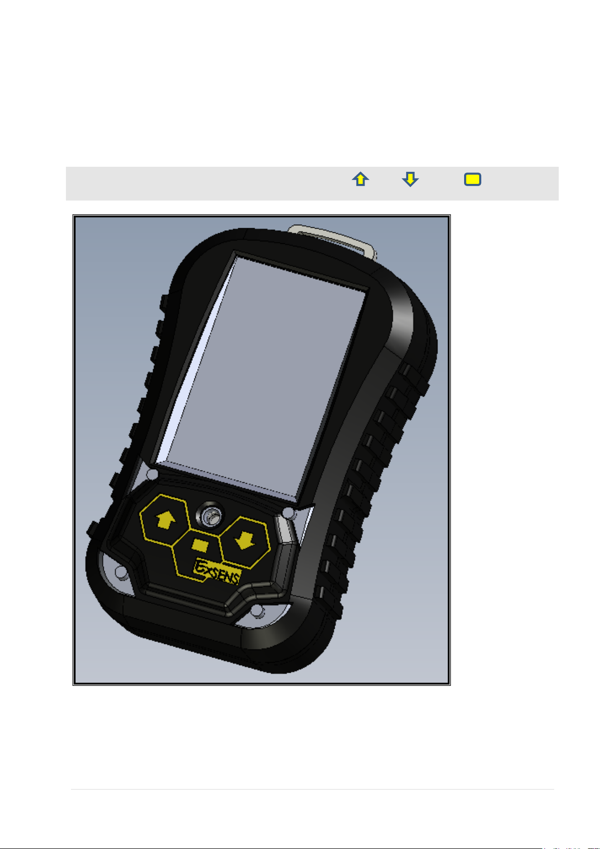
Instrument functionality
NOTE: The EXSENS X4 instrument hasthree buttons (UP , DWN and ENT ) to access all
of the functional menus.
Figure 1: Instrument
8 | P a g e
© ExSens TECHNOLOGY (PTY) LTD2017

1.2 Instrument description
The instrument housing is made of semi opaque molded polycarbonate with black TPE over-mold. The
housing is held together with 6 x M3 stainless steelcap screws. The housing with its TPE over-mold will
form a natural seal between the two halves of the housing.
The instrument is capable of displaying up to four different gas readings on a color graphic display.
The instrument is intended for use as a continuous measuring device for portable and handheld
applications. The instrument can be worn on the waist belt of a worker by means of a leather carry
pouch (sold separately, please consult with your accredited distribution agent).
1.3 Instrument Normal Operation
When placed on the charger, the instrument will initiate its boot sequence.Upon a successful boot the
“logos” will be displayed and the instrument will go to charging mode.
While charging, the instrument will display the battery charging screen until removed from the charger.
Figure 2: Charging display screen
Upon removal from the charger, the instrument will re-boot and do all the required self-tests. Each
check will be displayed and shown as passed or failed. If any of the tests fail the user should return the
instrument to an instrument repair technician.DO NOT USE INSTRUMENT IF ANY OF THE TESTS
HAS FAILED.
RTC / BATTERY: PASS / FAILED
SYSTEM RAM: PASS / FAILED
SYSTEM CLOCK: PASS / FAILED
AtoD CONVERTER: PASS / FAILED
SD CARD: PASS / FAILED
9 | P a g e
© ExSens TECHNOLOGY (PTY) LTD2017

BATT VOLTAGE: PASS / FAILED
Once the self-test has completed the instrument will display the company logo as the start-up screen.
Figure 3: LOGO Display screen
Once the initialization is complete, the instrument will switch to the operational screen. While in the
warm-up period the readings will be blanked off. Once warm-up has completed the readings will be
active.
Figure 4: Normal Display
The layout of the display is as follows:
The model of Instrument is displayed on top of screen as shown in Figure 4, this will always be ExSens
X4. (Model of this instrument).
The instrument is capable of detecting up to four different gasses. The Flammable gas will always be a
pellistor and/or InfraRed sensor capable of detecting flammable gas in the range of 0.00% to 5.00%
vol/vol. The display can also be configured to display the value from 0.0% to 99.0%LEL.
The instrument also accommodates two toxic sensors that have various ranges depending on the type
of sensor and exposure limits harmful to humans. The measurement ranges are from 0ppm to
999ppm.
10 | P a g e
© ExSens TECHNOLOGY (PTY) LTD2017

ZERO Flammabl
Toxic 1 Toxic 2
Oxygen
ZERO Flammabl
Toxic 1 Toxic 2
Oxygen
The last sensor port will always be an oxygen sensor that will measure from 0.0% to 25.0%.
On the display the real time TWA (Time Waited Average) and STEL (Short Term Exposure Limit)
values will be calculated and displayed.
Lastly the battery capacity with the current time and date of the instrument is displayed.
Within the first 30 minutes when the instrument is removed from the charger a calibration menu is
available to the user to manually calibrate the instrument. (If configured to enable this feature).
The menu is accessed by pressing and holding the ENT key.
Using the UP and DWN keys select the option required from the ICON menu. The option selected
will be actioned once the ENT key is pressed
Figure 5: Calibration menu
11 | P a g e
© ExSens TECHNOLOGY (PTY) LTD2017

ZERO Flammabl
Toxic 1 Toxic 2
Oxygen
CALIBRATION GAS
2.45
Figure 6: Sensor Zero screen
If the zero function was selected all the sensor zero values will be calculated at the same time, do not
expose the instrument to any calibration gas until zeroing has been completed.
The calibration gas values are pre-programmed using the configuration software of the instrument.
These are used as default values. The user can however change this to the appropriate gas
concentration at the time of calibration.Scroll UP or DWN to the correct value and press the
ENT key to start the calibration of the selected port.
The instrument will now calibrate to the selected value, do not remove instrument from calibration gas
source.
Figure 7: Calibration edit screen
12 | P a g e
© ExSens TECHNOLOGY (PTY) LTD2017

ZERO Flammabl
Toxic 1 Toxic 2
Oxygen
Info Clock
Batt Info Test Info
Peak Info Cal Info
Figure 8: Calibration screen
Repeat for every sensor fitted. Each calibration will be stored in the service record file.
The manual calibration option can be enabled or disabled. If disabled, only the information menu will be
available. The information menu can be accessed by pressing and holding the ENT key.
Using the UP and DWN keys select the option required from the ICON menu. The option
selected will be actioned once the ENT key is pressed
These menu option will give the user the required information about the setup of the instrument:
13 | P a g e
© ExSens TECHNOLOGY (PTY) LTD2017
Figure 9: Menu screen

The Setup Info Icon- will supply the user with all the preset alarm levels for the installed
sensors
The ClockIcon- will give the user the status of the onboard Real Time Clock.
The Battery Info Icon- will supply the battery information, the voltage, current drawn and
capacity left.
The Test Info Icon – will display the tested values for each gas within the switch on time
selected.
The Peak Info Icon – will display the peak value for the day after the switch on time has
expired.
The Cal InfoIcon - will display the calibration information.
TheDownloadIcon- will display the record count and size of the memory card fitted.
TheGraph Icon - will be a graphic display of all the sensors fitted.
The MeasureMeshIcon – will enable radio link for the instrument.
1.4 Graph Screen Operation
Figure 10: Graph screen
The graph will display for 15 minutes then revert back to the main screen. All alarms and indications will
still be active when the graphic display is used.
14 | P a g e
© ExSens TECHNOLOGY (PTY) LTD2017

The following colors on Graph screen re-present the different gas types:
Blue – Oxygen
Yellow – Toxic 1
Cyan – Toxic 2
Red – Flammable
Exit any menu by pressing the UP and DWN keys at the same time. All menu’s when entered will
timeout automatically once no key press is registered. The only exception is the Graph menu where the
user must exit.
1.5 MeasureMesh Operation
MeasureMesh is a wireless networking protocol used to send sensor related information between
wirelessly connected instruments. A prerequisite to use this functionality is that one instrument must be
configured as a master and one as a slave. This configuration can be performed at the manufacturing
facility or an accredited repair center. The link is setup automatically between a master and slave
instrument when the MeasureMesh icon is selected from the menu on both instruments. The link
will be active until one and/or both instruments are placed back on charge or the link is deactivated by
selecting the MeasureMesh icon again on one or both instruments. All transmission will cease
immediately when the link is deactivated via the MeasureMesh icon. While the link is active, the slave
instrument will only transmit when it receives a request from a master instrument. The master
instrument will send a request to the slave instrument at 1 second intervals while the link is active. The
range of the link is dependent on the physical area. The tested range is in excess of 10 meters. The
icon must be displayed in the bottom right corner of the LCDs of both instruments to indicate that the
link is active. Pressing the UP and ENT keys will select the remote reading screen. The screen
background will change to cyan and will then be displaying the readings of the linked or remote
instrument. The screen background will revert back to normal white after a 20 second timeout. Remote
reading mode can be selected as many times as required as long as the link is active.
MeasureMesh Application Synopsis 1: 20-minute gas check on continuous miner
Two instruments can be linked as per the above procedure. One instrument can be fitted to the boom
of the continuous miner with a special mounting bracket (sold separately, please consult with your
accredited distribution agent). The second instrument can be worn on the belt of the machine operator
in a leather carry pouch (sold separately, please consult with your accredited distribution agent). The
machine operator can hold the belt worn unit in his hand and enter remote viewing mode every 20
minutes.
This feature can also be enabled with the configuration software to indicate to the user that the 20
minute gas check needs to be done. This will enable him to view the methane reading of the
instrument mounted on the boom of the continuous miner. This will increase production, since the
machine will not have to be stopped and backed up to do the 20-minute gas check.
If the 20 minute warning timer is enabled and the user acknowledges the timeout the readings of the
20 minute gas check will be saved to the SD Card as an event record.
MeasureMesh Application Synopsis 2: Manhole/confined space entry
15 | P a g e
© ExSens TECHNOLOGY (PTY) LTD2017

Two instruments can be linked as per the above procedure. One instrument can be lowered into the
manhole by means of a lanyard attachment or extended into a confined space by means of an
extension rod attachment (sold separately, please consult with your accredited distribution agent).
The other instrument can be held by the person that must enter the manhole and/or confined space.
The person can then view the remote gas readings in the manhole and/or confined space and verify
that it is safe to enter. This will eliminate gas exposure risks associated with the person first entering
the manhole and/or confined space in order to take the relevant measurements.
The slave instrument can also be placed in a confined area so that early warning of dangerous
conditions can be read by the user at regular intervals.
1.6 Over- Range
As there are limits to the range of each sensor fitted, the software will monitor the range measured and
switch the instrument automatically into a latched alarm. The user must acknowledge the latched alarm
by pressing the UP and DWN keys at the same time.
The OVER-RANGE alarm will be indicated by that particular sensor’s flashing maximum reading.
1.7 Auto Calibration
The instrument has the capability to be automatically calibrated. An auto calibrator is required to
facilitate this feature. The auto calibrator is pre-programmed with the gas types and concentrations
connected to the auto calibrator. The user only has to place the instrument into the auto calibrator, the
instrument will match its sensors fitted to the gas types of the auto calibrator and initiate the calibration
process.
Figure 11: Auto Calibrate screen
1.8 Programmable options
DISPLAY_10_PPM_1 This option will allow the ExSens X4 Instrument to display or block-off the
lower 10ppm of the measured gas value for toxic sensor 1. If blocked off, it
allows for a smoother display if the sensor has a constant moving baseline.
(Default = DISABLED).
16 | P a g e
© ExSens TECHNOLOGY (PTY) LTD2017

DISPLAY_5_PPM_1 This option will allow theExSens X4 Instrument to display or block-off the
lower 5ppm of the measured gas value for toxic sensor 1. If blocked off,it
allows for a smoother display if the sensor has a constant moving baseline.
(Default = DISABLED).
DISPLAY_10_PPM_2 This option will allow the ExSens X4 Instrument to display or block-off the
lower 10ppm of the measured gas value for toxic sensor 1. If blocked off, it
allows for a smoother display if the sensor has a constant moving baseline.
(Default = DISABLED).
DISPLAY_5_PPM_2 This option will allow the ExSens X4 Instrument to display or block-off
thelower 5ppm of the measured gas value for toxic sensor 2. If blockedoff, it
allows for a smoother display if the sensorhas a constant movingbaseline.
(Default = DISABLED).
DISPLAY_GRAPH This option will allow the user to view a graphic display of the current gas
values detected. Each sensor port have a different color on the graphic
display. (Default = DISABLED).
CAL_SETUP_PASS This option will protect the configurable setting of the instrument with a
password. When any setting is changed the user will be prompted for the
password. (Default = DISABLED).
CO_RANGE_1 This option will allow the instrument to measure toxic gas values higher
than 500ppm.This setting is for toxic sensor 1. (Default = DISABLED).
CO_RANGE_2 This option will allow the instrument to measure toxic gas values higher
than 500ppm. This setting is for toxic sensor 2. (Default = DISABLED).
DL_LIMITS This option will determine when the value for the data logging will be saved.
If the option is disabled and the measured gas value moves from the zero
point, it will be saved. If the option is enabled the measured gas value will
only be saved once the first alarm level is exceeded. (Default =
DISABLED).
MINUTE_WARNING This option if enabled, will flash the alarm LED’s at fixed intervals
(Programmable from 1 minute up to 40 minutes) to draw the user’s
attention to the instrument. (Default = DISABLED).
IR_VOL_VOL This option allows for the installation of an IR sensor capable of measuring
methane from 0% to 99% vol/vol. The display will automatically adjust to
the new format. (Default = DISABLED).
CAL_REMINDER_180 This option will remind the user when the 180 day calibration due
timer expires. (Default = DISABLED).
CAL_REMINDER_90 This option will remind the user when the 90 day calibration due timer
expires. (Default = DISABLED).
CAL_REMINDER_30 This option will remind the user when the 30 day calibration due timer
expires. (Default = DISABLED).
CAL_REMINDER_14 This option will remind the user when the 14 day calibration due timer
expires. (Default = DISABLED).
17 | P a g e
© ExSens TECHNOLOGY (PTY) LTD2017

SWITCHTIME Once an instrument is removed from the charger, a timer is started that
allows the user to do a functional test on the instrument. When the timer
expires the test values of each installed sensor is stored. This timer is
programmable from 1 minute to 30 minutes. (Default = 30 minutes).
FLAM_LEL This option will allow the instrument to display the flammable gas reading
as a 0% to 99% LEL value. The alarm levels will also be automatically
converted. (Default = DISABLED).
BUZZER_MUTE This option will disable the buzzer for a pre-programmed time. If the alarm
is still active after the timeout the buzzer will be re-enabled. (Default =
DISABLED)
TEMP This option will display the temperature on the main screen next to the
battery capacity. (Default = DISABLED)
MANUAL_CAL Manual calibration is allowed when enabled. The calibration gas values
have to be programmed with the configuration software. (Default =
DISABLED)
FIRE_PATROL This option will allow the instrument to save the gas readings at a specific
point within the mine. The instrument have to be presented to the fire patrol
unit. (Default = DISABLED)
MEASURE_MESH This option will allow the instrument to send the gas readings to other linked
instruments in the same reception area. To link the instruments they must
be in close proximity and the link icon must be selected. Once linked the
instrument will display the linked icon. (Default = DISABLED)
1.9 Warranty and liability
ExSens Technology warrants that the ExSens X4 gas detection instrumentmanufactured and
delivered by ExSens Technology pursuant to this agreement shall be free from defects in material
and workmanship, for the following periods of time:
All plastic housings manufactured by ExSens Technology - a period of one (1) year from
date of invoice.
All sub assembled electronic parts manufactured by ExSensTechnology - a period of one
(1) year from date of invoice.
All sensors supplied by ExSens Technology - a period of three (3) months from date of
invoice.
All batteries supplied by ExSens Technology - a period of three (6) months from date of
invoice.
1. The extent of ExSens Technology liability under this warranty as to defects in material
and/orworkmanship is limited to the repair of such defects or to the repair and/or
replacement ofany accessories, equipment or part which is defective in respect thereof, as
determinedsolely at the discretion of ExSens Technology.
18 | P a g e
© ExSens TECHNOLOGY (PTY) LTD2017

2. All replacement parts under this warranty shall be supplied by ExSens Technology factory,
unless otherwise authorised in writing.
3. ExSens Technology shall as to each defect be relieved of any and all obligation and
liability underthis warranty if:
The goods were installed using non-standard installation and/or construction details
notrecommended by, not approved by, not known to and/or outside of ExSens
Technology’standard recommended details, unless the Purchaser furnishes evidence
satisfactory toExSens Technology that such details were not the cause of the defect;
The goods were installed by an installation crew not known to, not approved by,
and/ornot recommended by ExSens Technology, unless the Purchaser furnishes
evidence satisfactoryto ExSens Technology that such installation crew was not the
cause of the defect;
The goods were installed or operated with any equipment, accessories, or parts
notspecifically approved by ExSens Technology, unless the Purchaser furnishes
evidencesatisfactory to ExSens Technology that such installation or operation was not
the cause of thedefect;
The goods were not operated, applied, and/or maintained in accordance with ExSens
Technology instructions, unless the Purchaser furnishes evidence satisfactory to
ExSens Technology that such operation, application, and/or maintenance was not the
cause of thedefect;
The goods were not operated and/or applied under normal industry use, unless
thePurchaser furnishes evidence satisfactory to ExSens Technologythat such
operation and/orapplication was not the cause of the defect;
The goods were repaired, altered, or modified without ExSens Technology’ prior
written approvalor the goods were damaged by accident, misuse or abuse, unless the
Purchaserfurnishes evidence satisfactory to ExSens Technologythat such repair,
alteration, modification,accident, misuse or abuse was not a cause of the defect;
The Purchaser does not forthwith upon becoming aware of any defect advise ExSens
Technologyand thereupon permit ExSens Technology to investigate such defect;
The Purchaser does not submit reasonable proof to ExSens Technologythat the defect
is due tofaulty material or workmanship contained within ExSens Technology warranty
herein;
The Purchaser does not permit all service work and repair work required as per
ExSens Technology warranty herein to be performed by ExSens Technologyor its
authorized representative.
4. The warranty provided herein and the obligations of ExSens Technologyare in lieu of, and
thePurchaser hereby waives all other warranties, guarantees, conditions or liabilities
expressedor implied by either law or otherwise (including without limitation any obligation
of ExSensTechnology with respect to consequential damages including but not limited to
19 | P a g e
© ExSens TECHNOLOGY (PTY) LTD2017

loss of profit orany claims of third parties), and shall not be extended, altered, or varied
except by a writteninstrument signed by ExSens Technology.
5. Except as herein expressly stated, ExSens Technologydoes not warrant the goods
covered by thisagreement, and no warranty expressed or implied or statutory is made by
ExSens Technology exceptas herein set forth.
6. The Purchaser hereby agrees that:
The Purchaser has not relied upon the skill or judgement of ExSens Technologyto
select orfurnish goods for any particular purpose other than as specified in writing by
ExSens Technology.
ExSens Technology makes this sale without warranty if goods are used for any
particularpurpose other than as agreed to and/or specified in writing by ExSens
Technology.
NOTES:
_____________________________________________________________________________
_____________________________________________________________________________
_____________________________________________________________________________
_____________________________________________________________________________
_____________________________________________________________________________
_____________________________________________________________________________
_____________________________________________________________________________
_____________________________________________________________________________
_____________________________________________________________________________
_____________________________________________________________________________
_____________________________________________________________________________
_____________________________________________________________________________
_____________________________________________________________________________
_____________________________________________________________________________
20 | P a g e
© ExSens TECHNOLOGY (PTY) LTD2017

_____________________________________________________________________________
_____________________________________________________________________________
_____________________________________________________________________________
_____________________________________________________________________________
_____________________________________________________________________________
_____________________________________________________________________________
_____________________________________________________________________________
_____________________________________________________________________________
_____________________________________________________________________________
_____________________________________________________________________________
_____________________________________________________________________________
_____________________________________________________________________________
NOTES:
_____________________________________________________________________________
_____________________________________________________________________________
_____________________________________________________________________________
_____________________________________________________________________________
_____________________________________________________________________________
_____________________________________________________________________________
_____________________________________________________________________________
_____________________________________________________________________________
_____________________________________________________________________________
_____________________________________________________________________________
_____________________________________________________________________________
_____________________________________________________________________________
_____________________________________________________________________________
_____________________________________________________________________________
21 | P a g e
© ExSens TECHNOLOGY (PTY) LTD2017

_____________________________________________________________________________
_____________________________________________________________________________
_____________________________________________________________________________
_____________________________________________________________________________
_____________________________________________________________________________
_____________________________________________________________________________
_____________________________________________________________________________
_____________________________________________________________________________
_____________________________________________________________________________
_____________________________________________________________________________
_____________________________________________________________________________
_____________________________________________________________________________
22 | P a g e
© ExSens TECHNOLOGY (PTY) LTD2017
 Loading...