

Page 1

OWNERS MANUAL
Versa Single-Station Strength
VS-S71 Leg Extension
Page 2

Table Of Contents
Safety, General Care & Maintenence ....................................................3
Getting Started (Product Specifications) ............................................. 5
Assembly Information .............................................................................6
Markings .................................................................................................... 7
Parts List ...................................................................................................8
Installation & Assembly: Value Line
Part 1 Weight Stack & User Frame Assembly ............................. 10
Part 2 Exercise Arm Assembly ......................................................15
Part 3 Cable Assembly .....................................................................17
Part 4 Pad Assembly ....................................................................... 18
Part 5 Plastics Assembly ...............................................................22
Installation & Assembly: Optional Kits
Part 6 Premium Kit ..........................................................................25
Page 3

IMPORTANT SAFETY INSTRUCTIONS
IMPORTANT SAFETY INFORMATION
It is the sole responsibility of the purchaser of Matrix products to instruct all individuals, whether they are the end user or supervising personnel on proper usage of the equipment.
It is recommended that all users of Matrix exercise equipment be informed of the following information prior to its use.
PROPER USAGE
Do not use any equipment in any way other than designed or intended by the manufacturer. It is imperative that Matrix equipment
be used properly to avoid injury.
Keep hands and feet clear at all times from moving parts to avoid injury.
CHECK FOR DAMAGED PARTS
1. DO NOT use any equipment that is damaged and or has worn or broken parts. Use only replacement parts supplied by your
country’s local Matrix dealer.
2. MAINTAIN LABELS AND NAMEPLATES: Do not remove labels for any reason. They contain important information.
If unreadable or missing, contact your Matrix dealer for a replacement.
3. SECURING EQUIPMENT: All equipment MUST be secured to the floor to stabilize and eliminate rocking or tipping over. This
must be performed by a licensed contractor.
4. MAINTAIN ALL EQUIPMENT: Preventative maintenance is the key to smooth operating equipment as well as keeping your liability to a minimum. Equipment needs to be inspected at regular intervals.
5. Ensure that any person(s) making adjustments or performing maintenance or repair of any kind is qualified to do so.
Matrix dealers will provide service and maintenance training at our corporate facility upon request.
3
Page 4

IMPORTANT SAFETY INSTRUCTIONS
WARNING: This product contains chemicals known to the State of California to cause cancer and birth defects or other reproductive harm.
WARNING: SERIOUS INJURY CAN OCCUR ON THIS EQUIPMENT. FOLLOW
THESE PRECAUTIONS TO AVOID INJURY!
1. Never allow children on strength training equipment. Teenagers must be supervised at all times while using this
equipment.
2. All warnings and instructions should be read and proper instruction obtained prior to use.
3. Use this equipment for its intended purposes only.
4. NEVER allow resistance straps, ropes or other means be attached to this equipment, as this may result in serious
injury.
5. NEVER use this equipment for support during stretching, as this may result in serious injury.
6. Cease exercise if you feel faint or dizzy. Obtain a medical exam before beginning an exercise program.
7. Keep body, hair, clothing and accessories free and clear of all moving parts.
8. Inspect the machine before use. DO NOT use machine if it appears damaged or inoperable.
9. Check to see that the selector pin is completely inserted into the weight stack.
10. NEVER use this machine with the weight stack pinned in an elevated position.
11. NEVER use dumbells or other means to incrementally increase the weight resistance. Only use the means provided
directly from the manufacturer.
12. This equipment should only be used in supervised areas where access and control are regulated by the owner.
4
Page 5

EXERCISE PLACARD | PRODUCT SPECIFICATIONS | MAINTENANCE CHECKLIST
EXERCISE PLACARD
PRODUCT SPECIFICATIONS
TECH SPECS
Overall dimensions 59”L X 51”W X 66”H
Weight
Shipping weight 347 lbs (157 kg)
Light Stack = 556 lbs (253 kg), Heavy Stack = 606 lbs (275
kg)
GETTING STARTED
WARRANTY (Valid in USA only)
Frame (not coatings) 10 years
Structural parts 10 years
Weight stacks 5 years
Pulleys 5 years
Pivot bearings 5 years
Any items not specified 3 years
Labor (excluding upholstery/cables/grips) 3 years
Upholstery/cables/grips/springs 1 year
MAINTENANCE CHECKLIST
ACTION FREQUENCY
Clean Upholstery Daily
Inspect Cables Daily
Clean Guide Rods Monthly
Inspect Hardware Monthly
Inspect Frame Bi-Annually
Clean Machine As Needed
Clean Grips As Needed
Lubricate Guide Rods As Needed
Upholstery & Grips should be cleaned with a non-ammonia based cleaner or a mild soap and water. Guide rods should be
lubricated with Teflon based lubricant. Apply the lubricant to a cotton cloth and then apply up and down the guide rods.
5
Page 6

ASSEMBLY
UNPACKING | TOOLS REQUIRED
UNPACKING
Thank you for purchasing a Matrix product. This machine is an EN957-1 and EN957-2 compliant Class S product. Your Matrix product is inspected before it is packaged. It is shipped in multiple pieces to facilitate the compact packaging of the
machine. Prior to assembly, confirm all the components by matching them with the exploded diagrams. Carefully unpack
the unit from this box and dispose of the packing materials in accordance with your local laws.
CAUTION
The weight of the product is 347 lbs. (157 kg) not including the weight stack. The standard weight stack for this machine is
160 lbs. (73 kg) & the heavy stack is 230 lbs. (105kg). To avoid injury to yourself and prevent damage to the frame components, be sure to have proper assistance removing the frame pieces from this box. Please be sure to install the equipment
on a stable base, properly level the machine and leave at least two feet of clearance to enter and exit the machine. Maximum user weight for this machine is 300 lbs.
TOOLS REQUIRED FOR ASSEMBLY
3MM L-Shaped Allen Wrench
4MM L-Shaped Allen Wrench
5MM L-Shaped Allen Wrench
6MM L-Shaped Allen Wrench
8MM L-Shaped Allen Wrench
10MM L-Shaped Allen Wrench
Phillips & Standard Screwdrivers
8MM Open-End Wrench
13MM Open-End Wrench
17MM Open-End Wrench.
19MM Open-End Wrench
Adjustable Wrench
Blue Locktite 242 must be used on all fasteners that are not assembled with Nylock Nuts
6
Page 7

MARKINGS
WARNING LABEL LOCATIONS
7
Page 8

Parts List
ID
1 M10 X 125L Socket Head Cap Screw 4
2 Wide Cupped Flange 3
3 User Frame 1
4 M10 Flat Washer 43
5 M10 Nylock Nut 12
6 Lower Connecting Tube 1
7 M10 X 20L Socket Head Cap Screw 14
8 Rear Connecting Tube 1
9 Rear Stack Support 1
10 M10 Flat Washer (Small Diameter) 4
11 M8 X 20L Socket Head Cap Screw 2
12 M8 Flat Washer 2
13 CAM Support Tube 1
14 M10 X 105L Socket Head Cap Screw 2
15 Narrow Cupped Flange 1
16 M10 X 120L Socket Head Cap Screw 1
DESCRIPTION
QTY
17 Upper Connecting Tube 1
18 Exercise Arm 1
19 M10 Flat Washer (Ø42 mm) 1
20 Orange Pivot Indicator 1
21 M10 X 100L Socket Head Cap Screw 1
22 Axle 1
23 Ankle Pad and Weldment 1
24 Handlebar Assembly 1
25 M10 X 30L Socket Head Cap Screw 4
26 M10 X 25L Socket Head Cap Screw 6
27 Thigh Pad 1
28 Bottom Pad 1
29 Back Pad 1
30 Back Pad Mounting Tube 1
31 M10 X 75L Socket Head Cap Screw 2
32 M10 X 80L Socket Head Cap Screw 2
33 Back Pad Adjustment Tube 1
34 Front Shroud 1
35 Rear Shroud 1
36 Large M8 Flat Washer (Ø20 mm) 4
8
Page 9

Parts List
ID
37 Top Cap 1
38 Top Cap Cover 2
OPTIONAL PREMIUM KIT COMPONENTS
1P Wing 1
2P Rep Counter 1
3P Towel Hook 1
4P Premium Pullpin 2
5P ASG Pull Grip 2
DESCRIPTION
QTY
9
Page 10
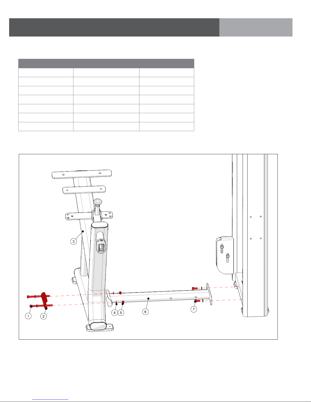
PART 1: STACK & USER FRAME ASSEMBLY
5
6
7
4
2
1
3
STEP 1 | WEIGHT STACK TO USER FRAME INSTRUCTIONS & NOTES
ID DESCRIPTION QUANTITY
1 M10 X 125L SHC 2
2 Wide Cupped Flange 1
3 User Frame 1
4 M10 Flat Washer 6
5 M10 Nylock Nut 2
6 Lower Connecting Tube 1
7 M10 X 20L SHC 2
Install the user frame hardware as shown, but DO NOT FULLY TIGHTEN .
ASSEMBLY
10
Page 11

ASSEMBLY
4
7
8
5
2
1
PART 1: STACK & USER FRAME ASSEMBLY
STEP 2 | WEIGHT STACK TO USER FRAME ASSEMBLY INSTRUCTIONS & NOTES
ID DESCRIPTION QUANTITY
1 M10 X 125L SHC 2
2 Wide Cupped Flange 2
4 M10 Flat Washer 8
5 M10 Nylock Nut 2
7 M10 X 20L SHC 4
8 Rear Connecting Tube 1
Install the user frame hardware as shown, but DO NOT FULLY TIGHTEN .
11
Page 12

PART 1: STACK & USER FRAME ASSEMBLY
12
11
10
9
STEP 3 | WEIGHT STACK TO USER FRAME INSTRUCTIONS & NOTES
ID DESCRIPTION QUANTITY
7 M10 X 20L SHC 4
9 Rear Stack Support 1
10 M10 Flat Washer (Small Diamter) 4
11 M8 X 20L SHC 2
12 M8 Flat Washer 2
ASSEMBLY
7
Install the user frame hardware as shown.
Torque M10 hardware to: 77 N-m/57 ft-lbs.
Torque M8 hardware to: 39 N-m/29 ft-lbs.
12
Page 13

4
5
15
14
13
ASSEMBLY
PART 1: STACK & USER FRAME ASSEMBLY
STEP 4 | WEIGHT STACK TO USER FRAME ASSEMBLY INSTRUCTIONS & NOTES
ID DESCRIPTION QUANTITY
4 M10 Flat Washer 4
5 M10 Nylock Nut 2
13 CAM Support Tube 1
14 M10 X 105 SHC 2
15 Narrow Cupped Flange 1
Torque all M10 hardware from pages 10, 11 & 13 to: 77N-m/57 ft-lbs.
Install the user frame hardware as shown.
13
Page 14

ASSEMBLY
7
4
16517
PART 1: STACK & USER FRAME ASSEMBLY
STEP 5 | WEIGHT STACK TO USER FRAME ASSEMBLY INSTRUCTIONS & NOTES
ID DESCRIPTION QUANTITY
4 M10 Flat Washer 5
5 M10 Nylock Nut 1
7 M10 X 20L SHC 3
16 M10 X 120L SHC 1
17 Upper Connecting Tube 1
Install the user frame hardware as shown, but DO NOT FULLY TIGHTEN .
14
Page 15

STEP 1 | EXERCISE ARM ASSEMBLY INSTRUCTIONS & NOTES
18
19
20
7
ID DESCRIPTION QUANTITY
7 M10 X 20L SHC 1
18 Exercise Arm 1
ASSEMBLY
PART 2: EXERCISE ARM ASSEMBLY
19
20 Orange Pivot Indicator 1
M10 Washer (Ø42 mm OD)
1
Torque item 7 to: 77 N-m/57 ft-lbs.
Install hardware as shown.
15
Page 16

STEP 2 | EXERCISE ARM ASSEMBLY INSTRUCTIONS & NOTES
4
21
22
5
23
ID DESCRIPTION QUANTITY
4 M10 Flat Washer 2
5 M10 Nylock Nut 1
21 M10 X 100L SHC 1
22 Axle 1
23 Ankle Pad and Weldment 1
ASSEMBLY
PART 3: EXERCISE ARM ASSEMBLY
16
Install hardware as shown.
Tighten to: 77 N-m/57 ft-lbs.
Page 17

STEP 1 | CABLE ASSEMBLY INSTRUCTIONS & NOTES
ASSEMBLY
PART 3: CABLE ASSEMBLY
Cable tension is adjusted by raising or lowering pulley as shown in View A.
Note: Nuts for adjustable pulley must be on inside towards weight plates.
VIEW A
17
Page 18

STEP 1 | HANDLEBAR ASSEMBLY INSTRUCTIONS & NOTES
25
24
4
5
ID DESCRIPTION QUANTITY
4 M10 Flat Washer 8
5 M10 Nylock Nut 4
24 Handlebar Assembly 1
25 M10 X 30L SHC 4
ASSEMBLY
PART 4: PAD ASSEMBLY
18
Install handlebars as shown.
Tighten to 77 N-m/57 ft-lbs.
Page 19

STEP 2 | PAD ASSEMBLY INSTRUCTIONS & NOTES
28
4
27
26
ID DESCRIPTION QUANTITY
4 M10 Flat Washer 6
26 M10 X 25L SHC 6
27 Thigh Pad 1
28 Pad 1
ASSEMBLY
PART 4: PAD ASSEMBLY
Install the pad as shown.
Tighten to 57 N-m/41 ft-lbs.
19
Page 20

STEP 3 | BACK PAD ASSEMBLY INSTRUCTIONS & NOTES
4
33
32
4
29
30
31
ID DESCRIPTION QUANTITY
4 M10 Flat Washer 4
29 Back Pad 1
30 Back Pad Mounting Tube 1
31 M10 X 75L SHC 2
32 M10 X 80L SHC 2
33 Back Pad Adjustment Tube 1
ASSEMBLY
PART 4: PAD ASSEMBLY
1. Assemble Back Pad to Mounting Tube, Torque hardware to 57
N-m/41 ft-lbs.
20
2. Assemble Back Pad assembly to
Adjustment Tube, Torque hardware to 57 N-m/41 ft-lbs.
Page 21

STEP 4 | BACK PAD ASSEMBLY INSTRUCTIONS & NOTES
ASSEMBLY
PART 4: PAD ASSEMBLY
3. Remove Limit Pin.
4. Raise Pull Pin to assemble entire
Back Pad assembly.
3
4
5. Re-assemble Limit Pin.
5
21
Page 22

STEP 1 | SHROUD ASSEMBLY ASSEMBLY INSTRUCTIONS & NOTES
34
ID DESCRIPTION QUANTITY
34 Front Shroud 1
35 Rear Shroud (Not shown) 1
Position hangers in their lowest position
ASSEMBLY
PART 5: PLASTICS ASSEMBLY
22
Install the weight stack shrouds as shown.
Page 23

STEP 2 | TOP CAP ASSEMBLY INSTRUCTIONS & NOTES
36
12
37
ID DESCRIPTION QUANTITY
12 M8 X 25L SHC 4
36 M8 Flat Washer (20 mm diameter) 4
37 Top Cap 1
ASSEMBLY
PART 5: PLASTICS ASSEMBLY
Install the top cap onto the weight stack as shown.
Position top cap so that the instructional placard faces the user.
Torque to 17 N-m/147 in-lbs.
23
Page 24

STEP 3 | TOP CAP COVERS INSTRUCTIONS & NOTES
38
38
ID DESCRIPTION QUANTITY
38 Top Cap Cover 2
ASSEMBLY
PART 5: PLASTICS ASSEMBLY
24
Install the top cap covers.
Page 25

OPTIONAL PREMIUM KIT ASSEMBLY INSTRUCTIONS & NOTES
3
1
6
5
2
4
ID DESCRIPTION QUANTITY
1P Wing 1
2P Rep Counter 1
3P Towel Hook 1
4P Premium Pullpin 2
5P ASG Pull Grip 2
ASSEMBLY
PART 6: PREMIUM KIT ASSEMBLY
1P
4P
5P
2P
3P
IMPORTANT NOTICE
PLEASE NOTE:
Be sure to remove the insulating
sheet when installing the
Rep Counter.
25
Page 26

STEP 1 | PREMIUM KIT ASSEMBLY INSTRUCTIONS & NOTES
Rep Counter - Magnet
1. Remove the (2) top cap covers using a flat blade
screw driver.
2. Remove the (4) M8 bolts and 20 mm diameter
washers that hold the top cap to the weight stack
frame.
Top cap covers, 20 mm diameter washers
& M8 screws can be discarded
ASSEMBLY
PART 6: PREMIUM KIT ASSEMBLY
3. Remove top cap and rear shroud.
4. Assemble the Repetition Counter magnet holder
to the headplate using the M5 X 12L bolt and M5
washer provided with the kit.
Holder must be mounted on thes same
side of the weight stack as Rep Counter
26
Page 27

STEP 2 | PREMIUM KIT ASSEMBLY INSTRUCTIONS & NOTES
Rep Counter - Sensors
1. Assemble Rep Counter sensor base using
(4) screws included with the kit.
2. Assemble (3) sensors located per machine chart shown below.
Thread zip ties through
holes to secure cables
Route wires in groove
ASSEMBLY
PART 6: PREMIUM KIT ASSEMBLY
Machine Sensor Locations (Sensor “A” = Top, “B” = Middle, “C” = Bottom)
Chest Press A2, B7, C13
Shoulder Press A1, B4, C13
Leg Extension A1, B7, C13
Seated Leg Curl A6, B10, C13
Leg Press A6, B10, C13
Lat Pulldown A1, B3, C13
Triceps Press A5, B8, C13
Seated Row A1, B4, C13
Bicep Curl A6, B8, C13
Hip Add/Abduction A7, B11, C13
Pec Fly/Rear Delt A7,B 9, C13
Abdominal A8, B10, C13
Back Extension A6, B8, C13
Glute A2, B7, C13
27
Page 28

STEP 3 | PREMIUM KIT ASSEMBLY INSTRUCTIONS & NOTES
Rep Counter
1. Remove and discard hole caps using caution
not to scratch the paint.
ASSEMBLY
PART 6: PREMIUM KIT ASSEMBLY
2. Attach plug to Rep Counter.
3. Assemble Towel Hook (3P) and Rep Counter
(2P) using the M8 X 35L SHC bolts provided.
Rep Counter wires must be routed
through the center of the Towel Hook
4. Torque bolts to 17 N-m/147 in-lbs.
28
Page 29

STEP 4 | PREMIUM KIT ASSEMBLY INSTRUCTIONS & NOTES
Wing
Assemble the wing (1P) as shown using the M8
hardware provided with the kit. Tighten to 39N-m
(29 ft-lbs.).
ASSEMBLY
PART 6: PREMIUM KIT ASSEMBLY
29
Page 30

STEP 5 | PREMIUM KIT ASSEMBLY INSTRUCTIONS & NOTES
Pull Pin
ASSEMBLY
PART 6: PREMIUM KIT ASSEMBLY
Remove the two pull pins using an adjustable wrench, and replace with the Premium pull pins
30
making sure that the pull pin lengths are correct for each application. (4P).
Page 31

STEP 6 | PREMIUM KIT ASSEMBLY INSTRUCTIONS & NOTES
ASG Grips
1,2,3
4
ASSEMBLY
PART 6: PREMIUM KIT ASSEMBLY
1. Remove the end caps using a 3 mm Allen wrench.
2. Cut off and discard the grips.
3. Remove inner collars with a 3 mm allen wrench.
4. Assemble the ASG grip (4P) as shown; lock inner
collars using a 4 mm Allen wench (torque to 8
N-m/5 ft-lbs.), and a 3 mm Allen wrench to secure
the end caps.
5. Orient ASG grips as shown, with thumb index
angled in for comfort.
5
31
Page 32

Matrix Fitness
1600 Landmark Drive
Cottage Grove WI 53527
matrixfitness.com
Toll-free 866.693.4863
Facsimilie 608.839.8687
Versa Leg Extension Owners Guide Rev.1.2 Copyright © 2013 Matrix Fitness
 Loading...