

Matrix Vision, EPABX Vision-206S, EPABX Vision-207P, EPABX Vision-308S, EPABX Vision-309P User Manual
Page 1

VISION
Magyarországon a Matrix Telecom Ltd. képviselete,
Matrix termékek importőre, kizárólagos forgalmazója:
1095 Budapest, Mester u. 34.
Telefon: *218-5542, 215-9771, 215-7550, 216-7017, 216-7018
Fax: 218-5542 Mobil: 30 940-1970, 20 949-2688
E-mail: delton@delton.hu Web: www.delton.hu
System Manual
Page 2

Documentation Information
This is a general documentation and it covers many models with different specifications. A particular product
may not support all the features and facilities described in the documentation.
Matrix Telecom reserves the right to revise information in this publication for any reason without prior notice.
Information in this documentation may change from time to time. Matrix Telecom makes no warranties with
respect to this documentation and disclaims any implied warranties. While every precaution has been taken in
preparation of this system manual, Matrix Telecom assumes no responsibility for errors or omissions. Neither is
any liability assumed for damages resulting from the use of the information contained herein.
Matrix Telecom reserves the right without prior notice to make changes in design or components of the
equipment as engineering and manufacturing may warrant.
Neither Matrix Telecom nor its affiliates shall be liable to the purchaser of this product or third parties for
damages, losses, costs or expenses incurred by purchaser or third parties as a result of: accident, misuse or
abuse of this product or unauthorized modifications, repairs or alterations to this product or failure to strictly
comply with Matrix Telecom’s operating and maintenance instructions.
All rights reserved. No part of this system manual may be copied or reproduced in any form or by any means
without the prior written consent of Matrix Telecom.
Page 3

Contents
Section 1: Introduction................................................................................................................................. 5
Welcome............................................................................................................................................................7
Packing List ....................................................................................................................................................... 8
Warranty Statement .......................................................................................................................................... 9
Introducing the System ................................................................................................................................... 11
Protecting the System .....................................................................................................................................15
Installing the System ....................................................................................................................................... 17
Getting Started ................................................................................................................................................ 20
Section 2: Features and Facilities............................................................................................................. 23
Abbreviated Dialing ......................................................................................................................................... 25
Alarms.............................................................................................................................................................. 28
Allowed and Denied Lists ................................................................................................................................ 31
Alternate Number Dialing ................................................................................................................................ 35
Auto Call Back (ACB) ...................................................................................................................................... 38
Auto Redial ...................................................................................................................................................... 40
Barge-In........................................................................................................................................................... 44
Behind the PBX Applications...........................................................................................................................45
Boss Ring ........................................................................................................................................................ 47
Call Duration Control (CDC) ........................................................................................................................... 48
Call Forward .................................................................................................................................................... 53
Call Park .......................................................................................................................................................... 56
Call Pick Up ..................................................................................................................................................... 57
Call Progress Tones........................................................................................................................................ 58
Call Splitting.....................................................................................................................................................61
Call Transfer .................................................................................................................................................... 63
Calling Line Identification and Presentation (CLIP) ....................................................................................... 65
Cancel Station Features ................................................................................................................................. 69
Class of Service (COS) ................................................................................................................................... 70
Communication Port ........................................................................................................................................ 75
Conference......................................................................................................................................................77
Configuration Reports ..................................................................................................................................... 80
Continued Dialing ............................................................................................................................................ 88
Department Call ............................................................................................................................................... 89
Dial by Name ...................................................................................................................................................91
Direct Inward Dialing (DID) ............................................................................................................................. 94
Direct Outward System Access (DOSA)........................................................................................................100
Distinctive Rings ............................................................................................................................................104
Door Phone ................................................................................................................................................... 105
Dynamic Lock ................................................................................................................................................ 107
External Call................................................................................................................................................... 109
External Call Forward (ECF) ......................................................................................................................... 110
External Music ............................................................................................................................................... 112
Flash Timer .................................................................................................................................................... 1 13
Flexible Numbers........................................................................................................................................... 114
Hold ............................................................................................................................................................... 116
Hotline............................................................................................................................................................ 117
Internal Call ................................................................................................................................................... 119
Internet Ready Port.......................................................................................................................................120
Interrupt Request ..........................................................................................................................................122
Page 4

Last Number Redial....................................................................................................................................... 123
Least Cost Routing (LCR).............................................................................................................................124
Live Call Supervision ..................................................................................................................................... 132
Music-on-Hold (MOH) ................................................................................................................................... 133
Operator ........................................................................................................................................................ 135
Paging............................................................................................................................................................ 136
Power Down Mode ........................................................................................................................................ 138
Privacy ...........................................................................................................................................................139
Programming the System .............................................................................................................................. 143
Raid ............................................................................................................................................................... 146
Real Time Clock (RTC) ................................................................................................................................. 147
Relay Port......................................................................................................................................................148
Remote Programming.................................................................................................................................... 154
Scheduled Dialing ......................................................................................................................................... 156
Security Dialer ............................................................................................................................................... 158
Selective Trunk Access ................................................................................................................................. 162
Station Group ................................................................................................................................................163
Station Message Detail Recording (SMDR) .................................................................................................168
Station Parameters ........................................................................................................................................ 177
System Parameters .......................................................................................................................................179
System Security (Passwords)........................................................................................................................ 180
Time Table.....................................................................................................................................................181
Toll Control .................................................................................................................................................... 184
Trunk Access Groups.................................................................................................................................... 189
Trunk Landing Groups .................................................................................................................................. 196
Trunk Parameters .........................................................................................................................................199
Trunk Reservation.........................................................................................................................................203
User Security (User Password).....................................................................................................................204
Voice Message Applications..........................................................................................................................205
Walk-in Class of Service ............................................................................................................................... 211
Section 3: Appendices.............................................................................................................................. 213
Appendix A: Technical Specifications............................................................................................................ 215
Appendix B: Feature Commands ..................................................................................................................216
Appendix C: Programming Commands .........................................................................................................219
Appendix D: Troubleshooting ........................................................................................................................ 225
Glossary ........................................................................................................................................................ 227
Index.............................................................................................................................................................. 228
Notes ............................................................................................................................................................. 232
Programming Register ................................................................................................................................234
Page 5

Section 1: Introduction
Page 6

Page 7

Matrix
Welcome
Welcome to the world of telecom solutions from Matrix and thanks for purchasing a Matrix product.
We want you to get the maximum performance from our product. If you run into technical difficulties, we are
here to help. But please consult this system manual first.
If you still can’t find the answer, gather all the information or questions that apply to your problem and, with the
product close to you, call your dealer. Matrix dealers are trained and ready to give you the support you need to
get the most from your Matrix product. In fact, most problems reported are minor and can be easily solved over
the phone.
In addition, technical consultation is available from Matrix engineers every business day. We are always ready
to give advice on application requirements or specific information on installation and operation of our products.
The system manual is divided in following sections:
Section 1: Introduction
Section 2: Features and Facilities
Section 3: Appendices
We suggest the first time users to read this system manual in the following sequence.
• Section 1
• Section 2 (in the given below hierarchy)
• Introducing the System 11
• Installing the System 17
• Protecting the System 15
• Internal Call 119
• External Call 109
• Music on Hold 133
• Hold 116
• Call Transfer 63
• Call Pick Up 57
• Call Forward 53
• Call Splitting 61
• Auto Call Back 38
• Last Number Redial 123
• Auto Redial 40
• Alternate Number Dialing 35
• Call Park 56
• Interrupt Request 122
• Barge-In 44
• User Security (Password) 204
• Programming the System 143
The user can use the pages named ‘Notes’ given at the end of the system manual for making note of
customer’s requirements and ‘Programming Register’ for registering the programming changes
Datewise. These could be used for future reference.
Vision System Manual
7
Page 8

Matrix
)
Packing List
The ideal sales package for Vision is as mentioned below:
EPABX Vision-206S/207P/30 8S/309P
Sr. Item Qty.
01 EPABX Vision 1
02 System Manual 1
03 User's Guide 1
04 Vision Quick Start 2
05 Vision Programming Card 1
06 Fuse FB 2.5 Amp. 1
07 Fuse FB 3.5 Amp. 1
08 Battery Cable 1
09 T. P. G. 1
10 Screw Grip 2
11 Screw M 7 X 30 2
12 Warranty Card Set 1
13 Support Card 1
14 Matrix Logo Small 5
15 Telephone Message Pad 1
16 Label Factory Seal 1
17 Mounting Template 1
Ducumentation CD (System Manual, User's
18
Guide and Quick Start
1
• Please make sure that these components are present.
• In case of short supply or damage detection, contact the source for where you have purchased the system.
=X=X=
8
Vision System Manual
Page 9

Matrix
Warranty Statement
Matrix warrants to its consumer purchaser any of its products to be free of defects in material, workmanship and
performance for a period of 15 months from date of manufacturing or 12 months from the date of installation
which ever is earlier.
During this warranty period, Matrix will at its option, repair or replace the product at no additional charge if the
product is found to have manufacturing defect. Any replacement product or part/s may be furnished on an
exchange basis, which shall be new or like-new, provided that it has functionality at least equal to that of the
product, being replaced. All replacement parts and products will be the property of Matrix. Parts repaired or
replaced will be under warranty throughout the remainder of the original warranty period only.
This limited warranty does not apply to:
1. Products that have been subjected to abuse, accident, natural disaster, misuse, modification, tampering,
faulty installation, lack of reasonable care, repair or service in any way that is not contemplated in the
documentation for the product or if the model or serial number has been altered, tampered with, defaced or
removed.
2. Products which have been damaged by lightning storms, water or power surges or which have been
neglected, altered, used for a purpose other than the one for which they were manufactured, repaired by
customer or any party without Matrix’s written authorization or used in any manner inconsistent with Matrix’s
instructions.
3. Products received improperly packed or physically damaged.
4. Products damaged due to operation of product outside the products’ specifications or use without designated
protections.
Warranty valid only if:
• Primary protection on all the ports provided.
• Mains supply is within limit and protected.
• Environment conditions are maintained as per the product specifications.
Warranty Card:
• When the product is installed, please return the warranty card with:
• Date, signature and stamp of the customer.
• Date, signature and stamp of the channel partner.
• Matrix assumes that the customer agrees with the warranty terms even when the warranty card is not signed
and returned as suggested.
The Purchaser shall have to bear shipping charges for sending product to Matrix for testing/rectification. The
product shall be shipped to the Purchaser at no-charge if the material is found to be under warranty. The
Purchaser shall have to either insure the product or assume liability for loss or damage during transit.
Matrix reserves the right to waive off or make any changes in its warranty policy without giving any notice.
If Matrix is unable to repair or replace, as applicable, a defective product which is covered by Matrix warranty,
Matrix shall, within a reasonable time after being notified of the defect, refund the purchase price of the product
provided the consumer/purchaser returns the product to Matrix.
In no event will Matrix be liable for any damages including lost profits, lost business, lost savings, downtime or
delay, labor, repair or material cost, injury to person, property or other incidental or consequential damages
arising out of use of or inability to use such product, even if Matrix has been advised of the possibility of such
damages or losses or for any claim by any other party.
Vision System Manual
9
Page 10

Matrix
Except for the obligations specifically set forth in this Warranty Policy Statement, in no event shall Matrix be
liable for any direct, indirect, special, incidental or consequential damages whether based on contract or any
other legal theory and where advised of the possibility of such damages.
Neither Matrix nor any of its distributors, dealers or sub-dealers makes any other warranty of any kind, whether
expressed or implied, with respect to Matrix products. Matrix and its distributors, dealers or sub-dealers
specifically disclaim the implied warranties of merchantability and fitness for a particular purpose.
This warranty is not transferable and applies only to the original consumer purchaser of the Product. Warranty
shall be void if the warranty card is not completed and registered with Matrix within 30 days of installation.
=X=X=
10
Vision System Manual
Page 11

Matrix
Introducing the System
The Vision is a versatile PBX system specifically designed for small offices, banks, Schools, big departmental
stores, hospitals and other such places. The Vision is shown in the figure given below:
Vision System Manual
11
Page 12
Matrix
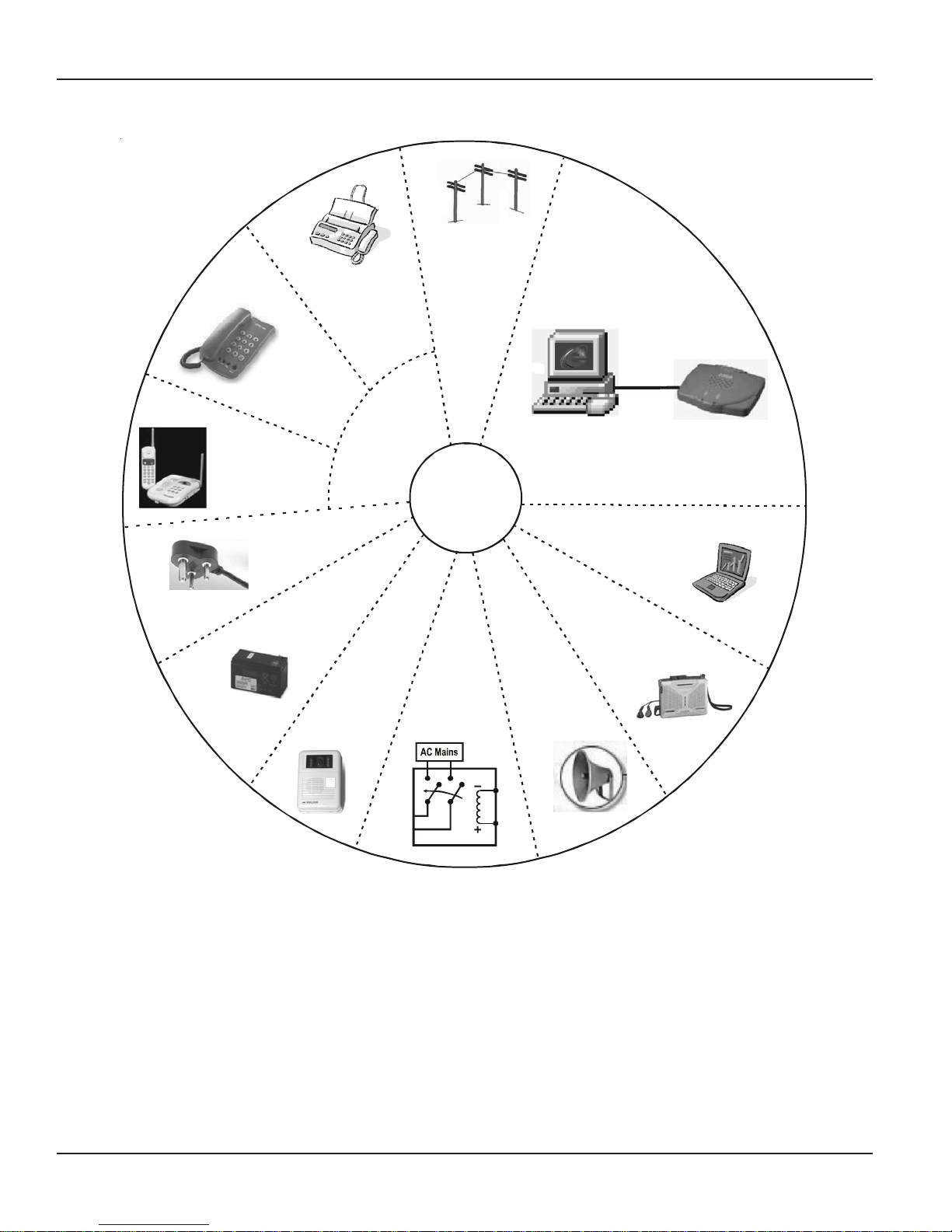
The Vision offers a number of extra interfaces as shown below:
Analog
Trunk
Fax
Conventional
Telephone
Instrument
Station
Cordless
Telephone
Instrument
Vision
Computer
Modem
Internet Ready Port
230V A C
Battery
Door Phone
The Vision series from Matrix offers four models viz.
• Vision-206 Standard.
• Vision-206 Premium.
• Vision-308 Standard.
• Vision-308 Premium.
Relay
Computer
Music Source
PAS
Features of Vision-206 Standard and Vision-308 Standard:
• Efficient Power Supply based on Switched Mode Power Supply Scheme.
• Wide Input Voltage Range- 90-265VAC, 47-63Hz.
• Built-In Battery Charger.
• Internet Ready Port.
• Supports On-site programming as well as Remote programming.
12
Vision System Manual
Page 13

• Compatible with any type of telephone instrument.
• Supports basic features like:
• Alarms
• Auto Call Back
• Barge-in
• Internal Dialing
• Hold/Toggle
• Call Forward
• Call Park
• Call Pick Up
• Call Transfer
• Class of Service
• Distinctive Rings
• Executive-Secretary (Hotline)
• Flexible Numbers
• Hotline
• Hunting Schemes
• Interrupt Request
• Last Number Redial
• Music on hold
• On site programming
• Power Down Stations
• Programmable Feature Access
• Programmable Access to Programming of System
• Pulse and DTMF dialing
Matrix
• It also supports advanced features like:
• Abbreviated Dialing
• Alternate Number Dialing
• Automatic Call Disconnector
• Auto Day/Night Mode
• Auto Redial
• Auto Shut dynamic Lock
• Boss Ring
• Call Privacy
• CLIP (Caller Line Identification and Presentation)
• CLI based ECF
• CLI based Routing
• Conference
• DID
• DOSA
• External Call Forwarding
• Flashing on Trunk
• Group Call
• Least Cost Routing
• Live Call Supervision
• Programmable Timers
• Programmable Trunk Access
• Raid
• Schedule Dialing
• Selective Trunk Access
• Toll Control
Vision System Manual
13
Page 14

Matrix
• Trunk Groups
• Walk-in Class of Service
More advanced features available in Vision-206 Premium and Vision-308 Premium:
• Auto-Attendant
• Computer Connectivity
• Dial by Name
• Digital Input Port
• Door Lock
• Door Phone
• External Music Port
• Inbound Call Analysis
• PAS Port
• Relay Port
• Security Dialer
• SMDR
• Voice Guidance
=X=X=
14
Vision System Manual
Page 15

Matrix
Protecting the System
The Vision does not work in isolation with the environment. It is connected to the environment in following ways.
• Power is fed to the system for functioning of the system.
• Being a PBX system, trunk lines and stations are also connected to the system.
• System also has other interfaces like External Music, PAS, DIP, Computer, Relay Port. Hence there are
chances that heavy voltages can enter the system through these interfaces.
• The system should be protected from static charges that could find their way through the system
components.
If the system is protected from these interfaces, 100% satisfactory and trouble free performance of the system
is guaranteed.
Protecting the System from heavy voltages from the mains:
The Vision is designed to work with input voltages ranging between 90 to 265VAC, 47-65Hz. The Power Supply
of Vision is designed on switch mode design and hence support such a wider range of operating voltage.
However to protect the system from abrupt changes in the input voltage, use of CVT is recommended. CVT of
100VA or 150VA is recommended.
Protecting the System from heavy voltages on the trunk lines and the overhead stations:
The Vision can get damaged if heavy voltages enter the system from trunk lines or from overhead stations.
These heavy voltages could be due to:
• Heavy voltage line falling on the CO line or on the overhead stations cable
• Thunderbolts
• Short-circuit of trunk lines or overhead station cables with electric cables
It is necessary to protect the Vision from these voltages. The protection can be in the form of some protection
devices like GDTs, MOVs, Fuses, etc. These protection devices are inbuilt for each trunk in the system.
These devices work satisfactorily only if they are properly earthed. It is recommended that Vision is provided a
separate telecom earth. A dedicated terminal marked ‘ETH’ is provided on the MDF of the system to which the
telecom earth should be connected. Telecom earth is a dedicated earth only for the PBX. The advantage of
having a dedicated earth is that there is no risk of back voltage. There are chances that if the earth is not
perfect, instead of providing protection to the system, it may damage the system.
Protecting the System from static charges:
While installing the system or servicing the system, care must be taken to provide a path to the static charges.
It is advisable for the system engineer to touch a grounded object before touching the system before
installation or maintenance.
Protecting the System from heavy voltage on the communication cable:
The Vision provides a communication port to which a computer can be connected. It is recommended to run the
cable connecting both the devices through the conduit carrying telephone cables or through a separate
conduit. By fluke if an electrical wire carrying heavy voltage shorts with this cable, heavy voltages can damage
the communication port.
Protecting the System from heavy voltage on the External music port:
The external music port of the Vision should be protected from:
• Heavy voltages on the cable connecting the Vision and the external music source due to shorting with any
electrical wire.
• An audio signal, which is not as per the specifications, is fed to this port. Please refer ‘Music On Hold’ for
specifications.
Vision System Manual
15
Page 16
Matrix
Protecting the System from heavy voltage on the PAS port:
The PAS port of the Vision should be protected from:
• Heavy voltages on the cable connecting the Vision and the amplifier/speaker due to shorting with any
electrical wire.
• Faulty Amplifier
Protecting the System from heavy voltage on the DIP:
The DIP of the Vision should be protected from:
• Heavy voltages on the cable connecting the Vision and the panic switch or the sensor.
• Faulty panic switch or the sensor.
Protecting the System from heavy voltage on the Relay Port:
The Relay port of the Vision should be protected from:
• Heavy voltages on the cable connecting Vision and the Equipment/Doorlock/Contactor connected to it.
• Faulty or overrated Contactor/Equipment/Doorlock.
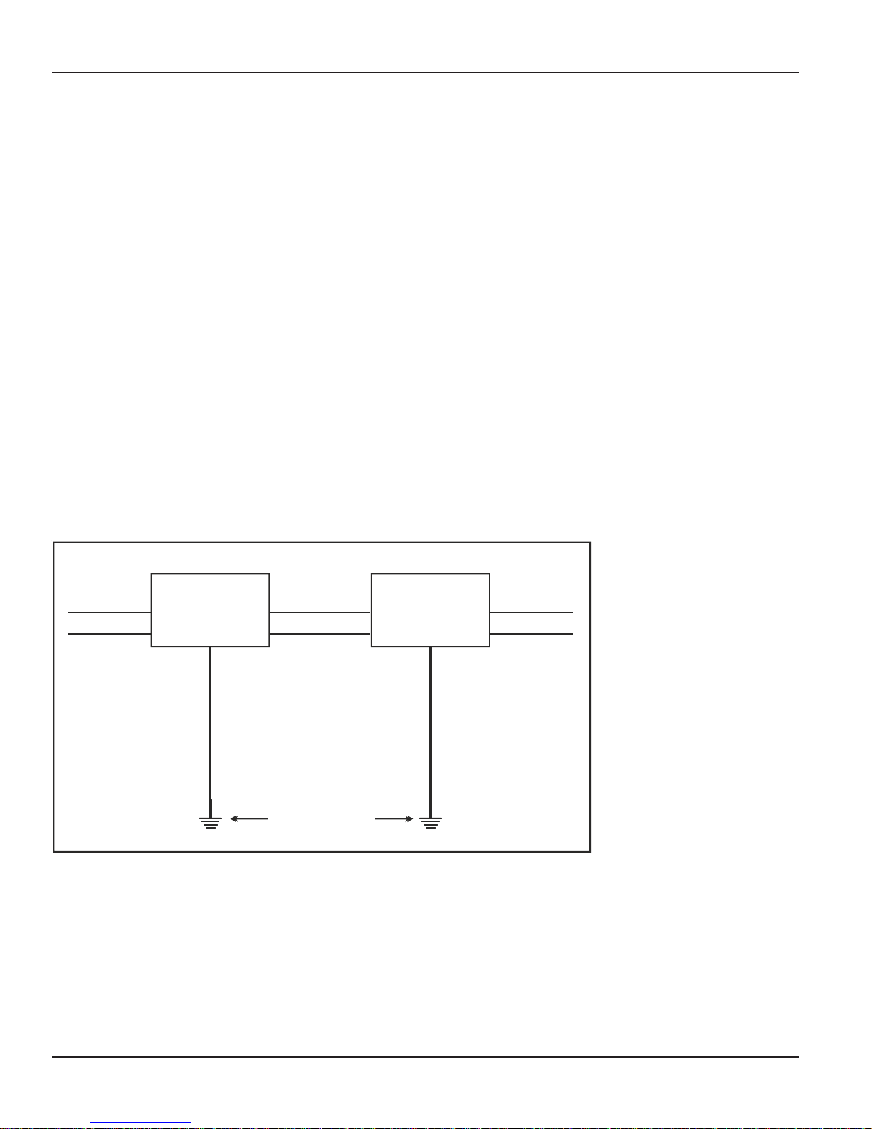
Protecting the System from Lighting:
Protecting the system from high current surges is achieved by installing primary protection device. A lightning
protector is a primary protection device which is used to prevent a dangerous surge from entering the building
and damaging the system. For equipment installed in a more exposed environment, it is necessary to protect
the system with primary protectors such as PPMs. With the development of electronic equipment, problems due
to lighting surges have increased. A dangerous surge can occur if a telephone line comes in contact with a
power line. A lightning protector should be installed on an outside (CO) line to prevent a dangerous surge from
entering the building and damaging the system. The best place for the insertion of the primary protection is the
cable entry point of the building, shelter or equipment housing.
CO Line
Lightning
Protectors
CO Line
System
Protective Earth
Terminal
Telecom Earth
This is not always possible but every attempt should be made to place the primary protection as close as
possible to the entry point of the cables into the building, shelter or equipment housing. Hence, the system
should be installed with lighting protectors. In addition, grounding (connection to earth ground) is very
important to protect the system.
=X=X=
16
Vision System Manual
Page 17

Matrix
Installing the System
Precautions:
Before installing the System, please read the following precautions carefully:
• Do not open the system in power-ON condition.
• Do not plug/unplug any card in power-ON condition. This may damage the system. Warranty does not cover
such damages.
• The Vision uses CMOS parts. These parts are sensitive to electro-static discharges. Observe anti static
rules strictly.
• Do not install this product near water, for example near a bathtub, washing bowl, kitchen sink, laundry tub,
swimming pool etc.
• Slots on enclosure are for proper ventilation. They will protect the system from overheating. Never cover the
slots.
• Never place this product on heated place or any other equipment.
• Never push objects of any kind inside this product. This may short-circuit various parts.
• Operate these products only with 90-265VAC, 47-63Hz supply and if you are not sure about supply voltage,
contact authorized dealer. It is advisable to give proper, stabilized power.
• This product is equipped with a plug having a third (ground) pin, which fits only into a grounding-type outlet.
This is a safety feature. If you are unable to insert the plug into the outlet, ask an electrician to replace the
obsolete outlet. Do not defeat the purpose of the grounding type plug.
• Unplug this product from electric wall outlet in following cases and contact authorized service personnel.
• Liquid spills on to the product.
• Product exposed to rain or water.
• Product does not operate normally by following operating instructions.
• Product dropped from height.
• Product exhibits unusual change in performance.
• Never do telephone wiring during a lightening storm.
• Avoid using telephone other than a cordless type during an electric storm. There may be a remote risk of
electric shock from lightening.
• Never use a telephone to report gas leaks if it is near to gas leak.
• Do not touch non-insulated telephone wires or terminals before disconnecting at the network interface.
• Please connect a Telecom earth to the system (to the port marked ‘ETH’ on the MDF).
• The protection device, GDT protects the system efficiently only if it is provided good telecom earth. Please
note that protection device protects the system, however they do not guarantee 100% protection from
lighting storm, induced voltages, etc. Please note that warranty does not cover such damages.
• Please note that these products are designed to work efficiently at temperature ranging from 0o C to 45o C
(32o to 113o Fahrenheit) with 95% relative humidity, non-condensing.
Site Selection
• The Vision should always be installed at a place equi-distant from all the stations. This reduces the cabling
cost and also makes cabling network less complicated.
• It should preferably be installed at 3.5 feet height (approx.) in airy, dust free and moisture free place. An
installation at this height makes preventive or curative maintenance task easy.
• It is advisable that the system should be installed away from any source of electromagnetic noise such as
any radio equipment, heavy transformers, faulty electric chokes of tube-lights, any device having a faulty coil
etc. This will reduce any problem arising due to electromagnetic effect.
Cabling
• Select a good quality telephone cable (with 0.5 mm conductor diameter) for internal cabling as well as for
over-head cabling.
• Ensure separate cable conduits for both electrical and telephone cables.
• Take care that cables are not left open on the ground where they may get damaged due to entanglement in
Vision System Manual
17
Page 18

Matrix
the foot or due to pressure from other heavy objects.
• Avoid long length cables and at the same time keep number of joints to a minimum i.e. strike a balance
between the two. This will help you to find out a cable fault easily.
Power Supply
• The Vision operates on 90-265VAC, 47-63Hz supply. Arrange for a separate power point and switch, close
to the system.
• Power Supply for the Vision must be separate from other heavy electrical loads like Air-conditioners, Heaters,
Welding machines, Electrical motors, heavy transformers, tube lights having faulty chokes, electric bell and
other such noise generating equipments.
• Please ensure that the system is properly earthed. For more details, please refer “
Protecting the System”.
Installation
• Unpack the box. Get satisfied with the contents and the condition of all the parts. In case of short supply or
damaged parts, please contact the source from where you purchased the system immediately.
• Please refer to the Mechanical Dimensions given at the end of this topic. To know the pitch of mounting
holes.
• Check the mains voltage at the power plug from where the supply is to be given to the system. It should be
as per the specifications. Earth the system properly.
• Connect 2 conventional telephone instruments directly at the MDF.
• Connect the power cord to the power plug. Ensure proper contacts. Switch ‘ON’ the system. Observe the
reset cycle on the front panel of the system.
• Reset Cycle: On power ON, all the LEDs on the front panel glow in a sequence. The system follow reset
cycle. Then after the system gives dial tone to all the stations.
• Check for dial tone on the telephone instruments connected to the system.
• Switch ‘OFF’ the system. Remove the power cord of the system from the power plug.
• Remove the telephone instruments connected to the system for testing purpose.
• Now connect all the trunk and station cables to the system.
• Ensure proper telecom earth on MDF for best protection.
• Tag each wire pair with respective Station/Trunk number. Different color tags for Trunk/Station can be used
for better identification.
• Now again power the system for final switch ON. Ensure proper contacts.
• To use other interfaces like Computer, External Music, Security Dialer and Public Address System (PAS),
please refer respective topics in this manual.
18
Vision System Manual
Page 19
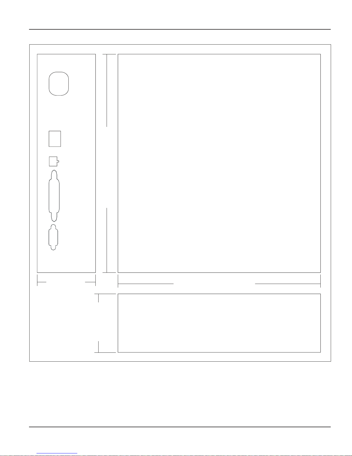
Vision Mechanical Drawing
Matrix
75.00 mm
(2.953 Inch)
75.00 mm
280.00 mm(11.024 Inch)
260.00 mm(10.236 Inch)
(2.953 Inch)
Vision System Manual
=X=X=
19
Page 20

Matrix
Getting Started
Switching ON the Vision
Switch on the system. The reset cycle can be seen on the front panels of all the cards of the system. Test the
system for proper functioning by making internal calls to other stations and by making trunk calls.
Stations
Standard telephones instruments like Rotary phone, Pulse-tone switchable push-button phone, Feature phone,
CLI display phone or a Cord-less phone can be connected to the Vision. Hence, it is not necessary to buy all
new phones. Existing, old but working telephones can also be used.
Trunk Lines
Analog trunk lines can be connected to the system. Please ensure telecom earth to the system.
How to make a perfect earth?
• Dig a pit of area 2 feet x 2 feet x 6 feet. (lxbxd). Please refer to the figure on the next page.
• Get a copper plate of size 1.5 feet x 1.5 feet x 0.25 feet.
• Connect a copper strip of size 1-inch wide, 3 mm thick and 6 feet length at the center of the copper plate by
welding or nuts and bolts.
• Insert a G.I pipe onto the copper strip till it reaches the copper plate.
• Place this set up into the pit and ensure that at least 4 inch of the G.I pipe is above the ground level.
• Fill the pit 1-inch layer of charcoal and salt in 3:1 ratio at the bottom and then with the soil.
• Connect a bare 14 SWG copper wire (double) on the top of the copper strip and run it to the exchange room
and connect it on the bus bar.
• Bus bar is a copper strip 4-inch long with 6 nos. of screws and nuts mounted on it. It has to be fixed on the
wall in the exchange room.
• The earth wire of the system should be connected to this bus bar.
• It is recommended to water the earth at regular intervals.
Testing the Installation.
• In the Power ON mode the system is ready for use with predefined values for variables like extension’s
flexible numbers, timers and other programmable parameters.
• It is required to check the functioning of the system by testing all the extensions and the trunk.
• Test all extensions for dial tone, ring back tone, speech and ring one by one.
• Test functioning of the trunk by dialing outside number from one of the extensions and checking the trunk
tones and speech. Ring on the trunk can be tested by asking your friend to dial your number.
How to make an Internal Call?
• Lift the handset.
• Dial the desired extension’s flexible number.
• The called extension rings. You get a Ring Back Tone.
• Speech is established when the called party lifts the handset.
Important Points:
• Hands free Operation is also possible if a speakerphone is used.
• The extensions having access to internal call will only be able to make Internal Calls.
How to make External Call?
• Lift the handset.
• Dial trunk access code
• Dial the external Telephone Number.
20
Vision System Manual
Page 21

Matrix
Important Point:
• The extensions having access to trunk and higher Toll control will only be able to make External Calls.
Answering Calls
When a call is placed to your extension ,if the caller is an internal caller then your extension rings as
Trin....Trin...............Trin.....Trin............... This is called double ring. If the caller is an external caller, the
extension on which the trunk call lands rings as Trin................ Trin.................... This is single ring. These two
types of rings differentiate an internal caller from an external caller.
Programming the System
Many a times it happens that the default settings do not meet our requirements and there is need to program
the system. Programming is possible only from System Engineer/System Administrator mode. For more details
Please refer ‘
Programming the System’.
=X=X=
Vision System Manual
21
Page 22

Page 23

Section 2: Features and Facilities
Page 24

Page 25
Matrix
Abbreviated Dialing
What’s this?
• Frequently called numbers can be stored in the system. These numbers can be dialed using specific codes.
This is called Abbreviated dialing. It is also known as Memory Dialing.
• This helps save time while dialing such frequently used numbers.
• An abbreviated number is dialed through its directory index.
The Vision offers two types of abbreviated dialing:
• Personal Abbreviated Dialing.
• Global Abbreviated Dialing.
Personal Abbreviated Dialing
• Each user is allocated memory space called personal memory to store 10 numbers of his own choice. This is
called Personal Abbreviated Dialing. These numbers are dialed out using access codes 800-809.
• The numbers stored in the personal memory of a user are dialed out.
• Each user can store up to 10 numbers of his choice in his personal memory.
• User can change these numbers anytime from his station without consulting the System Administrator or the
System Engineer.
• The location codes for Personal Abbreviated Dialing are 00-09. Hence the access codes are 800 to 809.
• Personal Abbreviated Dialing is allowed to all the users.
• The system checks Trunk Access Group and Toll Control allowed list and denied list before dialing the
Personal Abbreviated number. Hence for Personal Abbreviated Dialing, Trunk Access Group, Toll Control
allowed list and Toll Control denied list should be programmed properly.
• A printout of station parameters will show the telephone numbers programmed in the personal directory by
the station user.
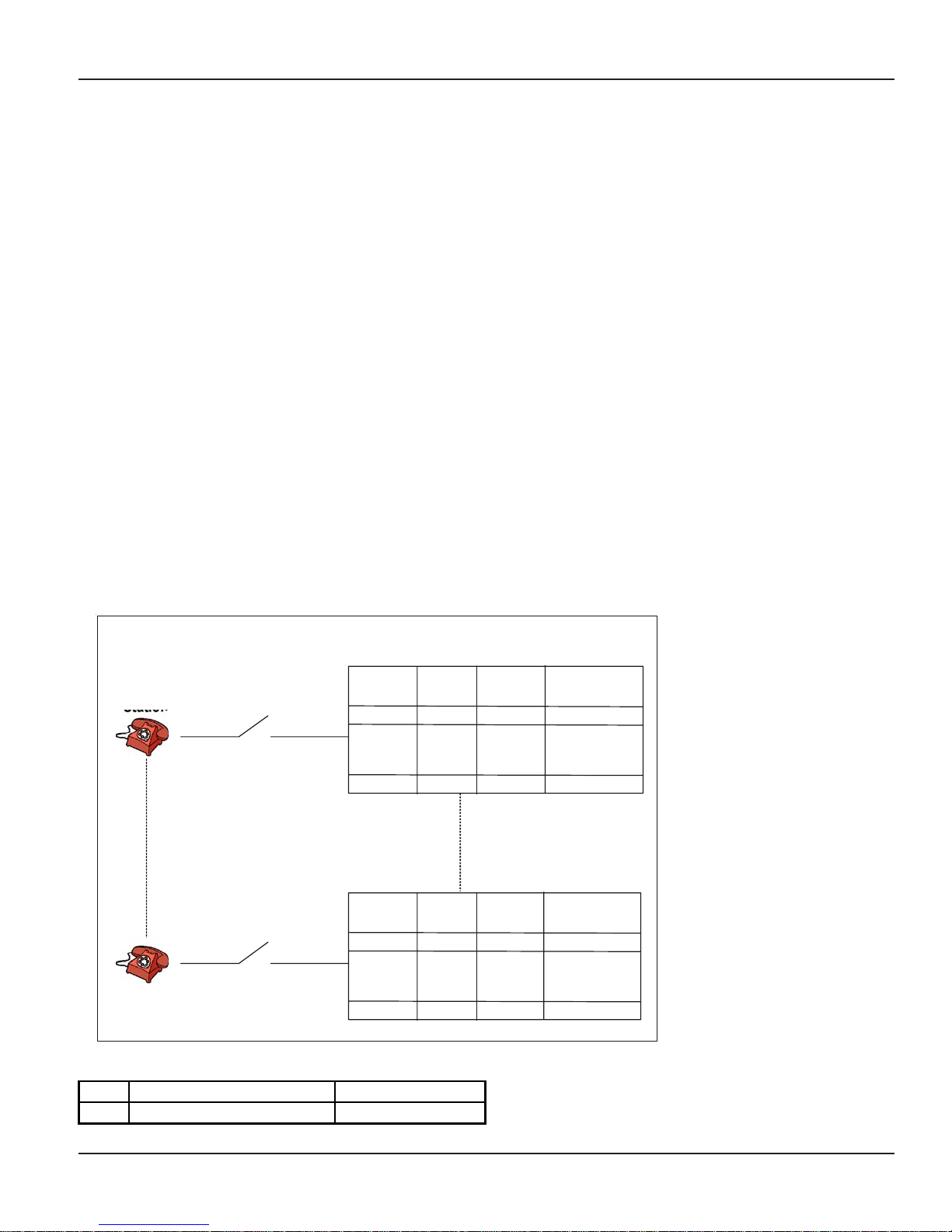
Personal Abbreviated Dialing
Directory
Station
21
29
Toll Control
Trunk Access Group
Toll Control
Trunk Access Group
How to use Personal Abbreviated Dialing?
1 Lift the handset. Dial tone
Dial
2
8-Directory Index.
Index
00
:
:
09
Directory
Index
00
:
:
09
Number dialed out.
Trunk Number
Trunk Number
Name
0
Tanima
:
:
7
Bharti
Name
1
Vijay
:
:
5
Amit
:
:
:
:
952666269156
:
:
02612266266
02612446266
:
:
02228956212
Vision System Manual
25
Page 26

Matrix
How to program Personal Abbreviated Dialing?
1 Lift the handset. Dial tone
Dial
2
3 Replace the handset.
In the above command
Location code is from 00 to 09.
Trunk Access Code is 0, 5, 61, 62.
Number is the telephone number, which is to be abbreviated.
Example:
To program telephone number 0265-2630555 at directory index 00 with trunk access code ‘62’, dial
18-00-62-02652630555.
Once this location is programmed with the number, dial 800 to call the number.
Global Abbreviated Dialing
• Besides personal memory, 90 numbers can be stored in a common memory space called global memory.
These numbers are dialed out using Access codes 810-899. This is called Global Abbreviated Memory.
• The numbers stored in the global memory of the system are dialed out.
• Global directory can be programmed either by the System Administrator or the System Engineer.
• The global directory is common for all the users.
• Maximum 90 numbers can be stored in the global directory. Location codes for global directory are from 10
to 99. Hence the access codes for global abbreviated dialing are 810 to 899.
• Global Directory is divided into two parts i.e. Global Directory part 1 and Global Directory part 2.
• A user can dial these numbers irrespective of his Toll Control and Trunk Access Group. However these
numbers can be dialed only if the user is allowed this feature from Class of Service.
• Telephone numbers of fire, police, branch offices or such other places can be stored in global directory part
1 and its access be given to all the users so that any user can access this facility.
• Long distance numbers can be stored in global directory part 2 and its access be given to selected users.
• In case of long distance numbers, complete numbers with preceding codes should be entered.
18-Location Code-Trunk Access Code-Number-#*.
Confirmation tone
Global Abbreviated Dialing
How to use Global Abbreviated Dialing?
1 Lift the handset. Dial tone
Dial
2
8-Location Code.
Number dialed out.
26
Vision System Manual
Page 27

Matrix
Example: To program telephone number of police i.e. 100 at location code 10. Dial 1301-1-10-100#*. To call
Police station user has to dial 810.
How to program?
Step 1: Make a list of telephone numbers to be stored in global directory.
Step 2: Program the telephone numbers in appropriate part at various locations using command 1301.
Step 3: Clear the numbers from a various locations using command 1301 (if wrongly programmed).
Step 4: Set Trunk Access Group using command 1302.
Step 1
Take a piece of paper and a pen and make a list of telephone numbers.
Step 2
Use following command to program a telephone number in Global Directory list:
1301-1-Location Code-Number-#*
Where,
Location Code is from 10 to 99.
Global Directory part 1 is from 10 to 54.
Global Directory part 2 is from 55 to 99.
Number is the telephone number (maximum 16 digits).
Step 3
Use following command to clear a number in a particular global directory index:
1301-1-Location Code-#*
Where,
Location Code is from 10 to 99.
Use following command to clear the number in all the global directory indexes:
1301-*-#
Step 4
Use following command to set Trunk Access Group for particular location:
1302-1-Location Code-Trunk Access Group
Where,
Location Code is from 10 to 99.
Trunk Access Group is from 0 to 7.
Use following command to set same Trunk Access Group for all locations:
1302-*-Trunk Access Group
Important Points:
• To know programming details, please refer “Configuration Reports”.
• Pause can be entered while storing the telephone number if required. A code ‘#3’ can be used as Pause
digit. Suppose, a string of digits 265 Pause 2556575 is to be stored then it should be programmed as
265#325556575.
Relevant Topics:
1. Class of Service (COS) 70
2. Trunk Parameters 199
3. Alternate Number Dialing 35
4. Trunk Access Groups 189
Vision System Manual
=X=X=
27
Page 28

Matrix
Alarms
What’s this?
The Vision offers four different types of alarms satisfying most of the needs. They are:
1. Duration Alarm
2. Time Alarm
3. Daily Alarm
4. Remote Alarm
Duration Alarm
• You can ask the Vision to remind you after some specific time.
• On expiry of the set time, your station starts ringing (different ring cadence).
• When you lift the handset, you get music/voice message.
• Only one reminder can be set at a time on one station. The latest set alarm supersedes all the previous
timings.
• All stations can set duration alarm for same duration simultaneously.
How to use it?
1 Lift the handset. Dial Tone
2 Dial
161-Minutes.
3 Replace the handset.
Minutes is from 00 to 99.
Confirmation Tone
Example:
Dial 161-09 to set a reminder after 9 minutes.
Time Alarm
• You can ask the Vision to remind you at some specific time.
• At the set time, your station starts ringing (different ring cadence).
• When you lift the handset, you get music/voice message.
• Only one time alarm can be set at a time on one station.
• All stations can set time alarm for same time simultaneously.
How to use it?
1 Lift the handset. Dial Tone
2 Dial
162-Hours-Minutes.
Confirmation Tone
3 Replace the handset.
Hours-Minutes is in 24-hour format.
Example:
Dial 162-1630 to set a reminder at 4.30PM.
Daily Alarm
• You can ask the Vision to remind you daily at some specific time.
• At the set time, your station starts ringing (different ring cadence).
• When you lift the handset, you get music/voice message.
• Only one daily alarm can be set at a time on one station. The latest set alarm supersedes the previous one.
• All stations can set daily alarm for same time simultaneously.
• If the station is engaged at the time of alarm then the station gets alarm when the station becomes free.
28
Vision System Manual
Page 29

How to use it?
1 Lift the handset. Dial Tone
2 Dial
163-Hours-Minutes.
Confirmation Tone
3 Keep the handset on the hook.
Example:
Dial 163-1230 to set a daily reminder for break at 12.30PM.
Remote Alarm
• You can set alarm for some other station from your station.
• At the set time, the station starts ringing (different ring cadence).
• When the station on which alarm is set, lifts the handset, he gets music.
• Only one time alarm/duration alarm/daily alarm can be set at a time on one station. The last set alarm
supersedes all the previous timings.
• You can set all types of alarms on a station simultaneously from any station.
• Secretary can use this feature to remind her boss of his appointments.
• To cancel remote alarm for any station, dial 164-Station-0. Here, station refers to the station on which
remote alarm was earlier set.
• This feature can be used only if allowed from Class of Service.
How to use it?
1 Lift the handset. Dial Tone
Matrix
Dial
164-Station-1-Minutes
Dial
2
164-Station-2-Hours-Minutes
Dial
164-Station-3-Hours-Minutes
Dial
164-Station-0
(To cancel Remote Alarm).
for Duration Alarm Or
for Time Alarm Or
for Daily Alarm Or
Confirmation Tone
3 Replace the handset.
Where,
Station is a flexible number of the extension.
Example:
To set a daily wake up alarm at 5.30 am on station 23 from station 26, dial 165-23-3-0530 from station 26.
Cancel Alarms
What’s this?
• You can ask the Vision to cancel all the pending alarms.
• Dialing 160 from the station will cancel all the alarms set on that station. Suppose time alarm, duration alarm
and daily alarm all are set on station 23. Now, if you dial 160 from the station, all the alarms will be cancelled.
How to use it?
1 Lift the handset. Dial Tone
2 Dial
160.
Confirmation Tone
3 Replace the handset.
Example:
To cancel the alarms set on station 26, dial 160 from station 26.
To cancel remote alarm set on station 26 from station 23, dial 164-26-0 from station 23.
How to program?
Alarm and Remote Alarm are a programmable features. Please refer Class of Service (COS) for details on how
to allow Alarm and Remote Alarm to a user.
Vision System Manual
29
Page 30

Matrix
Timer of Relevance:
• Alarm Ring Timer-Time for which the station gets alarm ring.
Command: 3013-Seconds
Default: 45 seconds.
Valid Range: 000 to 255 seconds.
Important Point:
• A station gets alarm ring for 45 seconds. This is called Alarm Ring Timer and is programmable.
Relevant Topics:
1.
Class of Service (COS) 70
Voice Message Applications 205
2.
=X=X=
30
Vision System Manual
Page 31

Allowed and Denied Lists
What’s this?
Allowed list and Denied list is a group of number strings. Vision uses these lists to support three different
features viz. Toll Control, Dynamic Lock and Call Duration Control.
Matrix
Toll
Control
Allowed List
And
Denied List
Call
Duration
Control
Dynamic
Lock
Association of Allowed list and Denied list with Toll Control:
When the number is dialed from a station, the Vision compares the dialed number string with the number
strings in allowed list and denied list.
Association of Allowed list and Denied list with Dynamic Lock:
If the user locks the station and thereafter dials a number from his station, the Vision compares the dialed
number string with the number strings in allowed list and denied list for the locked status.
Association of Allowed list and Denied list with Call Duration Control:
If Call Duration Control feature is set on a station, the Vision compares the dialed number string with the
number strings in allowed list and denied list for Call Duration Control (CDC) condition. The Vision disconnects
the call if the number string dialed by the station matches with the denied list for CDC condition.
How it works?
• Maximum 8 allowed lists could be formed.
• Maximum 8 denied lists could be formed.
• Maximum 16 entries (i.e. number strings) can be programmed in one allowed or one denied list.
• Each entry (i.e. one number string) can have maximum of 16 digits.
• Number string can be a complete telephone number, area code or few initial digits of a telephone number.
• An allowed and a denied list should be assigned to each station depending upon the feature and the
requirement.
• A completed allowed list would look as below:
Vision System Manual
31
Page 32

Matrix
Allowed list Number String 00 Number String 01
0
1
2
Max 16 digits Max 16 digits Max 16 digits
Max 16 digits Max 16 digits Max 16 digits
Max 16 digits Max 16 digits Max 16 digits
:: : :
7: : :
• A complete denied list would look as below:
Denied list Number String 00 Number String 01
0
1
2
Max 16 digits Max 16 digits Max 16 digits
Max 16 digits Max 16 digits Max 16 digits
Max 16 digits Max 16 digits Max 16 digits
:: : :
7: : :
• Default Allowed Lists look as below:
Loc.
List
0
1
2
3
4
5
6
7
00 01 02 03 04 05 06 07 08 09 10 11 12 13 14 15
BBBBBBBBBBBBBBBB
BBBBBBBBBBBBBBBB
BBBBBBBBBBBBBBBB
BBBBBBBBBBBBBBBB
BBBBBBBBBBBBBBBB
BBBBBBBBBBBBBBBB
BBBBBBBBBBBBBBBB
BBBBBBBBBBBBBBBB
……
……
Number String 15
Number String 15
• Default Denied Lists look as below:
Loc.
List
0
1
2
3
4
5
6
7
How to program?
Step 1: Take a pen and a paper and decide which number strings are to be programmed in allowed list and the
denied list.
Step 2: Program the number strings in the allowed list using command 1202.
Step 3: Program the number strings in the denied list using command 1204.
Allowed Lists and Denied Lists can be set to default value using command 1201 and 1203.
Take printout of system parameters to know the number string programmed in Allowed Lists and Denied Lists.
Step 1
Take a pen and a paper. Decide which of the above-mentioned three features are to be used. Make the
00 01 02 03 04 05 06 07 08 09 10 11 12 13 14 15
0123456789BBB*#Flash
0959896BBBBBBBBB * #Flash
09598BBBBBBBBBB * #Flash
095BBBBBBBBBBB * #Flash
0BBBBBBBBBBBB* #Flash
00BBBBBBBBBBBB * #Flash
BBBBBBBBBBBBBBB B
BBBBBBBBBBBBBBB B
32
Vision System Manual
Page 33

Allowed and Denied Lists accordingly.
Step 2
Use following command to program numbers in the allowed list:
1202-1-Allowed List-Location Index-Number-#*
Where
Allowed list is from 0 to 7.
Location Index is from 00 to 15.
Number is a complete telephone number, truncated telephone number or an area code.
Use following command to program same numbers in all the allowed lists:
1202-*-Location Index-Number-#*
Use following command to default all number strings in the allowed list:
1201-1-Allowed List-#
Where,
Allowed List is from 0 to 7.
Use following command to default all number strings in all the allowed lists:
1201-*-#
Matrix
Step 3
Use following command to program numbers in the denied list:
1204-1-Denied List-Location Index-Number-#*
Where
Denied list is from 0 to 7.
Location Index is from 00 to 15.
Number is a complete telephone number, truncated telephone number or an area code.
Use following command to program same numbers in all the denied lists:
1204-*-Location Index-Number-#*
Use following command to default all number strings in a denied list:
1203-1-Denied List-#
Where,
Denied List is from 0 to 7.
Use following command to default all number strings in all the denied lists:
1203-*-#
Example 1:
Program Allowed List and Denied List for following constraints:
1. Allow all numbers except ‘ISD’.
2. Only local calls should be allowed in dynamic lock condition.
3. All calls starting with ‘95’ and ‘0’ should get disconnected after 180 seconds.
Solution:
First examine the default lists.
1. This condition can be fulfilled using default denied list 5.
2. This condition can also be fulfilled using default denied list 1.
3. This condition can also be fulfilled using default denied list 3.
Since all the constraints can be satisfied with default lists then there is no need to program these lists.
Vision System Manual
33
Page 34

Matrix
Example 2:
Program Allowed List and Denied List for following constraints:
1. Allow all numbers except ‘ISD’.
2. Only local calls should be allowed in dynamic lock condition.
3. Disconnect all calls starting with ‘0’ after 180 seconds except calls starting with ‘022’.
Solution:
First examine the default lists.
1. This condition can be fulfilled using default denied list 5.
2. This condition can also be fulfilled using default denied list 1.
3. In this case default denied list 4 could be used (since it contains 0). However an allowed list should be
programmed to program 022 in allowed list.
Use following command to program 022 in allowed list 4.
1202-1-4-00-022-#*
However, 022 can be programmed in any of the allowed lists.
Important Point:
• To know programming details, please refer “
Configuration Reports”.
Relevant Topics:
1. Toll Control 184
2. Dynamic Lock 107
3. Call Duration Control 48
=X=X=
34
Vision System Manual
Page 35

Matrix
Alternate Number Dialing
What’s this?
• The Vision tries alternate numbers if the dialed number is busy.
• Many times when we make a call, we find that the called number is busy. Hence we try alternate numbers.
We keep trying all the alternate numbers of the person till the call gets through and we talk to the person.
This is very frustrating and time-consuming. Alternate Number Dialing rescues us from this sheer wastage of
time. We need not keep dialing the alternate numbers. Instead we simply need to Redial the number or set
Auto-redial for the number. Doing so, the system tries alternate numbers. If Auto-Redial is requested, the
system gives you the ring when the number goes through.
How to use it?
The Station user simply has to Redial or Auto-Redial the last number. The system automatically tries Alternate
numbers.
How it works?
• Global Directory is used to accomplish this feature.
• An Alternate group number should be assigned to a number in the Global Directory.
• An Alternate group number can be from 00 to 99.
• Suppose two numbers programmed at index 10 and 11 are to be used as Alternate numbers then both the
numbers should be programmed as one group.
• Doing so, when a station user dials an external number, the system checks for it in the global directory. If the
number is busy and if the user tries Redial then the system automatically opts for Alternate Number dialing. It
tries next number available in the Alternate group. If this number is also busy, it tries next number in the
group. All the numbers are tried in this way. This continues as long as the user tries redial.
• If the user tries Auto-Redial, the system tries for all the numbers in the group one by one. If any of the
number is through, it gives the ring to the caller. If all the numbers are busy in the group then the system
sets Auto-Redial for the last number dialed and waits for RBT from the called end. It informs the caller when
the call is through by giving a ring.
For example, ABC Ltd. has four telephone numbers viz. 2640459, 2631235, 2635589 and 2565590 and all are
to be used as Alternate Numbers then these four numbers should be programmed in the global directory from
index 10 to 13. All these numbers should be assigned one Alternate group say 00. Doing so, all these numbers
act as an Alternate Numbers for each other. Whenever a user dials any of these numbers and tries Redial or
Auto-Redial, Alternate Number dialing logic gets activated i.e. when a user dials 2640459 and if it is busy and if
the user tries redial then the system automatically dials 2631235. This is repeated every time a redial is tried.
If no alternate number is available for a main number is the global directory then the system redials the last
dialed number while trying redial feature or Auto Redial feature.
How to program?
Step 1: List down the Numbers to be programmed in an alternate group.
Step 2: Assign an unique Alternate Number group to all the numbers using command 1303.
The Global Directory without assigning alternate number group looks as shown below:
Vision System Manual
35
Page 36

Matrix
p
Index Main Number TAG
Alternate
Number Group
10 022281110001 0
11 011234567890 3
99 033298765432 4
Step 1
List down the Numbers to be programmed in an Alternate group on a piece of paper.
Step 2
Use following command to assign Alternate group number:
1303-1-Index-Alternate Group Number
Where,
Index is from 10 to 99.
Alternate Group Number is from 00 to 99.
The Global Directory after assigning Alternate Group Number looks as shown below:
Index Main Number TAG
Alternate
Number Grou
10 022281110001 0 00
11 022234567890 3 00
12 022281110002 0 00
98 0332987654321 2 01
99 033298765432 4 01
Use following command to clear all the Alternate Group numbers:
1303-*-#
Example:
Program the system for following constraints:
• ABC Ltd. has five telephone numbers viz. 2640075, 2640076, 2640077, 2635151 and 2635173.
• XYZ Ltd. has three telephone numbers viz. 2788856, 2788896, 2788857.
Step 1
For ABC ltd. Make a table as shown below:
36
Vision System Manual
Page 37

Matrix
Index Number
Trunk Access
Group
Alternate Number
Group
10 2640075 0 00
11 2640076 0 00
12 2640071 0 00
13 2635151 0 00
14 2635173 0 00
15 2788856 0 05
16 2788896 0 05
17 2788857 0 05
(If the global directory is not programmed then please program the global directory as explained in the topic
“
Abbreviated Dialing”)
Step 2
Use following command to program Alternate Group number:
1303-1-10-00
1303-1-11-00
1303-1-12-00
1303-1-13-00
1303-1-14-00
1303-1-15-05
1303-1-16-05
1303-1-17-05
Important Points:
• Alternate Numbers are used during Redial and Auto-redial. Hence all the timers related to these features
should be programmed properly.
• If Auto-Redial is set for a number having Alternate numbers, the system tries all the Alternate numbers first
and then sets the Auto-Redial for the last number dialed.
• One number can have one or more than one Alternate number. Maximum 90 alternate numbers can be
assigned to a number.
• Alternate number works even when abbreviated dialing is used. Suppose user dials 810 and if the dialed out
number is busy then on trying Redial system tries alternate number related alternate number related to 810.
• Alternate number is allowed to all the stations.
• Stations not having access to Global Directory can also use Alternate Number dialing.
Relevant Topics:
1. Abbreviated Dialing 25
2. Last Number Redial 123
3. Auto Redial 40
=X=X=
Vision System Manual
37
Page 38

Matrix
Auto Call Back (ACB)
What’s this?
Vision offers two types of Auto Call Back viz. Auto Call Back-On Busy and Auto Call Back on No-Reply.
Auto Call Back-On Busy
What’s this?
• Station user need not keep dialing busy station repeatedly.
• Station user can request Auto Call Back by dialing ‘2’ during busy tone.
• When the requested station becomes free it rings. Simultaneously station that requested Auto Call Back also
starts ringing.
• Whosoever answers first gets ring-back tone, whereas other end keeps ringing.
• Once the ring is answered, ring-back tone stops and speech is established.
• Auto Call Back can also be requested on busy trunk.
To Set ACB-On Busy
1 Lift the handset. Dial tone
Dial
2
3
4 Replace the handset.
Station. Busy tone
Dial
2. Confirmation tone
If Auto Call Back ring is not answered within 30 seconds, it stops and Auto Call Back request gets cleared. This
is called Auto Call Back Ring Timer and is programmable.
To Cancel ACB-On Busy
1 Lift the handset. Dial tone
Dial
2
3 Replace the handset.
Example:
Station 23 is busy. To enable Auto Call Back, dial 2 during busy tone.
If you have wrongly dialed 23 and want to cancel Auto Call Back request, dial 102 to cancel it.
Auto Call Back-On No Reply
What’s this?
• Station user need not keep trying “No-Reply” station repeatedly.
• Station user can set ACB-No Reply.
• When the station user for whom ACB request was made returns to his desk and picks up the handset the
station that requested ACB rings.
• Both the stations come in speech when the station that requested ACB answers the call.
To Set ACB-on No Reply
1 Lift the handset. Dial tone
2
3
102. Confirmation tone
Dial
Station. Ring Back Tone
Dial
Flash-2. Confirmation tone
To Cancel Auto Call Back
1 Lift the handset. Dial tone
Dial
2
38
102.
Confirmation tone
Vision System Manual
Page 39

How to program?
Auto Call Back is a programmable feature. Please refer
Call Back to a user.
Timer of Relevance:
Auto Call Back Ring Timer-Time after which the Auto Call Back ring on the station stops:
Command : 3014-Seconds
Default : 30 seconds.
Valid Range : 000 to 255 seconds.
Important Points:
• Only one ACB-On Busy request is entertained at a time.
• Only one ACB-On No Reply request is entertained at a time.
• The last ACB request supersedes all other previous ACB requests.
• ACB-On Busy and ACB-on No Reply can be used simultaneously.
Relevant Topic:
1.
Class of Service (COS) 70
Class of Service (COS) for details on how to allow Auto
=X=X=
Matrix
Vision System Manual
39
Page 40

Matrix
Auto Redial
What’s this?
• The Vision helps you to get through a busy external number by dialing the number repeatedly.
• Many times when we make a call, we find that the called person is busy. Hence we have to try the same
number again and again to contact him. This is very frustrating and time-consuming. Auto Redial rescues us
from this sheer wastage of time. You need not keep trying busy number repeatedly. You can ask the Vision
to keep trying the number. The Vision will give you ring when the call goes through.
• The Vision also allows multiple Auto Redial. Three different numbers can be set for Auto Redial
simultaneously.
How to use it?
Single Auto Redial
1 Lift the handset. Dial tone
Dial
2
3
4 Disconnect
5 Lift the handset. Dial tone
6
7 Replace the handset.
Trunk Access Code. Trunk dial tone
Dial
Number. Busy tone
Dial
77. Confirnation tone
Example:
Dialed number 0265-2630555 is busy. To use Auto Redial feature, disconnect and dial 77.
Multiple Auto Redial
1 Lift the handset. Dial tone
Dial
2
3
Trunk Access Code. Trunk dial tone
Dial
Number. Busy tone
4 Disconnect
5 Lift the handset. Dial tone
Dial
6
77. Confirnation tone
7 Replace the handset. Auto Redial set for first number.
8 Repeat step 1 to 7. Auto Redial set for seconds number.
9 Repeat step 1 to 7. Auto Redial set for third number.
Example:
• Dialed number 28010101 is busy. To set auto redial Disconnect and dial 77.
• Dialed number 02228101011 is busy. To set second auto redial, disconnect and dial 77.
• Dialed number 01126384589 is busy. To set third auto redial, disconnect and dial 77.
To cancel Auto Redial
1 Lift the handset. Dial tone
Dial
2
70.
Confirmation tone
3 Replace handset.
Example:
Dialed number 0265-2630555 was busy. Auto Redial was requested. To cancel Auto Redial request, the station
user should dial 70.
40
Vision System Manual
Page 41

How it works?
A
A
Matrix
Station User dials a number
Is the dialed
number busy / not
responding ?
Yes
Station user disconnects, again
lift the handset and dials '77'
uto Redial allowed to
the station user and Auto
Redial counter < 3 ?
Yes
System gives confirmation tone and
increments the Auto Redial number
counter.
No
Call route when the
called party responds
End
No
User gets error tone
End
Vision System Manual
Station user goes on-hook and
waits for Auto Redial call
41
Page 42

Matrix
A
A
A
p
A
A
B
The system dials the number and
senses for RBT for 60 seconds
C
Yes
System suspends
uto Redial activity
No
End
System waits
for Auto Redial
retry time
Current AR
retry count =
maximum AR retry
count ?
No
R retry
time expired
?
Yes
B
Is the
dialed number
busy ?
Yes
The system increments Auto
Redial retry count, releases
the trunk and waits for Auto
Redial retry time
No
System considers all the Auto
Redial requests to be served
and suspends Auto Redial
activity
Multiple Auto
Redial ?
Yes
uto Redial
number count =
0
Yes
End
No
System informs the user by giving
him a ring for 45 seconds
Station answers the ring. Caller
and called
System considers the request to
served and decrements the Auto
Redial number counter.
No
The system dials second
number requested for
arty in speech.
End
uto Redial
C
B
How to program?
Auto Redial is a programmable feature. Please refer Class of Service (COS) for details on how to allow Auto
Redial to a user.
Timers of Relevance:
Auto Redial Dial Tone Wait Timer-Time for which the Vision waits before executing Auto Redial.
Command : 3031-Seconds
42
Vision System Manual
Page 43

Matrix
Default : 3 seconds.
Valid Range : 000 to 255 seconds.
Auto Redial RBT Wait Timer-Time for which Vision waits to sense RBT from the PSTN after dialing the
requested number:
Command : 3032-Seconds
Default : 60 seconds.
Valid Range : 000 to 255 seconds.
Auto Redial Ring Timer-Time for which the station that has requested Auto Redial rings in case of Auto Redial
Call:
Command : 3033-Seconds
Default : 45 seconds.
Valid Range : 000 to 255 seconds.
Auto Redial Retry Interval-It specifies the time between two AR dials.
Command : 3029-Seconds
Default : 30 seconds.
Valid Range : 000 to 255 seconds.
Auto Redial Retry Count-It specifies the number of times the Vision tries the same number.
Command : 3030-Count
Default : 5.
Valid Range : 000 to 255.
Auto Redial Number Count-It specifies the number of external numbers that can be for AR simultaneously
from one station. Auto Redial Number Count is 3 and it is non-programmable.
Important Points:
• Three numbers can be requested for Auto Redial at a time from one station.
• More than one station can attempt auto redial/multiple auto redial simultaneously.
• The system uses the same trunk access group used while dialing the number the first time. If the number was
dialed using group 0, the system takes one of the free trunks from group 0 for auto redial.
• The system suspends auto redial if there is any activity (ringing/speech/dialing) on the station that requested
auto redial. It resumes as soon as the station becomes free.
• Frequency and timings are critical for Auto Redial to work.
• In case of multiple Auto Redial selective cancellation of Auto Redial for a particular number among the
numbers set cannot be done.
• If multiple Auto Redial is set, all the Auto Redial request of a station are cancelled on using cancel Auto
Redial code.
CAUTION
Auto-Redial does not work in following cases:
• If the trunk lines do not support standard tones.
• If trunk condition is poor and various tones cannot be detected properly.
• If the called party lifts within 3 seconds after the ring starts on his phone.
Relevant Topics:
1.
Class of Service (COS) 70
2. Alternate Number Dialing 35
3. Voice Message Applications 205
Vision System Manual
=X=X=
43
Page 44

Matrix
Barge-In
What’s this?
• When your call is urgent and you cannot wait for the called person to become free, you can land in his
conversation after intimating him.
• While landing, you get ring back tone and the called person gets beeps for 10 seconds. This timer is called
Barge-In timer. This timer is programmable.
• During the beeps, the called person can dial ‘Flash’ to answer your call.
• If the called party does not respond during these 10 seconds, caller forcefully gets connected with the called
person. The third party is put on hold, gets music, and hence cannot listen to your conversation.
• Disconnect once your talk is over. This will automatically restore the original talk of the called person with the
held-up party.
How to use it?
1 Lift the handset. Dial tone
2
Dial
Station.
3 Dial
4
5 Replace the handset on completion of talk.
3.
The system connects you to the destination
after 10 secs. Start talking the RBT stops.
Busy tone
Ring Back Tone
The called pserson gets beeps.
How to program?
Barge-In is a programmable feature. Please refer Class of Service (COS) for details on how to allow Barge-In to
a user.
Timer of Relevance:
Barge-In Timer-Timer after which the caller gets connected to the called party:
Command : 3016-Seconds
Default : 10 seconds.
Valid Range : 000 to 255 seconds.
Important Points:
• Barge-In can be used only if it is enabled for a station.
• Barge-In works even when the destination is talking on the trunk line.
• Barge-In works if the called person is in 2-way, normal speech.
• Barge-In is ineffective if the called person is having call privacy from Barge-In.
• Barge-In can also be used after putting one party in hold. An important trunk call can be transferred to a
busy station after putting the calling party in hold and barging-in on the busy destination to inform him about
his call. This is most advantageous feature for the operator while transferring calls.
Relevant Topics:
1. Class of Service (COS) 70
2. Privacy 139
44
=X=X=
Vision System Manual
Page 45

Matrix
Behind the PBX Applications
What’s this?
Many times, small and medium range PBX systems are connected behind some bigger PBX systems. Such
applications are used mainly to expand the existing capacity of the big PBX already in use. Stations coming
from the big PBX are used as trunks of the small PBX. There could also be some PSTN trunks coming directly
on the smaller PBX. Such configurations are known as ‘Behind the PBX’ application.
21
22
23
21
22
23
28
In such situations, it is not easy to implement toll control restrictions.
Consider a simple event
Station 21 of PBX B in the figure above is not given long distance dialing facility. It has access to all the trunks.
Now when he wants to use T2 or T3, which are directly coming from PSTN, he dials ‘0’. He gets PSTN dial tone
and dials the number.
But when he does similar procedure on T1, he gets error tone. Because, in this case when station 21 grabs T1
by dialing a code, he gets dial tone of the PBX A. Now when he again dials ‘0’ to grab PSTN dial tone, PBX
understands it to be a long distance call and since station 21 is not allowed long distance calls, the system
rejects dialing on trunk and gives error tone to station A.
Hence now if station 21 of PBX B is to be allowed external dialing through T1, he should be given long distance
dialing access. If this is done then station 21 may make long distance calls on T2 and T3.
The Vision solves this problem by providing programmable PBX Expansion count for each trunk. This count is
the number of digits to be ignored before toll control check is begun. The PBX Expansion count is same as the
number of PBXs connected between the main PBX and the last subscriber.
In the figure shown, the PBX Expansion count of T1 should be kept 1 and for T2 and T3, it should be kept ‘0’.
CAUTION
For all normal applications, keep this PBX Expansion count to 0 for all the trunks. Otherwise, outside
dialing may be hampered. LCR and SMDR will also be affected.
The Vision supports PBX Expansion count for each trunk.
Vision System Manual
45
Page 46

Matrix
How to program?
Use following command to program PBX Expansion count for a trunk:
3201-1-Trunk-PEC Count
Where,
Trunk is the software port number from 0 to 2.
PEC Count = PBX Expansion Count from 0 to 9.
By default, PEC for all trunks is 0.
Example:
Program PBX Expansion Count = 1 for trunk port 2.
3201-1-2-1
Use following command to program same PBX expansion count for all trunks:
3201-*-PEC Count
=X=X=
46
Vision System Manual
Page 47

Matrix
Boss Ring
What’s this?
This feature helps the user to identify the caller. A person in the organization having higher hierarchy can be
assigned this feature. Whenever a person having access to Boss Ring calls any other person in the
organization, the called station rings differently. This helps the called party to identify the caller.
How to program?
Boss Ring is a programmable feature. Please refer Class of Service (COS) for details on how to allow Boss
Ring to a user.
Important Point:
• Boss Ring is same as Alarm Ring.
Relevant Topics:
1. Distinctive Rings 104
2. Class of Service (COS) 70
=X=X=
Vision System Manual
47
Page 48

Matrix
g
Call Duration Control (CDC)
What’s this?
Call Duration Control (CDC) helps the customer to restrict the duration of the calls whether, incoming or
outgoing external calls. This feature disconnects incoming or outgoing external calls after a set time.
People tend to talk about sports, movies, politics and such other subjects over telephone. Now, these topics
are generally not related to business. Moreover, such topics tend to take more time than the business talk for
which the call was originally made. If duration of each call can be restricted, people will talk to the point and not
drift to other unproductive talk. There are many advantages:
• Reduction in telephone bills.
• Trunks will be easily available for other outgoing calls. More business calls can be made during working
hours leading to more business.
• Your trunks remain free for incoming calls. More customers can call.
• People spend more time on the actual job on hand rather than on telephone. This means increased
productivity.
How to use it?
• Call Duration Control can be set for each station.
• Call Duration Control for External Outgoing calls can be enabled/disabled.
• Call Duration Control for Incoming calls can be enabled/disabled.
• Call Duration Control for Internal calls can be enabled/disabled.
• Enabling CDC for different types of calls, defining the CDC timer, assigning allowed and denied lists, etc.
forms a table called CDC Table.
Each CDC Table looks like:
Parameter Value
Internal Call Control Yes/No
Incoming Call Control Yes/No
Outgoing Call Control Yes/No
Allowed List List Number from 0 to 7
Denied List List Number from 0 to 7
CDC Timer 000-999 seconds
CDC Disconnection Flag Yes/No
• Maximum four CDC tables can be programmed.
• One such table can be assigned to the station user.
• All CDC tables are available by default, which satisfies most of the requirements. Hence these tables can
be directly assigned to the stations.
• By default,
CDC Table Meanin
0 CDC OFF for all calls
1 CDC ON for Outgoing STD and ISD calls
2 CDC ON for Outgoing 95, 98, STS and ISD calls
3 CDC ON for all Outgoing calls
• However for special types of requirements, customized Allowed Lists and Denied Lists should be
programmed and should be assigned to a CDC table. Then after this CDC table should be assigned to a
station. Please refer “Allowed and Denied Lists” for more details.
• For example, to disconnect all calls starting with ‘0’ except those starting with ‘022’, program an allowed list
with string ‘022’ and denied list with string ‘0’ and assign these lists to the CDC table.
• By default, CDC table 0 is assigned to each station.
48
Vision System Manual
Page 49

Matrix
How it works?
• Vision uses Allowed Lists and Denied Lists to support this feature.
• When a call is made, the system compares each digit of the dialed number string with the number strings in
Allowed List and Denied List.
• If the dialed number string matches with any of the number strings available in allowed list, the system treats
CDC to be OFF and does not disconnect the call.
• If the dialed number string matches with any of the number strings available in denied list, the system treats
CDC to be ON and disconnects the call after CDC timer (Provided CDC Disconnection flag is enabled)
• If the dialed number matches with a number string that is available in both allowed and denied list then
allowed list is given priority and the system treats CDC to be OFF.
• The system gives warning beep to the user on expiry of the CDC timer. The call continues for another 20
seconds after the beep and gets disconnected if the disconnection flag is enabled. This timer is fixed.
• If the disconnection flag is disabled then the system does not disconnect the call but reloads the CDC timer
again. The system gives warning beeps every time the CDC timer is matured. This helps the user to know
the duration for which he has been talking.
Warning Beep
CDC Warn T imer 20 Seconds
Total time after which call will be disconnected
How to program?
Step 1: Take a pen and a paper pad. Decide the types of Call Duration Controls to be programmed for each
station
Step 2: If the requirement can be met by using default CDC tables, assign a default CDC table to a station
using command 4920.
Step 3: If the requirement cannot be met by default CDC tables then program all the parameters of a CDC
table like Enable CDC for Outgoing call/Incoming call, disconnection flag, CDC timer, etc. This
programs one complete CDC table. Program remaining three CDC tables likewise, if required.
Step 4: Assign the CDC table to the station using command 4920.
Step 5: A CDC table can be set to default using command 4901.
By default, all stations are assigned CDC table 0.
Commands
Step 1
Take a pen and a paper pad. Decide the type of calls viz. Outgoing or Incoming for which CDC is to be
enabled.
Step 2
Use following command to assign a CDC table to a station user:
4920-1-Station-CDC table
Where,
Station is from 00 to 08.
CDC table is from 0 to 3.
Use following command to assign same CDC table to all stations:
4920-*-CDC Table
Vision System Manual
49
Page 50

Matrix
Step 3
Use following command to enable/disable CDC for Outgoing Call in a CDC table:
4910-1-CDC Table-Code
Where,
CDC Table is from 0 to 3.
Code Meaning
0 CDC for Outgoing call is to be disabled
1 CDC for Outgoing call is to be enabled
Use following command to enable/disable CDC for Outgoing Call in all CDC tables:
4910-*-Code
Use following command to enable/disable CDC for Incoming Call in a CDC table:
4911-1-CDC Table-Code
Where,
CDC Table is from 0 to 3.
Code Meaning
0 CDC for Incoming call is to be disabled
1 CDC for Incoming call is to be enabled
Use following command to enable/disable for Incoming Call in all CDC tables:
4911-*-Code
Use following command to enable/disable CDC for Internal Call in a CDC table:
4912-1-CDC Table-Code
Where,
CDC Table is from 0 to 3.
Code Meaning
0 CDC for Internal call is to be disabled
1 CDC for Internal call is to be enabled
Use following command to enable/disable for Internal Call in all CDC tables:
4912-*-Code
Use following command to assign disconnection flag:
4913-1-CDC Table-Disconnection Flag
Where,
CDC Table is from 0 to 3.
Disconnection Flag Mening
0 Call is not disconnected
1 Call is disconnected
Use following command to assign same disconnection flag to all CDC tables:
4913-*-Disconnection Flag
Use following command to assign CDC Timer:
4914-1-CDC Table-CDC Timer
Where,
CDC Table is from 0 to 3.
CDC Timer is from 000 to 999 seconds.
50
Vision System Manual
Page 51

Use following command to assign same CDC Timer to all CDC tables:
4914-*-CDC Timer
Use following command to assign Allowed List to a table:
4915-1-CDC Table-Allowed List
Where,
CDC Table is from 0 to 3.
Allowed List is from 0 to 7.
Use following command to assign same Allowed List to all the tables:
4915-*-Allowed List
Use following command to assign Denied List to a table:
4916-1-CDC Table-Denied List
Where,
CDC Table is from 0 to 3.
Denied List is from 0 to 7.
Use following command to assign same Denied List to all the tables:
4916-*-Denied List
Matrix
Step 4
Go to step 2 above.
Step 5
Use following command to default a CDC table:
4901-1-CDC Table-#
Where,
CDC Table is from 0 to 3.
Use following command to default all the CDC Tables:
4901-*-#
Default CDC tables are given as below:
CDC Table Meaning
0 CDC OFF for all calls
1 CDC ON for Outgoing STD and ISD calls
2 CDC ON for Outgoing 95, 98, STD and ISD calls
3 CDC ON for all Outgoing calls
Step 6
To know programming details, please refer “Configuration Reports”.
Example 1:
Program station 21 (software port number 00) for following constraints:
Disconnect all calls after 180 seconds.
Solution:
• Assign default CDC table 3 to station 21.
4920-1-00-3
• Since default CDC Timer is 160 seconds and 20 seconds are adds as warning time the calls will get
disconnected after 180 seconds. Hence no programming is required.
Vision System Manual
51
Page 52

Matrix
Example 2:
Program station 22 (software port number 01) for following constraints:
Disconnect all calls starting with ‘0’ after 240 seconds except calls starting with ‘022’.
Solution:
As observed this type of requirement cannot be met by any of the default CDC tables. Hence, customize CDC
Table 1 and assign it to station 22.
• Program the number ‘0’ in denied list 7 and ‘022’ in allowed list 7. (This step is necessary because default
allowed and denied lists does not contain such as option whereby 022 is available in allowed list and 0 is
available in denied list).
1202-1-7-00-022-#*
1203-1-7-00-0-#*
• Assign this allowed list to CDC table 1.
4915-1-1-7
• Assign this denied list to CDC table 1.
4916-1-1-7
• Assign CDC Timer of 220 seconds (not 240 seconds because 20 seconds are added to CDC Timer for
actual disconnection).
4914-1-1-220
• Other parameters are already available by default hence no need to reprogram them.
• Assign CDC table 1 to station 22.
4920-1-01-1
Important Point:
• It is possible to disconnect specific outgoing calls. For example it is possible to disconnect all calls to
022-28765432 after 180 seconds.
Relevant Topic:
1.
Allowed and Denied Lists 31
=X=X=
52
Vision System Manual
Page 53

Matrix
Call Forward
What’s this?
In an organization people might move from one place to another to accomplish a job. They do not sit at fixed
places. A user might go to his colleague’s desk to work on a project they are doing jointly. A manager might go
on the production floor or remain in conference room for few hours. In such situations, a user cannot afford to
miss his calls. He would like to attend his calls from his new location. To fulfill this requirement, Vision offers a
facility called ‘Call Forward’.
Access to Call Forward is programmable and hence can be allowed or denied to a user. Please refer topic
Class of Service” for details on how to enable this feature on a particular station.
“
How to use it?
Call Forward-All calls to another Station.
One can forward all the calls of his station to another station where he might be temporarily shifted.
1 Lift the handset. Dial tone
Dial
2
3 Replace the handset.
Example:
If Station 23 wants to forward his calls to Station 24, he should dial 131-24.
131-Station. Confirmation tone
Call Forward-Follow Me
Suppose you went to your co-worker’s place and you want that all calls coming on your station should now
come to your co-worker’s station, then this feature could be of help.
1 Lift the handset. Dial tone
2 Dial
132-Your Station-Your User Password.
Confirmation tone
3 Replace the handset.
Example:
My station is 23 and user password is 1212. At present I am at station 21. I want that all my calls on station 23,
should come to station 21 then I should dial 132-23-1212 from station 21.
Call Forward-If No Reply
One can forward all the calls if he does not answer the call within 30 seconds. This timer is called Ring back
timer: Transfer on no-reply. This timer is programmable.
1 Lift the handset. Dial tone
Dial
2
3 Replace the handset.
Example:
Station User 23 wants that if he does not answer the calls within 30 seconds the calls should go to Station 24
(his colleague), he should dial 133-24.
Call Forward-If Busy
One can forward all the calls to his station if he is busy with some other station when the call arrives.
1 Lift the handset. Dial tone
2
3 Replace the handset.
133-Station. Confirmation tone
Dial
134-Station. Confirmation tone
Vision System Manual
53
Page 54

Matrix
Example:
If station 23 wants to forward all his calls to station 24 when he is busy, he should dial 132-24.
Cancel Call Forward
1 Lift the handset. Dial tone
Dial
2
130-Station. Confirmation tone
3 Replace the handset.
How it works?
The following flow chart explains the logic:
Start
Station A calls Station B.
Has station
B forwarded
his calls?
Yes
System routes the call to new
where calls are forwarded.
Is the new
station free?
Yes
System places the call on new
station. New station gets ring.
Station A gets ring back tone.
End
No
System checks for other
features.
End
No
System blocks the call.
Station A gets busy tone.
End
How to program?
Call Forward is a programmable feature. Please refer Class of Service (COS) for details on how to allow Call
Forward to a user.
Timer of Relevance:
Ring Back Timer: Forward on No-Reply-Time after which the call gets forwarded.
Command : 3018-Timer
54
Vision System Manual
Page 55

Matrix
Default : 15 seconds.
Valid Range : 000 to 255 seconds.
Important Point:
• Only one type of call forward features viz. Call Forward if busy, Call forward if no reply etc. can be enabled at
one point of time.
Relevant Topic:
1.
Class of Service (COS) 70
=X=X=
Vision System Manual
55
Page 56

Matrix
Call Park
What’s this?
• You can free, yourself from current call to attend to other calls.
• The current caller gets parked and gets music.
• While a call is parked, you are totally freed from the call.
• You may use other system features like Call Pick Up, Call Follow Me, etc.
• After completing the current call, retrieve the parked call.
How to use it?
To Park a call
1 Speech with trunk (or Station).
Dial
2
3
To retrieve the Parked call
1 Lift the handset. Dial tone
2
How to program?
Call Park is a programmable feature. Please refer Class of Service (COS) for details on how to allow Call Park
to a user.
Flash. Feature tone
Dial
7. Call Parked.
Dial
17.
Speech.
Timer of Relevance:
Call Park Timer-Time after which the call comes back to the station that has parked the call.
Command: 3015-Timer
Default: 45 seconds.
Range: 000 to 255 seconds.
Important Points:
• If you don’t retrieve the call within 45 seconds, the call comes back to you automatically. Your station starts
ringing. This timer is called Call Park Timer and is programmable.
• If you are busy for longer period of time (more than 45 seconds) and:
• If the parked party is an internal party (a station), then the call gets disconnected.
• If the parked party is an external party and if trunk call beeps are enabled then system hunts the station
for another 45 seconds. The caller gets RBT whenever the station gets call waiting beeps. There after the
call gets disconnected.
• If the parked party is an external party and if trunk call beeps are disabled the system hunts the station
for RBT timer and there after disconnects the call.
Relevant Topic:
1. Class of Service (COS) 70
=X=X=
56
Vision System Manual
Page 57

Matrix
Call Pick Up
• You can answer calls of your colleague or co-worker without physically going to his station. You can use this
feature to answer even trunk calls ringing on other stations.
• Vision offers two types of call pick up facility viz. Call Pick Up-Group and Call Pick Up-Selective.
Call Pick Up-Group
• Calls of any station within your group can be answered simply by dialing `4’ after lifting the handset.
• Maximum 10 call pick up groups can be formed.
• In case more stations are ringing, the station with the least port number will be picked up first.
• This feature can be used when people performing same job sit in groups and intragroup call pick up is to be
allowed whereas inter group call pick up is to be restricted.
• All stations can use this feature.
• By default, all stations are in the same group.
How to use it?
1 Lift the handset. Dial tone
Dial
2
Call Pick Up-Selective
• Call of any ringing station can be answered by dialing 12-station’s flexible number after lifting the handset.
• This is useful when more than one stations are ringing and you want to answer one of them selectively.
• For selective call pick up, it is not necessary for the station to be in the same pick up group.
4.
Speech.
How to use it?
1 Lift the handset. Dial tone
Dial
2
How to program?
Step 1: Decide number of call pick up groups to be formed.
Step 2: Program the station in call pick up group using command 4301.
Step 3: Assign a Class of Service group with call pick up selective feature enabled.
Step 1
Decide the number of call pick up groups to be formed.
Step 2
Use following command to program a station in call pick up group:
4301-1-Station-Call Pick Up Group
Where,
Station is the software port number from 00 to 08.
Call Pick Up Group is from 0 to 9.
Use following command to program all stations in same call pick up group:
4301-*-Call Pick Up Group
Step 3
Please refer Class of Service for details on how to allow Call pick up selective feature to the user.
12-Station.
Speech.
Relevant Topic:
1. Class of Service (COS) 70
Vision System Manual
=X=X=
57
Page 58

Matrix
Call Progress Tones
The Vision gives various tones in different situations. This is how the Vision responds to dialing of codes and
commands.
Dial Tone
When you lift the handset you get dial tone. Dial tone stays for 7 seconds. This Dial Tone Timer is
programmable. After that error tone starts.
• Sound: Toooooooooooo
Use following command to program the Dial Tone Timer:
3001-Seconds
Range = 001 to 255 seconds.
Default = 007 seconds.
Ring Back Tone
When you dial internal number and if that number is free, you will get the ring back tone. The ring back tone
continues for 45 seconds. This Ring Back Tone Timer is programmable.
• Sound: Turroo... Turrroo
Use following command to program the Ring Back Tone Timer:
3002-Seconds
Range = 001 to 255 seconds.
Default = 045 seconds.
Busy Tone (Engage Tone)
High pitch beeps with equal on and off periods. When you dial any station that is busy, you get busy tone. Busy
tone continues for 7 seconds. This timer is programmable.
• Sound: Tooooooo.........Toooooooo
Use following command to program the Busy Tone timer:
3003-Seconds
Range = 001 to 255 seconds.
Default = 007 seconds.
Error Tone
The Error Tone is made of fast beeps. When you perform some wrong operation or try using a feature without
access, you get error tone.
• Sound: Too…Too…Too…Too
Use following command to program the Error Tone timer:
3004-Seconds
Range = 001 to 255 seconds.
Default = 030 seconds.
Internal Call Waiting Tone
Short beep followed by longer off duration repeated every second. This is also known as intrusion tone. Busy
user gets this tone over his speech when some other station attempts interrupt request/barge-in.
• Sound: Beep.…………Beep
The user gets this tone till the Interrupt request timer or the barge in timer.
58
Vision System Manual
Page 59

Matrix
External Call Waiting Tone
This tone is of two ticks followed by a longer off time of approximately 3 seconds. Busy programmed destination
station gets this tone when there is a fresh TELCO call.
• Sound: Beep...Beep………....Beep...Beep
This tone continues for transfer-On busy timer.
Feature Tone
Short beep followed by a longer off duration repeated every second. The feature tone is given to the user
when he has one party as held party and tires to access a feature same time as dial tone. By default, feature
tone remains for 7 seconds.
• Sound: Beep… Beep
Feature Confirmation Tone
This tone is continuous, fast beeps. The Vision confirms successful usage of features with this tone. The
confirmation tone remains for 7 seconds. This is called Feature Confirmation Tone Timer and is programmable.
• Sound: Beep... Beep... Beep
Use following command to program the Feature Confirmation Tone Timer:
3005-Seconds
Range = 001 to 255 seconds.
Default = 003 seconds.
Programming Tone
Short beeps followed by a longer off duration repeated every second. It is exactly same as the feature tone.
The Vision prompts you to enter fresh commands during programming with this tone.
Programming Inter Digit Timer
This timer signifies the time for which the Vision waits between accepting two digits from the SE/SA. This timer is
loaded when the SE/SA dials first digit and waits for the seconds digit.
Use following command to program Programming Inter Digit Timer:
3006-Seconds
Range = 001 to 255 seconds.
Default = 015 seconds.
Programming Error Tone
This tone is exactly same as the Error Tone. This tone is given when some wrong programming command is
dialed. This tone remains for 3 seconds. This Programming Error Tone timer is programmable.
• Sound: Too…Too…Too…Too
Use following command to program the Programming Error Tone Timer:
3007-Seconds
Range = 001 to 255 seconds.
Default = 003 seconds.
Programming Confirmation Tone
This is exactly same as the feature confirmation tone. This tone is continuous, fast beeps. During programming,
this tone indicates that valid command is received by the system and it has taken necessary action. This tone
remains for 3 seconds. This is called Programming Confirmation Tone Timer and is programmable.
• Sound: Beep... Beep... Beep
Vision System Manual
59
Page 60

Matrix
Use following command to program the Programming Confirmation Tone Timer:
3008-Seconds
Range = 001 to 255 seconds.
Default = 003 seconds.
Tone Specifications:
Name FrequencyCadence
Dial Tone 512Hz Continuous
Ring Back Tone 512Hz 400ms on, 200ms off, 400ms on, 2000ms off
Busy Tone 512Hz 750ms on, 750ms off
Error Tone 512Hz 250ms on, 250ms off
Internal Call Waiting Tone 512Hz 50ms on, 2950ms off
Trunk Call Waiting Tone 512Hz 10ms on, 50ms off, 50ms on, 2850ms off
Feature Confirmation Tone 512Hz 50ms on, 50ms off
Programming Tone/Feature Tone 512Hz 100ms on, 900ms off
Programming Confirmation tone 512Hz 50ms on, 50ms off
Programming Error tone 512Hz 250ms on, 250ms off
=X=X=
60
Vision System Manual
Page 61

Call Splitting
p
What’s this?
• This feature enables you to talk to two persons alternately.
• Call Splitting is also known as Hold-Consult or Hold-Toggle.
How to use it?
Call Splitting can be used in any of the following three combinations:
1. Two stations.
2. One station and one trunk.
3. Two trunks.
Call Splitting between two stations:
1 Speech with station.
2
Dial
Flash.
3
Dial another
4 Speech with the station when the call is answered.
5
Dial
Flash-1.
Call Splitting between a station and a trunk:
1 Speech with trunk.
2
Dial
Flash.
3
Dial
Station.
4 Speech with the station when the call is answered.
5
Dial
Flash-1.
Station.
Dial tone. Called station goes on Hold.
Ring back tone
Speech with held party.
Dial tone. External party goes on Hold.
Ring back tone
Speech with held party.
Matrix
Call Splitting between two trunks:
1 Speech with trunk.
2
Dial
3
Dial
4
Dial 0 or 5 or
Flash.
8.
61
or 62 to
Dial tone. Trunk goes on Hold.
Feature tone
Trunk dial tone
grab another trunk.
5
Dial
Tele
hone Number.
Ring back tone
6 Speech with called party when the
call is answered.
7
Dial
Flash-1.
How to program?
Call Splitting is a programmable feature. Please refer Class of Service (COS) for details on how to allow Call
Splitting to a user.
Important Points:
• Only one of the two persons will be in conversation with you at a time. The third person is on hold. He gets
music and cannot hear your conversation.
• When in speech with a station and getting external call waiting tone, you can dial Flash to answer the trunk
call. The station is put on hold and gets music. Now, you can split between the two persons.
• Interrupting station can also be answered very much in the same way as described above. Your current call
is put on hold and speech with the interrupting station is established. Once again, you can split between the
two persons.
• Conference can be invoked to include both the parties by dialing Flash-0.
• A is in speech with B. A holds B and calls C. A and C are in speech. B is the hold party. Now A wants to call
Speech with held party.
Vision System Manual
61
Page 62

Matrix
external party. A can make an external call by dialing Flash-8. Dialing Flash-8 parks B, puts C on hold and
issues dial tone to A. Now A can dial a trunk access code 0, 5, 61 or 62 to grab a trunk. A can have
conference between himself station C and the external party.
• You can also transfer the active person (one who is in conversation with you) to the third person.
• You can also park the current person by dialing ‘Flash-7’.
• You can release the past party by dialing ‘Flash-2’.
• You can release the hold party by dialing ‘Flash-3’.
• Access to Call Splitting is programmable.
Relevant Topics:
1.
Conference 77
Call Transfer 63
2.
3.
Call Park 56
4. Class of Service (COS) 70
=X=X=
62
Vision System Manual
Page 63

Matrix
Call Transfer
What’s this?
Vision offers four types of call transfer:
• Call Transfer-Screened.
• Call Transfer-While ringing.
• Call Transfer-On busy.
• Call Transfer-Trunk-to-Trunk.
Call Transfer-Screened
• This is normal call transfer and the most widely used.
• Operators can use this method to transfer incoming calls.
How to use it?
1 Speech with trunk.
2
Dial
Flash.
3
Dial
Station.
4 Wait for the station to answer. Speech when ring answered.
5 Put the handset. Call is transferred.
Call Transfer-While Ringing
• Transfer a call without waiting for the destination to answer.
• An operator can use this feature when there are other calls pending and she cannot wait for the station to
respond to intimate the call.
• This is also known as “Wait For Ring Transfer”.
• If the called station does not respond to the ring within 45 seconds, the call comes back to the station that
transferred the call. This is same as Ring back tone timer.
• If the station that transferred the call is free at the time of call return, caller gets ring.
• If the station that transferred the call is busy at the time of call return and if it was an internal call transfer
then the caller gets error tone.
• If the station that transferred the call is busy at the time of call return and if it was a trunk call transfer then
the system gives beeps to the station who transferred the call [provided privacy against beeps is not
enabled].
Dial tone
Ring back tone
How to use it?
1 Speech with trunk.
2 Dial
3 Dial
Flash.
Station.
Dial tone
Ring back tone
4 Put the handset.
Call Transfer-On Busy
What’s this?
• Transfer a call on a station already in speech with some other person.
• Operators can transfer calls without even checking for the status of the destination station.
• This is also known as “Blind Transfer”.
• The busy destination station gets intrusion tone. He can speak to the calling person by dialing ‘Flash’
• A call can be transferred on busy station only if it is not programmed with call privacy from trunk call.
• If the called station does not respond to the intrusion tone within 45 seconds, the call comes back to the
station that transferred the call.
• If the station that transferred the call is free at the time of call return, caller gets ring.
• If the station that transferred the call is busy at the time of call return and if it was an internal call transfer
then the caller gets busy tone.
Vision System Manual
63
Page 64

Matrix
• If the station that transferred the call is busy at the time of call return and if it was a trunk call transfer then
the system waits for the station to become free. The caller gets ring back tone.
How to use it?
1 Speech with trunk.
2 Dial
3 Dial
4 Dial
5 Disconnect. Call will be transferred on the busy station and it will get intrusion tone.
Call Transfer-Trunk-to-Trunk
• An external call can be transferred on another trunk line.
• The operator need not remain in speech. Two external persons can speak through the Vision.
• In case a colleague has not come to the office, his incoming calls can be transferred on his residence’s
phone line or on his mobile.
• In case a remote colleague is not having long distance or international dialing facility from his present
location. He can dial his office and request the operator to connect him to the desired number.
• A warning tone is given after DOSA inactivity timer. To extend the call, either of the person has to dial a digit
in tone (DTMF). Dialing of ‘#0’ terminates the call and both the trunks get released.
How to use it?
Flash.
Station.
5.
Dial tone
Busy tone
Ring Back Tone
1 3-way mode as described in call splitting.
2
Dial
Flash.
3
Dial
6.
Feature tone
Station disconnects. Trunk 1 and Trunk 2 remain in speech.
How to program?
Call Transfer is a programmable feature. Please refer Class of Service (COS) for details on how to allow Call
transfer to a user.
Important Points:
• Internal station calls can also be transferred to some other station.
• While waiting for the station to answer, you can abandon the transfer by dialing Flash. The ring on the
station is stopped and you get connected to the person on hold.
Relevant Topics:
1. Class of Service (COS) 70
2. Privacy 139
3. Conference 77
4. Direct Outward System Access (DOSA) 100
=X=X=
64
Vision System Manual
Page 65

Matrix
g
Calling Line Identification and Presentation (CLIP)
What’s this?
The Vision identifies the caller. Caller’s telephone number is displayed on the LCD of the Telephone
Instrument. This enables the user to be prepared before answering the call. The Caller’s telephone number is
also stored in the Incoming SMDR buffer of the system. It appears in the incoming SMDR report. The Vision
also provides a facility to route selected incoming calls to particular stations.
How it works?
• The Vision senses the digits sent by PSTN during the ringing phase. It sends this information to the landing
station/operator along with the ringing signal. The telephone number of the caller is displayed on the LCD of
the telephone instrument. The system also stores this information in its memory. When the operator transfers
the call to a station, the system sends this information to the transferred station.
• The incoming telephone number is stored in the Incoming SMDR buffer also. This telephone number
appears in the Incoming SMDR buffer in the space provided.
• On arrival of an incoming call, the system identifies the calling party’s number and compares it with the
numbers in the CLI table. (The CLI table is constructed by the system internally when the programming is
done). If the number is present in the CLI table, the call is routed according to CLI programming else the
number is routed according to normal trunk landing group programming. This is called CLI based routing.
CLI based routing can be enabled/disabled during day/night time separately.
• Vision offers a facility to forward a call to an external number based on the CLI numbers. Using this feature it
is possible to forward a call from a known destination to a desirable destination.
• Vision offers a facility to display calling party’s number or held party’s number (while transferring) or both. If
the option to display both the calling party’s number and the held party’s number is selected then on the
LCD, calling party’s number is displayed first followed by held party’s number. The calling party could be
internal or external.
How to program?
The telephone numbers of all the incoming calls will be displayed; no programming is required for it.
However if CLI based routing is required then the system needs to be programmed.
Step 1: Program the port type of the station as CLI port using command 4101.
Step 2: Enable/disable CLI based routing during day time using command 1602.
Step 3: Enable/disable CLI based routing during night time using command 1603.
Step 4: Program the telephone numbers to be routed directly to the stations using command 1604.
Step 5: Program the destination when the incoming call is to be routed using command 1605.
Step 6: Program the external phone number where the call is to be routed using command 1606.
Step 7: Program the CLI transfer mode using command 1607.
Step 8: Default CLI parameters using command 1601.
Step 1
Please refer ‘Station Parameters’ for more details.
Step 2
Use following command to enable/disable CLI based routing during day time:
1602-Code
Where,
Code Meanin
0 Disable CLI based routing
1 Enable CLI based routing
By default, CLI based routing is disable during day time.
Vision System Manual
65
Page 66

Matrix
g
Step 3
Use following command to enable/disable CLI based routing during Night time
1603-Code
Where,
Code Meanin
0 Disable CLI based routing
1 Enable CLI based routing
By default, CLI based routing is disable during night time.
Step 4
Use following command to program the incoming telephone number in a CLI table:
1604-1-Index-Telephone Number-#*
Where,
Index is from 00 to 24.
Telephone Number is the calling party’s telephone number (Maximum 16 digits). Terminate the command with
#*. Old telephone numbers can be overwritten by new telephone numbers.
Use following command to clear all the telephone numbers from the CLI table:
1604-*-#
Step 5
Use following command to assign destination type and destination for the incoming telephone number in the
CLI table:
1605-1-Index-Destination Type-Destination
Where,
Index is from 00 to 24.
Destination Type Meaning
0 If call is to be routed to particular Station
1 If call is to be routed to a station Group
2 If call is to be routed to external number
Destination Meaning
00-08 Port number of the Station
00-15 Station Group
00-07 Trunk Access Group Number
Use following command to assign same destination type and destination for all the incoming telephone numbers
in the CLI table:
1605-*-Destination Type-Destination
Step 6
Use following command to program the destination number for CLI based ECF:
1606-1-Index-Destination Number
Where,
Index is from 00 to 07.
Destination Number is the telephone number(maximum 16 digits) where the calls are to be forwarded. On
using above command a table shown below will be created in the system’s memory automatically.
66
Vision System Manual
Page 67

Matrix
yp
Index
Caller's Telephone
number
Destination
e
T
Destination
ECF
Destination
00 022-8585858 2 0 2656565
01 011-7575757 2 0 2781085
02 020-5889988 2 0 2662266
: : :::
: : :::
07 033-5656565 0 0
Step 7
Use following command to program the CLI transfer mode:
1607-Code
Where,
Code Meaning
0 Calling Party's number is displayed (whether internal caller or external caller)
1 Held Party's number is displayed (whether internal caller or external caller)
2 Both calling party and held party's number is displayed
Step 8
Use following command to default the CLI parameters:
1601-#
On issuing above command:
• CLI based routing turns OFF.
• All entries in the CLI table are cleared.
• Routine destination is cleared.
• Number string in the ECF destination is also cleared.
Example:
During day time calls from Rakesh (03325656565) should land on 201 (software port 04). Calls from Mahesh
(022-27878787) should land on 205, 206, 207. Calls from Suresh (011-28111000) should be forwarded to
2656575.
• Make a station group (01) containing station 205, 206 and 207.
• Program the CLI numbers to be forwarded to external numbers in indexes from 00 to 07 and remaining from
indexes 08 onwards.
• Make a TAG containing all the three trunks using command 1113.
1602-1
1604-1-00-01128111000
1604-1-08-03325656565
1604-1-09-02227878787
1605-1-00-2-0
1605-1-08-0-04
1605-1-09-1-01
1606-1-00-2656575
On giving above commands, a table as shown below is formed.
Vision System Manual
67
Page 68

Matrix
r
yp
Index
00 01128111000 2 00 2656575
:: :::
:: :::
08 0332656565 0 04
09 02227878787 1 01
Timer of Relevance:
CLI Based routing Ring Timer-It specifies the time for which a station rings if the call is routed to it based on.
Command : 3019-Seconds
Default : 15 seconds.
Valid Range : 000 to 255 seconds.
Important Points:
• CLI based external call forwarding is possible only for first eight indexes (00-07) of CLI table.
• Maximum 25 CLI numbers can be routed to desired destinations.
• If the call is routed to a station and if the station is busy/not responding, the call is routed to its normal trunk
landing group.
• The Vision supports DTMF based CLI only.
• To know programming details, please refer “
Relevant Topics:
1. Station Group 163
2. Trunk Landing Groups 196
3. External Call Forward 110
4. Station Parameters 177
Caller's Telephone
numbe
Destination
T
e
Configuration Reports”.
Destination
ECF
Destination
=X=X=
68
Vision System Manual
Page 69

Matrix
Cancel Station Features
What’s this?
• Features like Alarms, Auto Call Back, Call Follow-Me, Call Forward, Hot Line, Hot Outward Dialing and Walk
in Class of Service can be cancelled from the station.
• The Vision supports separate cancellation code for each feature. But it is desirable to have a master
command to cancel all the features with a single command.
• All stations can avail this facility.
How to use it?
1 Lift the handset. Dial tone
Dial
2
3 Replace the handset.
100. Confirmation tone
=X=X=
Vision System Manual
69
Page 70

Matrix
Class of Service (COS)
What’s this?
For the purpose of utilizing the features of a PBX, all users in an organization are not equal. Some users are
important and their time is more valuable. Further, their nature of job also differs. Keeping this diversity in mind,
it is imperative that the features they need from a system differ from person to person.
The feature requirements can also vary from time to time. For example, the features required during day time
and during night time need not be the same.
It is the system’s responsibility to allow or deny a feature access to a user depending on his needs. The system
should support flexible allocation of features to different users. This accessibility of different features for a user
is known as his Class of Service (COS).
How it works?
The Vision supports very flexible COS programming. Each user can be assigned different COS
depending on his and the organization’s needs. All the features supported by the system are presented in the
form of a list.
Each feature in the list is identified with a 2-digit number. Following table lists all the features with feature index
to be used during programming:
Feature Index Feature Name
00 Internal Call
01 Hold and Transfer
02 Selective Call Pick-Up
03 Auto Call Back
04 Call Park
05 Global Directory Part - I
06 Global Directory Part - II
07 Continued Dialing
08 SE Programming Access
09 SA Programming Access
10 Dynamic Lock
11 Call Forward (Always, Busy, No-Reply, Follow-Me)
12 Hot Line
13 Auto Redial
14 Alarm
15 Remote Alarm
16 Interrupt Request
17 PAS
18 Door Phone
19 Relay Port
20 Trunk-To-Trunk Transfer
21 Barge-In
22 Conference
23 Privacy from DID
24 Privacy from Trunk Beeps
25 Privacy from Barge-In and Interrupt Request
26 Privacy from Raid
27 Boss Ring
28 Live Call Supervision
29 Raid
30 DOSA
70
Vision System Manual
Page 71

Matrix
g
Relevant features from this list can be selected and put in a group. One can make few feature access groups
depending upon the requirement. First group contains none of the features. Second group contain only
internal dialing. Third group contain very common features like Call Pick Up, Call Transfer, Internal Dialing etc.
Fourth group contain more advanced features and so on. Eight group contain all the features. Once
programmed, COS groups may look like:
Group 00 01 02 03 04 … 28 29 30
0NNNNN
1NNYYN
2YNNYY
3NNNYY
4YYYNY
5YYYNY
6YYYYY
7YYYYY
…
…
…
…
…
…
…
…
NNN
NYN
YYY
NNN
NYN
YYN
YYY
YYY
By default, in all the 8 COS groups a set of features is allowed based on common requirement. Default COS
groups chart is attached herewith:
Group00010203040506070809101112131415161718192021222324252627282930
NNNNNNNNN
0
YNNNNNNNN
1
YYYYYYYYN
2
YYYYYYYYY
3
YYYYYYYYY
4
YYYYYYYYY
5
YYYYYYYYY
6
YYYYYYYYY
7
NNNNNNNNNNNNNNNNNNNNNN
NNNNNNNNNNNNNNNNNNNNNN
YNNNNNNNNNNNNNNNNNNNNN
YYYYYYNNNNNNNNNNNNNNNN
YYYYYYYYYYYYNNNNNNNNNN
YYYYYYYYYYYYYYNNNNNNNN
YYYYYYYYYYYYYYYYYYYNNN
YYYYYYYYYYYYYYYYYYYYYY
Now, these groups can be allocated to the users depending upon the hierarchy of the user in the organization.
A user can be assigned different COS groups for day time and night time. Once these groups are assigned to
the users, the user’s COS table looks like:
Station
Number
COS Group for Day
Time
COS Group for
Ni
ht time
00 7 1
01 6 4
02 4 4
03 3 3
04 6 4
…… …
…… …
Following points are relevant:
• Maximum 8 feature groups can be formed (0-7).
• Each feature can be enabled or disabled in each group.
• 2nd group is the default COS group.
The following flowchart elaborates this procedure.
Vision System Manual
71
Page 72

Matrix
A
Start
Read the list of the features
offered by the system.
Preapre a list of all stations.
Write features need for both day time and
night time for each individual station
against his name in the list of stations.
You will notice that features needed by
many stations are identical. Hence
feature variety gets reduced.
Each variety is called a COS
group. Assign a group number to it.
This way prepare all COS groups.
ssign COS groups to all the stations.
Print System Parameters reports
and verify the programming.
Test the programming by checking
features from every station.
End
How to program?
Step 1: Decide the number of COS groups to be used.
Step 2: Prepare list of the features required in each COS group and program it using command 4602.
Step 3: Default the features in COS group using command 4601 (if required).
Step 4: Assign COS group to a station during day time using command 4610.
Step 5: Assign COS group to a station during night time using command 4611.
72
Vision System Manual
Page 73

Matrix
g
Step 1
Take a pen and a paper pad and decide the number of groups to be formed and what all features are to be
assigned to each group.
Step 2
Use following command to enable/disable a feature in a COS group:
4602-1-COS Group-Feature Index-Code
Where,
COS Group is from 0 to 7.
Feature Index is from 00 to 30.
Code Meanin
0 Feature Disabled
1 Feature Enabled
Use following command to enable/disable a feature in all the COS groups:
4602-*-Feature Index-Code
Please note that default COS groups meet most of the requirements and hence above commands are
seldom used.
Step 3
Use following command to default all features in a COS group:
4601-1-COS Group-#
Where,
COS Group is from 0 to 7.
Use following command to default all features in all the COS groups:
4601-*-#
Step 4
Use following command to assign a COS group to a station during day time:
4610-1-Station-COS Group
Where,
Station is the software port from 00 to 08.
COS Group is from 0 to 7.
Use following command to assign a COS group to all stations during day time:
4610-*-COS Group
Step 5
Use following command to assign a COS group to a station during night time:
4611-1-Station-COS Group
Where,
Station is the software port from 00 to 08.
COS Group is from 0 to 7.
Use following command to assign a COS group to all stations during night time:
4611-*-COS Group
Example:
Make a COS group ‘5’ having features like Internal Call, Hold, Selective Call Pick Up, Auto Call Back, Remote
Alarm, Conference and Call Park.
Vision System Manual
73
Page 74

Matrix
4602-1-5-00-1
4602-1-5-01-1
4602-1-5-02-1
4602-1-5-03-1
4602-1-5-15-1
4602-1-5-22-1
4602-1-5-04-1
Important Point:
• To know programming details, please refer “
Relevant Topic:
1. Time Table 181
Configuration Reports”.
=X=X=
74
Vision System Manual
Page 75

Matrix
Communication Port
What’s this?
• The Vision has a communication port (DB-9 connector), which is used to download the configuration reports
SMDR Outgoing and SMDR incoming (ICA) reports on to the computer.
• The communication port uses RS-232C protocol.
• Pin details of the COM ports:
Pin No. Details
1V+
2RXD
3TXD
4NC
5GND
6V+
7NC
8NC
9NC
Communication Port
• The Communication port parameters are fixed and not programmable. These are Baud Rate = 9600 bps,
Data bits = 8, Start bit = 1, Stop bit = 1, Parity bit = 0 and Flow control = none.
• On giving print command, corresponding configuration report is downloaded on the computer.
How to use it?
• To communicate with the computer, install communication software like ProComm, Bitcomm, Xtalk, Mirror, etc.
However if you have Windows 95 or Windows NT then its in-built software viz. HyperTerminal can be used.
For details, please refer section “Connecting Vision with computer using HyperTerminal”.
• Connect the communication port of the Vision with the communication port of the computer using Matrix
communication cable. Please contact Matrix dealer or Matrix Telecom Pvt. Ltd. for Matrix communication
cable. (Matrix communication cable has 9-pin D-type female connector on both the sides and is 10 meters
long).
Connecting Vision with Computer
• Start your computer and go to command prompt. You get C:\>. Type CD ProComm. You get C:\ProComm>.
Type ProComm. You get C:\ProComm>ProComm. Press Enter. The computer runs the ProComm Software
and you get a full screen showing ProComm.
• Press Esc. You get a Status bar at the bottom of the screen.
• Press ALT-P to set the communication port of the computer for following settings:
• Baud rate = 9600 bps.
• Start bit = 1.
• Stop bit = 1.
• Parity bit = none.
• These settings are available in the option ‘11’. Hence press ‘11’ and press enter.
• Now press ‘20’ if you have connected the cable to COM port 1 (where normally a mouse is connected) and
press enter.
• Press ‘21’ if you have connected the cable to COM port 2 and press enter.
• To save the changes made in the settings, press 24.
• After some time you get a screen with a status bar at the bottom.
• Press ALT+F1 to create a file to store data. On pressing ALT+F1 the computer asks you a file name. Give
appropriate filename and press enter. The status bar at the bottom now shows LOG OPEN.
• Now on giving printing commands, the reports get downloaded on the computer (you can see them on the
screen). These reports can be saved in a file and can be retrieved, edited, deleted, printed, etc.
Vision System Manual
75
Page 76

Matrix
g
yp
g
g
g
y
p
y
y
yp
y
g
g
g
g
p
g
p
• To come out of the DOS mode, press ALT-X.
• Suppose you have stored the configuration reports in a filename viz. <Sumer> and you want to retrieve this
file. Then go to command prompt, type CD ProComm press enter and then type EDIT <filename>. Now you
can edit, delete and print this file.
Connecting Vision with Computer using HyperTerminal
ASSUMPTIONS:
• Your computer has Microsoft Windows and has a facility of HyperTerminal under accessories option.
• You are using a communication port other than the one used for Mouse.
PROCEDURE:
Start the computer.
Click on Start, Point to Pro
Click on H
Double click on Hyper terminal icon.
Give the name you desire and press <Enter>.
No need to enter an
‘Connect to’ using its options to ‘Direct to Comm port2’
or other
Set Bits per Second to 9600, Data Bits to 8, Parit
to None, Stop bits to 1, Flow control to None and Click
OK.
Click on Transfer. You get pop down menu.
Click on Capture Text.
Give filename with path OR
desired folder. In the desired folder create a text file. To do
so right click, Point on New, Point to new text document
and click on it, give a file name say <prog. as on
xx.xx.xx>. Now t
Click on Start button of the window.
erTerminal.
phone no. But change the settings of
ort and click OK.
e the same fil
rams, Point to Accessories,
Bit
Browse
to store in
our
You get Desktop menu on the screen.
et a Dialog Box viz.
You
C:\Pro
You
Hyper Terminal asking to give name for new
connection.
You get a Dialog Box viz. “PHONE NUMBER”.
You get a Dialog Box viz. “POR T SETTINGS”.
You get a Dialog Box having options like File,
Edit, View, Call, Transfer, etc.
You get a Dialog Box asking file name.
You get a Dialog Box viz. Capture Text.
Now the communication port is read
the data from the EPABX.
ram|Accessor… on the screen.
et a Dialog Box viz. New connection–
to receive
Click on File, Click on Properties, Click on Settings and
Change Emulation option to VT100 and click OK.
Now enter the pro
ive the printing commands.
and
ettin
After
Transfer, Point to Capture text, Point to Stop and Click
on Sto
Computer asks a question, Do you want to disconnect?
Computer asks a question, Do you want to save this
session?
To print the file, open that file a
ad. Give the print command.
Relevant Topic:
1. Configuration Reports 83
76
the reports on the computer, Click on
. Click on File, Point Exit and Click.
ramming mode in the AutoAttendant
ain in word pad or note
You again get the Dialog Box having Options like
File, Edit, View, Call, Transfer, etc.
You get the desired reports on the screen.
All the data has been received by the computer
and is stored in the given filename.
Click on Yes. You come back to the desk top
menu.
Click on Yes. You come back to the desk top
menu.
You get the print out. Keep it with you for reference.
=X=X=
Vision System Manual
Page 77

Matrix
Conference
What’s this?
The Vision offers the facility of 3-party conference. 3- Party conference can be conducted at a spur of the
moment without much prior planning. If a user is talking to some one and he feels he should include a third
person in his present talk and have a conference, he can do so without disconnecting his present talk. All he
has to do is to hold present person, dial the third person and then dial conference code.
Following three combinations are allowed in 3-party conference:
• All three stations.
• Two stations and one trunk.
• One station and two trunks.
How to use it?
1 3-way mode as described in call splitting.
2 Dial
How it works?
Flow chart on the next page explains these steps.
Flash-0.
3-way speech.
Vision System Manual
77
Page 78

Matrix
p
p
Start
Station A is speaking to station B
They need to include
Station C in their talk
Station A puts Station B on hold. station A
gets dial tone. Staion B gets music on Hold.
Station A dials Station C
Station C answers the call. Station A and
Station C are in Speech. This is a normal
situation occuring during a call transfer
Station a dials flash-0
to activate 3-
Station A, Station B and
Station C in s
Any station
disconnects ?
Yes
Remaining two station in
normal 2-way speech.
Once again they can conduct a
conference with a new station
arty
eech
No
Station A
dials flash ?
Yes
Station C goes on hold and
gets music. Station A and
Station B remain in speech
No
78
End
This is normal situation occuring
during a call transfer
End
Vision System Manual
Page 79

Matrix
It is possible to have Conference-Unsupervised
This feature enables the operator to connect two trunks through the system and get herself free from the
discussion.
Suppose you are at city A. Your two colleagues are at city B and city C. Now using this feature, you being at
City A person can make conference with City B person and City C person and once in conversation, if you
disconnect then City B person and City C person can talk to each other.
How to use it?
1 3-way mode as described in call splitting.
2 Dial
3
4
For more details, please refer “Call Splitting” and “Call Transfer”.
How to program?
Conference is a programmable feature. Please refer Class of Service (COS) for details on how to allow
Conference to a user.
Important Points:
• Unsupervised calls are same as DOSA calls. The unsupervised call shall get disconnected after time = DOSA
Inactivity Timer + DOSA Wait Timer. Hence to continue as unsupervised conference, it is mandatory for the
user to dial any digit after the warning beeps.
• To disconnect the call it is advisable to dial ‘#0’.
Flash-0.
Flash.
Flash-6.
3-way speech.
One of the trunks goes on hold. Operator is in speech with other trunk.
Trunk1-Trunk2 speech.
Relevant Topics:
1. Class of Service (COS) 70
2. Call Splitting 61
3. Call Transfer 63
4. DOSA 100
=X=X=
Vision System Manual
79
Page 80

Matrix
Configuration Reports
What’s this?
The Vision supports downloading the system’s configuration form of a report. This report is useful for:
1. Verifying whether the programming done is correct.
2. Storing it for future reference.
How it works?
1. A Configuration report can be generated on a computer.
2. Configuration report can be generated only after entering SE mode.
3. The report can be reachieved, printed or mailed.
4. Pure ASCII text format is used for report.
5. No graphics are used.
How to use it?
Use following command to download configuration report:
1100
A printout of all config report is attached herewith.
Relevant Topic:
1. Communication Port 75
80
Vision System Manual
Page 81

Matrix
System Parameters as on Tue 07-02-00 at 21:25
------------------------------------------------------------------------------- Feature Groups
Grp : 0 1 2 3 4 5 6 7 Grp : 0 1 2 3 4 5 6 7
Internal Call : N Y Y Y Y Y Y Y Hold & Transfer : N N Y Y Y Y Y Y
Selective CPU : N N Y Y Y Y Y Y Auto Call Back : N N Y Y Y Y Y Y
Call Park : N N Y Y Y Y Y Y Global Dir-1 : N N Y Y Y Y Y Y
Global Dir-2 : N N Y Y Y Y Y Y Flashing On Trunk : N N Y Y Y Y Y Y
SE Programming : N N N Y Y Y Y Y SA Programming : N N Y Y Y Y Y Y
Dynamic Lock : N N N Y Y Y Y Y Call Forward : N N N Y Y Y Y Y
Hot Line : N N N Y Y Y Y Y Auto Redial : N N N Y Y Y Y Y
Alarm : N N N Y Y Y Y Y Remote Alarm : N N N N Y Y Y Y
Interrupt Request(IR): N N N N Y Y Y Y PAS : N N N N Y Y Y Y
Door Phone : N N N N Y Y Y Y Relay Port : N N N N Y Y Y Y
Trk-To-Trk Transfer : N N N N Y Y Y Y Barge-In (BI) : N N N N N Y Y Y
Conference : N N N N N Y Y Y Privacy From DID : N N N N N N Y Y
Privacy From Trk Beep: N N N N N N Y Y Privacy From BI-IR : N N N N N N Y Y
Privacy From Raid : N N N N N N Y Y BOSS Ring : N N N N N N Y Y
Live Call Supervision: N N N N N N N Y Raid : N N N N N N N Y
DOSA : N N N N N N N Y
System Timers
Dial Tone(DT) : 007 Sec Ring Back Tone(RBT) : 045 Sec
Busy Tone(BT) : 007 Sec Error Tone(ET) : 030 Sec
Confirmation Tone(CT): 003 Sec Programming(PGM) Inter-Dig : 015 Sec
PGM ET : 003 Sec PGM CT : 003 Sec
Internal Inter-Dig : 007 Sec Trunk 1st Dig : 025 Sec
Trunk Inter-Dig : 006 Sec Pause : 003 Sec
Alarm Ring : 045 Sec ACB Ring : 030 Sec
Call Park : 045 Sec Barge-In : 010 Sec
Interrupt Request : 045 Sec No Reply Forward : 030 Sec
CLI Based Routing Ring : 015 Sec DOSA Inactivity : 060 Sec
DOSA Worn : 015 Sec DID Inactivity : 060 Sec
DID Answer Wait : 005 Sec DID Music : 005 Sec
DID Beep : 010 Sec DID Ring : 030 Sec
DID BT : 005 Sec DID ET : 005 Sec
AutoRedial(AR) Retry Interval : 030 Sec AR Retry Count : 005
AR DT wait : 003 Sec AR RBT Wait : 060 Sec
AR Ring : 045 Sec Redial : 002 Sec
Door Phone Ring : 030 Sec Relay Port ON : 060 Sec
Relay Port OFF : 060 Sec DIP Retry Count : 003
DIP Retry Interval : 001 Min
System Day-Night Mode : Auto Mode
Day : Sun Mon Tue Wed Thr Fri Sat
Auto Day Start Time : 00:00 09:00 09:00 09:00 09:00 09:00 09:00
Auto Day End Time : 00:00 18:00 18:00 18:00 18:00 18:00 18:00
System Operator : 00 System Music : Internal
Door Phone(DP) : Absent DP Day-Night Station Group : 00-00
Call Transfer CLI Display : Caller Only
Internet Ready Port : Inactive
DIP Port : Inactive DIP Status : Normally Open DIP TAG : 0
DIP Numbers :
-------------------------------------------------------------------------------MATRIX VISION Software : V1.5 Page : 1
Vision System Manual
81
Page 82

Matrix
System Parameters as on Tue 07-02-00 at 21:26
------------------------------------------------------------------------------- Trunk Access Group (TAG)
TAG No : 0 1 2 3 4 5 6 7
TAG Trunks : 012- 0--- 1--- 2--- ---- ---- ---- ----
TAG Rotation : On On On On On On On On
TAG LCR Type : None None None None None None None None
Time Zone LCR Table
Tz No : 0 1 2 3
Tz Start : 00:00 00:00 00:00 00:00
Tz End : 23:59 23:59 23:59 23:59
Tz SP : 0123 0123 0123 0123
Number LCR Table
I Number Sp I Number Sp I Number Sp
0 0123 1 0123 2 0123
3 0123 4 0123 5 0123
6 0123 7 0123 8 0123
9 0123
Mix LCR Table
Tz No : 0 1 2 3
Tz Start : 00:00 00:00 00:00 00:00
Tz End : 23:59 23:59 23:59 23:59
I Number \ Sp :
0 0123 0123 0123 0123
1 0123 0123 0123 0123
2 0123 0123 0123 0123
3 0123 0123 0123 0123
4 0123 0123 0123 0123
5 0123 0123 0123 0123
6 0123 0123 0123 0123
7 0123 0123 0123 0123
8 0123 0123 0123 0123
9 0123 0123 0123 0123
Call Duration Control (CDC) Groups
I Out-Going In-Coming Internal Disconnect OG AL-DL Timer(Sec)
0 Off Off Off No 7 7 160
1 On Off Off Yes 4 4 160
2 On Off Off Yes 2 2 160
3 On Off Off Yes 0 0 160
Relay Port Mode : 1
ON Time Table :
:
:
:
OFF Time Table :
:
:
:
-------------------------------------------------------------------------------MATRIX VISION Software : V1.5 Page : 2
82
Vision System Manual
Page 83

Matrix
System Parameters as on Tue 07-02-00 at 21:26
------------------------------------------------------------------------------- Allowed - Denied List
II AL0 DL0 AL1 DL1
00 0 0
01 1 95
02 2 98
03 3 96
04 4
05 5
06 6
07 7
08 8
09 9
10
11
12
13 * *
14 # #
15 F F
II AL2 DL2 AL3 DL3
00 0 0
01 95 95
02 98
03
04
05
06
07
08
09
10
11
12
13 * *
14 # #
15 F F
II AL4 DL4 AL5 DL5
00 0 0 00
01
02
03
04
05
06
07
08
09
10
11
12
13 * *
14 # #
15 F F
-------------------------------------------------------------------------------MATRIX VISION Software : V1.5 Page : 3
Vision System Manual
83
Page 84

Matrix
System Parameters as on Tue 07-02-00 at 21:26
------------------------------------------------------------------------------- Allowed - Denied List
II AL6 DL6 AL7 DL7
00
01
02
03
04
05
06
07
08
09
10
11
12
13 *
14 #
15 F
Station Groups
GrpNo Destinations Timers Continuous Rotation
00 00 01 02 03 15 15 15 15 Off Off Off Off On
01 00 01 02 03 15 15 15 15 Off Off Off Off On
02 00 01 02 03 15 15 15 15 Off Off Off Off On
03 00 01 02 03 15 15 15 15 Off Off Off Off On
04 00 01 02 03 15 15 15 15 Off Off Off Off On
05 00 01 02 03 15 15 15 15 Off Off Off Off On
06 00 01 02 03 15 15 15 15 Off Off Off Off On
07 00 01 02 03 15 15 15 15 Off Off Off Off On
08 00 01 02 03 15 15 15 15 Off Off Off Off On
09 00 01 02 03 15 15 15 15 Off Off Off Off On
10 00 01 02 03 15 15 15 15 Off Off Off Off On
11 00 01 02 03 15 15 15 15 Off Off Off Off On
12 00 01 02 03 15 15 15 15 Off Off Off Off On
13 00 01 02 03 15 15 15 15 Off Off Off Off On
14 00 01 02 03 15 15 15 15 Off Off Off Off On
15 00 01 02 03 15 15 15 15 Off Off Off Off On
Department Groups
3980->Station Grp 00, 3981->Station Grp 00
3982->Station Grp 00, 3983->Station Grp 00
-------------------------------------------------------------------------------MATRIX VISION Software : V1.5 Page : 4
84
Vision System Manual
Page 85

Matrix
System Parameters as on Tue 07-02-00 at 21:26
------------------------------------------------------------------------------- CLI Base Routing
Index CLI Number Landing Dest ECF Number
00
01
02
03
04
05
06
07
08
09
10
11
12
13
14
15
16
17
18
19
20
21
22
23
24
CLI Routing Day Flag : Off
CLI Routing Night Flag : Off
Voice Module
Vm Total Time : 240 Sec
Vm Partition : 13
Vm App : 00 01 02 03 04 05 06 07 08 09 10 11 12
Part No : 00 01 02 03 04 05 06 07 08 09 10 11 12
Schedule Dialing
Index Time TAG Number
0 00:00 0
1 00:00 0
2 00:00 0
3 00:00 0
4 00:00 0
5 00:00 0
6 00:00 0
7 00:00 0
-------------------------------------------------------------------------------MATRIX VISION Software : V1.5 Page : 5
Vision System Manual
85
Page 86

Matrix
System Parameters as on Tue 07-02-00 at 21:26
------------------------------------------------------------------------------- SMDR PARAMETERS
------------------------------------------------------------------------------- Outgoing Call Storage Filters
------------------------------------------------------------------------------- Outgoing Call Store = On
Numbers:
00 01 1 02 2
03 3 04 4 05 5
06 6 07 7 08 8
09 9 10 0 11 *
12 # 13 F 14 00
15 95
Duration = 00:00
Call Split Flag = On
Store Call at Station = Originator
Calls in Buffer = 000/500
------------------------------------------------------------------------------- Incoming Call Storage Filters
------------------------------------------------------------------------------- Incoming Call Store = On
Normal = On , DID = On , Unanswered = On , DIDUnanswered = On
Answer Time = 00:00, Speech Time = 00:00
Call Split Flag = On
Store Call at Station = Originator
Calls in Buffer = 000/250
------------------------------------------------------------------------------- Outgoing Call Printing Filters
------------------------------------------------------------------------------- Online Printing = Off
Single Line Telephone = All
Trunk = All
Date = All
Time = All
Number =
Duration = 00:00
------------------------------------------------------------------------------- Incoming Call Printing Filters
------------------------------------------------------------------------------- Online Printing = Off
Single Line Telephone = All
Trunk = All
Date = All
Time = All
Ans Duration = 00:00
Speech Duration = 00:00
Call Type-> Normal: Yes, DID: Yes, UnAnswered: Yes, DIDUnAnswered: Yes
-------------------------------------------------------------------------------MATRIX VISION Software : V1.5 Page : 6
86
Vision System Manual
Page 87

Matrix
System Parameters as on Tue 07-02-00 at 21:26
------------------------------------------------------------------------------- Global Main Memory
II TAG Number ANG II TAG Number ANG
10 0 - 11 0 -
12 0 - 13 0 -
14 0 - 15 0 -
16 0 - 17 0 -
18 0 - 19 0 -
20 0 - 21 0 -
22 0 - 23 0 -
24 0 - 25 0 -
26 0 - 27 0 -
28 0 - 29 0 -
30 0 - 31 0 -
32 0 - 33 0 -
34 0 - 35 0 -
36 0 - 37 0 -
38 0 - 39 0 -
40 0 - 41 0 -
42 0 - 43 0 -
44 0 - 45 0 -
46 0 - 47 0 -
48 0 - 49 0 -
50 0 - 51 0 -
52 0 - 53 0 -
54 0 - 55 0 -
56 0 - 57 0 -
58 0 - 59 0 -
60 0 - 61 0 -
62 0 - 63 0 -
64 0 - 65 0 -
66 0 - 67 0 -
68 0 - 69 0 -
70 0 - 71 0 -
72 0 - 73 0 -
74 0 - 75 0 -
76 0 - 77 0 -
78 0 - 79 0 -
80 0 - 81 0 -
82 0 - 83 0 -
84 0 - 85 0 -
86 0 - 87 0 -
88 0 - 89 0 -
90 0 - 91 0 -
92 0 - 93 0 -
94 0 - 95 0 -
96 0 - 97 0 -
98 0 - 99 0 -
-------------------------------------------------------------------------------MATRIX VISION Software : V1.5 Page : 7
Vision System Manual
=X=X=
87
Page 88

Matrix
Continued Dialing
What’s this?
• Continued Dialing allows a station to dial the desired external number, wait for the called party to answer and
then dial additional digits.
• This helps users to access services like Auto Attendant, Voice Mail and Interactive Voice Response (IVR).
• This also helps in using features like Call Waiting provided by service providers.
How to use it?
1 Speech with trunk.
Dial
2
3
4
Example:
To use Call Waiting facility of Telco exchange from any station, perform following steps:
1
2
3
4
5
6
Flash. Dial tone
Dial
#. Dial tone stoped. Speech with trunk.
Dial
Desired Code.
Dial
Flash-#. This informs the system to pass the dialed digits on the trunk line.
Dial
Flash-2. Speech with second call.
Dial
Flash-#. This informs the system to pass the dialed digits on the trunk line.
Dial
Flash-1. Speech with first call.
Dial
Flash-#. This informs the system to pass the dialed digits on the trunk line.
Dial
Flash-2. Speech with second call.
How to program?
Continued dialing is a programmable feature. Please refer Class of Service (COS) for details on how to allow
Continued Dialing to a user.
Important Point:
• The system allow dialing the code within 10 seconds after dialing #. If the code to be dialed on trunkline is
disabled after 10 seconds of dialing the system considers it to invalid code and does not pass it on the trunk
line. This time of 10 seconds is fixed and not programmable.
Relevant Topics:
1. Class of Service (COS) 70
2. Flash Timer 113
=X=X=
88
Vision System Manual
Page 89

Matrix
Department Call
What’s this?
Many times it is required to call any one of the persons in a department (group). It is not important to talk to a
particular person. The caller just wants any member of the group. Vision offers flexibility to the group of stations
belonging to a particular department. This group is called department group. The call made to this group using
a code is called Department Call. The access code used to make such call is called Department Number.
Hence now the caller has to dial only the Department Number. However, the caller can even access individual
station of the group by dialing the station number.
Department Call is allowed from any station. Department call can also be made through DID. Hence if the caller
is making a call to you for the first time and wants some information about your company then he may dial the
Information Department instead of dialing any particular station or waiting for the operator.
How to use it?
1 Lift the handset. Dial tone
2 Dial Department Number
3980 or
3981 or
3982 or
3983.
Ring back tone (The call lands
on the programmed station within
the department group).
Example:
To access any of the free stations in a group 0, dial 3980.
How it works?
• Maximum 4 department groups can be formed. Groups are given numbers from 0 to 3.
• These groups can be accessed by dialing department numbers 3980 to 3983.
How to program?
Step 1: Decide the number of department groups to be used.
Step 2: Program station groups accordingly.
Step 3: Program station group as department group using command 4801.
Step 1
Decide the number of department groups to be used.
Step 2
Program station groups for the purpose. Please refer ‘Station Groups’ for details.
Step 3
Use following command to program station group as department group:
4801-1-Department Group-Station Group
Where,
Department group is from 0 to 3.
Station Group is from 00 to 15.
Use following command to program same station group to all department groups:
4801-*-Station Group
Vision System Manual
89
Page 90

Matrix
Example:
Program station group 00 as department group 0 and department group 1 whereas station group 01 as
department group 2 and department group 3.
4801-1-0-00
4801-1-1-00
4801-1-2-01
4801-1-3-01
Important Points:
• Department Call is allowed through DID also.
• To know programming details, please refer “
• Call transfer-Screen is only possible on a department group.
Relevant Topics:
1. Station Group 163
2. Direct Inward Dialing (DID) 94
Configuration Reports”.
=X=X=
90
Vision System Manual
Page 91

Matrix
y
A
A
prog
A
Dial by Name
What’s this?
A caller can reach the desired person in an organization by dialing the name of the person. This helps the
caller to access the desired person by his name in case his station number is forgotten. This is an advanced
feature of an auto-attendant (DID).
How it works?
Start
Caller calls the Vision
Vision greets the caller as per the
da
time/nighttime
System plays initial guidance message:
"Dial t he station or dial '#' to dial by name
or dial '9' for assistance"
Caller dials '#'
Vision plays Dial by Name message:
"Please dial first three lett ers of the name"
Caller dials the digits corresponding
to the abbreviated name.
Digit
dialed ?
Yes
ll three valid
digits dialed ?
No
No
Vision plays wrong dial message:
"Sorry, Invalid Entry"
the call to the
and transfers
rammed
End
Vision System Manual
Yes
Vision plays wrong dial message:
"Invalid entry, Please dial again"
B
91
Page 92

Matrix
"
A
A
B
Vision plays Call Transfer message:
"Pleas e h ol d while your call is being
transferred
Nor responding
responding / answer
Vision plays no reply
message
End
How to use it?
• Call the Vision.
• Dial ‘#’.
• Dial first three letters of the name of the person you wish to call.
• Vision transfers the call to the dialed station.
How to program?
Step 1: Program the Station name using command 4103.
Step 2: Activate Voice Guidance on the trunks.
nswer the
Call
Vision is transferred the
call to the dialed station
Dialed
station busy/not
the call ?
End
Busy
Vision plays message/gives
busy tone to the caller
Step 1
Use following command to program the station name:
4103-1-Station-Name
Where,
Station is the software port number of the station from 00 to 08.
Name is the alphanumeric string of three characters.
12
4
7
.
*
92
5
8
0
3
6
9
#
Vision System Manual
Page 93

Matrix
Use following command to clear a station name:
4103-1-Station-#
Where,
Station is the software port number of the station from 00 to 08.
Use following command to clear all the station names:
4103-*-#
Step 2
Please refer ‘Voice Message Applications’ for more details.
Example 1:
Program station name ‘Sumer’ for station 21 (s/w port 00).
4103-1-00-786
(786 should be dialed because ‘7’ corresponds to ‘S’, 8 corresponds to ‘U’ and ‘6’ corresponds to ‘M’).
Example 2:
Program station name ‘Prakash’ for Station 22 (s/w port 01).
4103-1-01-772
Important Points:
• It is mandatory to program the station name if this feature is to be used.
• It is advisable to abbreviate the name of the station user to his first three alphabets. For example, Abbreviate
Ganesh to Gan, Hiren to Hir, Sagar to Sag, etc.
• However, a station user’s name can be abbreviated to any desirable acronym with maximum of three letters.
(All the alphabets are allowed).
• It is advisable that the SE programs the station names in such a manner that no acronym corresponds to two
different names.
• If in an organization, two persons have a same name then a suitable acronym should be given to each of
them to avoid any confusion. It is also possible to include such typical case in the Dial by Name message
itself, which is programmable. For Example, the message could be recorded as:
“Please dial first three letters of the name of the person you wish to talk. For Sumer Mehra dial 786 and for
Sumer Mehta dial 728”.
• Please note that Vision does not distinguish between two names having same dialing digits. For example,
Vision cannot distinguish between Kaushik and Jatin because caller would dial 528 in both the cases. Such
combination is not allowed. Vision will not allow programming of same name or names with common codes.
• The caller should have telephone instrument with alphabets printed on the keys.
• Vision checks the dialed station name for its validity. If the dialed number is not valid, it plays wrong dial
message and asks the caller to dial again.
• This feature can only be used to DID.
Relevant Topics:
1. Direct Inward Dialing (DID) 94
2. Station Parameters 177
Vision System Manual
=X=X=
93
Page 94

Matrix
Direct Inward Dialing (DID)
What’s this?
The System can perform the task of an operator by greeting the external caller and transferring the call to the
desired station. This facility is called Direct Inward Dialing (DID).
By using this facility, frequent callers can reach desired stations by dialing the station numbers or dialing the
station name from their phone. DID offers following advantages:
1. Reduces traffic burden on the operator.
2. Calls are transferred faster, which saves the caller’s time.
3. Useful even during non-working hours and holidays.
4. Give professional image to the company.
How it works?
Flow charts given below depict the logic, the system follows for DID call. First flow chart gives an over all view of
it whereas second flow chart gives the detailed logical structure.
Start
Caller makes a call.
System detects the incoming ring
and answers the call.
System plays appropriate voice
greeting to the caller and prompts him
to dial station number or station name.
This caller dials the desired
numbers in tone (DTMF).
The system transfers the call.
End
94
Vision System Manual
Page 95

Start
A
Caller makes a call.
Matrix
Is DID
activated on
the trunk?
Yes
System answers the call by
going OFF-Hook.
Is voice
message greeting
programmed for this
trunk and current
time?
Yes
System plays the greeting
message.
No
System route the call
on the programmed
destination station.
End
No
System plays the
music.
System gives dial tone to the
caller/plays dial message prompting
him to dial the desired station.
Vision System Manual
B
95
Page 96

Matrix
A
A
A
B
System plays the wrong
dial message/gives busy
tone to the caller.
Digits
dialed?
Yes
No
System transfers the call to
the dialed station. The
caller gets ring back tone.
Valid
station
number/
name?
Yes
Is the
station
free?
Yes
No
DID
beeps timer
matured?
Yes
System plays no dial
message and route the call
to programmed destination.
End
No
System plays the busy
message/gives busy
tone to the caller.
No
96
System plays programming
message.
Is the call
answered
within DID ring
timer?
Yes
System connects caller to
the dialed station.
End
No
System plays the 'No
reply message'/gives
routing tone to the caller.
Vision System Manual
Page 97

How to program?
Step 1: Enable/Disable DID on trunk/s during daytime using command 3501.
Step 2: Enable/Disable DID on trunk/s during nighttime using command 3502.
Step 3: Enable/Disable Voice Guidance for DID on trunk/s during daytime using command 3503.
Step 4: Enable/Disable Voice Guidance for DID on trunk/s during nighttime using command 3504.
Step 5: Program the DID timers using command 3022-3028.
Step 6: Record DID voice message. (if required).
Step 1
Use following command to activate DID on a trunk during day time:
3501-1-Trunk-Code
Where,
Trunk is the software port from 0 to 2.
Code Meaning
0 DID deactivated
1 DID activated
Use following command to activate DID on all trunks during day time:
3501-*-Code
Step 2
Use following command to activate DID on a trunk during night time:
3502-1-Trunk-Code
Where,
Trunk is the software port from 0 to 2.
Code Meaning
0 DID deactivated
1 DID activated
Matrix
Use following command to activate DID on all trunks during night time:
3502-*-Code
By default, DID is OFF on all trunks during day time and night time.
Step 3
Use following command to activate Voice Guidance for DID on a trunk during day time:
3503-1-Trunk-Code
Where,
Trunk is the software port from 0 to 2.
Code Meaning
0 Voice Guidance for DID deactivated.
1 Voice Guidance for DID activated.
Use following command to activate Voice Guidance for DID on all trunks during day time:
3503-*-Code
Step 4
Use following command to activate Voice Guidance for DID on a trunk during night time:
3504-1-Trunk-Code
Where,
Trunk is the software port from 0 to 2.
Vision System Manual
97
Page 98

Matrix
Code Meaning
0 Voice Guidance for DID deactivated.
1 Voice Guidance for DID activated.
Use following command to activate Voice Guidance for DID on all trunks during night time:
3504-*-Code
By default, Voice Guidance for DID is ON on all trunks during day time and night time.
Step 5
Use following commands to set the various timers:
Timer Name Com m and Default (in sec.) Valid Range
DID Inactivity Timer
DOSA/DID Answer Wait Timer
DOSA/DID Music Timer
DOSA/DID dial tone time and DOSA/DID Beeps Timer
DID Ring Timer
DOSA/DID Busy Tone Timer
DOSA/DID Error Tone Timer
3022-Seconds
3023-Seconds
3024-Seconds
3025-Seconds
3026-Seconds
3027-Seconds
3028-Seconds
60 000 to 255
05 000 to 255
05 000 to 255
10 000 to 255
30 000 to 255
05 000 to 255
05 000 to 255
DID Inactivity Timer:
• It signifies the time after which the system disconnects the trunk call if not replied by any station. To
elaborate, When a DID call arrives to a system , the system attends the call after DID answer wait timer. If no
digit is dialed then the call goes to the landing destination. The system waits for the call to be answered by a
station for DID Inactivity timer. On expiry of the DID inactivity timer, the system disconnects the call.
DOSA/DID Answer Wait Timer:
• It signifies the time after which the system answers a DID call.
DOSA/DID Music Timer:
• It signifies the time for which the system plays music after answering the call.
DOSA/DID Dial Tone Timer:
• It signifies the time for which the system gives dial tone to the caller to dial a station number.
DOSA/DID Beeps Timer:
• It signifies the time for which the system gives beeps to the caller to grab the trunk line or dial the station
name. This timer is same as DOSA/DID Dial Tone Timer.
DID Ring Timer:
• It signifies the time for which the station rings when reached through DID.
DOSA/DID Busy Tone Timer:
• It signifies the time for which the system gives busy tone to the caller if the station dialed by the caller is busy.
DOSA/DID Error Tone Timer:
• It signifies the time for which the system gives error tone to the caller if the caller dials invalid codes.
Example:
Activate DID for a trunk (Software port number 2) during Day time and Night time.
3501-1-2-1
3502-1-2-1
98
Vision System Manual
Page 99

Step 6
Please refer ‘
Relevant Topics:
1.
Time Table 181
2. Voice Message Applications 205
Privacy 139
3.
Voice Message Applications” for more details.
Matrix
=X=X=
Vision System Manual
99
Page 100

Matrix
Direct Outward System Access (DOSA)
What’s this?
DOSA enables the user to use the system resources for making outgoing call from anywhere outside the office.
This facility is generally used to make long distance calls.
How to use DOSA facility?
• Dial a DOSA activated trunk.
• On getting PBX dial tone, dial 1-Station Number-User Password. You get DOSA dial tone (Short beeps).
• On getting DOSA dial tone, dial ‘0’, ‘5’, ‘61’ or ‘62’ to grab another trunk to get P&T dial tone.
• On getting P&T dial tone, dial the telephone number.
• Dial any digit to continue the talk.
• Dial ‘#0’ to disconnect the call.
• You are still logged in the system. You can make another call by grabbing P&T line.
• Dial ‘#0’ to end the DOSA session.
How it works?
• To make one DOSA call, minimum two trunk lines are used (L2 and L3 in figure). Hence, these should be
connected to the PBX. However, in all four trunk lines are (L1, L2, L3 and L4 in figure) used while using this
facility as shown below.
L1
L4
PSTN
Residence Client’s Place
L2 L3
(DOSA activated
Trunk)
Matrix
PBX
• When a caller dials a DOSA activated trunk, two trunk lines (L1 and L2) are used. Then the caller grabs the
third trunk (L3) and dials a telephone number where fourth line (L4) is used.
• In DOSA call, speech quality may deteriorate since the length of the path increase.
100
Vision System Manual
 Loading...