

Page 1
1
JOHNSON
Issue date
Edition
01
Doc No.
Revision
date
Edition time
01
Page
25
Approval
Review
Editor
Dora
Johnson Industries (Shanghai) Co.,Ltd
Document: U30 & U50 Service Manual
Page 2
2
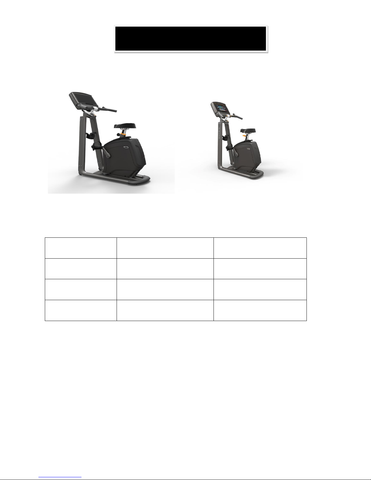
Matrix Retail U30 Matrix Retail U50
Specification
U30
U50
Handle Bar Type
Foam wrapped
PU wrapped
Seat Bottom Type
U30 seat with rail mount
U50 seat with rail mount
Resistance System
Internal ECB
Induction Brake
Product Browse
Page 3

3
Contents
CHAPTER 1: SERIAL NUMBER LOCATION ............................................................................................... 4
CHAPTER 2: CONSOLE INSTRUCTION ..................................................................................................... 6
CHAPTER 3: TROUBLESHOOTING
3.1 ELECTRICAL DIAGRAM-FRAME ..................................................................................................... 7
3.2 ECB/LCB WIRING INSTRUCTIONS ............................................................................................... 11
3.3 TROUBLESHOOTING .................................................................................................................... 13
3.3.1 NO POWER TO THE CONSOLE ........................................................................................... 13
3.3.2 TROUBLESHOOTING –SPEED DOES NOT DISPLAY ......................................................... 13
3.3.3 TROUBLESHOOTING – NO RESISTANCE OR INCORRECT RESISTANCE ........................ 14
3.3.4 TROUBLESHOOTING–HEART RATE ISSUES ..................................................................... 16
CHAPTER 4: PART REPLACEMENT GUIDE
4.1 CONSOLE REPLACEMENT ........................................................................................................... 17
4.2 HANDLEBAR REPLACEMENT ....................................................................................................... 18
4.3 PEDAL REPLACEMENT ................................................................................................................ 20
4.4 CRANK REPLACEMENT ................................................................................................................ 20
4.5 CONSOLE MAST COVER REPLACEMENT ................................................................................... 21
4.6 SIDE COVER REPLACEMENT ................................................................ ...................................... 22
4.7 ECB & LCB REPLACEMENT .......................................................................................................... 22
4.8 U50 ECB CONTROLLER REPLACEMENT ..................................................................................... 23
4.9 SEAT REPLACEMENT ................................................................................................................... 23
4.10 U30 SEAT POST REPLACEMENT ................................ ............................................................... 24
4.11 U50 SEAT POST REPLACEMENT ............................................................................................... 24
4.12 CUP HOLDER REPLACEMENT ................................................................................................... 25
Page 4
4
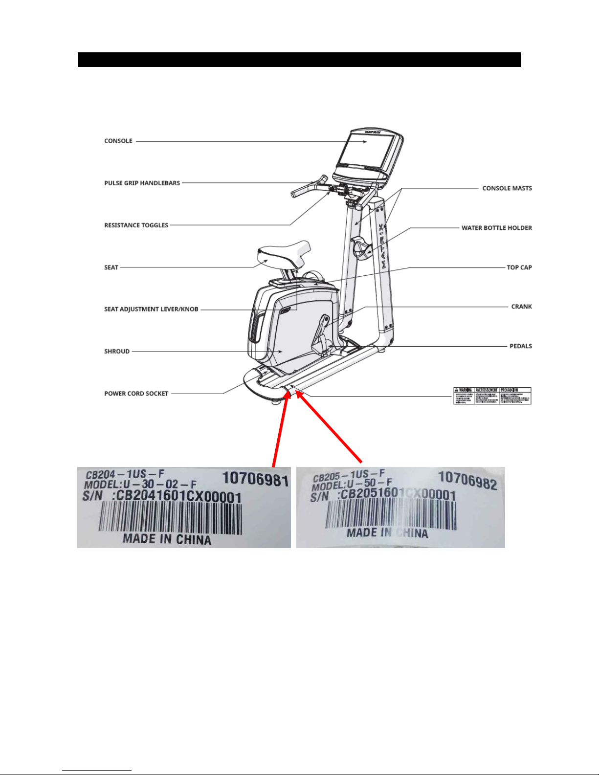
CHAPTER 1: Serial Number Location
MATRIX U30/U50 BIKE FRAME
Page 5
5
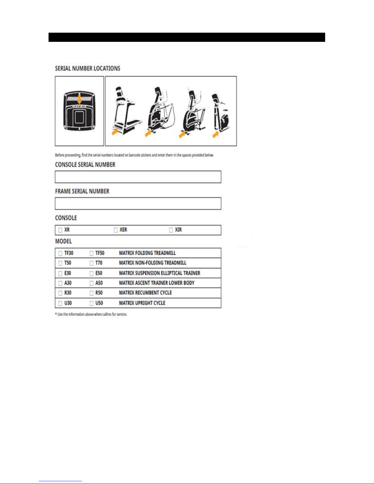
CHAPTER 1: Serial Number Location
Page 6
6
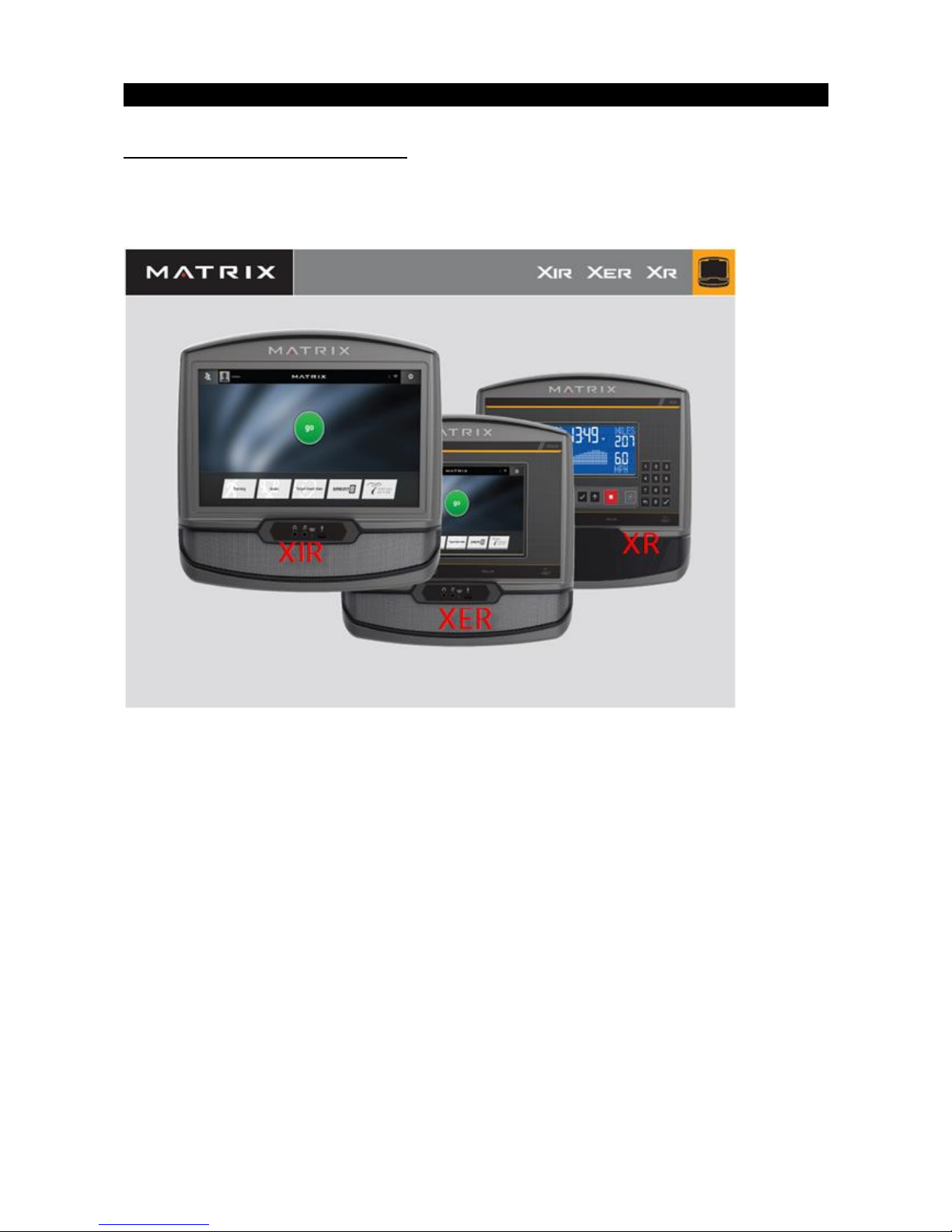
CHAPTER 2: Console Browse
XR/XIR/XER CONSOLE BROWSE
Please refer to XR/XER/XIR service manual to get more details.
Page 7
7
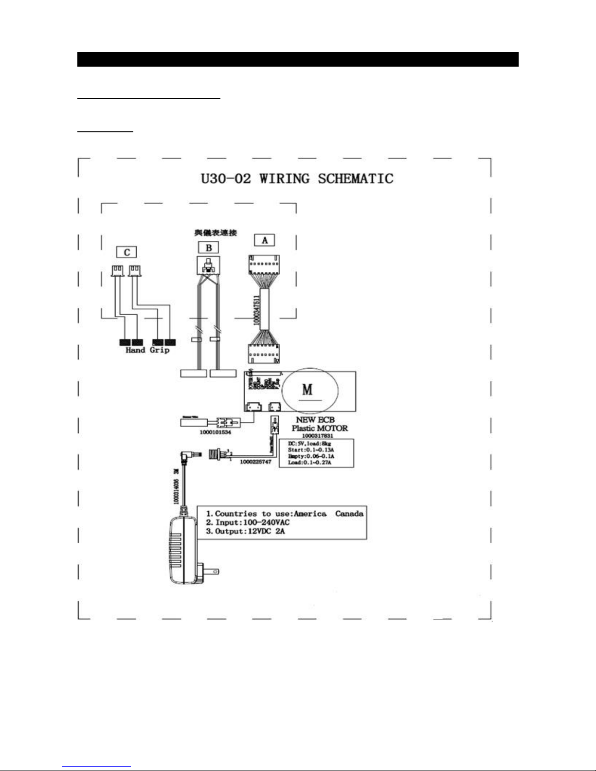
CHAPTER 3: Troubleshooting
3.1 ELECTRICAL DIAGRAM
U30 Frame
Page 8
8
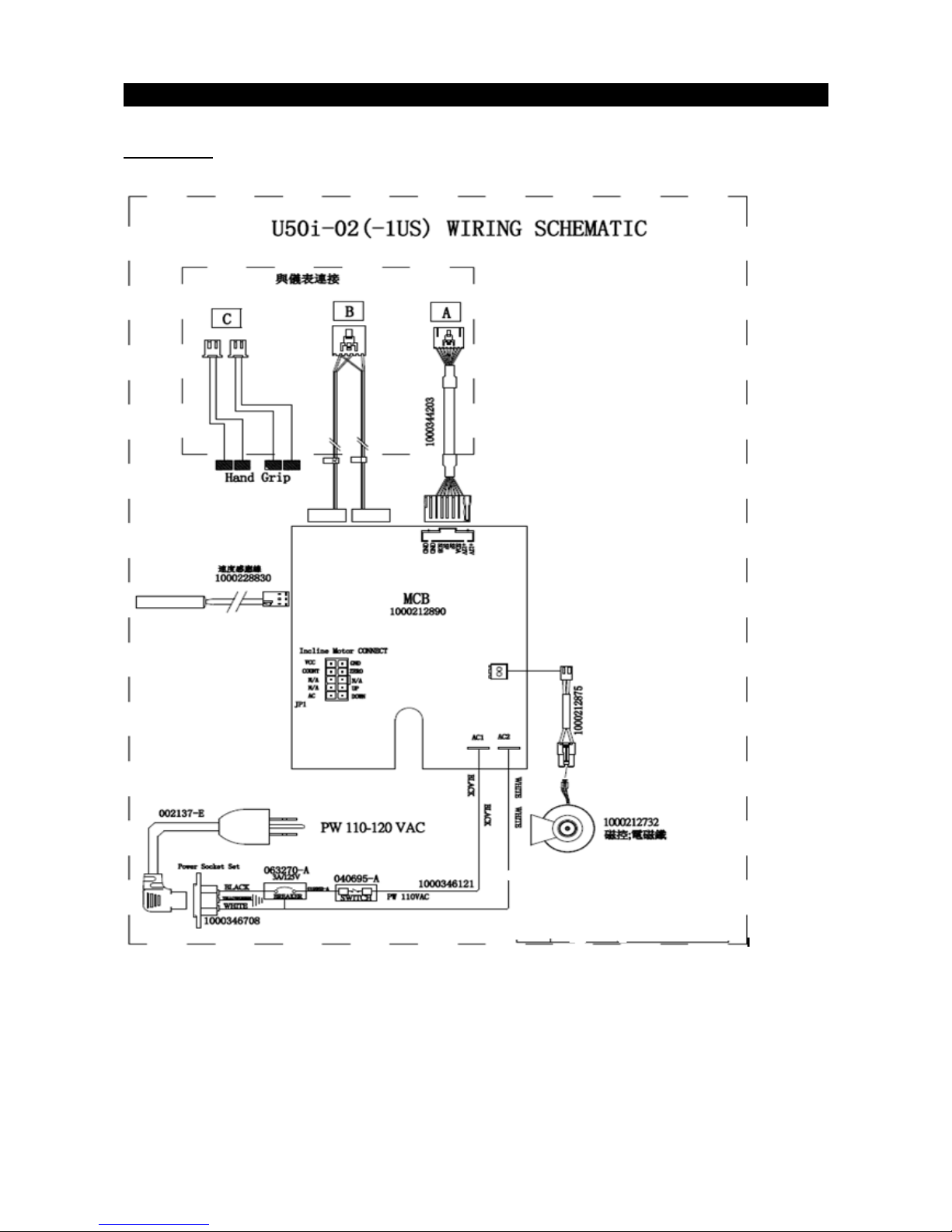
CHAPTER 3: Troubleshooting
U50 Frame
Page 9

9
CHAPTER 3: Troubleshooting
U30 Console Wire
U30 Speed Sensor
U30 Power Wire
Page 10

10
U50 Console Wire
U50 Speed Sensor
U50 External Powercord
Page 11

11
CHAPTER 3: Troubleshooting
3.2 ECB/LCB Connections
ECB Connections (U30)
CN1
Console Connector
CN2
Power Connector
CN3
Speed sensor
Page 12

12
CHAPTER 3: Troubleshooting
3.2 ECB/LCB Connections
LCB Connections (U50)
N1
Power Line In
N2
Speed sensor Socket
N3
Console Socket
Page 13

13
CHAPTER 3: Troubleshooting
3.3 TROUBLE SHOOTING
3.3.1 TROUBLESHOOTING – NO POWER TO THE CONSOLE
1) Symptom:
No power to the console.
2) Solution:
a. The adaptor for this model is 12V - 2A. Check to make sure the power adaptor on the unit is correct.
Test the power adaptor on a known good outlet. Replace the adaptor if it is defective.
b. Check the connection of the console cable at the console. Unplug the console cable from console, and
use a multi-meter to check the voltage through the console cable. Pin 1 or 2 and pin 7 or 8. it should be
12VDC. If no voltage is present, the console cable is defective, replace it.
c. If the voltage through the console cable is 12VDC, the console is defective, replace it.
3.3.2 TROUBLESHOOTING –SPEED DOES NOT DISPLAY
1) Symptom:
The speed value does not display on console
2) Solution:
1. Unplug power cord, remove the console and check that all connections to the console are secure and
not damaged or pinched.
2. Remove the side cover and check to see if the sensor wire is connected well.
3. Check to see if one corner of the sensor is aligned with the magnet and the distance less than 5mm.
Page 14

14
CHAPTER 3: Troubleshooting
3.3.3 TROUBLESHOOTING – NO RESISTANCE OR INCORRECT RESISTANCE
1) Symptom:
a. The resistance is not adjustable during an exercise.
b. The resistance is reversed or much too high.
2) Solution:
a. Please refer to XR/XER/XIR service manual to check console for correct model selection first
b. Remove the front shrouds. Turn on the console, and check the ECB motor. At resistance level 1, the
head of the steel rope should point towards the top right side (around 45 degrees – Fig A). If the head of
the steel rope points toward the bottom or left side, the resistance will be reversed, adjust the head of the
steel rope to the correct position.
c. Press the LEVEL UP key to adjust the resistance.
A) If ECB motor cannot move, the resistance will not be changed. The ECB motor or console cable is
defective. Check the console cable inserted in ECB motor. Re-connect the console cable first, if still not
working, test cable for damage. If test good, replace ECB motor.
Page 15

15
CHAPTER 3: Troubleshooting
3.3.3 TROUBLESHOOTING – NO RESISTANCE OR INCORRECT RESISTANCE
B) If the ECB motor can move, the resistance can be adjusted. If the resistance is still too high, check the
gap between orange block and the bottom. It should be within 1-2 mm.
If the gap is larger than 1-2 mm, the resistance will be heavier than normal. Adjust the cable to the correct
gap range.
3. If all above conditions are ok, and the resistance is still too high, inside magnet is defective Replace the
ECB.
Page 16

16
CHAPTER 3: Troubleshooting
3.3.4 TROUBLESHOOTING–HEART RATE ISSUES
Symptom: Heart Rate Function Does Not Work or is Reading Incorrectly
Solution:
1. The heart rate grips are not connected properly or are defective.
With a multi-meter set for DC voltage, place one terminal on each of the HR grip plates. The HR grip
should give a voltage reading of between 0.5 and 2.0VDC. If the voltage is not between 0.5 and 2.0VDC,
remove the 3 screws holding the HR grip together and check the connection of the HR grip wiring.
2. The heart rate grip wiring is damaged or not connected correctly.
Check continuity of the HR grip wiring.
Place one terminal of a multi-meter set for resistance on the HR grip wiring at the HR grip, and the other
terminal on the HR grip wiring at the console. An ohm reading of around 1 should be expected. If the
reading is higher than 1, replace the HR grip wiring.
3. The HR board is damaged
Remove the console. Remove the 6 screws holding the front of the console to the rear. Check the
connection of the HR board wiring to the UCB. If all the wiring is intact and has good contact, replace the
HR board.
4. The UCB is damaged.
If the HR board, HR grips, and HR grip wiring do not solve the issue, replace the UCB.
Page 17

17
CHAPTER 4: Part Replacement Guide
4.1 CONSOLE REPLACEMENT
1) Remove the 4 screws holding the console back cover to the console (Figure A).
2) Remove the 4 screws holding the console to the frame (Figure B).
3) Disconnect all connections from the console and remove the console from console mast. (Figure C).
FIGURE A FIGURE B
FIGURE C
4) Reverse steps to install the console.
Notes: Carefully push the wires into the console and mast until they are clear of the console / mast
connection.
Page 18

18
CHAPTER 4: Part Replacement Guide
4.2 HANDLEBAR REPLACEMENT
For U30
1) Remove the console (section 4.1).
2) Remove the four screws from the handlebar (Fig1).
3) Remove four screws on both heart grips (Fig2).
4) Disconnect heart rate wire from the plastic cover (Fig3).
5) Reverse the steps to install a new handlebar (Fig4).
Fig1 Fig2
Fig3 Fig4
Page 19

19
CHAPTER 4: Part Replacement Guide
4.2 HANDLEBAR REPLACEMENT
For U50
1) Remove the console (section 4.1).
2) Remove the four screws from the handlebar (Fig1).
3) Remove four screws on both heart grips (Fig2).
4) Remove four screws which lock the quick keys (Fig3).
5) Reverse the steps one to install a new handlebar (Fig4).
Fig1 Fig2
Fig3 Fig4
Page 20

20
CHAPTER 4: Part Replacement Guide
4.3 PEDAL REPLACEMENT
1) Using a 15mm pedal wrench, remove the pedal while firmly holding the opposite crank arm for
leverage. (Figure A)
Note: The left pedal is reverse-threaded.
2) Install the new pedal.
FIGURE A
4.4 CRANK REPLACEMENT
1) The crank arm is fixed with a self-extracting crank bolt. You must lubricate under extractor cap before
removing the crank bolt. If this is not done, damage can happen to the crank arm or extractor.
2) With an 8mm hex key, turn the crank bolt counter-clockwise to remove crank arm. The torque is
800lbs (Figure A).
3) Reverse to replace the crank arm.
FIGURE A
Page 21

21
CHAPTER 4: Part Replacement Guide
4.5 CONSOLE MAST COVER REPLACEMENT
1) Remove the two top covers by hand (Figure A and B).
2) Remove console mast by removing the four screws. (Figure C).
FIGURE A FIGURE B
3) Remove the head cover by removing the four screws (Figure D), and raise the cover out of the way
(Figure E).
FIGURE C
FIGURE D FIGURE E
Page 22

22
CHAPTER 4: Part Replacement Guide
4.6 SIDE COVER REPLACEMENT
1) Remove head top covers by hand (section 4.5).
2) Remove crank arms (section 4.4).
3) Remove the screws from the covers.
4) Remove the covers.
5) Reverse steps to replace covers.
4.7 ECB & LCB REPLACEMENT
1) Remove the covers (section4.6).
2) Disconnect wires and remove four screws for the ECB (two screws for LCB).
3) Reverse steps to replace ECB or LCB.
ECB LCB
Page 23

23
CHAPTER 4: Part Replacement Guide
4.8 U50 ECB CONTROLLER REPLACEMENT
1) Disconnect wires of induction brake and any wire ties.
2) Loosen 4 fixing bolts one full turn.
3) Loosen tension bolts nuts to remove drive belt.
4) Remove 4 fixing bolts and remove ECB unit.
5) Reverse steps to replace ECB unit.
NOTE: Drive belt tension 135-155Hz.
4.9 SEAT REPLACEMENT
1) Remove the 2 seat screws (circled below).
2) Remove seat and seat clamp.
3) Reverse steps to install seat.
Page 24

24
CHAPTER 4: Part Replacement Guide
4.10 U30 SEAT POST REPLACEMENT
1) Remove seat pad-(section 4.7).
2) Back out pull pin (Fig1).
3) Take sleeve(Fig1)out,and then you can replace seat post.
Fig1
4.11 U50 SEAT POST REPLACEMENT
1) Remove the side covers.
2) Remove 2 screws from the top seat post sleeve.
3) Lift seat post and seat post sleeve out of the frame.
4) Replace seat (section 4.9).
5) Reverse steps to replace seat post.
Page 25

25
CHAPTER 4: Part Replacement Guide
4.12 CUP HOLDER REPLACEMENT
1) Remove the 4 screws. (Figure A).
2) Install new cup holder.
 Loading...