

Page 1
JOHNS
O
A
Kyl
J
o
N
Issu
eRevda
A
pproval
e Schweit
z
hns
o
date 20
1
ision
te
er
n In
d
TF3
6-09-27
ustri
e
0/TF
5
Ser
v
Editio
n
Edition ti
Revie
w
s (S
h
0/T5
0
ice
M
01
e01
ang
h
-02/T
7
anua
l
Doc N
o
Page
ai)
C
0-02
. SM-T
M
Editor
A
lex Tan
g
o., L
t
1
-AF-003
26
d
2017-08-08
Page 2
M
M
atrix
R
atrix
R
etail T
etail T
5
F30
0-02
Produ
ct Bro
Mat
r
Matri
x
wse
ix Ret
a
Retail
il TF50
T70-0
2
2
Page 3

3
Contents
CHAPTER 1: SERIAL NUMBER LOCATION ................................................................................................... 4
CHAPTER 2: TROUBLESHOTING
2.1 Electrical Diagram…………………………………………………………………………………………………5
2.2 MCB instructions……………………………………….……………………………….…………………….......8
2.3.1 Troubleshooting - No Function For Safety Key ................................................................................... 12
2.3.2 Troubleshooting - No Response For Machine When Pressing Start……………………………………..13
2.3.3 Troubleshooting - Incline Motor Issues ................................................................................................. 14
2.3.4 Troubleshooting - Noise Issues ............................................................................................................ 15
2.3.5 Troubleshooting - Heart Rate Function Issues ..................................................................................... 16
CHAPTER 3: PART REPLACEMENT GUIDE
3.1 Motor Replac
ement .................................................................................................................................. 17
3.2 Side Rail Replacement ............................................................................................................................ 19
3.3 Rear Roller Replacement ......................................................................................................................... 20
3.4 Running Deck Replacement .................................................................................................................... 21
3.5 Front Roller Replacement ........................................................................................................................ 22
3.6 Running Belt Replacement ...................................................................................................................... 23
3.7 Motor Control Board (MCB) Replacement ............................................................................................... 24
3.8 Incline Motor Replacement ...................................................................................................................... 25
3.9 Console Replacement
..............................................................................................................................26
Page 4
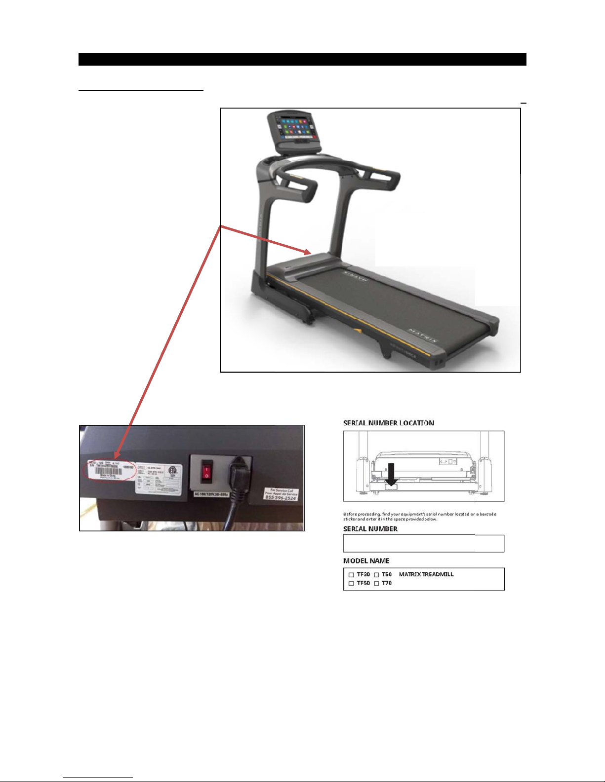
Serial N
u
mber Lo
c
C
H
ation
APTER 1 : Serial N
u
mber Location 4
Page 5
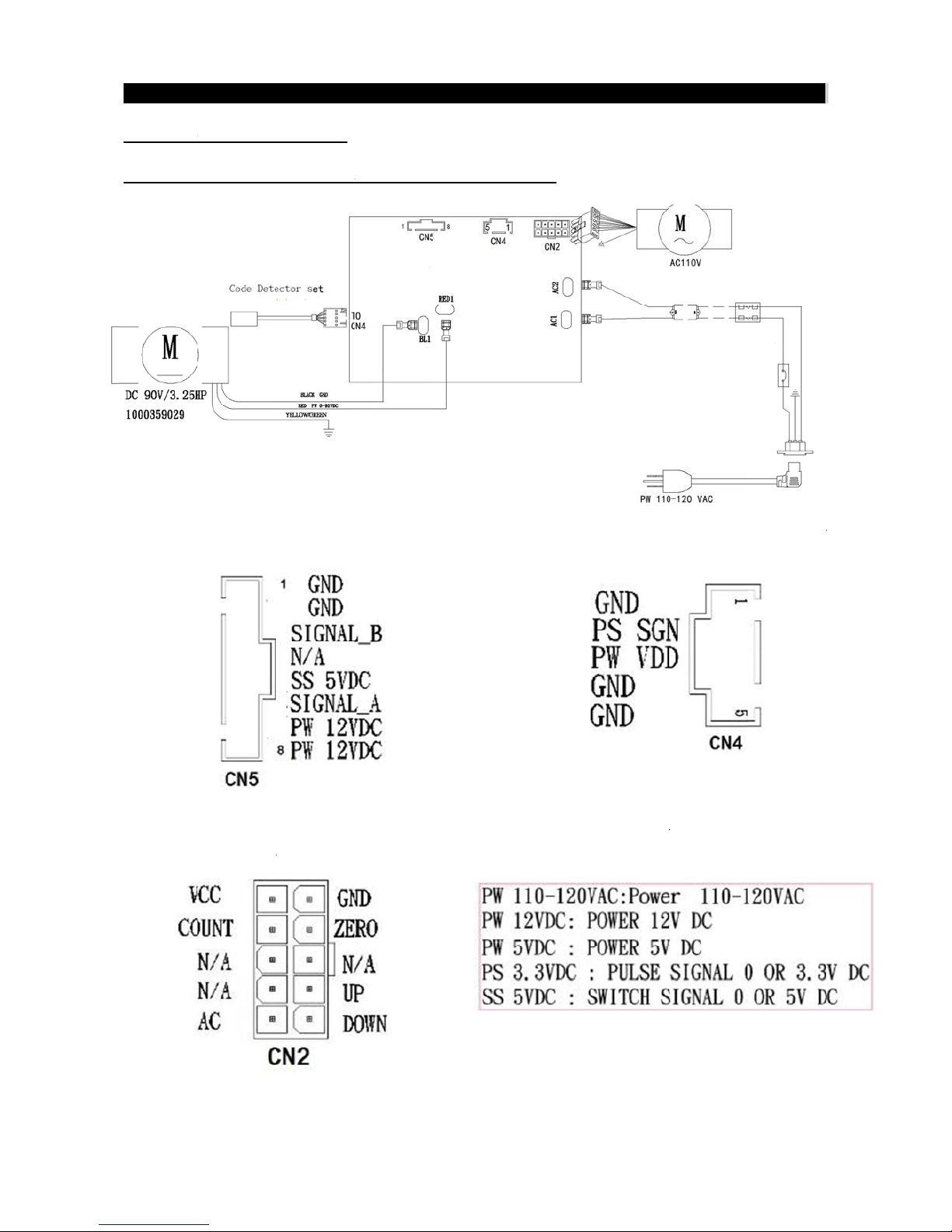
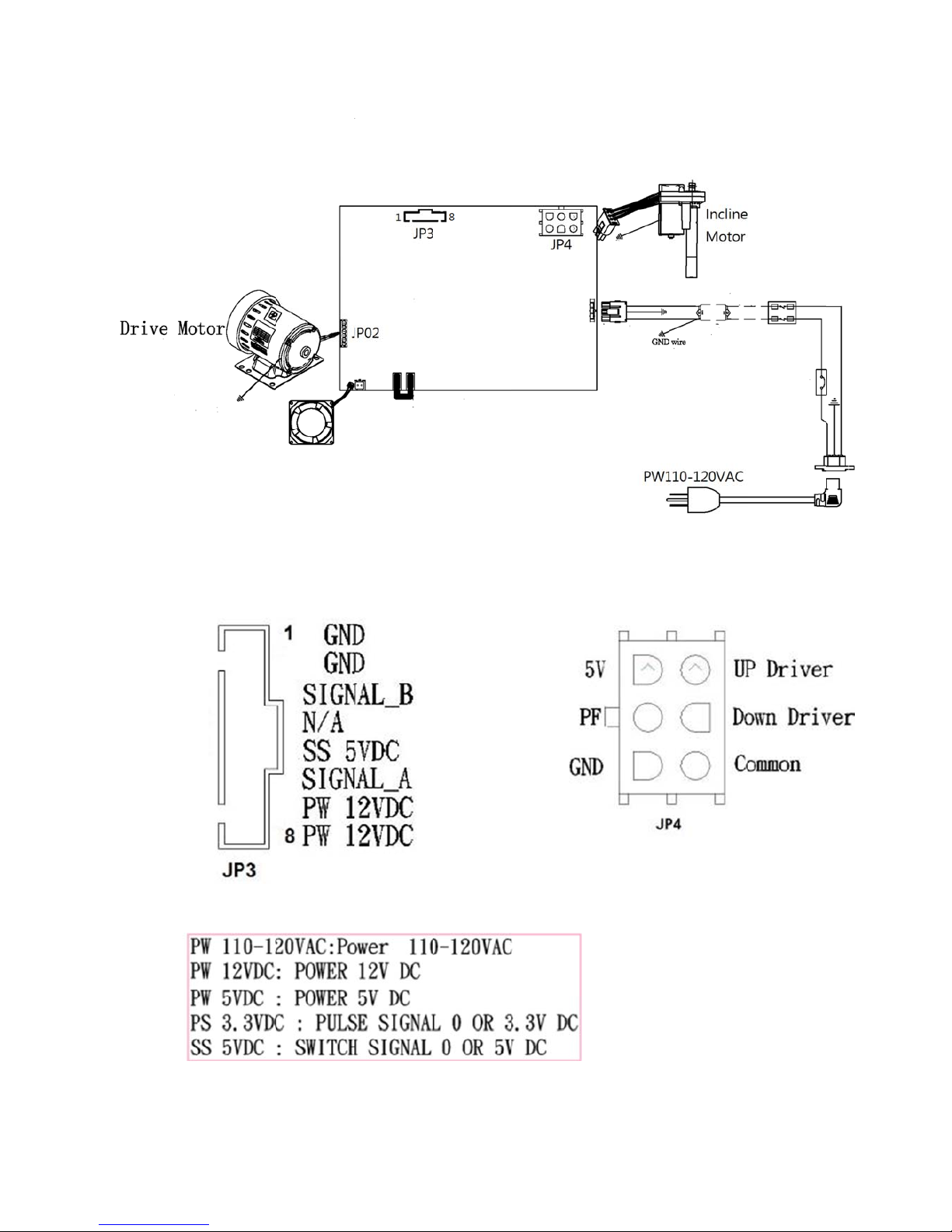
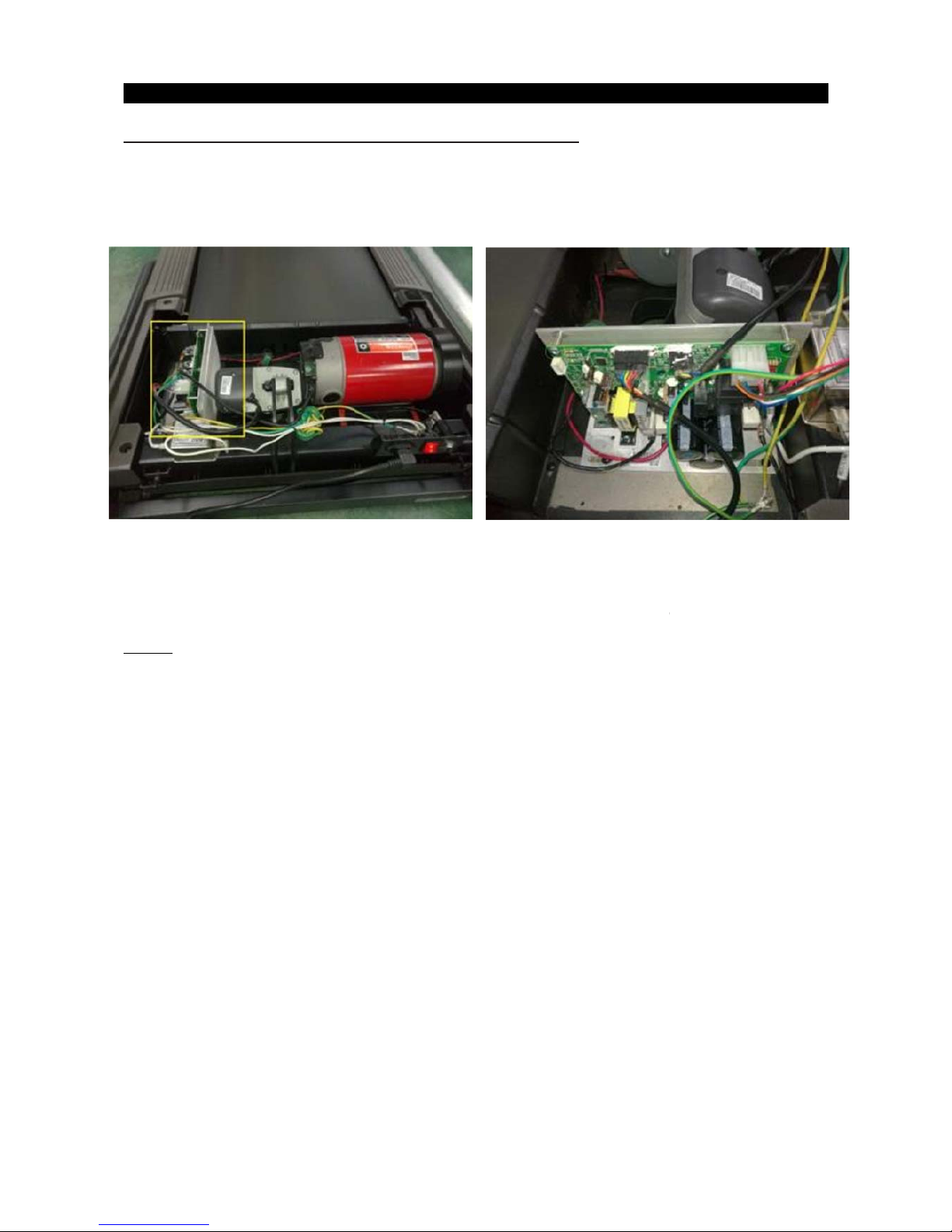
2.1 ELEC
1. MCB E
Fig-1 the
M
Fig-
3
TRICAL
D
LECTRIC
A
CB TO CO
The MCB
T
PIN
L
IAGRAM
L DIAGR
A
NSOLE PIN
O INCLINE
AYO U T
CHAPTE
R
M---TF3
0
LAYOUT
MOTOR
2: Trou
/
TF50/TF
Fig
-
bleshooti
n
50-02
2 the MC
B
TH
g
TO SPEE
D
E PIN VOLT
A
SENSOR
P
GE INFO
R
5
IN LAYOU
T
MATION
Page 6
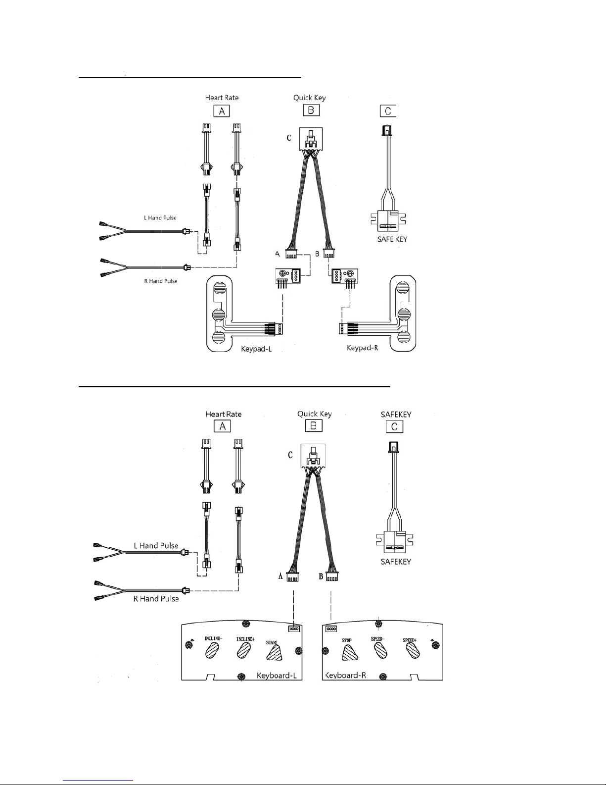
CONSO
L
2. CONS
O
E ELECT
R
LE ELE
C
ICAL DI
A
TRICAL
D
GRAM---
T
IAGRAM
F30
---TF50/T50-02/T70-02
6
Page 7
3. MCB E
Fig-1 t
h
LECTRIC
A
e MCB TO
C
Fig-3 Th
e
L DIAGR
A
ONSOLE
P
PIN VOLT
A
M---T70
-
IN LAYOU
T
GE INFOR
M
02
ATIO N
Fig-1 MCB TO INCLINE PI7N LAYOUT
Page 8

2.3. MCB
1. TF30/
T
CN1
CN2
CN3
CN4
CN5
CN6
instructio
n
F50/TF50
-
Power Line
Incline mot
o
Drive motor
Speed sens
Console ca
b
Software b
u
s
02
in terminals
r power cab
cable termi
n
or cable so
c
le socket
rning cable
s
le socket
als
ket
ocket
Fig -1
8
Page 9
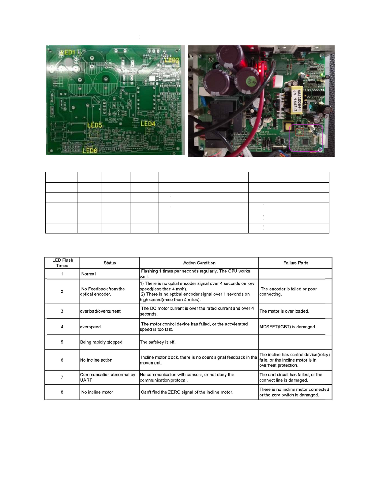
2. MCB L
Table1-M
C
LED No
LED1
LED2
LED4
LED5
LED6
Table2-M
C
ED’s func
t
B LED FU
Color A
Red li
g
Green li
g
Green fl
a
Green li
g
Green li
g
U STATU
S
ion indica
t
NCTION
ctive In
a
ht on lig
h
ht on lig
h
sh
-
ht on lig
h
ht on lig
h
(LED4)
or (TF30/
T
ctive Fu
n
t off Dri
v
t off MC
----- MC
t off Incl
t off Incl
F50/TF5
0
ction
er Motor ac
t
B Power ind
U status se
e
ine down in
d
ine up indic
a
-02)
ive
icator
Table2
icator
tor
Sym
p
Not
v
Not
v
See
T
Rela
y
Rela
y
ptom
oltage to dr
oltage outp
u
Table2
y not active
y not active
9
ve motor
t
MCB fail
MCB fail.
Page 10

3. MCB
C
JP01
JP02
JP3
JP4
JP05
IRCUIT B
O
Drive m
o
Power Li
Console
Incline
m
Fan cabl
e
FI
F
ARD IN
S
tor cable so
c
ne in socket
set cable so
otor cable s
o
socket
TRUCTI
O
Fig-1
ket
ket
cket
NS (T70-02)
1
0
Page 11

4. MCB L
Table1-MC
B
T
Table 2-
M
ED’s funct
LED FUN
C
CU STATU
ion indica
t
TION
S (LED6)
or -TF70-02 (Fig1&Fig2)
11
Page 12

12
CHAPTER 2: Troubleshooting
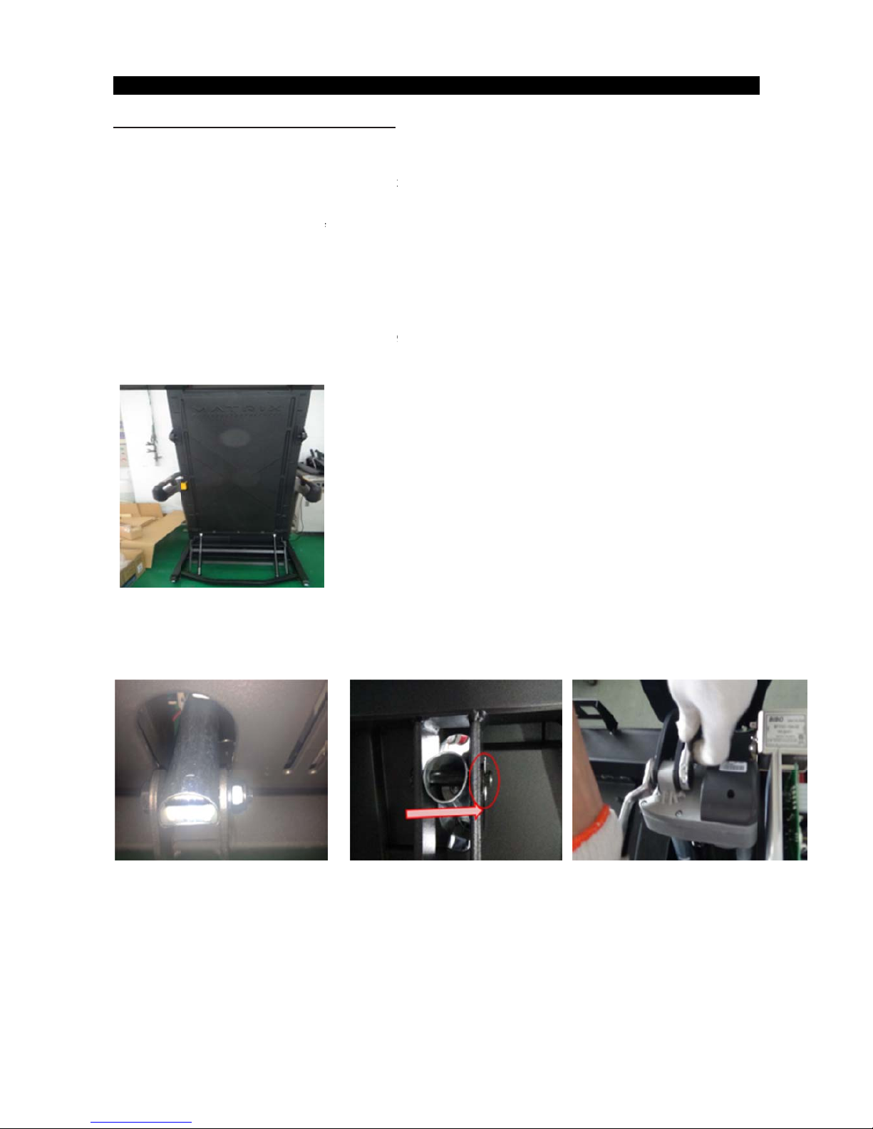
2.3.1. TROUBLESHOOTING – NO FUNCTION FOR SAFETY KEY
SOLUTION:
a.Check if the safety key is totally inserted into the console.
- If not, remove and insert again.
b.
Check if the s
afety key is oxidized or damaged.
- If yes, try cleaning it or replace it.
c. If the safety key is not damaged, check the alignment of the reed switch (safety key sensor)
and wire connection in the console.
Page 13

13
CHAPTER 2: Troubleshooting
2.3.2 TROUBLESHOOTING – NO RESPONSE FOR MACHINE When Pressing Start
SOLUTION:
a. Check if the console beeps when all keys are pressed. If no, replace the keypads
b. Enter Engineering Mode, and scroll to ENG 1 (Hardware Test). Press the “ENTER” key first and
then the key “START”.
- When press the key “SPEED + / -“, if the data on windows “TIME” & “DISTANCE” change, the
Console is ok. If not, replace the UCB.
c. Verify the motor or running belt spins freely - remove any obstructions from under the running belt
or motor compartment that may cause a block in movement.
d.
Check the console cable connection. Also, console cable continuity can be tested with Ohms
on each wire of the cable.
e. Test the drive motor.
1. 30/50 series short test - Disconnect power from the unit. Remove the motor cover. Remove
the red and black motor wires from the MCB. Using a jumper wire (or metal paper clip), make
the connection between the red and black leads of the motor. Without the jumper wire, the running
belt will move freely with little to no resistance. With the jumper wire in place there will be a great
amount of resistance when trying to push the running belt. If there is resistance, the motor is good.
30/50 series battery test - Disconnect power from the unit. Remove the motor cover. Remove the
red and black motor wires from the MCB. Using a DC battery from a cordless drill or other device,
touch the red on the positive lead of the battery and the black to the negative lead. If the motor
runs, the motor is good.
2. 70 series windings test - Disconnect power from the unit. Remove the motor cover. Remove the
motor connection from the MCB. With an Ohm meter test the resistance level between the
motors three phases; pin 1 and pin 2, pin 1 and pin 3, then pin 2 and pin 3. If all three resistance
levels are the same, the motor is good. If one or more are different, replace the motor.
f. If the drive motor is ok. Then,
- Check the connection of the speed sensor (encoder disk group) at the MCB.
- Remove the speed sensor from the motor and clean it, then re-test.
- If the speed sensor is clean and has a good connection but still will not operate, replace the speed
sensor.
- Replace the MCB as the last step if machine does still not run after to take above actions.
Page 14

14
CHAPTER 2: Troubleshooting
2.3.4 TROUBLESHOOTING - INCLINE MOTOR ISSUES
SOLUTIO
N:
a. While using the machine press the "INCLINE" keys, the console should beep and display incline
change, if no, replace the key pad
.
b. Enter Engineering Mode, and scroll to ENG 1 (Hardware Test). Press the “ENTER” key
first and then the “START
” key.
c.
Press the “INCLINE ▲/▼” key.
If can hear clicks from two relays and LED light (see table 2.2.2 and 2.2.4) at the MCB,
the MCB is
ok.
Then check the connection of the elevation motor at the MCB. Firs
t try to unplug and re-plug
connection . If this does not resolve the i
ssue, replace the elevation motor.
If there is no clicks from these two relays or LED light, MCB is defective and replace the MC
B.
Page 15

15
CHAPTER 2: Troubleshooting
2.3.4 TROUBLESHOOTING - NOISE ISSUES
SOLUTION:
a.Thumping noise twice per rotation on new machine
.
This noise is from the roller or running belt.
-If this is a new unit, some noise is normal as the running belt forms around the rollers.
-
Check that the belt is centered and tensioned co
rrectly.
-
Remove and clean the rollers if needed.
-
Replace the rollers or running belt as nee
ded.
b. High pitched “bell
-like” sound from under the motor cover.
This sound is likely a moving component.
-Remove the motor cover and check the drive belt for alignment and make sure it is not slipping or is
frayed / cut in any way.
Replace the driv
e belt if needed.
-
Make sure the optic disk on the motor is not rubbing the speed sensor
.
-
Turn the motor by hand to see if motor bearings are rubbing. Replace the motor if ne
eded.
-
Check the front and rear rollers, replace if need
ed.
c
. Rubbing / grinding noise.
This sound is likely caused by the optic disk.
-
Check that the optic disk is tight on the motor and not rubbing the speed se
nsor.
d. Banging or clunking sound/slapping / squeaking sound with each footstep.
T
he sound is likely due to the unit not being level.
-Check that all levelers are touching the ground.
-Move the treadmill to another flat surface.
-Thi
s sound is from the runni
ng deck / belt.
-Remove the side rails and tighten the deck bolts and elastomers.
-Check the deck shocks for disintegration or crumbling. Replace if needed.
e. Rubbing sound underneath the treadmill.
This sound is likely due to the air shock.
-Lubricate or repl
ace the air shock as needed
.
f. Squeaking / grinding noise when using elevation.
This sound is likely from the incline motor.
- Check that the incline motor and incline rack connection points to the main frame are tight.
Replace Teflon washers on the frame as needed.
-Lubricate the in
cline motor worm screw and connection points wi
th grease.
-
Replace the incline motor.
Page 16

16
CHAPTER 2: Troubleshooting
2.3.5 TROUBLESHOOTING- HEART RATE FUNCTION ISSUE
SOLUTION:
a.Telemetric heart rate:
1. Re-center
the chest strap below the user's pectoral muscle and check again.
2.Replace the battery in the chest strap
.
b.Heart rate gr
ip:
1.
W
et the use
r's hand, and then reestablish contact with the HR grip.
2.Replace new HR grip if console can display proper HR rate.
W
ith a multi-meter set for DC voltage, place one terminal on each of the HR grip plates. The HR
Grip should give a voltage reading of between 0.5 and 2.0VDC. If the voltage is not between 0.5
And 2.0VDC, remove the screws holding the HR grip together and check the connection of the
HR grip wiring.
3.Check a-d. If still cannot work, Suggest install new console.
Page 17
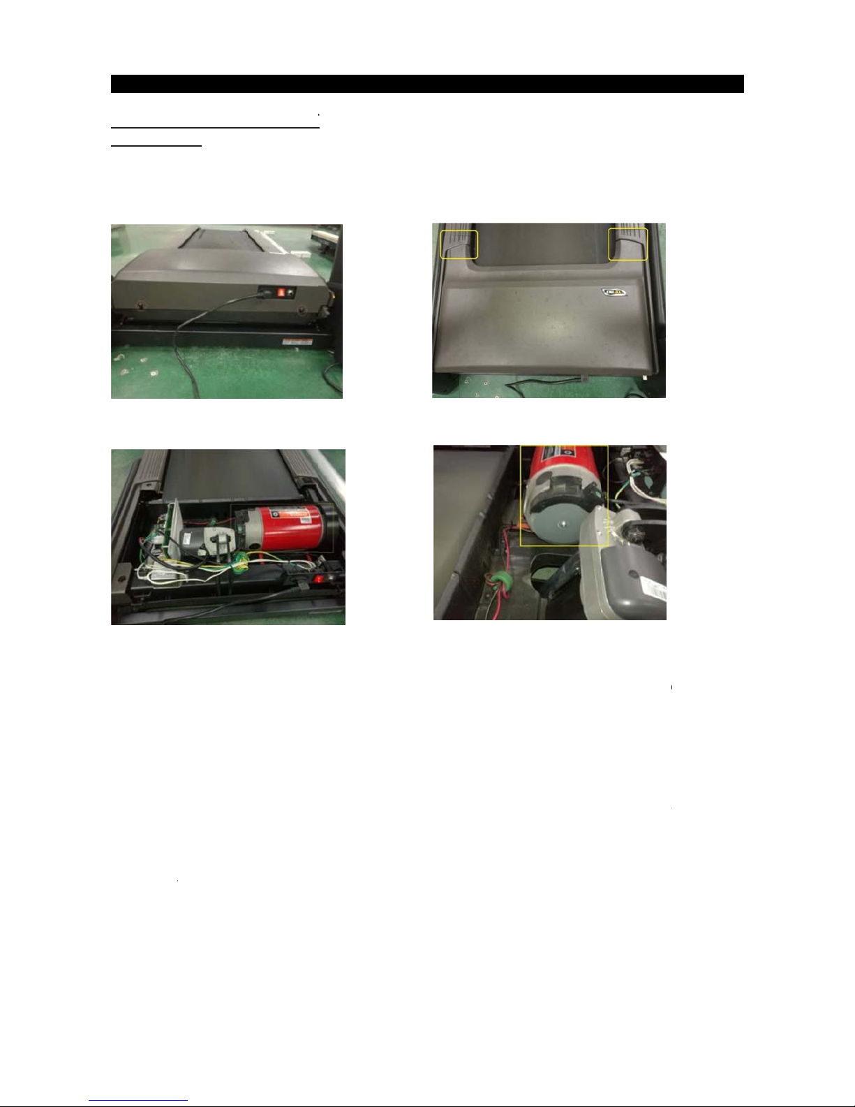
3.1 MOT
O
1.TF30/T
F
1) Discon
n
2) Remov
3) The co
v
4) Fig-3 &
F
5) Unplug t
h
6) Remove
outer ed
g
7) Remove
8) Rever
se
pulley. In
s
the drive
10) Test at
v
R REPL
A
50
ect power
c
e the 2 scre
w
er is secur
e
ig-4 shows
t
e motor co
n
the drive be
e of the tre
a
the four mo
t
steps to ins
t
tall belt on
d
belt, roll the
arious spe
e
C
H
CEMEN
T
ord.
s holding t
h
d to the fra
m
he motor M
C
nector from
lt by spinnin
g
dmill.
or bolts and
all motor.
W
rive motor
p
belt on. Co
n
ds.
APTER
3
e motor co
v
e with Velc
r
Fig-1
B area wit
h
Fig-3
LCB, speed
the flywhe
e
remove mo
t
hen installin
g
ulley. Then
tinue to wal
k
: Part R
e
er to the fra
m
o so you wil
the motor
c
sensor, cut
l (or runnin
g
or.
Flexonic d
by rotating
t
belt on unt
i
placeme
n
e (Fig-1)
l have to pul
over remov
e
any wire tie
s
belt) and
w
rive belt, sta
he front roll
e
l centered o
t Guide
l up with so
m
d. (Fig-3 &
F
as needed
.
alking the d
r
t with belt o
n
r pulley whil
both pulle
y
e force (Fi
g
ig-4)
.
ive belt off t
o
n inside of f
r
e applying
p
s.
1
7
-2)
Fig-2
Fig-4
ward the
ont roller
ressure on
Page 18

2.
MOTOR
1) Discon
n
2) Remov
e
3) Note.
T
3) Disconn
e
4) Remov
e
5) Remov
e
6) Revers
e
Note: wh
e
rol
7) Test at v
a
R
ect power
c
the 2 scre
w
he cover is
Fig
-
ct motor wi
r
Fig
-
spring fro
m
4 bolts se
c
steps to in
s
n installing
ler pulley.
rious spee
d
REPLACCEMENT (Cont'd)
ord.
s holding t
h
secured to
t
1
es and grou
3
the belt te
n
uring motor
tall motor.
R
the drive be
l
s.
T70-02 ONLY
e motor co
v
he frame wi
t
nds, cut any
sioner. R
e
and remove
eplace any
t, rotate by
h
er to the fra
m
h Velcro so
wire ties as
move drive
b
motor from
wire ties th
a
and severa
l
e (Fig-1).
you will hav
e
needed.
elt from m
o
drive comp
a
t were remo
rotations,
m
to pull up
w
tor pulley.
rtment.
ed.
ake sure it i
s
ith some fo
r
s aligned wi
t
1
8
ce (Fig-2)
Fig-2
Fig-4
h the front
Page 19
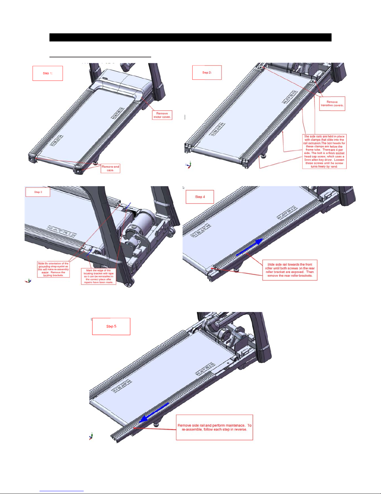
3.2 SIDE RAIL RE
P
C
H
LACEME
APTER
3
NT
: Part R
e
placeme
n
t Guide
1
9
Page 20
3.3 REA
R
1) Remov
e
2) Remov
e
3) Replac
e
4) Revers
e
Not
e
1. be s
u
2. Over
3.
A
lwa
y
4. Final
to st
o
ROLLE
R
side rail in
rear roller
new rear r
o
step 2 to s
t
Fi
g-1
re to set th
e
or under te
n
ys bring ten
s
steps of ten
p the belt
w
5.
C
H
REPLA
C
section 3.2
ller and tig
h
ep 1
correct run
n
sion can re
s
ion up eve
n
sioning are
w
ith you r fee
t
APTER
3
EMENT
tness bolts
(
ing belt ten
s
ult in dama
g
ly from the l
e
hen the ru
n
using an a
b
: Part R
e
Fig-1)
ion after re
p
e or injury.
ft to right t
e
ning belt jus
rupt stop at
placeme
n
lacing the
b
nsioning bol
t stoops slip
p
a walking s
p
1 bolt
t Guide
elt.
s using sm
a
ing and slo
w
eed.
each side
ll adjustme
n
s the moto
r
2
0
ts.
when trying
Reference section 3.6 note 2 to adjust the running belt.
Page 21
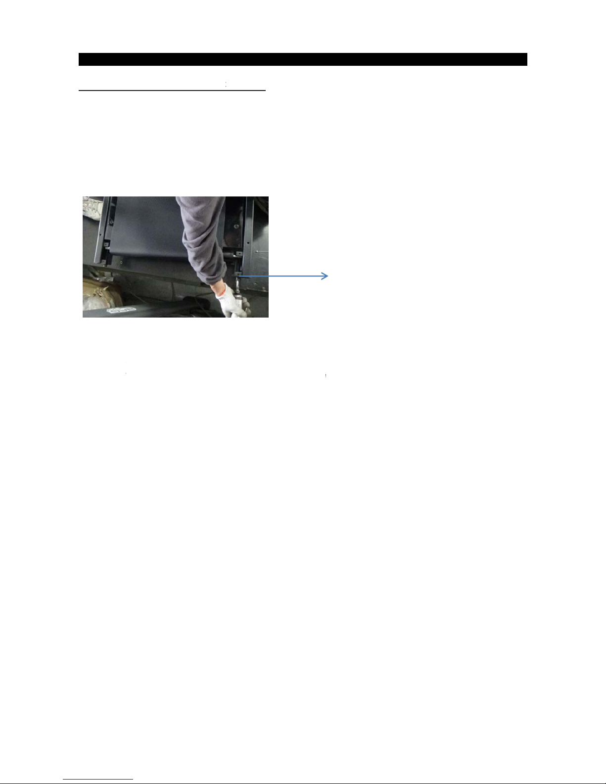
3.4 RUN
N
1) Remov
e
2) Remov
e
3) Remov
4) Remov
5) Remov
6) Revers
Note:
1
. The run
new runnin
g
2. For the
ING DEC
the motor
c
rear roller
a
e the side r
a
e the runnin
g
e the runnin
g
e steps 1-5
t
ning deck
is
belt and o
n
A
DJUSTIN
G
C
K REPLA
C
over as out
l
s outlined i
n
il as outline
d
deck 8 bol
t
deck from
o install a n
e
silicon on o
n
ly T70-02
m
THE RUN
N
HAPTER
EMENT
ined in Sect
section 3.
2
in Section
3
s and grou
n
the frame.(
F
w running
d
Fig-1
e side onT
F
odels is par
a
ING BELT
3: Part
R
ion 3.1.
.3.
d strap.
ig-1)
eck.
30/TF50. N
e
ffin waxed
d
reference s
e
eplacem
e
w deck surf
a
eck only 1
s
ction 3.6 no
t
nt Guide
ces must A
ide.
e 2
LWAYS be
m
21
atched to a
Page 22

3.5 FRO
N
1) Remove
2)
3)
Fi
g
3) Remov
e
4) Remov
e
5) Revers
e
T ROLL
E
the motor c
o
T70-02 only:
-1
the drive b
front roller
steps to re
C
H
R REPLA
ver as outli
n
elt from the
m
bolts and re
APTER
3
EMENT
ed in Secti
o
otor pulley
move front r
o
: Part R
e
n 3.1.
.(Fig-1)
ller and dri
v
place front roller and drive belt.
placeme
n
Fig
-
e belt.
t Guide
2
2
2
Remove the spring from the drive belt tensioner (Fig-2). The tensioner should now pivot
away from the drive belt.
Loosen both of the rear roller bolts to remove tension from the running belt (Fig-1).
Page 23
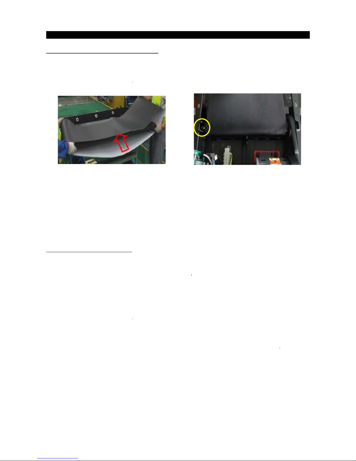
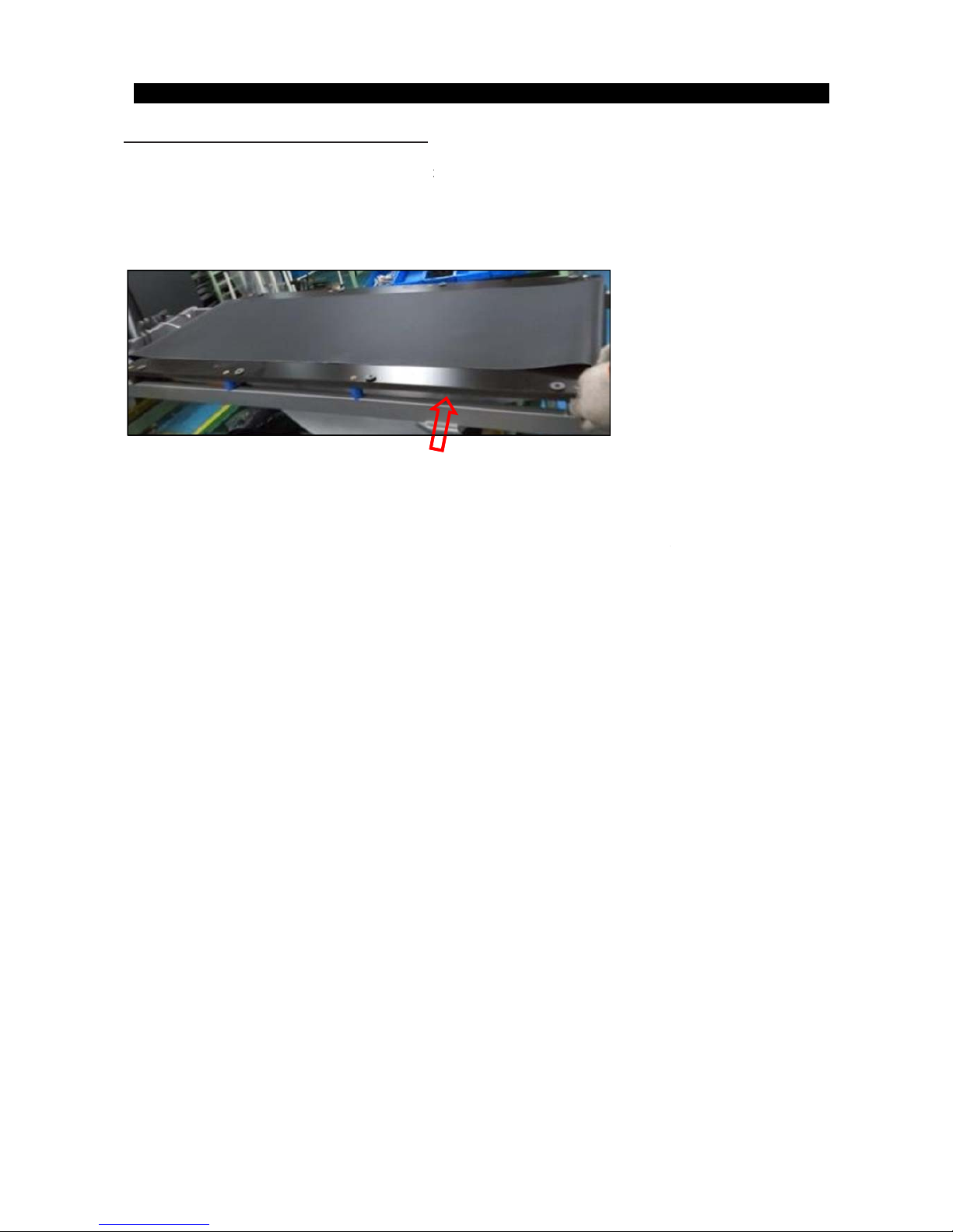
3.6 RUN
N
1) Rem
ove
2) Remove
3) Remove
4) Remove
5) Re
move
5) R
evers
e
Note1:
1. A
d
j
2. Th
e
matche
:
Note:2
A
DJUSTIN
G
After pla
c
centering.
T
cause the
b
direction b
e
Step1: Loc
a
frame at th
e
Step2:
Th
the belt is t
o
Manually c
e
as they we
r
Step3: Whil
Right
bolt
b
y
left tighten
t
remains ce
n
Step4: Che
c
should not
h
necessary.
ING BEL
T
the motor c
o
the rear roll
e
the running
the front roll
the running
Steps 1-5
t
ust running
running de
c
d to a new r
u
THE RUN
ing the trea
d
he belt may
elt to stretc
h
low.
te the two h
back of tre
a
ere should
b
uching one
nter the bel
t
e loosened.
e the tread
m
turning it c
l
he left bolt
b
tered for s
e
k the tensi
o
esitate or s
l
C
H
REPLA
C
ver as outli
n
r as outline
d
deck as outl
er as outlin
e
belt
Fig-1
o install a r
u
belt tension
k is silicon
o
nning belt
a
NING BELT
mill in the p
need to be
a
at different
ex head bol
t
dmill. Thes
e
e an equal
a
side, turn th
e
by pushing
ill is runnin
g
ockwise 1/4
y turning it
c
veral minut
e
n of the belt
ip. If this oc
c
APTER
3
EMENT
ed in Secti
o
in Section
3
ined in Secti
d in Section
nning belt.
after replac
e
n one side
o
nd Only T7
0
osition it will
djusted aft
e
rates. If the
on the rear
bolts adju
s
mount of s
p
bolts coun
t
the belt tow
a
at 3 mph,
o
turns, and l
o
lockwise 1/4
s.
. The belt s
h
urs, tighten
: Part R
e
n 3.1.
3.2.
on 3.4.
3.5.( Fig-2)
ment (Note
2
nTF30/TF
5
-02 models
be used, th
e
r the first 2
h
belt starts t
o
of the tread
m
t the rear ro
l
ace on eith
e
ter clockwis
e
rd the cent
e
bserve the
b
osen the le
f
turn and lo
o
ould be ver
y
the belt by t
placeme
n
)
0/TF50-2. N
is waxed de
belt must
b
ours of use
slip when a
ill. The bol
t
ler.
r side of the
approxima
t
r. Tighten
elt position.
t bolt 1/4 tur
n
sen the righ
snug. Whe
n
urning both
b
t Guide
Fig-
2
ew deck sur
f
ck only 1 si
d
e checked f
o
Temperatu
r
user is on it
s are locate
d
running bel
t
ely one full
t
the bolts th
e
If it is movin
. If it is mov
1/4 turn. R
e
a person
w
olts clockwi
faces must
A
e
r proper te
n
re and humi
d
, be sure to
f
at each e
n
and the sid
urn on eac
h
same amo
u
g to the righ
ing to the le
f
peat step 3
alks or run
o
se 1/4 turn,
2
3
LWAYS be
sion and
ity, and us
e
ollow the
d of the
rails. If
side.
nt of turns
, tighten th
e
t, tighten th
e
until the bel
t
n the belt, i
t
Repeat if
Page 24
3.7 MOT
O
1) Turn off
p
2) Remove
3) Remove
4) Remove
5) Remove
6) Reverse
Note. Re
p
R CONT
R
ower and d
the motor c
o
the wire co
n
the 2 screw
s
Fig-1
the MCB.
Steps 1-5 t
o
lace any wi
r
C
H
OL BOA
R
isconnect th
e
ver as outli
n
nectors at t
h
holding ea
c
install a M
C
e ties remo
v
APTER
3
D (MCB
)
power cor
d
ed in Secti
o
e MCB. (Fi
g
h side of th
e
B. Make su
r
ed.
: Part R
e
REPLAC
from the m
n 3.1.
-1)
MCB to th
e
e that all wi
r
placeme
n
EMENT.
achine.
frame (Fig
-
es removed
t Guide
2).
Fi
g
during Step -2 3 are re-co
n
2
4
nected.
Page 25
3.8 INCLI
1) Turn of
f
2) Remov
e
3) Disco
n
n
4) Lift or ti
5) R
emov
e
6) Remove
5)
Disconn
e
6) Reverse
6) Test ful
NOTE:
When insta
l
conn
ection
NE MOT
O
power to th
the motor
c
ect incline
m
lt the tread
m
the bolt fr
o
the bolt fro
m
Fig-1
ct the inclin
e
Steps 1-5 t
o
Fig-2
l range of el
e
ling a new i
n
points of th
e
C
H
R REPL
A
e treadmill
a
over as out
l
otor wires
f
ill until ther
e
m the eleva
t
the elevati
o
motor fro
m
install a ne
w
vation.
cline motor
,
incline mot
o
APTER
3
CEMENT
nd disconn
e
ined in Sect
rom MCB a
n
is access t
o
ion rack.(Fi
g
n with sprin
g
the top mo
u
incline mo
t
make sure
t
r .Replace
a
: Part R
e
ct the powe
r
ion 3.1.
d ground.
C
lower conn
-2)
g.
nting brack
e
or.
Fig-3
to replace t
h
ny wire ties
placeme
n
cord.
ut any wire
t
ecting bolt.
(
t (Fig-3).
e black zinc
that were r
e
t Guide
ies as need
e
Fig-1)
washers at
t
moved.
d.
Fig
-
the top and
b
2
5
4
ottom
Page 26

3.9 CON
S
1) Turn of
f
2)
Remov
e
3)
Discon
n
4)
Install t
h
5)
Turn o
n
OLE RE
P
power to th
the 4 scre
w
ect all wire
s
e new con
s
the power
a
Fi
g
Fig-3
C
H
LACEME
e treadmill
a
s holding t
h
from conso
ole by rever
nd select c
o
-1
APTER
3
NT
nd disconn
e
e console fr
le.
ing steps 1
rrespondin
g
: Part R
e
ct the powe
r
om the con
s
- 3.
model (Re
f
placeme
n
cord.
ole mast (Fi
g
erence XR/
X
t Guide
-1and Fig-
2
ER/XIR co
n
Fig
Fi
g
).
sole servic
e
-2
g-4
2
6
manual)
 Loading...