

Page 1

2018 T5X GROUP TRAINING
CONSOLE (TM537)
SERVICE MANUAL
Page 2

TABLE OF CONTENTS
CHAPTER 1: SERIAL NUMBER LOCATION ........................................................... 1
CHAPTER 2: IMPORTANT SAFETY INSTRUCTIONS
2.1 Electrical Requirements ............................................................................................. 2
CHAPTER 3: PREVENTATIVE MAINTENANCE
3.1 Recommended Cleaning Tips .................................................................................... 3
3.2 Check for Damaged Parts ......................................................................................... 3
3.3 Auto Calibration Procedure ....................................................................................... 3
CHAPTER 4: CONSOLE OVERLAY AND WORKOUT DESCRIPTION
4.1 Console Description .................................................................................................. 4
CHAPTER 5: MANAGER MODE
5.1 Manager Mode Overview ........................................................................................... 5
CHAPTER 6: ENGINEERING MODE
6.1 Engineering Mode Overview ...................................................................................... 8
CHAPTER 7: SERVICE MODE/TEST MODE
7.1 Service Mode Overview ............................................................................................. 9
7.2 Test Mode Overview................................................................................................... 10
CHAPTER 8: TROUBLESHOOTING
8.1 Electrical Diagram ...................................................................................................... 11
8.2 Error Codes List .......................................................................................................... 16
CHAPTER 9: PARTS REPLACEMENT GUIDE
9.1 Console Replacement ..................................................................................................... 20
CHAPTER 10: TREADMILL SPECIFICATIONS AND ASSEMBLY GUIDE
10.1 WiFi installation .............................................................................................................. 21
10.2 RFID installation ............................................................................................................. 27
10.3 T5X MYE TV Bracket Installation .................................................................................. 33
10.4 T5X PCTV Bracket Installation ...................................................................................... 37
10.5 RF900/863 Receiver Installation ................................................................................. 41
CHAPTER 11: SOFTWARE UPGRADE GUIDE
11.1 Software Upgrade Instructions for UCB ...................................................................... 46
CHAPTER 12: DOCUMENT UPDATE HISTORY
12.1 Document Update History ........................................................................................... 47
Page 3
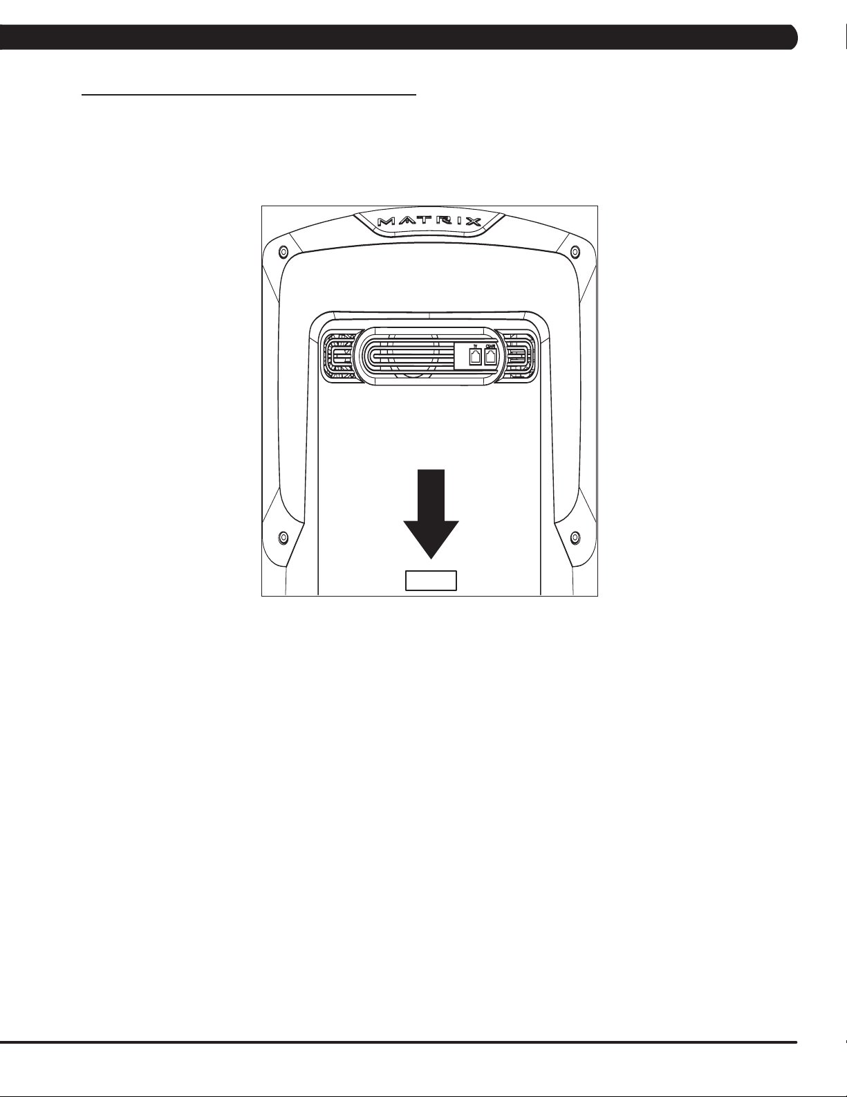
1.1 SERIAL NUMBER LOCATION
CHAPTER 1: SERIAL NUMBER LOCATION
CONSOLE SERIAL NUMBER LOCATION
T5X
1
Page 4
CHAPTER 2: IMPORTANT SAFETY INFORMATION
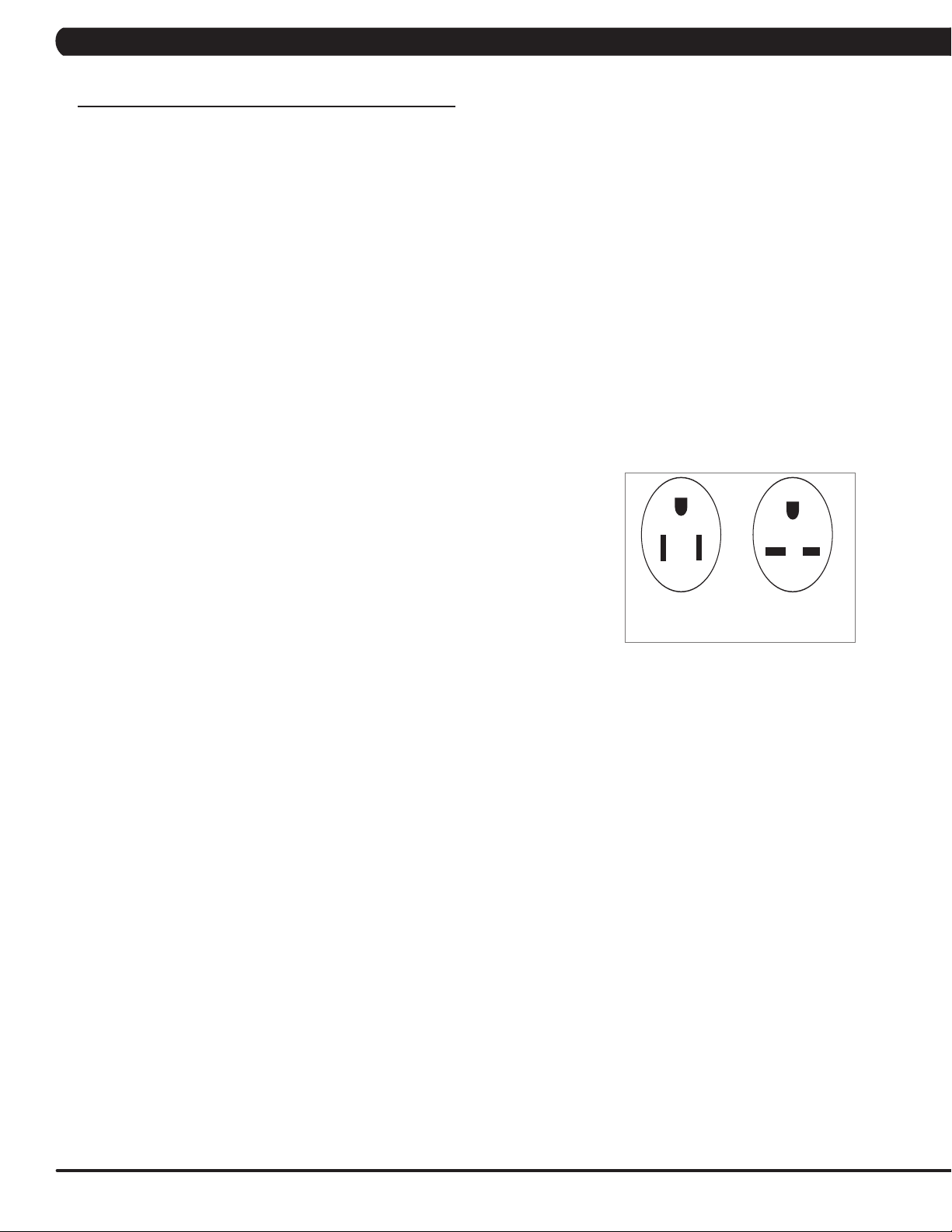
220 NEMA 6-15P
PLUG
110 NEMA 5-15P
PLUG
2.1 ELECTRICAL REQUIREMENTS
DEDICATED CIRCUIT AND ELECTRICAL INFO
A “Dedicated Circuit” means that each outlet you plug into should not have anything else running on that same circuit. The easiest way to verify
this is to locate the main circuit breaker box, and turn off the breaker(s) one at a time. Once a breaker has been turned off, the only thing that
should not have power to it are the units in question. No lamps, vending machines, fans, sound systems, or any other item should lose power
when you perform this test. Non-looped (isolated) neutral/grounding means that each circuit must have an individual neutral/ground connection
coming from it, and terminating at an approved earth ground. You cannot “jumper” a single neutral/ground from one circuit to the next.
ELECTRICAL REQUIREMENTS
For your safety and to ensure good unit performance, the ground on this circuit must be non-looped (isolated). Please refer to NEC article 210-21
and 210-23. Any alterations to the standard power cord provided could void all warranties of this product.
The 3x, 5x and 7xe bikes are designed to be self-powered and do not require an external power supply source to operate. Without an external
power supply, the console’s start-up time may be delayed. Add-on TV’s and other console accessories will increase the time needed for start-up.
An external power supply will ensure power is provided to the console at all times and is recommended when add-on accessories are used.
For units with an integrated TV (like the 7xe and 7xi), the TV power requirements are included in the unit. An RG6 coaxial cable with ‘F Type’
compression fittings on each end will need to be connected to the cardio unit and the video source. Additional power requirements are not needed
for the add-on digital TV (3x and 5x). For units with an add-on PCTV (3x and 5x), the TV power requirements are separate.
NOTE: ALL UNITS WITH VIRTUAL ACTIVE™ MUST BE POWERED!
110 V UNITS
All Matrix 3x, 5x, 7xe and 7xi 110 V bikes require the use of a 100-125 V, 60 Hz and a 15 A
“Dedicated Circuit”, with a non-looped (isolated) neutral/ground for power. This outlet should be a
NEMA 5-15R and have the same configuration as the plug. No adapter should be used with this
product. These bikes can be daisy-chained together with up to 4 units per 15 A dedicated circuit.
Matrix daisy-chain cord adapters are sold separately.
220 V UNITS
All Matrix 3x, 5x, 7xe and 7xi 220 V bikes require the use of a 216-250 V, 50 Hz and a 15 A
“Dedicated Circuit”, with a non-looped (isolated) neutral/ground for power. This outlet should be a
NEMA 6-15R and have the same configuration as the plug. No adapter should be used with this
product. These bikes can be daisy-chained together with up to 4 units per 15 A dedicated circuit.
Matrix daisy-chain cord adapters are sold separately.
GROUNDING INSTRUCTIONS
The unit must be grounded. If it should malfunction or breakdown, grounding provides a path of
least resistance for electric current to reduce the risk of electric shock. The unit is equipped with a cord having an equipment-grounding conductor and a grounding plug. The plug must be plugged into an appropriate outlet that is properly installed and grounded in accordance with all local
codes and ordinances. If the user does not follow these grounding instructions, the user could void the Matrix limited warranty.
North American power cord plugs shown.
Depending on your country, the plug type may vary.
ADDITIONAL ELECTRICAL INFO
In addition to the dedicated circuit requirement, the proper gauge wire must be used from the circuit breaker box, to each outlet that will have the
maximum number of units running off of it. If the distance from the circuit breaker box to each outlet, is 100 ft (30.5 m) or less, then 12 gauge wire
should be used. For distances greater than 100 ft (30.5 m) from the circuit breaker box to the outlet, a 10 gauge wire should be used.
ENERGY SAVING / LOW-POWER MODE
All units are configured with the ability to enter into an energy saving / low-power mode when the unit has not been in use for a specified period
of time. Additional time may be required to fully reactivate this unit once it has entered the low-power mode. This energy saving feature may be
enabled or disabled from within the ‘Manager Mode’ or ‘Engineering Mode.
ADD-ON PCTV (3X AND 5X)
A 15 A or 20 A “Dedicated Circuit” with a non-looped (isolated) neutral/ground is required. Each PCTV requires at least 1.2 A of current. No more
than 12 PCTVs should be used for each 15 A circuit and no more than 16 PCTVs should be used for each 20 A circuit. The power outlet should
have the same configuration as the plug. No adapter should be used with this product. An RG6 coaxial cable with ‘F Type’ compression fittings
will need to be connected between the video source and each add-on PCTV unit. See the PCTV Manual for web connection requirements.
ADD-ON DIGITAL TV (3X AND 5X)
Additional power requirements are not needed for the add-on digital TV. An RG6 coaxial cable with ‘F Type’ compression fittings will need to be
connected between the video source and each add-on digital TV unit.
BATTERY CHARGING (3X AND 5X)
The bike saves its batter charge by moving into a shutdown mode whenever PEDAL FASTER appears on the display. If the user does not
maintain a pedal rate of 40 RPM or higher, a 30 second shutdown process begins. When the battery voltage is low, LOW BATTERY appears
on the display. This means it is time to recharge the battery. If the battery must be charged, use the optional power adapter charging unit. The
charger should be connected to the bike for a minimum of eight hours to ensure a thorough charge.
2
Page 5

CHAPTER 3: PREVENTATIVE MAINTENANCE
3.1 RECOMMENDED CLEANING TIPS
In order to maximize life span, and minimize down time, all Matrix Fitness Equipment requires regularly
scheduled cleaning.
YOU WILL NEED:
- Mild dish soap and water mixture in a spray bottle (per manufacturers recommend ratio).
- Lint free 100% cotton cleaning cloths or Microfiber cleaning cloths.
DAILY:
Wipe down the unit after each use with a mild dish soap and water mixture. NOTE: Spray the soap/water mixture onto the cloth. NEVER
spray directly onto the equipment. We recommend that you do NOT allow customers to use spray bottles to clean the equipment. If the
cleaner is sprayed directly on the equipment or overspray is present, it may cause your equipment to rust and/or cause damage to console
overlays.
WEEKLY:
With a clean dry 100% lint free cloth and water/soap mixture, wipe down the entire console area including the hand grips and hand rails.
3.2 CHECK FOR DAMAGED PARTS
DO NOT use any equipment that is damaged or has worn or broken parts. Use only replacement parts supplied by Matrix Fitness Systems.
MAINTAIN LABELS AND NAMEPLATES. Do not remove labels for any reason. They contain important information. If unreadable or missing,
contact Matrix Fitness Systems for a replacement. 1-866-693-4863, www.matrixfitness.com
MAINTAIN ALL EQUIPMENT Preventative maintenance is the key to smooth operating equipment. Equipment needs to be inspected at regular
intervals. Defective components must be replaced immediately. Improperly working equipment must be kept out of use until it is repaired.
Ensure that any person(s) making adjustments or performing maintenance or repair of any kind is qualified to do so. Matrix Fitness Systems will
provide service and maintenance training at our corporate facility upon request or in the field if proper arrangements are made.
3.3 AUTO CALIBRATION INSTRUCTIONS
Run Auto Calibration to calibrate incline after assembly and after replacing any electronic component.
AUTO CALIBRATION PROCEDURE:
1) Press and hold down the Quick Speed 1 and Quick Elevation 1 keys for three seconds until Manager Mode appears on the middle LED display.
2) Press the quick key Speed UP and Engineering Mode will appear on the display.
3) Press PAUSE once Engineering Mode is displayed.
4) Scroll between programs in the Engineering Mode using quick key Speed UP and Speed DOWN LEVEL keys. until Auto Calibration appears on
the middle LED display.
5) Press PAUSE once Auto Calibration is displayed. You should not be standing on the running belt.
6) After completion, the display will state whether the Auto Calibration passed or failed.
3
Page 6
CHAPTER 4: CONSOLE OVERLAY AND WORKOUT DESCRIPTION
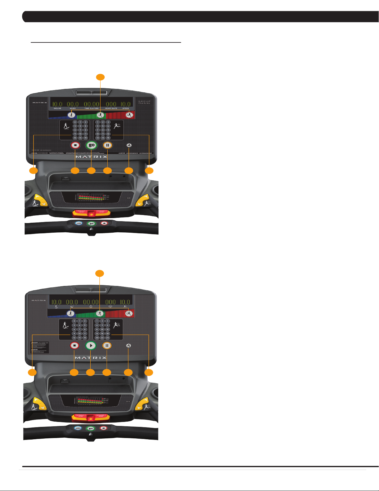
T5X GT CONSOLE DESCR IPTION
The Matrix Machine is inspected before it is packaged. It is shipped in two pieces: the base and
the console. Carefully unpack the unit and dispose of the box material. Note: There is a thin
protective sheet of clear plastic on the overlay of the console that should be removed before use.
The T5xGT treadmill is specifically designed for Group Training settings, with one touch speed
and incline controls for members to follow coaching and make easy changes on the fly.
A) INTENSITY BUTTONS:
Pre-workout - Press to customize your low/medium/high intensity presets.
During workout - Press to automatically adjust speed to your presets.
Note: Default speed/incline presets will be used if not customized pre-workout.
B) ONE-TOUCH INCLINE CONTROL: Adjust incline during workout.
C) ONE-TOUCH SPEED CONTROL: Adjust speed during workout.
D) FAN: Allows for fan speed selection (fan has three operating speeds.)
E) PAUSE: Pauses workout. Pause duration can be set in manager or engineering mode.
F) STOP: Ends workout and shows workout summary data.
G) GO: One Touch Start
NOTE: To access manager mode on the T5xGT console, press and hold the ‘1’ buttons
for speed and incline for 4 seconds. Navigate the menus using handle bar toggles.
5X GT
E
A
D CB F G
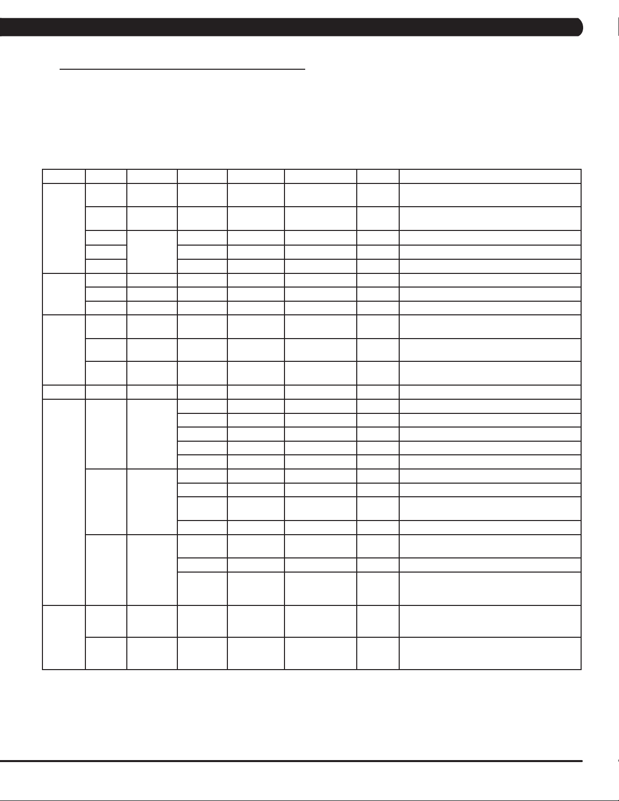
T5X GT CONSOLE DESCR IPTION (METRIC)
The Matrix Machine is inspected before it is packaged. It is shipped in two pieces: the base and
the console. Carefully unpack the unit and dispose of the box material. Note: There is a thin
protective sheet of clear plastic on the overlay of the console that should be removed before use.
The T5xGT treadmill is specifically designed for Group Training settings, with one touch speed
and incline controls for members to follow coaching and make easy changes on the fly.
A) INTENSITY BUTTONS:
Pre-workout - Press to customize your low/medium/high intensity presets.
During workout - Press to automatically adjust speed to your presets.
Note: Default speed/incline presets will be used if not customized pre-workout.
B) ONE-TOUCH INCLINE CONTROL: Adjust incline during workout.
C) ONE-TOUCH SPEED CONTROL: Adjust speed during workout.
D) FAN: Allows for fan speed selection (fan has three operating speeds.)
E) PAUSE: Pauses workout. Pause duration can be set in manager or engineering mode.
F) STOP: Ends workout and shows workout summary data.
G) GO: One Touch Start
NOTE: To access manager mode on the T5xGT console, press and hold the ‘1’ buttons
for speed and incline for 4 seconds. Navigate the menus using handle bar toggles.
E
A
D CB F G
4.1 CONSOLE DESCRIPTION
US
KM
4
Page 7
CHAPTER 5: MANAGER MODE
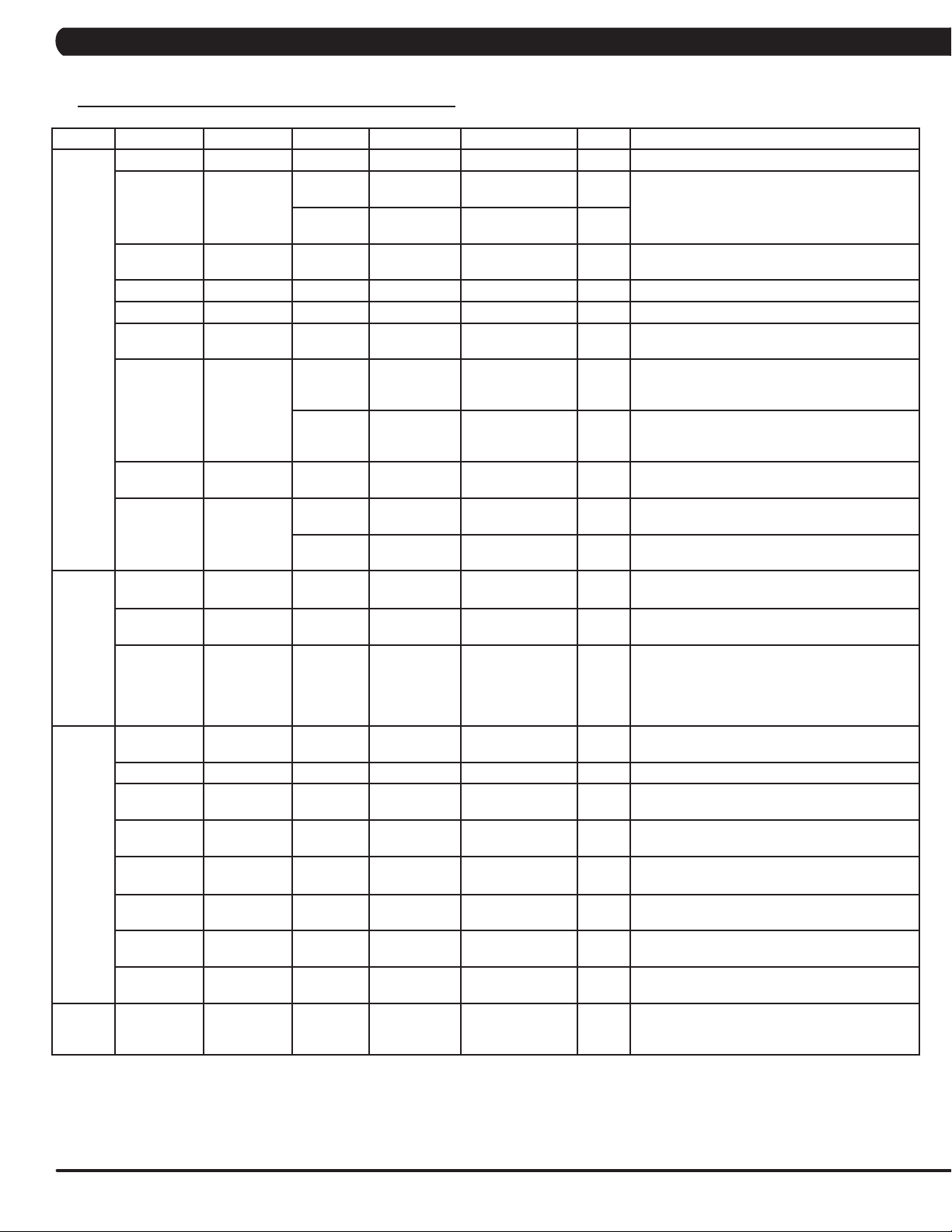
5.1 MANAGER MODE OVERVIEW
1) To enter Manager Mode, press and hold down the Quick Speed 1 and Quick Elevation 1 keys. Continue to hold down these two keys until
the display reads Manager Mode and hit PAUSE key to enter.
2) To scroll through the list of options in Manager Mode, use the quick key Speed UP and Speed DOWN LEVEL keys. Each of the custom settings will show on the display.
3) To select a custom setting, press the PAUSE key when the desired setting is shown.
4) To change the value of the setting, use the quick key Speed UP and Speed DOWN LEVEL keys.
5) To confirm and save the value of the setting, press the PAUSE key.
6) To exit the setting without saving, press the STOP key.
7) Press and hold the STOP key for 3-5 seconds to return to normal operation.
Group Model Item1 Item2 Default Value Values/Range Unit Notes
Workouts T5GT Pause Time 5:00 0:30/1:00/2:00/
T5GT Weight 150lb/
T5GT Workout
T5GT Mid 4.0MPH full speed This option controls the default Mid speed.
T5GT High 5.0MPH full speed This option controls the default High speed.
Date &
Time
Speed T5GT Unit Standard Standard/Metric This option sets the default distance unit: Mile
T5GT Date 2015/01/01 This option sets the current date of the machine.
T5GT Time RTC time This option sets the current time of the machine.
T5GT Time Zone 21 1~78 This option sets the time zone (See Table 1).
T5GT Max. 12.0/20.0 2.0/3.2~15.0/24.1 mph/kph Controls the maximum speed for all programs.
default
Low 3.0MPH full speed This option controls the default low speed.
68kg
3:00/4:00/5:00
50lb/23kg ~
400lb/182kg
Minutes :
Second
This option controls the default pause time.
This option controls the default weight.
or Kilometer".
T5GT Start 0.5/0.8 0.5/0.8~1.4/2.3 mph/kph Controls the starting speed for all programs
Elevation T5GT Max 15%
Software T5GT Version UCB Current software version of UCB.
MCB Current software version of MCB.
Language Sets the language for the console.
WiFi Current software version of WiFi.
Bootloader Current software version of bootloader.
T5GT Update UCB UCB software update.
MCB MCB software update.
LCB-MCUA
(option)
Language Language software update.
T5GT Auto
Update
General T5GT Accumulate
Distance
T5GT Accumulate
Time
Disable/
Enable
Time 1:00 AM HH:MM Automatically software updated time.
Check
Update
Enable This option controls whether the auto software
0 0~999999 Mile/Km Total distance for all programs. Hold UP and
0 0~999999 Hours Total time for all programs displayed in hours.
15% (T)
(does not affect minimum speeds).
Controls the high incline parameter.
LCB-MCUA software update.
update function is Disabled or Enabled.
Manually check remote update. Auto updating
console software from DAPI if it has the latest
version.
DOWN LEVEL keys for 3 seconds to clear
record.
Hold UP and DOWN LEVEL keys for 3 seconds
to clear record.
5
Page 8
CHAPTER 5: MANAGER MODE
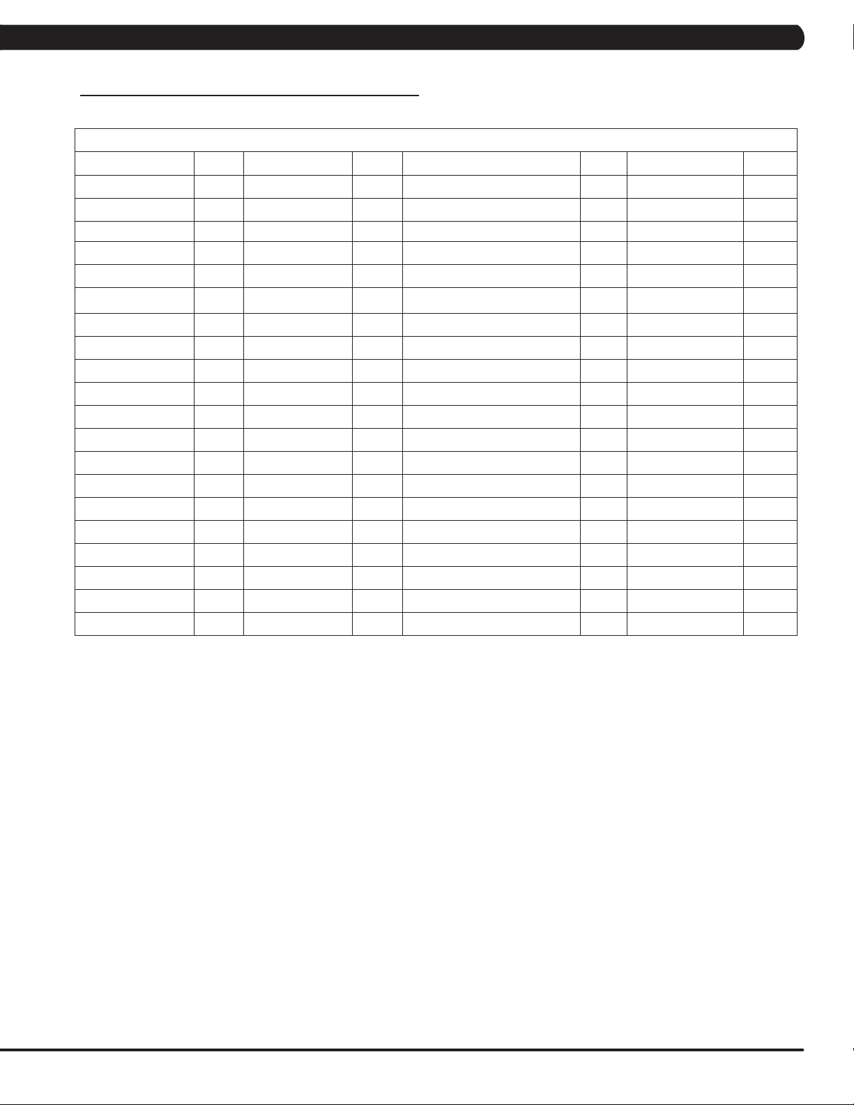
5.1 MANAGER MODE OVERVIEW - CONTINUED
Group Model Item1 Item2 Default Value Values/Range Unit Notes
Machine T5GT Type This option selects the current model.
T5GT Serial
Number
T5GT Out of Order OFF ON/OFF This option allows the club to show the unit "out
T5GT Tread Sensor 30 30/60/90/OFF Tread Sensor function for user’s existence detect.
T5GT Speaker OFF ON/OFF Sets the beeps of the console buttons on/off.
T5GT Beeper ON ON/OFF Sets the beeps that accompany the 3,2,1 before
T5GT Headphone
Jack
T5GT USB Port Protection Enable Enable/Disable This option controls whether the USB port
T5GT Keypad Stuck
TV T5GT Power OFF ON/OFF OFF: Turn off TV power after reset
T5GT Input Source OFF OFF/TV/PCTV/
T5GT Default
Volume
Internet T5GT Enable/
Disable
T5GT MAC ID MAC ID data.
T5GT IP Automatically detects the available IP address
T5GT AP Mode OFF ON/OFF Sets whether the console wireless module is an
T5GT Signal
Strength
T5GT Export setting
to USB
T5GT Import setting
from USB
T5GT Reset Reset internet connected data. SSID/password
ErP T5GT Erp Time OFF OFF~ 30
Console Prefix+(Type)
Frame Prefix+(Type)
Notification Enable Enable/Disable This option controls whether the headphone Jack
Times to
waring
Check
Notification Enable Enable/Disable This option controls whether the Keypad/overlay
+YYMM00000
+YYMM00000
30000 1000~1000000 This option controls whether the headphone Jack
Enable Enable/Disable This option controls whether the keypad stuck
(Current
Status)
YY-MM-xxxxx Serial Number input is available for both the
YY-MM-xxxxx
Remote TV/CAB
Disconnected/25%
/50%/75%/100%
Minute Console will enter ErP mode if user does not
(Minutes)
Console and Frame.
Type: B~Z (A not display).
of order" if an error is present.
the machine starts on/off.
insertion times warning function is disabled or
enabled.
insertion times warning function is disabled or
enabled.
protection is disabled or enabled.
check is disabled or enabled.
error notification is disabled or enabled.
ON: Don't turn off TV power after reset
Sets the audio of the console to the type of TV
attached.
a. input default (DF: 15/Range1~15)
b. Max (DF: 32/ Range: 1~32)
c. Output Default (DF: 13/Range:1~Max)
Remote TV support a/b/c item, others only
support c.
Sets whether the internet function (WiFi) is
disabled or enabled.
and displays it.
access point (AP) or not.
This option shows the current WiFi signal
strength.
Export internet setting (WiFi) to USB.
Import internet (WiFi) setting from USB.
Factory Default Restore.
touch the screen or press any key pad for couple
minutes.
6
Page 9
CHAPTER 5: MANAGER MODE
5.1 MANAGER MODE OVERVIEW - CONTINUED
Table 1 - Time Zone list
Time Zone
Country Code Country Code Country Code Country Code
Asia/Kabul 1 America/Chicago 21 Asia/Jerusalem 41 Pacific/Apia 61
America/Anchorage 2 America/Monterrey 22 Asia/Seoul 42 Asia/Bangkok 62
Asia/Kuwait 3 Asia/Shanghai 23 Atlantic/South Georgia 43 Asia/Singapore 63
Asia/Muscat 4 Africa/Nairobi 24 America/Denver 44 Africa/Harare 64
Asia/Baghdad 5 Australia/Brisbane 25 America/Chihuahua 45 Asia/Colombo 65
America/Halifax 6 Europe/Minsk 26 Asia/Rangoon 46 Asia/Taipei 66
Australia/Darwin 7 America/Sao Paulo 27 Asia/Novosibirsk 47 Australia/Hobart 67
Australia/Sydney 8 America/New York 28 Africa/Windhoek 48 Asia/Tokyo 68
Asia/Baku 9 Africa/Cairo 29 Asia/Kathmandu 49 Pacific/Tongatapu 69
Atlantic/Azores 10 Asia/Yekaterinburg 30 Pacific/Auckland 50 America/Indianapolis 70
America/Edmonton 11 Pacific/Fiji 31 America/St Johns 51 America/Phoenix 71
Atlantic/Cape Verde 12 Europe/Riga 32 Asia/Irkutsk 52 Asia/Vladivostok 72
Asia/Yerevan 13 Asia/Tbilisi 33 Asia/Krasnoyarsk 53 Australia/Perth 73
Australia/Adelaide 14 Europe/London 34 America/Santiago 54 Africa/Lagos 74
America/Costa Rica 15 America/Godthab 35 America/Tijuana 55 Europe/Berlin 75
Asia/Almaty 16 Africa/Monrovia 36 Europe/Paris 56 Asia/Tashkent 76
America/Cuiaba 17 Europe/Istanbul 37 Europe/Moscow 57 Pacific/Guam 77
Europe/Belgrade 18 Pacific/Honolulu 38 America/Argentina/Buenos Aires 58 Asia/Yakutsk 78
Europe/Belgrade 19 Asia/Calcutta 39 America/Bogota 59
Pacific/Guadalcanal 20 Asia/Tehran 40 America/La Paz 60
7
Page 10
CHAPTER 6: ENGINEERING MODE
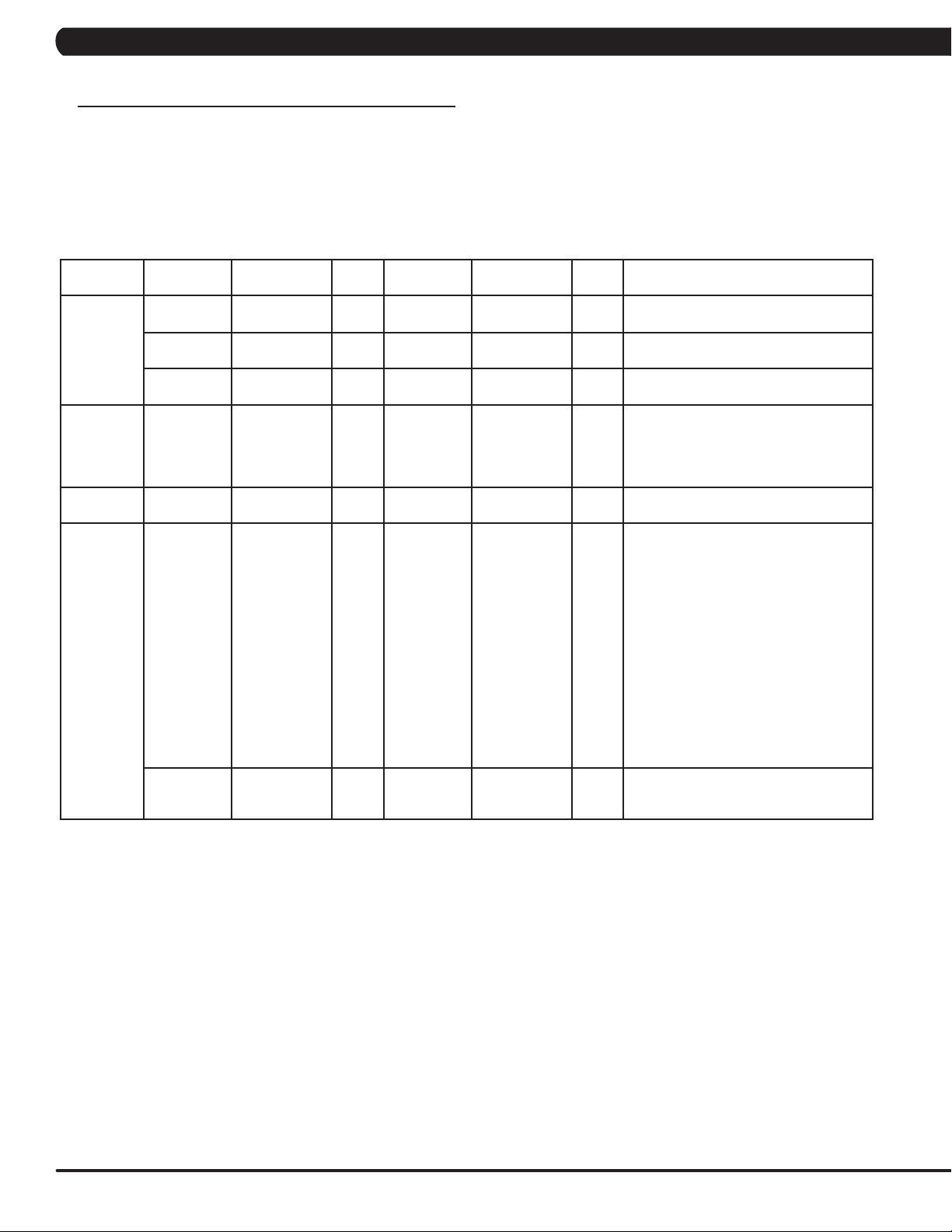
6.1 ENGINEERING MODE OVERVIEW
1) To enter Manager Mode, press and hold down the Quick Speed 2 and Quick Elevation 2 keys. Continue to hold down these two keys until
the display reads Manager Mode and hit PAUSE key to enter.
2) To scroll through the list of options in Manager Mode, use the quick key Speed UP and Speed DOWN LEVEL keys. Each of the custom settings will show on the display.
3) To select a custom setting, press the PAUSE key when the desired setting is shown.
4) To change the value of the setting, use the quick key Speed UP and Speed DOWN LEVEL keys.
5) To confirm and save the value of the setting, press the PAUSE key.
6) To exit the setting without saving, press the STOP key.
7) Press and hold the STOP key for 3-5 seconds to return to normal operation.
Group Model Item1 Item2 Default Value Values/Range Unit Notes
Calibration T5GT Auto
T5GT Elevation Min This option controls the minimum elevation
T5GT Elevation Max This option controls the maximum
Running
Test
Error Codes T5GT Disable/Enable Enable Disable/Enable This option displays the error code history
DAPI T5GT Server Production Dev/
T5GT This option allows installers to do the belt
T5GT SSL ON ON/OFF This option controls whether the internet
Calibration
QA/
Staging/
Production
This option is to calibrate the elevation
parameters.
parameter.
elevation parameter.
adjustment and test. Also this function will
not stop until press Stop or
exit the mode, it will provide customer for
demonstration and other functions.
on the unit.
Dev
unsecure domain: dev.dls.jfit.co port: 80
SSL domain: dev-dls.jfit.co port: 443
QA
unsecure domain: qa.dls.jfit.co port: 80
SSL domain: qa-dls.jfit.co port 443
Staging
unsecure domain: staging.dls.jfit.co port:
80
SSL domain: staging-dls.jfit.co port 443
Production
unsecure domain: dapi-ls.jfit.co port: 80
SSL domain: dapi-ls.jfit.co port: 443
transmission with SSL (Secure Sockets
Layer) or not.
8
Page 11
CHAPTER 7: SERVICE MODE/TEST MODE
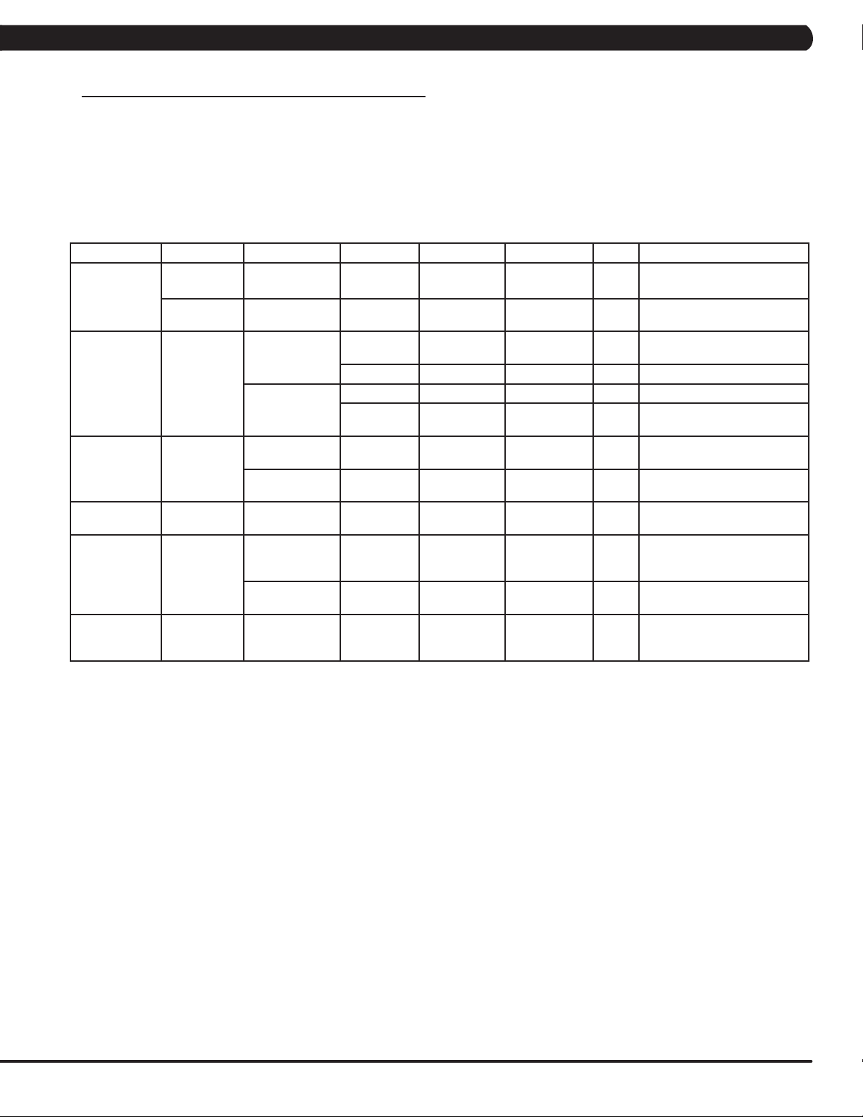
7.1 SERVICE MODE OVERVIEW
1) To enter Manager Mode, press and hold down the Quick Speed 3 and Quick Elevation 3 keys. Continue to hold down these two keys until
the display reads Manager Mode and hit PAUSE key to enter.
2) To scroll through the list of options in Manager Mode, use the quick key Speed UP and Speed DOWN LEVEL keys. Each of the custom settings will show on the display.
3) To select a custom setting, press the PAUSE key when the desired setting is shown.
4) To change the value of the setting, use the quick key Speed UP and Speed DOWN LEVEL keys.
5) To confirm and save the value of the setting, press the PAUSE key.
6) To exit the setting without saving, press the STOP key.
7) Press and hold the STOP key for 3-5 seconds to return to normal operation.
Group Model Item1 Item2 Default Value Values/Range Unit Notes
Accumulate T5GT Distance Current value 0~999999 Mile/KmManually sets the Accumulated
T5GT Time Current value 0~999999 Hour Manually sets the Accumulated
Log T5GT Error Display Error1~Error10
Reset NO NO-YES Reset error log..
Headphone Jack
Sensor
Configuration T5GT Export to USB Export engineer parameters to
Import from USB Import engineer parameters
Factory Default T5GT Reset NO NO-YES Reset engineering default
Asset
management
xID Login T5GT Enable/Disable Disable Disable/Enable
T5GT Disable/Enable Disable Disable/Enable
Club ID This option records the club ID
Insert Counts Current Value 0~999999 Insert headphone jack counts..
Reset NO NO-YES Reset headphone insert
/ None
Distance.
Time.
Shows the last 10 errors.
counts.
a USB device.
from a USB device.
to factory value.
This option controls whether
the AM function is Disabled or
Enabled.
of the fitness facility.
This option controls whether
the xID login function is
Disabled or Enabled.
9
Page 12
CHAPTER 7: SERVICE MODE/TEST MODE
7.2 TEST MODE OVERVIEW
1) To enter Manager Mode, press and hold down the Quick Speed 5 and Quick Elevation 5 keys. Continue to hold down these two keys until
the display reads Manager Mode and hit PAUSE key to enter.
2) To scroll through the list of options in Manager Mode, use the quick key Speed UP and Speed DOWN LEVEL keys. Each of the custom settings will show on the display.
3) To select a custom setting, press the PAUSE key when the desired setting is shown.
4) To change the value of the setting, use the quick key Speed UP and Speed DOWN LEVEL keys.
5) To confirm and save the value of the setting, press the PAUSE key.
6) To exit the setting without saving, press the STOP key.
7) Press and hold the STOP key for 3-5 seconds to return to normal operation.
Group Model Item1 Item2 Default
Value
Display T5GT Press the ENTER key repeatedly to
Keypad T5GT Press any key and the display should
C-SAFE T5GT Press the ENTER key to test CSAFE.
Headphone Jack T5GT Press the ENTER key to test the insert
RFID Test T5GT Press the ENTER key to test RFID
ErP T5GT Auto/5/10/30/60 Second Press the ENTER key and choice ErP
Values/
Range
Unit Notes
check each set of LEDs on the display
sequentially.
show the corresponding message.
headphone jack counts.
hardware and RFID card scan.
time to test ErP function.
10
Page 13
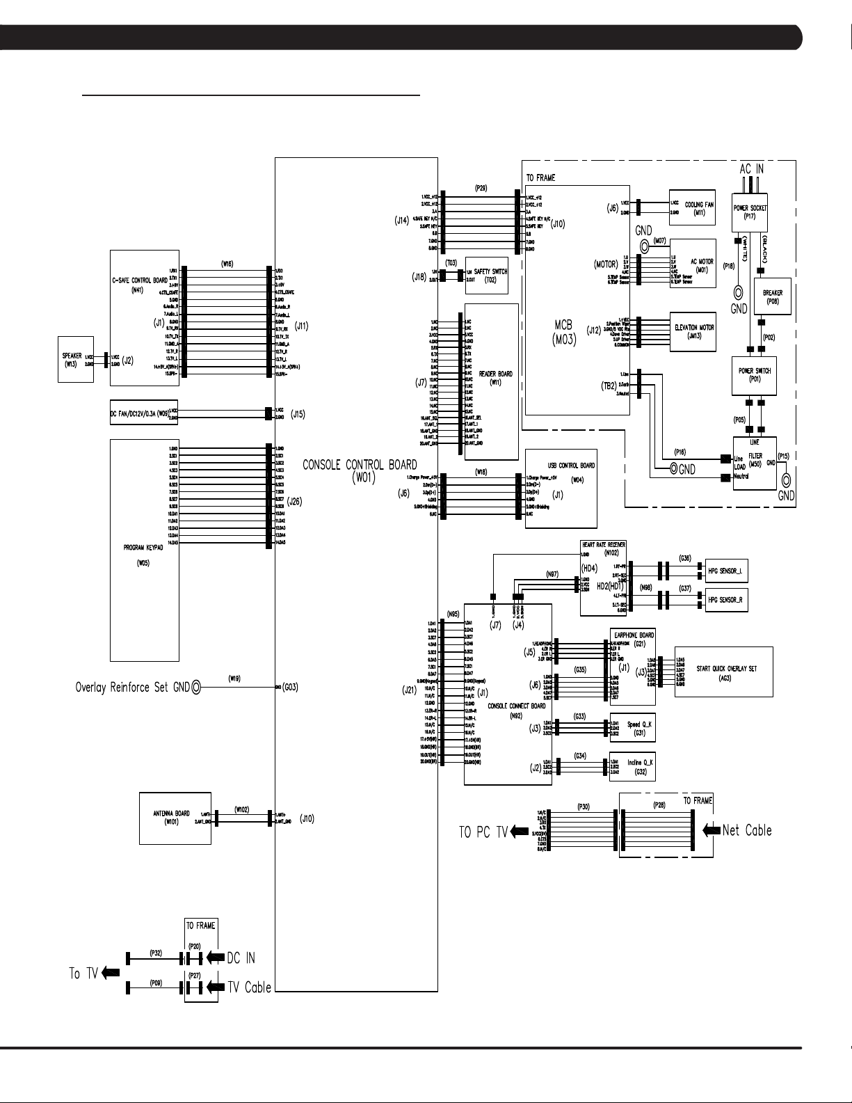
8.1 ELECTRICAL DIAGRAMS
ELECTRICAL BLOCK DIAGRAM
CHAPTER 8: TROUBLESHOOTING
11
Page 14
CHAPTER 8: TROUBLESHOOTING
8.1 ELECTRICAL DIAGRAMS - CONTINUED
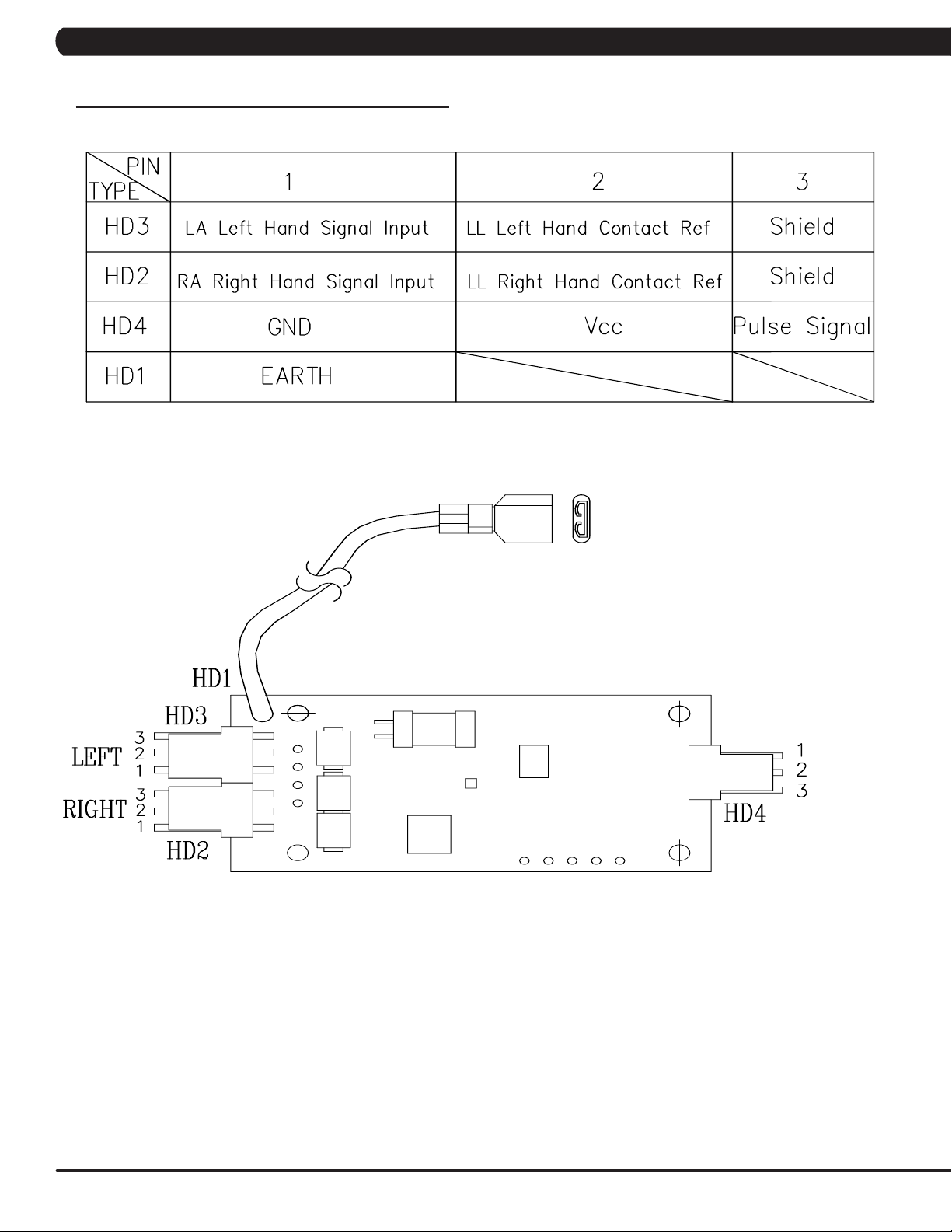
PLUSE BOARD SET
12
Page 15
CHAPTER 8: TROUBLESHOOTING
8.1 ELECTRICAL DIAGRAMS - CONTINUED
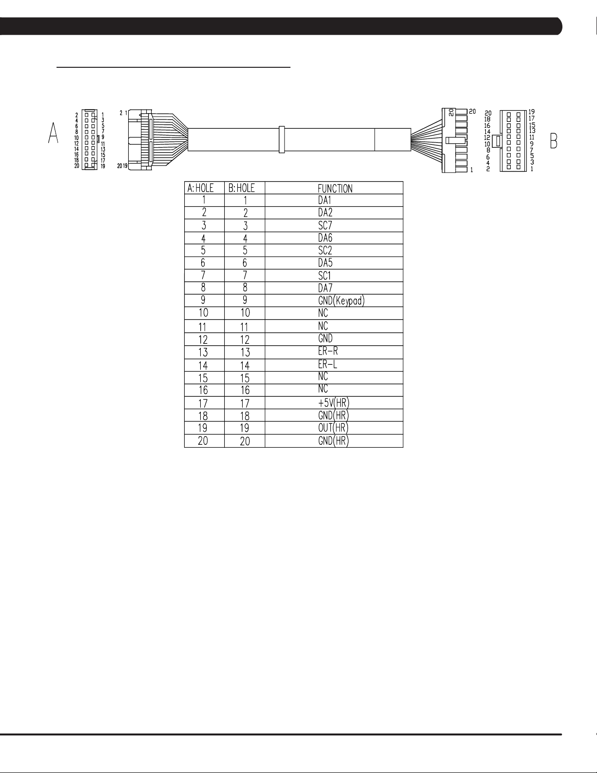
UCB LITTLE BOARD WIRE
13
Page 16
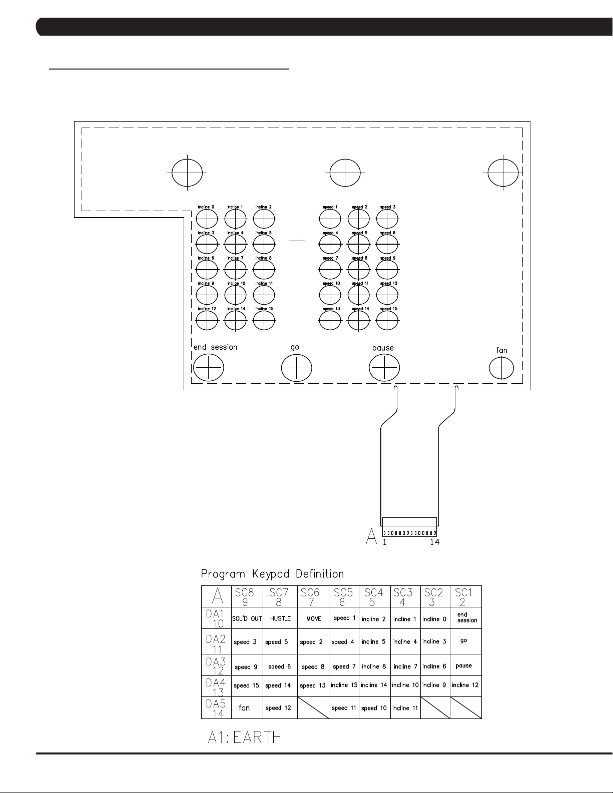
CHAPTER 8: TROUBLESHOOTING
8.1 ELECTRICAL DIAGRAMS - CONTINUED
PROGRAM KEYPAD
14
Page 17

CHAPTER 8: TROUBLESHOOTING
8.1 ELECTRICAL DIAGRAMS - CONTINUED
HAND PLUSE SENSOR WIRE
SAFETY SWITCH WIRE
USB WIRE
15
Page 18

CHAPTER 8: TROUBLESHOOTING
8.2 ERROR CODES LIST
01XX: Motor Errors
CODE CLASS DESCRIPTION MACHINE SOLUTION
0140 B
0142
(01A2)
0144 B Motor over current T
0147
(01A0)
01A1 C
01A3 C
01A8 C
01AD
(0141)
Incline motor operation fail
Incline motor is
detected in the
B
reverse of the
position indicated by
the potentiometer.
Incline motor dis-
B
connection
Incline calibration
error
Main motor disconnection
Main motor over
current
Motor over tem-
B
perature
T
T
T
T
T
T
T
Please run Auto Calibration.
- If the error code happens in Auto-calibration, the machine still can work and no
repairs are needed.
- If the error code happens in workout, please replace the incline motor.
a. Check the connection of the incline motor cable at the MCB.
b. Run auto calibration.
c. If auto calibration fails, re-enter Engineering Mode and go to Calibration again.
- Select Calibration key.
- Check the MCB LEDs. If LED DOWN or UP has no light, check the console cable
connections at the console and MCB.
Replace the console or cable as needed. If LED DOWN or UP has a light, replace the
incline motor.
d. If the issue is not solved by replacing the incline motor, replace the MCB.
a. Check the condition of the running deck and belt. Replace the belt and flip or
replace the running deck as needed.
b. Replace the MCB.
a. Check the incline motor wire connection between the incline and LCB.
b. Check to see if incline value changes on display when up/down keys are pressed
(pins 1 & 2 for VR1 & VR2, pins 2 & 3 for VR2 & VR3).
- If there’s no change, replace the incline motor.
- If there’s a change, replace the LCB.
a. It occurs when the calibration time is too long or the calibration distance is too
short.
b. Disconnect the incline tube from the frame. Turn on power and run auto calibration.
- If console still shows error, replace incline motor.
- If no error, reattach incline motor, and replace MCB.
a. Check the connection of the motor cable at the MCB.
b. Using a multimeter, check the 3 points (U/V/W) and see if there’s a resistance
reading (pins 1 & 2 for U & V, pins 2 & 3 for V & W, pins 1 & 3 for U & W).
- If yes, replace MCB.
- If no, replace motor (a short or open circuiting).
a. Check the condition of the running deck and belt. Replace the belt and flip or
replace the running deck as needed.
b. Replace the MCB.
a. Check the connection of the motor cable at the MCB.
b. Use a multi-meter to check the motor wire circuit. Set the multi-meter to Ohms and
place both terminals on the blue wires of the motor cable.
- If there is an Ohm reading above 0, replace the motor.
- If the Ohm reading is 0, replace the MCB.
16
Page 19

CHAPTER 8: TROUBLESHOOTING
8.2 ERROR CODES LIST
02XX: MCB Errors
CODE CLASS DESCRIPTION MACHINE SOLUTION
0247
(02BA/
02B9)
02A2 C
02A3 C
02A7 C
B
The inner memory IC data read
/ write error.
Over DC bus
voltage
Low AC power
input voltage
when motor running
Motor over current
T
T
T
T
a. Check LED DSP1 (MCU) on the MCB.
b. If this LED is blinking, replace the console.
c. If this LED is a constant light, replace the MCB.
d. If this LED is not lit at all, check the power to the MCB.
a. Please check if the input power is normal (110V : over 140V or 220V: over 280V).
b. Replace the MCB.
a. Please check if the input power is normal (110V : low 76V or 220V: low 186V).
b. Replace the MCB.
a. Please check the Motor wire connection between the Motor and MCB.
b. Please use the electric meter to check the 3 points (U / V / W) and see if there’s
data of inside impedance (pins 1 & 2 for U & V, pins 2 & 3 for V & W, pins 1 & 3 for U
& W).
- If yes, replace MCB.
- If no, replace Motor set.
02AD C
02BA C
02BB C
02BC C
02BD C
02B2 C
02B5 C
02B6 C
02B7 C
02B8 C
MCB is over
temperature
The inner memory IC data read
error.
Inverter hardware interrupts
error.
Ground connection or fuse error
Drive hardware
interrupt error.
Safe key action
response
Inverter sensor
the normal rated
current over
150% , can hold
60 sec.
Speed up has
over current.
Speed down
has overcurrent.
Running status
is over current
T
T Reboot power. If the error shows again, replace the MCB.
T Reboot power. If the error shows again, replace the MCB.
T
T Replace MCB.
T
T Replace MCB.
T
T
T
a. Check if that both fans are operating (there is a fan mounted to the MCB itself as
well as an external fan). Also check the connection of the fans at the MCB.
b. If the fans are running correctly, replace the MCB.
a. Check the Motor wire (3 points U / V / W) and ground wire whether short.
b. Replace the MCB.
a. Check the connection of the safety key (emergency stop) switch. If the switch is
always open or shorted out, replace the switch.
b. If the emergency stop does not resolve the issue, replace the console.
a. Check the condition of the running deck and belt. Replace the belt and flip or
replace the running deck as needed.
b. Replace the MCB.
a. Check the condition of the running deck and belt. Replace the belt and flip or
replace the running deck as needed.
b. Replace the MCB.
a. Check the condition of the running deck and belt. Replace the belt and flip or
replace the running deck as needed.
b. Replace the MCB.
17
Page 20

CHAPTER 8: TROUBLESHOOTING
8.2 ERROR CODES LIST - CONTINUED
03XX: UCB Errors
CODE CLASS DESCRIPTION MACHINE SOLUTION
0301 A Memory block damage Console
0302 A UCB low battery voltage Console
0303 A UCB low supply voltage Console
0304 A
0305 A
0306 A
0340 B
0341 B Fan over current Console
0343 B UCB Over supply voltage Console
0345 B
0346 B
0347
(03A7)
0348
(03A9)
Earphone Board needs
to be replaced
USB Hardware OT or
OC
keypad is abnormal. The
keypad remains pressed
for 60 seconds
keypad is abnormal. The
keypad remains pressed
for 5 seconds
Correct packet but LCB
without the function
UCB detect the error of
LCB incline position error
B VA Load program fail Console
B Motor does not to run Console
Console
Console
Console
Console
Console
Console
a. Enter the Engineer mode disable B Level Error, bypass CLASS A and B error code.
b. Replace UCB.
a. Enter the Engineer mode disable B Level Error, bypass CLASS A and B error code.
b. Replace battery.
a. Enter the Engineer mode disable B Level Error, bypass CLASS A and B error code.
b. Make sure the RPM over 35, when the machine of self-power mode.
a. Enter the Engineer mode disable B Level Error, bypass CLASS A and B error code.
b. Replace Earphone Board.
a. Enter the Engineer mode disable B Level Error, bypass CLASS A and B error code.
b. Replace UCB.
a. Enter the Engineer mode disable B Level Error, bypass CLASS A and B error code.
b. Replace Keypad.
a. Enter the Engineer mode disable B Level Error, bypass CLASS A and B error code.
b. Replace Keypad.
a. Enter the Engineer mode disable B Level Error, bypass CLASS A and B error code.
b. Replace Fan.
a. Enter the Engineer mode disable B Level Error, bypass CLASS A and B error code.
b. Check whether the LCB power input is over 13 voltage.
- If yes, replace MCB.
- If not, replace UCB.
a. Enter the Engineer mode disable B Level Error, bypass CLASS A and B error code.
b. Replace UCB
a. Enter the Engineer mode disable B Level Error, bypass CLASS A and B error code.
b. Running the incline motor calibration again.
a. Enter the Engineer mode disable B Level Error, bypass CLASS A and B error code.
b. Replace VA Micro SD card
a. Enter the Engineer mode disable B Level Error, bypass CLASS A and B error code.
b. Replace UCB
03A5 C Failed to load program Console Replace UCB.
03A6 C Failed to run program Console Replace UCB.
03A8 C Machine type error All Choose the correct machine type in the console and reboot power again.
A NOTE ON CLASS A AND B ERROR CODES
Some errors can be bypassed in Engineering Mode in order to keep the machine in use.
˙ “Ignore B Level Errors” will bypass class A and B error codes.
˙ “Ignore Incline Errors” will bypass all incline errors.
18
Page 21

CHAPTER 8: TROUBLESHOOTING
8.2 ERROR CODES LIST
04XX: Communication Errors
CODE CLASS DESCRIPTION MACHINE SOLUTION
0440 B
0441 B
0442 B
04A0 C
04B0 C
04B1 C
Timeout receive
packet
When UCB implements a command,
but the LCB/MCB
cannot execute the
command
The received command code from the
console is correct
and is supported,
but the data sent/
transferred is wrong
MCB does not have
communication
response from UCB
UCB does not have
communication
response from MCB
IO board does not
have communication
response
Communication
Errors
Communication
Errors
Communication
Errors
Communication
Errors
Communication
Errors
Communication
Errors
a. Enter the Engineer mode disable B Level Error, bypass CLASS A and B error code.
b. Check the connection of the console cable at both ends and perform continuity test.
c. Replace MCB.
Enter the Engineer mode disable B Level Error, bypass CLASS A and B error code.
Enter the Engineer mode disable B Level Error, bypass CLASS A and B error code.
Delta MCB only:
a. If the display is giving an 04A0 error, LED DSP2 (RS485) should be off. Recycle
power..
b. Check the connection of the console cable at both ends and perform continuity test.
c. Swap console with known good if connections are good. Replace the console.
d. Replace the MCB.
Delta MCB only:
a. If the display is giving an 04A0 error, LED DSP2 (RS485) should be off. Recycle
power..
b. Check the connection of the console cable at both ends and perform continuity test.
c. Swap MCB with known good if connections are good. Replace the MCB.
d. Replace the console.
a. Replace UCB.
19
Page 22

CHAPTER 9: PARTS REPLACEMENT GUIDE
9.1 CONSOLE REPLACEMENT
1) Turn off power and disconnect the cord from the machine.
2) Remove the back cover of the console (Figure A).
3) Disconnect the console cable connectors (Figure B).
FIGURE A
4) Remove the six 6 mm screws from underneath the console. There are arrows stamped in the plastic at the proper openings (Figure C).
5) Move the console away from the console frame (Figure D).
6) Reverse Steps 1-5 to install a new console.
FIGURE B
FIGURE C FIGURE D
20
7) Auto Calibration must ALWAYS be run after replacing the console (see Section 3.3).
Page 23

CHAPTER 10: SPECIFICATIONS AND ASSEMBLY GUIDE
10.1 WIFI INSTALLATION
HURESACT5X WIFI Installation
MAIN COMPONENT LIST OF WIFI SET (PART NUMBER #1000366472)
Item Parts number Description Q’ty
1 1000385415 Control Board;;;HF-A11-0;V2.049;;; 1
1.1 1000385417 Control Board;;;V5.0;V2.049;;HF-A11-0; 1
1.2 1000385418
1.3 1000385725 Foam Tap;;;41x11;;3M 4945; 1
2 0000086721 SCREW;RND;M2X0.5PX6L;;PH;;BZN;; 2
3 1000309516 Tape;;;40x10x0.2;;EP614 1
WIFI Aerial;;;;;NB098-2400300PEX;;HF-A1
1
21
Page 24

CHAPTER 10: SPECIFICATIONS AND ASSEMBLY GUIDE
10.1 WIFI INSTALLATION - CONTINUED
10.1.2 T5X WIFI Installation
1) Plug in the WiFi board (item #1.1 in the table) to the UCB and use the 2 screws (item #2 in the table) to fix it (Figure A).
2) Stick the foam tape (item #1.3 in the table) on the front cover (Figure B).
FIGURE A FIGURE B
3) Stick the WiFi aerial board (item #1.2 in the table) to foam tape and connect the signal wire to WiFi board (Figure C).
4) Use tape (item #3 in the table) to fix the signal connecting wire to the front cover of the console (Figure D).
FIGURE C
FIGURE D
22
Page 25

CHAPTER 10: SPECIFICATIONS AND ASSEMBLY GUIDE
10.1 WIFI INSTALLATION - CONTINUED
10.1.3 How to set up the “WIFI” function
1. Create a WiFi config file
Step 1: Use your computer and use "note" function to create a wifi config file (the name is called 'wifi_set.cfg’ - Figure A).
Step 2: Check your AP data and modifying SSID & Key (password) required by facility Access Point (AP) to 'wifi_set.cfg' files. Once this is
completed, put the 'wifi_set.cfg' file to USB flash drive (the access should read \MATRIX\FW\ - Figure B).
FIGURE BFIGURE A
2. Install WiFi config software for WiFi connection.
Step 1: Insert USB driver with ‘wifi_set.cfg’ file to console (Figure C).
Step 2: Enter Manager Mode by pressing and holding down the Quick Speed 1 and Quick Elevation 1 keys.
Step 3: Use the quick key Speed UP and Speed DOWN LEVEL keys to select “Internet” and press PAUSE Key to enter (Figure D).
FIGURE DFIGURE C
Step 4: Pres the PAUSE key to enter Enable/Disable setup (Figure E).
Step 5: Use the quick key Speed UP and Speed DOWN LEVEL keys to select to select "Enable" and press PAUSE Key to save (Figure F).
FIGURE FFIGURE E
23
Page 26

CHAPTER 10: SPECIFICATIONS AND ASSEMBLY GUIDE
10.1 WIFI INSTALLATION - CONTINUED
10.1.3 How to set up the “WIFI” function - continued
3. Install WiFi config software for WiFi connection - continued
Step 6: Press the stop key on the number keypad to back. Use the quick key Speed UP and Speed DOWN LEVEL keys to select "Import
Setting" (Figure G).
Step 7: Press the pause key to start wifi installation process (Figure H).
FIGURE HFIGURE G
Step 8: When the message shows “Success !!" in a short time, it means the update is complete (Figure I).
FIGURE I
4. Console WiFi function test
Step 1: Enter Manager mode -> Internet -> MAC ID (Figure A).
Step 2: If WiFi Module was installed correctly, the screen will show the MAC ID data (Figure B).
24
FIGURE BFIGURE A
Page 27

CHAPTER 10: SPECIFICATIONS AND ASSEMBLY GUIDE
10.1 WIFI INSTALLATION - CONTINUED
10.1.3 How to set up the “WIFI” function - continued
4. Console WiFi function test - continued
Step 3: Enter Manager mode -> Internet -> Signal Strength (Figure C). See if the wireless signal strength is OK (Figure D).
Note: For wireless connection quality, it is necessary to have a stable wireless signal.
FIGURE DFIGURE C
Step 4: Enter Manager mode -> Internet -> IP (Figure E).
Step 5: If WiFi module was connected with AP, the screen will show the IP address (Figure F).
FIGURE FFIGURE E
25
Page 28
CHAPTER 10: SPECIFICATIONS AND ASSEMBLY GUIDE
10.1 WIFI INSTALLATION - CONTINUED
10.1.3 How to set up the “WIFI” function - continued
4. Console WiFi function test - continued
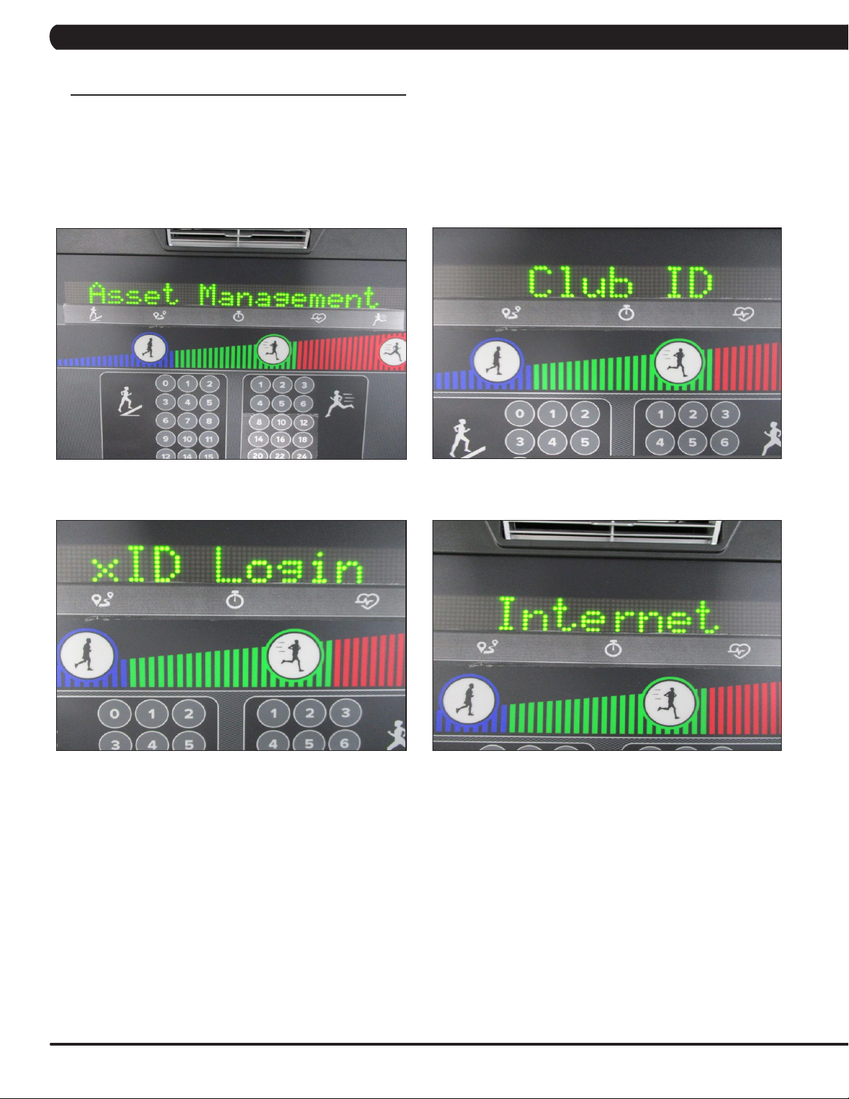
Step 6: From the home screen on the console, press and hold down the Quick Speed 3 and Quick Elevation 3 keys to go to Service Mode.
Select Asset Management setting is “Enable” (Figure G) and edit Club ID (Figure H). Verify and setup the xID Login setting is “Enable” too
(Figure I). press and hold down the Quick Speed 1 and Quick Elevation 1 keys to go to Manager Mode, verify and setup the Internet setting is
“Enable” (Figure J).
FIGURE HFIGURE G
FIGURE JFIGURE I
26
Page 29

CHAPTER 10: SPECIFICATIONS AND ASSEMBLY GUIDE
10.2 RFID INSTALLATION
10.2.2 T5X RFID Installation
NOTE: To use the RFID function on the T5x console, you must order and install the Wi-Fi set (part number
#1000366472, see section 10.1) and RFID set (part number #1000364291) at the same time. The SAP # for
the WIFI + RFID kit is 1000390648.
WIFI + RFID kit SAP no.
Item Parts number Description
1 1000366472 Wi-Fi set
1000390648
2 1000364291 RFID set
MAIN COMPONENT LIST OF RFID SET (PART NUMBER #1000364291)
Including kit
Item Parts number Description Q’ ty
1 1000355790 Reader;;;GAT-RM310 3.0;V3.1.1.0/V1.2;;EP 1
2 004350-AB SCREW;BH;M3X0.5PX6L;;PH;;;;BP 2
3 1000355791 Antenna board;;;GAT-MAXI LA 3.0;;;EP614C; 1
4 1000364547 Ferrite Plate Absorber;;K5B,FT 10x1.0x10 1
5 1000204284 TAPE;FOAM;SINGLESIDE;15x30x4T; 2
6 1000364292 Signal CONN;;;;;;;500(IPEX,MHF37+JST,ZHR 1
7 1000309516 Tape;;;40x10x0.2;;EP614
8 1000356734 Fixing Bracket;;;PA746;BL/Black C;;TM521
9 008864-A Screw;Round Head;Φ2.9x1.06Px7L;Hi/Lo Thr 3
4
1
27
Page 30

CHAPTER 10: SPECIFICATIONS AND ASSEMBLY GUIDE
10.2 RFID INSTALLATION - CONTINUED
10.2.2 T5x RFID Installation (continued)
1. Stick the foam tape (item #5 in the table) on the UCB in the location that is marked in yellow (Figure A).
FIGURE A
2. Stick the absorber (item #4 in the table) on the reader board in the location that is marked in yellow (Figure B).
3. Plug in the Reader board to the UCB and use the 2 screws (item #2 in the table) to fix it (Figure C).
28
FIGURE CFIGURE B
4. Put the antenna board on the front cover of the console. Connect the signal connecting wire (item #3/6 in the table) to antenna board (Figure
D).
5. Put the fixing bracket (item #8 in the table) on the antenna board. Use the three screws to fix it (Figure E).
FIGURE D
FIGURE E
Page 31

CHAPTER 10: SPECIFICATIONS AND ASSEMBLY GUIDE
10.2 RFID INSTALLATION - CONTINUED
10.2.2 T5x RFID Installation (continued)
6. Connect the Signal connected wire to J8 of UCB (Figure F).
7. Use tape (item #7 in the table) to fix the signal connecting wire to the front cover of the console (Figure G).
FIGURE GFIGURE F
29
Page 32

CHAPTER 10: SPECIFICATIONS AND ASSEMBLY GUIDE
10.2 RFID INSTALLATION - CONTINUED
10.2.3 How to set up the “RFID” function
Once the RFID set has been installed, the xID function must be enabled first, then RFID can be used.
1. Enable "xID" function
Step 1: Enter Service Mode.
Step 2: Select “xID Login” (Figure A).
Step 3: Select “Enable” (Figure B).
Step 4: Enter Engineering Mode.
Step 5: Select “DAPI” (Figure C).
Step 6: Select “Server” (Figure D).
Step 7: Select “Production” (Figure E).
FIGURE BFIGURE A
FIGURE DFIGURE C
30
FIGURE E
Page 33

CHAPTER 10: SPECIFICATIONS AND ASSEMBLY GUIDE
10.2 RFID INSTALLATION - CONTINUED
10.2.3 How to set up the “RFID” function (continued)
2. RFID hardware function test in Test mode and home screen
In TEST mode:
Step 1: Enter Test Mode.
Step 2: Select “RFID” test (Figure A). Pres PAUSE key to enter RFID card scan (Figure B).
Step 3: Put your wristband near RFID reader (Figure C). The wristband data will show on screen (Figure D).
FIGURE BFIGURE A
FIGURE C
In home screen:
Step 4: At the home screen (Figure E), put your wristband with xID account near RFID reader.
Step 5: When the console shows "Welcome", the RFID scan and xID log in was successful (Figure F).
FIGURE D
FIGURE FFIGURE E
31
Page 34

CHAPTER 10: SPECIFICATIONS AND ASSEMBLY GUIDE
10.2 RFID INSTALLATION - CONTINUED
10.2.3 How to set up the “RFID” function (continued)
2. RFID hardware function test in Test mode and home screen - continued
Step 6: Enter Service Mode. Select Asset Management setting “Enable” (Figure G) and edit Club ID (Figure H). Verify the xID Login setting
is set to “Enable” too (Figure I). Enter Manager Mode, verify the Internet setting is set to “Enable” (Figure J).
FIGURE HFIGURE G
32
FIGURE JFIGURE I
Page 35

CHAPTER 10: SPECIFICATIONS AND ASSEMBLY GUIDE
10.3 T5X MYE TV BRACKET INSTALLATION INSTRUCTIONS
The Matrix Treadmill is capable of having a MYE Entertainment or Web Ready (PCTV) television installed using an integrated bracket. Follow
the instructions below to install the MYE TV and TV bracket and Section 10.7 for installation of a PCTV with a bracket, then use the instructions
located in the TV owner's manual to program the TV. NOTE: Both the MYE TV and PCTV use the same bracket kit, which means that there will
be unused wiring depending on which type of TV is being installed.
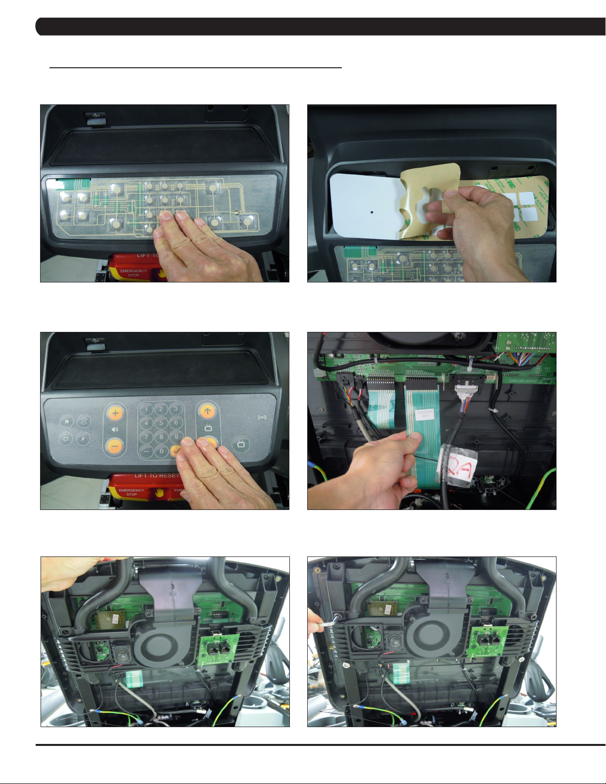
1) Remove the 4 screws holding the console back cover to the front and remove the console back cover (Figures A & B).
FIGURE A FIGURE B
2) Use a razor to remove the heart rate overlay from the lower portion of the console (Figure C).
3) Clean the console area with alcohol to remove any left over adhesive from the overlay (Figure D).
FIGURE C FIGURE D
4) Peel the protective film off of the new entertainment keypad (Figure E).
5) Slide the ribbon cable of the new entertainment keypad through the slot in the console plastic (Figure F).
FIGURE E FIGURE F
33
Page 36
CHAPTER 10: SPECIFICATIONS AND ASSEMBLY GUIDE
10.3 T5X MYE TV BRACKET INSTALLATION INSTRUCTIONS - CONTINUED
6) Stick the keypad to the cutout in the console plastic and press down to completely adhere the keypad to the plastic (Figure G).
7) Peel the protective film from the back of the entertainment overlay (Figure H).
FIGURE G FIGURE H
8) Stick the overlay to the cutout in the console plastic and press down to completely adhere the overlay to the plastic and keypad (Figure I).
9) Plug the keypad ribbon cable into the open pins on the UCB (Figure J). NOTE: Make sure that all pins are engaged by the ribbon cable.
34
FIGURE I FIGURE J
10) Slide the TV bracket between the console frame and the fan frame (Figure K).
11) Secure the TV bracket to the console using the 4 socket head screws sent with the bracket kit (Figure L).
FIGURE K FIGURE L
Page 37

CHAPTER 10: SPECIFICATIONS AND ASSEMBLY GUIDE
10.3 T5X MYE TV BRACKET INSTALLATION INSTRUCTIONS - CONTINUED
12) Attach the coax cable from the TV bracket kit to the coax cable coming up the console mast (Figure M). NOTE: There is an female
adaptor to hook the 2 male coax cable ends together included with the TV bracket kit.
13) Attach the 4 pin black connector side of the power wire to the Mye TV Power port on the UCB (Figure N).
FIGURE M
14) Plug the side of the controller wire marked TO CONSOLE into the TV port of the CSafe board in the console (Figure O).
15) Mount the front plate to the MYE TV using 2 screws sent with the TV bracket kit (Figure P).
FIGURE N
FIGURE O FIGURE P
16) Install the console back cover using the 4 screws removed in Step 1 (Figure Q). NOTE: Make sure to route the wiring through the holes in
the back cover so that none of the wiring is pinched. The MATRIX logo portion of the back cover will not be used with a TV bracket.
17) Plug the coax cable, power wire and controller wire into the MYE TV (Figure R).
FIGURE Q FIGURE R
35
Page 38

CHAPTER 10: SPECIFICATIONS AND ASSEMBLY GUIDE
10.3 T5X MYE TV BRACKET INSTALLATION INSTRUCTIONS - CONTINUED
18) Secure the MYE TV on the TV bracket with 4 screws (Figure S).
19) Make sure the tabs of the front plate slide behind the console faceplate to create a seamless look (Figure T).
FIGURE S
20) A coax cable with a signal strength of 10 Hz should be run to the treadmill and plugged in next to the power cord.
21) Secure the TV back cover to the MYE TV with 4 screws (Figure U).
22) Enter into Manager Mode and set the Input Source setting to TV (Figure V ~ X).
FIGURE T
FIGURE U FIGURE V
36
FIGURE W FIGURE X
23) A channel scan should be done using the instructions included in the TV owner's manual.
Page 39
CHAPTER 10: SPECIFICATIONS AND ASSEMBLY GUIDE
10.4 T5X PCTV BRACKET INSTALLATION INSTRUCTIONS
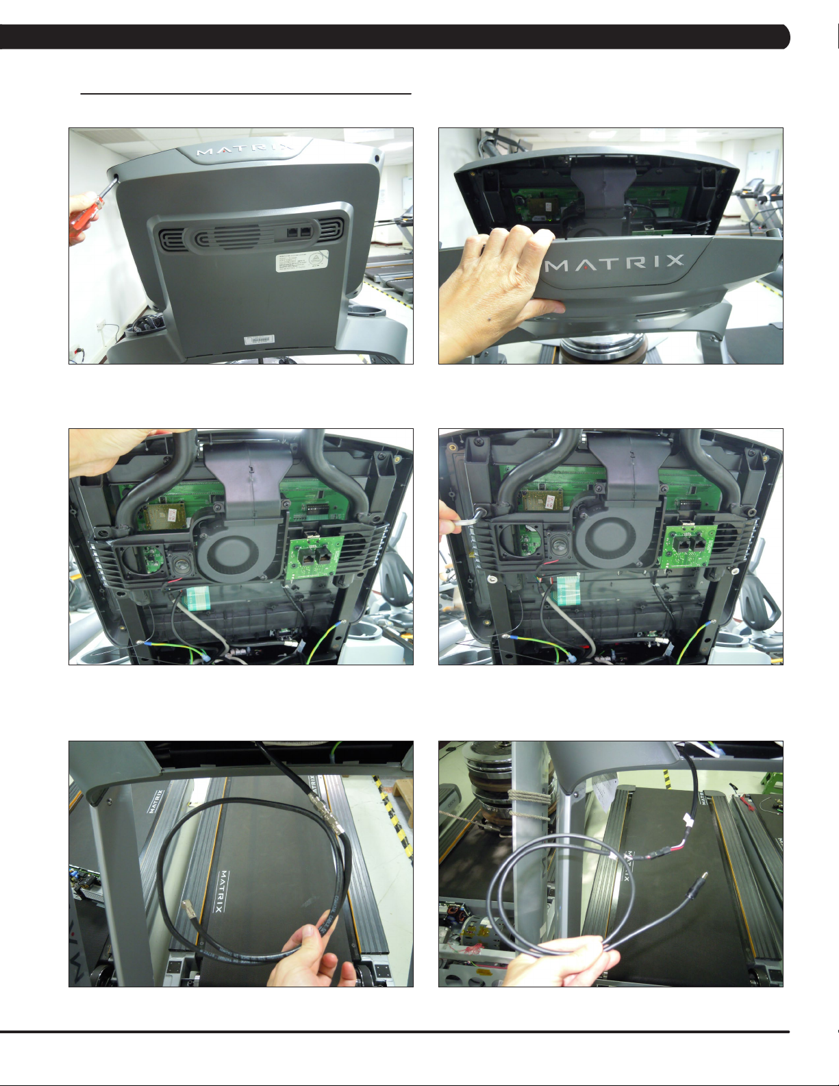
1) Remove the 4 screws holding the console back cover to the front and remove the console back cover (Figures A & B).
FIGURE A FIGURE B
2) Slide the TV bracket between the console frame and the fan frame (Figure C).
3) Secure the TV bracket to the console using the 4 socket head screws sent with the bracket kit (Figure D).
FIGURE C FIGURE D
4) Attach the coax cable from the TV bracket kit to the coax cable coming up the console mast (Figure E). NOTE: There is an adaptor to hook
the 2 male coax cable ends together included with the TV bracket kit.
5) Attach the 4 pin black connector side of the power wire to the TV power wire coming up the console mast (Figure F).
FIGURE E FIGURE F
37
Page 40

CHAPTER 10: SPECIFICATIONS AND ASSEMBLY GUIDE
10.4 T5X PCTV BRACKET INSTALLATION INSTRUCTIONS - CONTINUED
6) Plug the controller wire (this will have a white RJ45 connector on one end) into the UCB and CSafe board (Figure G). NOTE: There is a
wire in this location that will need to be removed to plug in the controller wire.
7) Plug the net wire (this will have a yellow RJ45 connector on one end) into the net wire coming up the console mast (Figure H). NOTE: The
net wire is only needed if wired internet will be used.
FIGURE G FIGURE H
8) Mount the front plate to the PCTV using 2 screws sent with the PCTV bracket kit (Figure I).
9) Plug the coax cable into the port on the PCTV (Figure J).
FIGURE I FIGURE J
10) Plug the TV power wire into the port on the PCTV (Figure K).
11) Plug the controller wire into the port marked PCTV on the PCTV (Figure L).
38
FIGURE K FIGURE L
Page 41

CHAPTER 10: SPECIFICATIONS AND ASSEMBLY GUIDE
10.4 T5X PCTV BRACKET INSTALLATION INSTRUCTIONS - CONTINUED
12) Plug the net wire into the Net port on the PCTV if wired internet will be used (Figure M).
13) If wireless internet will be used, plug the dongle into the port of the PCTV (Figure N), and mount the dongle to the PCTV plastic using
double sided foam tape.
FIGURE M FIGURE N
14) Mount the PCTV to the bracket using 4 screws (Figure O). NOTE: Make sure the tabs of the front plate slide behind the console faceplate
to create a seamless look (Figure P).
FIGURE O FIGURE P
15) Install the console back cover using the 4 screws removed in Step 1 (Figure Q). NOTE: Make sure to route the wiring through the holes in
the back cover so that none of the wiring is pinched (Figure R). The MATRIX logo portion of the back cover will not be used with a TV bracket.
FIGURE Q FIGURE R
39
Page 42

CHAPTER 10: SPECIFICATIONS AND ASSEMBLY GUIDE
10.4 T5X PCTV BRACKET INSTALLATION INSTRUCTIONS - CONTINUED
16) Install the TV back cover using 4 screws (Figure S).
17) Plug the PCTV power wire into the port on the front of the treadmill near the power switch (Figure T).
FIGURE S FIGURE T
18) Plug a coax cable with a signal strength of 10 Hz into the front of the treadmill near the power cord (Figure U).
19) if using wired internet, plug a net wire into the port on the front of the treadmill near the power switch (Figure V).
40
FIGURE U FIGURE V
20) Enter into Manager Mode and set the Input Source to PCTV.
21) A channel scan should be done using the instructions included in the TV owner's manual.
Page 43

CHAPTER 10: SPECIFICATIONS AND ASSEMBLY GUIDE
10.5 RF900/863 RECEIVER INSTALLATION
A. Service Tools & Accessories:
1. Transmitter set (MWT-S8 800MHz or MWT-S9 900MHz) - Figure A
2. Receiver set (MC3R-98; 863MHz/900 MHz) - Figure B
3. Programmer set (MWC5-PRG; 800MHz/900MHz) - Figure C
FIGURE A
FIGURE B
FIGURE C
41
Page 44
CHAPTER 10: SPECIFICATIONS AND ASSEMBLY GUIDE
10.5 RF900/863 RECEIVER INSTALLATION - CONTINUED
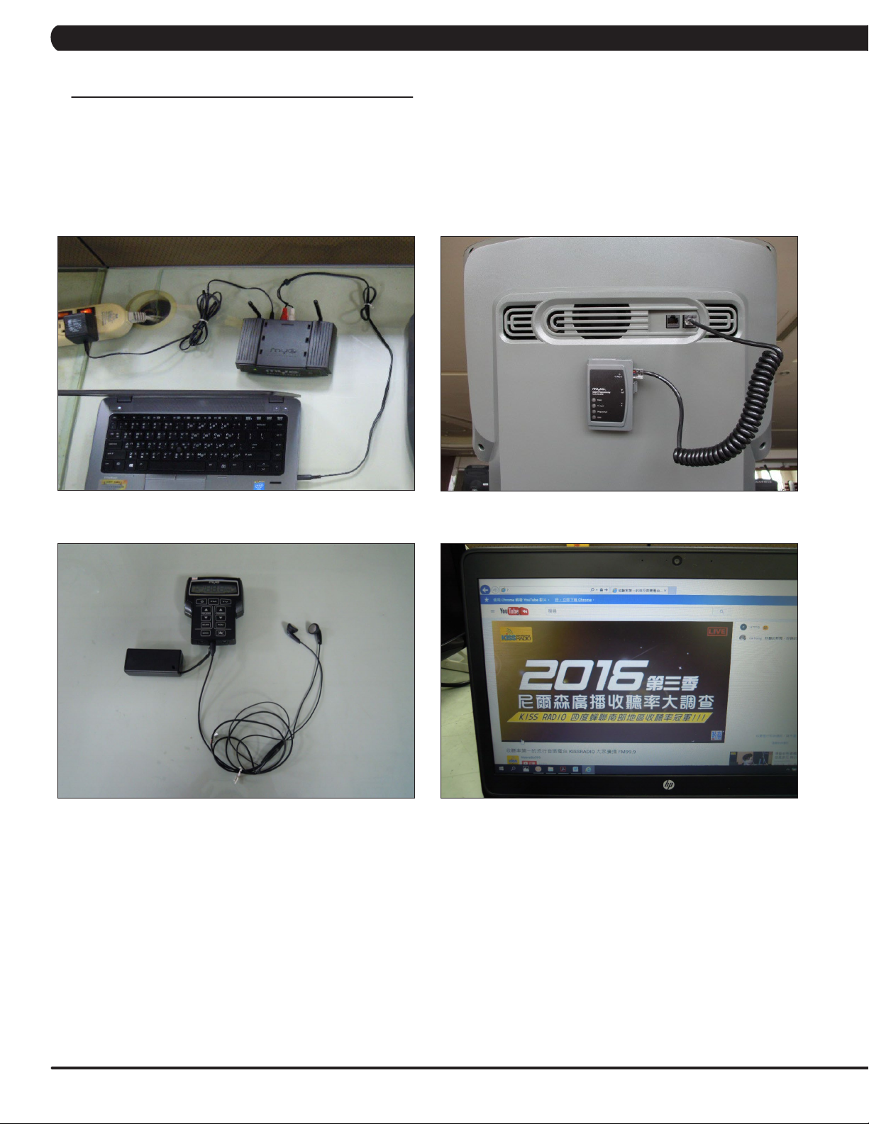
B. 5X RF900/863 Receiver Assembly
1. Connect the Transmitter, TV or other audio sources, receiver, console (Figure A & B). Note: Connect receiver cable to CSAFE port of console
(Figure B).
2. Connect the earphone to Programmer (Figure C).
3. Input audio sources of the TV or PC to Transmitter (Figure D).
FIGURE BFIGURE A
FIGURE DFIGURE C
42
Page 45
CHAPTER 10: SPECIFICATIONS AND ASSEMBLY GUIDE
10.5 RF900/863 RECEIVER INSTALLATION - CONTINUED
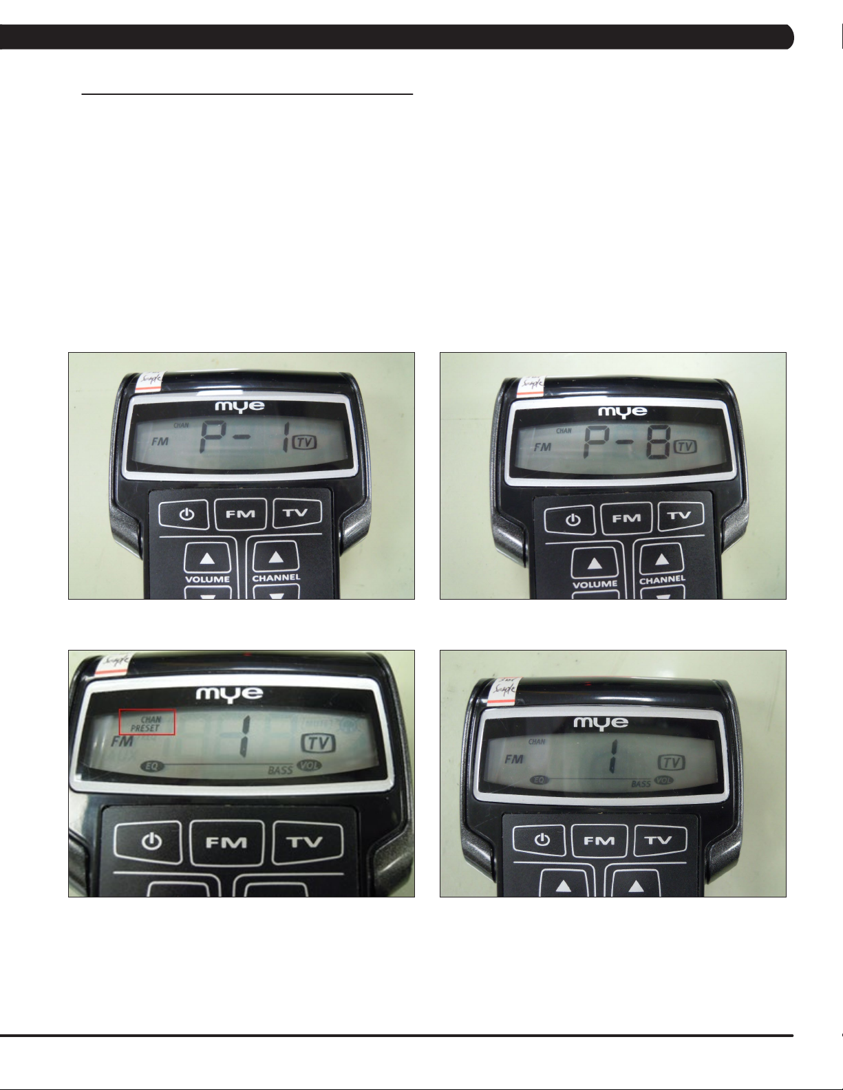
C. Scan Transmitter Channels by Programmer (For details please see MYE operation manual)
1. Press and hold the Channel Down and Volume Up buttons simultaneously for three seconds until "P-1" appears on the display (Figure A).
2. Press the “Ch Up ” button to select one of the following Transmitter Types:
P-1 = MYE Entertainment 900MHz Transmitters (Figure A)
P-8 = Audeon 800MHz Transmitters (Figure B)
3. After selecting the Transmitter type, press the TV button to auto-scan all the frequencies in the transmitter type and lock in transmitters.
4. Hear the sound from programmer. Press CHANNEL UP button to scroll through all transmitter channels.
To add or delete a transmitter channel press the "TV" button. "PRESET" (Figure C) will appear in the display when a transmitter channel is
programmed.
5. To SAVE your presets and exit program mode press the PGM button. The display will blink then default to first transmitter channel
programmed (Figure D).
FIGURE BFIGURE A
FIGURE DFIGURE C
43
Page 46

CHAPTER 10: SPECIFICATIONS AND ASSEMBLY GUIDE
10.5 RF900/863 RECEIVER INSTALLATION - CONTINUED
D. Send a Preset Program from Programmer to a Receiver
The programmer has the ability to CLONE your presets and send the program to any receiver.
1. Confirm your program is saved in the Programmer and is ready to be cloned.
2. Press and hold the SEND and PGM buttons for three seconds until "Snd" appears on the display.
3. Place the IR lens of the programmer six - twelve inches from the IR lens on the Receiver (Figure A).
4. Press the SEND key.
a. Keep the programmer pointed at the receiver.
b. "Snd" will begin flashing on the programmer. The program is being sent.
c. The "Programmed" light will flash on the Smart Receiver. The program is being received.
d. "Snd" and the "Programmed" light will stop flashing when the send is successful. The yellow PROGRAMMED light will stay solid (Figure B)
on the Smart Receiver for 5 seconds then turn off.
e. The TX signal light will appear solid green if a transmitter is detected on the first programmed channel (Figure C). If no TX light appears, no
transmitter is detected.
f. An error code of "E2" will appear on programmer and a RED light will appear next to ERROR on the Smart Receiver if the SEND was
incomplete. Realign the two units and press SEND again.
5. To EXIT "SEND" Mode on the MWC5-PRG press PGM.
44
FIGURE BFIGURE A
FIGURE C
Page 47

CHAPTER 10: SPECIFICATIONS AND ASSEMBLY GUIDE
10.5 RF900/863 RECEIVER INSTALLATION - CONTINUED
E. Console Setup for Audio Receiver
1. To enter Manager Mode, press and hold down the Quick Speed 2 and Quick Elevation 2 keys, and set the Input Source to REMOTE TV
(Figure A ~ C).
2. Insert headphones into the T5x headphone jack for access to audio (Figure D).
3. Press the GO key to start the workout. Press the volume/channel up and down key to control audio (Figure D).
FIGURE BFIGURE A
FIGURE DFIGURE C
45
Page 48

CHAPTER 11: SOFTWARE UPGRADE GUIDE
11.1 SOFTWARE UPGRADE INSTRUCTIONS FOR UCB
NOTE: If you install the software while in a self powered mode, keep pedaling while the software is being installed. After the software
has completely loaded, stop pedaling for 30 seconds to allow the machine to completely power down.
1. Create a file on the USB flash drive which will be used. The folders should be MATRIX\FW\UCB (create a folder called MATRIX, then a folder
in MATRIX called FW, then a folder in FW called UCB - Figure A).
2. Copy the software files into the UCB folder on the USB flash drive (the access should read \MATRIX\FW\UCB - Figure B).
3. Insert the USB flash drive into the USB port on the console.
4. When the display is in home screen, enter Manager Mode and choose the "Software" (Figure C) and press PAUSE key -> choose the
"Update" and press PAUSE key -> choose the "UCB" (Figure D) and press PAUSE key -> choose the correct software (if there are more than
one versions on the USB drive). Once the correct software is found, press PAUSE key and the upgrade procedure will start.
5. After the console beeps and comes back home screen, please remove the USB drive and reset machine power. Note: If the console display
shows 04A0, turn off & turn on the machine again, and the display will go back to standard operation.
6. Enter into Manager Mode and make sure the software version and Machine Type is correct.
FIGURE BFIGURE A
FIGURE DFIGURE C
46
Page 49

CHAPTER 12: DOCUMENT UPDATE HISTORY
12.1 DOCUMENT UPDATE HISTORY
Version Date Change Description
1 2018/8/6 Service manual released.
47
Page 50

NOTES
48
Page 51

MATRIX FITNESS SYSTEMS CORP.
1610 LANDMARK DRIVE COTTAGE GROVE WI 53527 USA
REV. 01
KO
49
 Loading...