

Page 1

SETU VGFX
Quick Start
Page 2

Page 3
SETU VSETU V
SETU V
SETU VSETU V
VoIP-GSM-FXS-FXO Gateway
GFXGFX
GFX
GFXGFX
Quick Start
Page 4
Introduction
Thank you for choosing Matrix SETU VGFX! Please read the instruction in this
quick start to install this feature reached system.
This Quick Start is meant to help you to inst all the basic features and parameters
of VGFX. For detailed information on installing and configuring SETU VGFX,
please refer 'SETU VGFX V1 System Manual' provided to you on the CD-ROM.
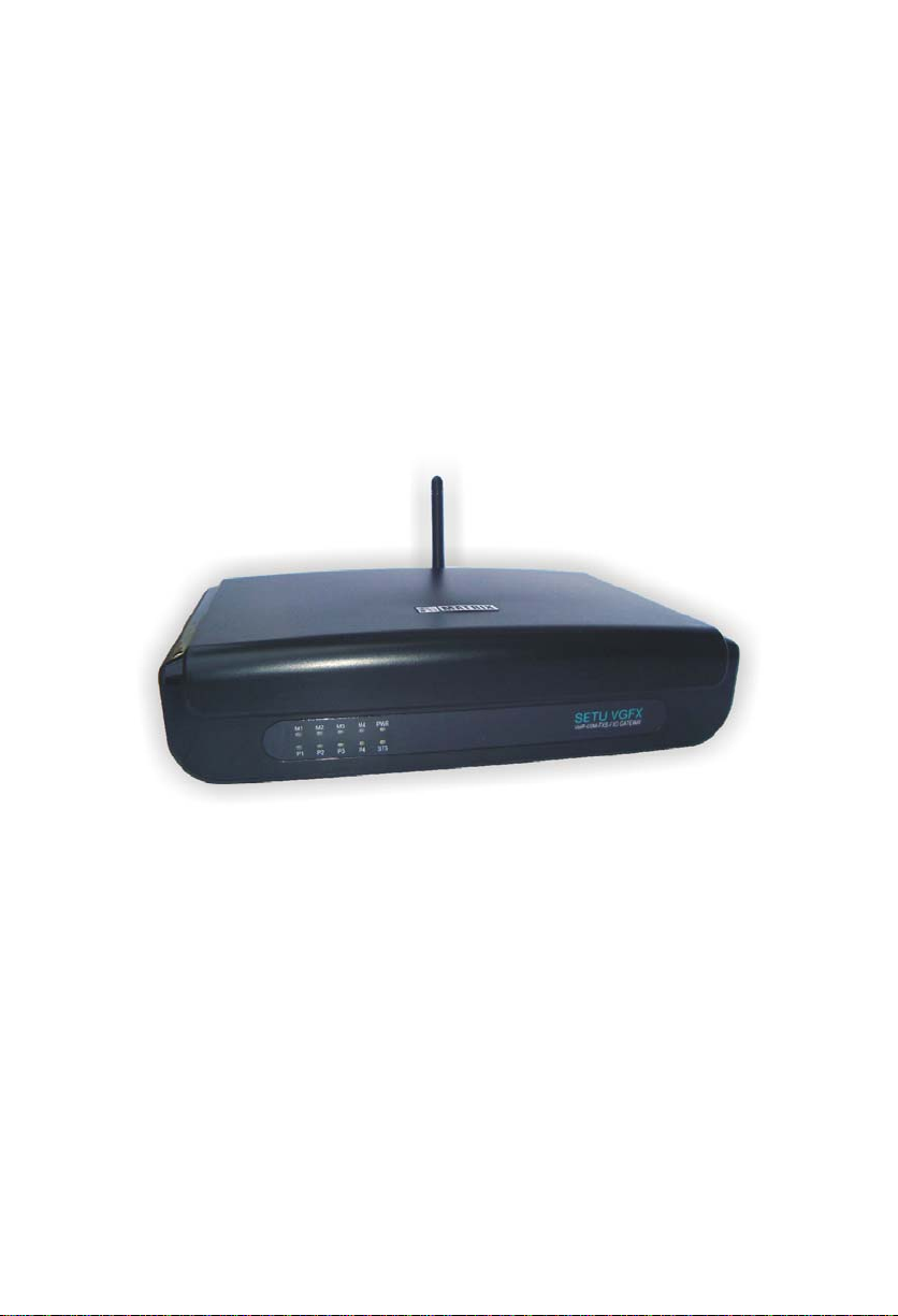
Know your SETU VGFX
SETU VGFX has 1 WAN Port, 2 FXO Ports, 2 FXS Port s, 4 Mobile Port s, 9 SIP
Trunks, Antenna Connecter, a Power Socket and 10 LEDs.
SETU VGFX is available in three different configurations:
1. SETU VGFX8422: supports 4 Mobile Ports, 2 FXO Ports and 2 FXS Ports.
This is the default configuration of SETU VGFX.
2. SETU VGFX8404: supports 4 Mobile Ports and 4 FXS Ports.
3. SETU VGFX8440: supports 4 Mobile Ports and 4 FXO Ports.
This Quick Start is written with reference to the default configuration. The term
SETU VGFX refers to SETU VGFX8422, unless otherwise specified.
LEDs:
There are total 10 LEDs in VGFX. These LEDs are labeled as M1, M2, M3, M4,
P1, P2, P3, P4, STS and PWR as shown in the figure below. These LEDs indicate
the status of ports, various events occurring on the ports and also the error
conditions.
Page 5
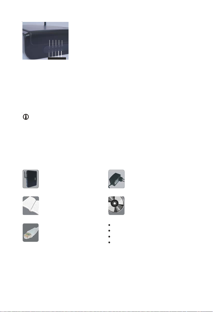
M1 M2 M3 M4 Power
P1 P2 P3 P4 Status
All LEDs are of dual colour (Red/Green) except Power LED which is of single
colour (Red). Power (PWR) and Status (STS) LEDs are non-programmable
whereas all port LEDs are programmable.
By default, LEDs labeled as M1, M2, M3 and M4 show status of Mobile
Ports. LEDs labeled as P1 and P2 show status of FXO Ports and P3 and P4
show status of FXS Ports.
Port LEDs can be programmed for showing the status of SIP Trunks also.
You can program LEDs for showing status of maximum 8 SIP Trunks
simultaneously. (Refer "Step 10" for more details)
Before Y ou Start
Verify Package Contents
SETU VGFX with Antenna
(Rubber ducky SMA)
Quick Start and User Card
Ethernet Cable (RJ45)
Adaptor 12VDC, 2A
(Country Specific)
CD containing System Manual,
Quick Start and User Card
Two Screws M 7/30 with Grips
External Antenna SMA with cable
A Mounting Template
A Warranty Card Set
Make sure that all the above mentioned components are present when you open
the Sales Kit of SETU VGFX. In case any of the part is missing or damaged,
contact the source from where you have purchased your VGFX.
Page 6

Get your Internet Connection ready:
To install VGFX, you must have:
1. Broadband Internet connection from an ISP to make and receive calls through
public internet. If you want to make calls within your network, you do not
need an internet connection.
2. Connection from an Internet Telephony Service Provider (ITSP) to activate
your SIP Trunks. You do not need an ITSP connection for making Peer to
Peer calls.
Get your Network Information ready:
Ask your LAN Administrator/ISP for:
1. IP Address
2. Subnet Mask
3. Gateway Address
4. DNS Address
5. DNS Domain Name
Ask your ITSP for:
1. SIP ID/User ID
2. Authentication User ID (in most cases it is same as SIP ID)
3. Authentication Password
4. Registrar Server Address
5. Registrar Server Port
6. Outbound Proxy Server Address
7. Outbound Proxy Server Port
To install VGFX, you should also have:
1. An active SIM card/s from GSM service provider.
2. Analog trunk line from Public Switched Telephone Network (PSTN).
Installing SETU VGFX
Take proper precautions while installing VGFX to reduce the risk of fire, electric
shock and injury to the system as well as the person using it. (Refer Installation
Precautions and Safety Instructions under 'Protecting SETU VGFX' topic in the
System Manual)
Mounting SETU VGFX on wall:
SETU VGFX should be installed at the airy, dust free and moisture free place.
• Select a suitable place on the wall for mounting SETU VGFX.
• Put the mounting template on the wall and mark the nail hole on the wall.
• Drill a hole of appropriate size.
• Insert the screw and tighten it leaving the screw head a few millimeters
protruded of the wall.
• Check the strength of the nail.
• Hang VGFX on the wall.
Page 7
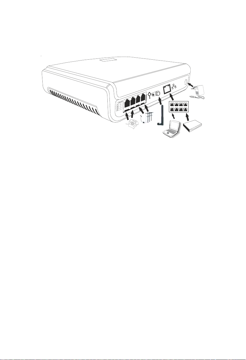
Connecting SETU VGFX
Connect SETU VGFX as shown below:
Ethernet
Adaptor
Switch
PC
Router
RJ11
RJ11
Antenna
• Place SETU VGFX at a suitable place where it can be provided with proper
power supply.
• Connect Ethernet (WAN) Port of SETU VGFX to the LAN Switch/Network of
the Enterprise.
• Connect PSTN line to the FXO Port of SETU VGFX or connect FXO Ports of
SETU VGFX to the FXS Ports of the PBX.
• Connect telephone instruments to the FXS Ports of SETU VGFX or connect
FXS Ports of SETU VGFX to the FXO Ports of the PBX.
• Connect Antenna to SETU VGFX.
• Insert SIM Card into the Mobile Port of SETU VGFX for the mobile network.
If SIM protection is enabled in the SIM Card, ensure that SIM PIN of the SIM
Card and VGFX is same. By default, SIM PIN of all the Mobile Ports of the
VGFX is 1234. To change SIM PIN of the SIM Card, SE is recommended to
take following steps:
• Switch Off VGFX.
• Remove SIM Card and insert the same in the mobile instrument.
• Enable 'SIM PIN at Power ON' parameter in the SIM Card. (This step is
not required if SIM protection is already ON)
• Change the SIM PIN of the SIM Card to 1234 i.e. the default SIM PIN of
VGFX.
• Remove SIM Card from the mobile instrument and insert it in VGFX.
• Change the SIM PIN after VGFX attains normal working position.
• Connect Power Socket of SETU VGFX to the power supply using 12V DC,
2A power adaptor.
Page 8
Switching ON SETU VGFX
After connecting SETU VGFX as shown above, switch ON the power supply.
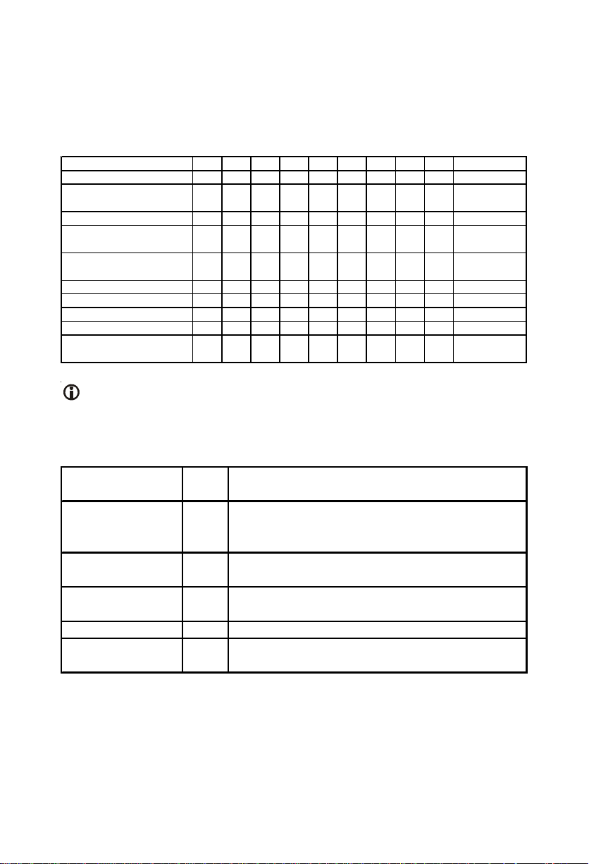
At Power ON, Power LED will turn ON (Continuous Red). Initialization process
will start and LED sequence of all other LEDs during initialization process is
shown in the table given below:
System Status STS P1 P2 P3 P4 M1 M2 M3 M4 Time in MS
Power ON - UBOOT OFF
Kernel UP & LE D Driver
Loaded
Applic at ion Load OFF
VOPP Program
Download Succ es s
All Init Done, S y s t em
goes Live
OFF
OFF
ON ON ON ON ON ON ON ON ON
ON ON ON ON ON ON ON ON ON
OFF OFF OFF OFF OFF OFF OFF OFF OFF 1000 m s
ON
OFF OFF OFF OFF OFF OFF OFF OFF OFF 1000 m s
OFF OFF OFF OFF OFF OFF OFF
ON
ON ON
ON ON ON
ON ON ON ON
OFFOFFOFFOFFOFFOFFOFFOFF 1000 m s
OFFOFFOFFOFFOFFOFF
OFF OFF OFF OFF OFF 200ms
OFF OFF OFF OFF 200ms
1000 ms
1000 ms
(Continuous
Last 2 s t eps )
Red color text (Bold) indicates that led will glow red and Green color text
(Bold+Italic) indicates that led will glow green.
Mobile Port LEDs (M1, M2, M3 and M4) will display following error/event/status
during initialization:
Event/State/
Status
Color Cadence (in ms) (1 cadence is of 4000ms)
500ms On- 500ms Off – 500ms On-500ms Off-
GSM Initialization Red
500msOn-500ms Off- 500ms On- 500ms Off (4
Blinks)
PUK required Red
SIM PIN faulty Red
500ms On- 500ms Off – 500ms On-500ms Off500msOn-1500ms Off (3 Blinks)
500ms On- 500ms Off – 500ms On-2500ms Off (2
Blinks)
SIM Absent Red 500ms On- 3500ms Off (1 Blinks)
GSM network
absent
Red 1sec On – 1sec Off
Page 9
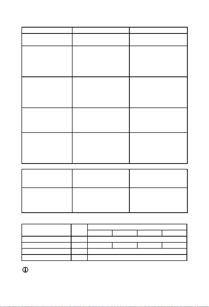
System LED (STS) will display the following error/events/status:
System Status LED Status Comment
VoPP Program Down
Load Fail.
Gateway started
successfully and
NW_Up_SIP_Up_CDR
_OK
Red On Continuously VoPP Program download
fail
GREEN Blink
1sec On-1sec Off
Gateway Started
Successfully.
Network link is Up. SIP
stack is Up CDR buffer is
not full
NW_Down_SIP_
down_CDR_OK
Green Blink
500 ms on-500ms off-500
ms on-500ms off-500 ms
Network link is down. SIP
stack is down CDR buffer
is not full
on-500ms off- 500 ms on500ms off
NW_Up_SIP_down_C
DR_OK
Green Blink
500 ms on-500ms off-500
ms on-500ms off- 500 ms
Network link is Up.
SIP stack is down CDR
buffer is not full
on-1500ms off
NW_Down_SIP_
down_CDR_Full
Red Blink
500 ms on-500ms off-500
ms on-500ms off-500 ms
Network link is down. SIP
stack is down CDR buffer
is full
on-500ms off- 500 ms on500ms off
NW_Up_SIP_down_C
DR_Full
Red Blink
1sec On-1sec Off
Network link is up.
SIP stack is up CDR
buffer is full
NW_Up_SIP_Up_CDR
_Full
Red Blink
500 ms on-500ms off-500
ms on-500ms off- 500 ms
Network link is up.
SIP stack is up CDR
buffer is full
on-1500ms off
FXS/FXO/Mobile Port LED status during normal functioning is as shown below:
Event/State/Status Color Cadence (1 cadence is of 4000ms)
ON OFF ON OFF
Port Idle/Disable Incoming Ring Event Red 400 200 400 3000
Off-Hook Event Red
Speech Green
OFF
Continuous
Continuous
LED of FXS Port, that is used to enter the programming mode, will glow
continuous GREEN while the system is in programming mode. Once the
command to exit programming mode is issued, the LED will turn continuous
Page 10
RED i.e. will display the Off-Hook Event.
You can also program Port LEDs for showing the status of SIP Trunks. For
example, if you are using only two mobile ports and other two mobile ports are
disabled then you can program these LEDs for showing the status of SIP T runks.
(Refer Step 13: 'Checking the Status' for more details)
If LED is programmed for SIP Trunk, it will display following error/event/status:
Event/State/Status Color
SIP Disable SIP Registered Green
SIP Registration
Failed
SIP Authentication
Failed
Red
Red 200 200 200 3400
Cadence (1 cadence is of 5000msec)
ON OFF ON OFF
OFF
Continuous
Continuous
When all LEDs are programmed for SIP T runks then no LED indication would
be displayed for FXS/FXO and Mobile Port.
Accessing Web Jeeves:
Programming of SETU VGFX can be done using Web JEEVES only . It does not
support programming of VGFX using telephone instrument except few Network
Port Parameters. To access Web JEEVES, Network Port Parameters should be
programmed first using conventional phone. Follow the steps shown below:
Accessing web jeeves is a very important step in programming VGFX. To access
web jeeves, Network Port Parameters should be programmed first using
conventional phone.
1. Pick up handset of analog phone connected to SETU VGFX.
2. Dial the programming access code #19 followed by default password 1234.
You will get programming tone.
3. To access Web JEEVES using computer/computers in LAN to which VGFX
is connected, change IP address and Subnet Mask of SETU VGFX to bring
VGFX and computer/computers in LAN in the same subnet. Ensure that
their IP Addresses are different.
4. To program Network Port IP address, use command: 1 1-IP Address-#*
Where,
IP address is of 12 digits in XXX.XXX.XXX.XXX format. Each octet is of
three digits ranging from 001 to 255. For example, to program IP address
192.168.1.120, enter the command 1 1-192168001120-#*. By default, IP
Address of VGFX is 192.168.001.176.
Page 11

5. To program Network port Subnet Mask, use command: 12-Subnet Mask-#*
Where,
Subnet Mask is of 12 digits in XXX.XXX.XXX.XXX format. Each octet is of
three digits. V alid range is 0, 128, 192, 224, 240, 248, 252, 254 and 255. For
example, to program Subnet Mask 255.255.254.0, enter the command
12-255255254000-#*. By default, Subnet Mask of VGFX is
255.255.255.000.
6. To exit programming mode, use command: 00#*.
VGFX restarts as soon as IP Address or Subnet Mask is changed.
7. After changing IP Address and Subnet Mask as shown above, open web
browser of the computer connected to VGFX and enter IP Address of VGFX
in the URL of the web browser. Login page of VGFX Web JEEVES will
appear on the screen.
8. Enter default password 1234 in the login page and reach the home page.
Program all the necessary parameters of SETU VGFX one by one by clicking
the links given on the left side of the web page.
Programming SETU VGFX
Once VGFX is switched ON, the SE is advised to program it in the following
sequence:
1. SIM PIN
2. Date and Time Settings
3. Call Progress Tones
4. Ring Type
5. Mobile Network Selection
6. SIP Trunk Parameters
7. Routing Groups
8. Routing Mechanism
9. Network Port Parameters
After programming VGFX in above mentioned sequence, you will be able to
make and receive calls.
• Open Web browser of the computer connected to VGFX.
• Enter IP Address of SETU VGFX in the URL field and press 'Enter' key.
Login Page of SETU VGFX will appear on the screen.
Page 12

• Enter default SE password (1234) in the 'Password' field and click on 'Login'
button. Home page of Web JEEVES will open up.
Page 13

Step 1: SIM PIN
SIM PIN is a security feature used by the GSM network. This feature is used to
protect the SIM card inserted in the system from mis-use.
• If this feature is enabled, the network will ask the user to enter SIM PIN at
every Power On.
• If the user enters wrong SIM PIN for three times then the network suspects
the user and asks for the Personal Unlock Keyword (PUK).
• If wrong PUK number is entered for ten times then the SIM Card will become
useless.
Follow the steps given below to enable SIM protection or change SIM PIN in
VGFX:
• Switch Off VGFX.
• Remove SIM card and insert the same in the mobile instrument.
• Enable 'SIM PIN at Power ON' parameter in the SIM card. (This step is not
required if SIM protection is already ON)
• Change the SIM PIN of the SIM card to 1234. (default)
• Remove SIM card from the mobile instrument and insert it in VGFX.
• Switch on the system and change the SIM PIN after it attains normal working
position.
SE should take above steps to change the SIM PIN of the SIM Card in case
SIM protection of SIM Card is enabled and SIM PIN of SIM Card and VGFX
is different else VGFX will not initialize.
(Refer 'Port Parameters-Mobile' feature in System Manual for more details)
Step 2: Date and Time
Click on 'Date and Time Settings' link and program following parameters:
Page 14

• Current Date: Enter current date in DD-MM-YYYY format.
Valid range for date = 01 to 31
Valid range for month = January to December
Valid range for year = 2008 to 2099
• Current Time: Enter current time in HH-MM-SS format.
Valid range for hour = 00 to 23
Valid range for minutes = 00 to 59
Valid range for seconds = 00 to 59
• Current Day: Depending on the current date entered by SE, System
automatically sets current day in this field.
• NTP Address: In this field, select one of following Time Servers:
1. Ntp1.cs.wisc.edu
2. Time.windows.com
3. Time.nist.gov
Default = Ntp1.cs.wisc.edu
OR
Enter IP address of NTP server address manually.
• Maximum Length = 40 characters
• All ASCII characters allowed
Page 15

• Time Zone: Select the time zone from the given combo box depending on
the country of installation of SETU VGFX.
After programming Date and Time settings, click on submit button at the
bottom of the page to save the settings.
Step 3: Call Progress Tones
Click on 'Call Progress Tones' link and program following parameters:
• Select either Countrywise or Customized option. By default, Countrywise
option is selected.
• If 'Countrywise option' is selected then the combo box for selecting the country
becomes editable. Select the country in which SETU VGFX is installed. By
default, INDIA is selected.
• If 'Customized option' is selected then countrywise combo box becomes
uneditable and CPTG table will become editable. Program frequency and
cadence for each tone. By default, values for all tones are displayed as per
the last country selected.
• Frequency1: Program frequency1 for each tone. Range of frequency 1
is 300-1400 Hz for all tones.
Page 16

• Frequency2: Program frequency2 for each tone. Range of frequency 2
is 20-1400 Hz for all tones.
• Operator parameter has three options:
1. No: If 'No' is programmed then Frequency 2 is not applicable.
2. * (Modulation): If '*' (Modulation) is programmed then Frequency 1
and Frequency 2 is used as modulation i.e. F1* F2.
3. + (Addition): If Addition (+) is programmed then Frequency 1 and
Frequency 2 is used as addition i.e. F1 + F2.
• Cadence: Program Cadence ON time and OFF time.
1. ON time (msec): Range of Cadence ON Time is from 0000 to 9999
msec for all tones.
2. OFF time (msec): Range of Cadence OFF Time is from 0000 to
9999 msec for all tones.
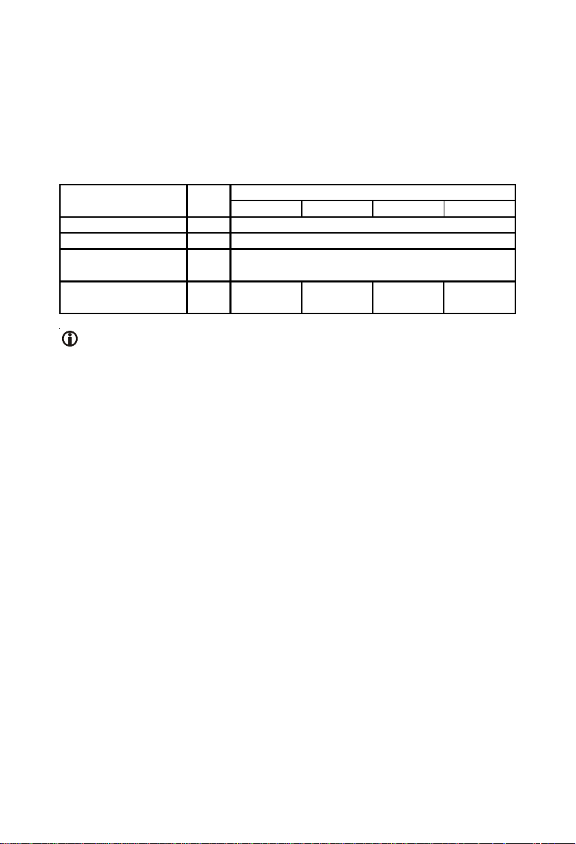
Default Cadence for all the tones for INDIA is shown below:
Tone Type
Dial Tone 400 * 25999900000
Ring Back Tone 400 * 25 400 200 400 2000 0 0
Error Tone 1 400No 02502500000
Error Tone 2 400No 0100010000000
Busy Tone 400No 07507500000
Confirmation Tone400No 01001000000
Feature Tone/
Programming Tone
Prompt Tone 400 No 0 100 100 100 2000 0 0
Routing Tone 400No 010019000000
Intrusion Tone 400 No 0 200 100 200 7500 0 0
Freq. 1
Operator
(Hz)
400No 01009000000
Freq. 2
(Hz)
ON
Time1
OFF
Time1
Cadence (msec)
ON
Time2
OFF
Time2
ON
Time3
OFF
Time3
Call Progress Tones and the country selected will not be defaulted when
you default the VGFX.
(Refer 'Call Progress Tones' feature in System Manual for details)
Step4: Ring Type
Click on 'Ring Type' link and program the following parameters:
Page 17

• In 'Ring Type' field, select the country in which SETU VGFX is installed.
• Ring cadence value will change in Ring Cadence table automatically as per
the country programmed in Ring Type field. Ring Cadence t able is un-editable.
(Refer 'Ring Type' feature in System Manual for details)
Step5: Mobile Network Selection
Click on 'Mobile Network Selection' link and program the following parameters:
• Network Selection Mode: Select one of the following two network selection
modes:
1 Automatic
2 Manual
Default = Automatic
Page 18

• Network Operator Code: If mode programmed for network selection is
'Manual' then program network operator code and set the priority for network
operators with which the SIM can get registered.
Maximum Length = 8 digits
Default = Blank.
In Manual mode for network selection, SIM Card will be registered only with
the network that is supported by the network operator of the SIM Card used
in the system.
(Refer ‘Mobile Network Selection’ in System Manual for more details).
Step6: SIP Trunk Parameters
Click on 'SIP Trunk Parameters 1' link and program the following parameters.
Page 19

• Port Enable?: Enable the status of the SIP T runk. Y ou will be able to receive
incoming calls and make outgoing calls only if the SIP Trunk is enabled.
• Valid options: Yes/No
Default = No
• SIP ID: Enter the SIP ID provided by the ITSP in this field.
• Maximum Length = 40 characters
• All ASCII characters allowed
Default = *
In case of Peer to Peer calls, the first SIP Trunk with SIP ID programmed as
'*' will always be used for routing the incoming call.
Page 20

• Registrar Servers' Address: Enter SIP registrar server address provided
by ITSP in this field. It can be an IP address or domain.
• Maximum Length = 40 characters
• All ASCII characters allowed
Default = Blank
• Registrar Servers' Port: Enter registrar server listening port provided by
ITSP in this field.
• Valid range = 1024 to 65535
Default = 5060
• Authentication User ID: Enter User Id provided by ITSP for registering the
SIP Trunk with the SIP server.
• Maximum Length = 40 characters
• All ASCII characters allowed
Default = Blank
• Authentication Password: Enter the authentication password provided by
ITSP.
• Maximum Length = 24 characters
Default = Blank
• Outbound Proxy Server: Enable outbound proxy , if your ITSP have a SIP
outbound server to handle voice calls.
• Valid options: Yes/No
Default = No
• Outbound Proxy Server's Address: Enter the outbound proxy server
address provided by ITSP if outbound proxy is enabled. It can be IP address
or domain.
• Maximum Length = 40 character
• All ASCII characters allowed
Default = Blank
• Outbound Proxy Server's Port: Enter the outbound proxy server's listening
port provided by ITSP.
• Valid range = 1024 to 65535
Default = 5060
• Source Port IP Address: Select one of the following options as Source
Port IP Address.
1. Use Network Port IP Address
2. Use IP Address fetched using STUN
3. Use Router's Public IP Address
By default, Source Port IP Address is 'Use Network Port IP Address'.
Page 21

• Use Symmetric RTP?: This parameter is applicable only for peer to peer
calls. Select 'Yes' if SETU VGFX is located on public IP and calls are made
and received from the SIP client located behind the NAT router.
• Valid options: Yes/No
Default = No
(Refer ‘Port Parameter-SIP’ in System Manual for more details).
Step7: Routing Groups
Create Routing Groups for all the port types. To program Routing Groups for
Mobile Ports, click on 'Mobile Port Groups' link and program the following
parameters:
• Member Selection Method: In this field, select the method for selecting
member from a group for placing the call on Mobile Port.
• Valid options: First Free/Rotation
Default = Rotation
• Members: Program desired Mobile Port number in each of the member
field. VGFX shall place the call on any of these members as per member
selection method programmed for the group.
Similarly create Routing Groups for FXS Ports, FXO Ports and SIP Trunks
also.
(Refer 'Routing Group' feature in System Manual for more details)
Page 22

Step8: Destination Number Determination Method:
Routing mechanism in VGFX involves two things: Destination Number
Determination Method and Destination Port Determination Method. VGFX
supports following method for Destination Number Determination Method:
1. Number Not Required
In this method, destination number would be blank. Call will not be answered
till the destination port is answered. This method is applicable for FXO Ports,
Mobile Ports and SIP Trunks. Generally this option is used when incoming
call is to be routed on FXS Port.
2. Fixed Destination Number
In this method, call is routed to a fix destination number programmed. To
use this method, program destination number in 'Fixed Destination Number'
field of the respective port. Call will not be answered till the destination port
is answered. This method is applicable for FXO Ports, Mobile Ports and SIP
Trunks.
3. Based on Calling Number
In this method, call is routed to a specific number depending upon the calling
party's number. To use this method, 'Destination Number Determination:
Calling Number Based' table should be programmed. Call will not be
answered till the destination port is answered. This method is applicable for
FXO Ports, Mobile Ports and SIP Trunks.
4. Based on Called Number
In this method, call is routed to a number received on the SIP Trunk. Call will
not be answered till the destination port is answered. This method is
applicable for SIP Trunks only.
5. Manual Dial
In this method, incoming call will be answered and VGFX will feed dial tone
to the caller. Call is routed to the number dialed manually by the caller. This
method is applicable for all port types.
For SIP Trunks, only four calls can be answered simultaneously.
Page 23

Programming Destination Number Determination Method:
• Click on 'Mobile Port Parameters2' link and select Destination Number
Determination Method.
Similarly , open 'FXS Port Parameters 2', 'FXO Port Parameters 2' and 'SIP
Trunk Parameters 2' and select Destination Number Determination Method
for FXS Ports, FXO Ports and SIP Trunks respectively.
Step9: Destination Port Determination Method:
Routing mechanism in VGFX involves two things: Destination Number
Determination Method and Destination Port Determination Method. VGFX
supports following method for Destination Port Determination Method:
1. Fixed
In this method, call is routed using 'Routing Groups' programmed for the
respective port. This method is applicable for all port types.
2. Destination Number Based
In this method, calls originated on the source port are routed through a port
group based on the destination number dialed by the caller. To use this
method, program 'Port Routing: Destination Number Based' table. This
method is applicable for all port types.
3. Calling Number Based
In this method, calls received on the source port are routed through a port
group based on the calling party's number. To use this method, program
'Port Routing: Calling Number Based' table. This method is applicable for
FXO Ports, Mobile Ports and SIP Trunks.
Page 24

Programming Destination Port Determination Method:
• Click on 'Mobile Port Parameters2' link and select Destination Port
Determination Method.
Similarly , open 'FXS Port Parameters 2', 'FXO Port Parameters 2' and 'SIP
Trunk Parameters 2' and program Destination Port Determination Method
for FXS Ports, FXO Ports and SIP Trunks respectively.
Step10: Network Port Parameters
Click on 'Network Port Parameters' and program following parameters:
Page 25

• Connection T ype: Select the type of connection provided by service provider
in this field.
• Valid options: Static/DHCP/PPPoE
Default = Static
When DHCP is selected as the connection type then PPPoE parameters, IP
parameters and DNS Settings parameters would become uneditable.
• PPPoE Parameters: Program following parameters when connection type
selected is PPPoE.
User ID: Enter PPPoE user id given by service provider manually in this
field.
• Maximum Length: 16 characters
• All ASCII characters allowed
Default = Blank
Password: Enter password of PPPoE user id provided by service provider
manually in this field.
• Maximum Length = 16 characters
• All ASCII characters allowed
Default = Blank
Page 26

• Static IP Parameters: Program IP address, Subnet Mask and Gateway
Address manually in the following fields if connection type selected is Static.
IP Address: Enter IP Address in this field.
• Maximum Length = 15 characters
• Valid Range = 000 to 255 for first three octets and 000 to 254 for last
octet
Default = 192.168.001.176
Subnet Mask: Enter Subnet Mask Address in this field.
• Maximum Length = 15 characters
• V alid range of octets = 000, 128, 192, 224, 240, 248, 252, 254 and 255
Default = 255.255.255.000
Gateway: Enter Gateway Address in this field.
• Maximum Length = 15 characters
• Valid range of octets = 000 to 255
Default = Blank.
• DNS Setting: Select either Static DNS or Automatic DNS. By default, S tatic
DNS is selected.
Automatic DNS: If Automatic DNS is selected then DNS Address and DNS
Domain Name shall be assigned automatically by the server.
Static DNS: If S tatic DNS is selected then program the following parameters
manually:
• DNS Address: Program DNS address provided by the service provided
manually in this field.
1. Maximum Length = 15 characters
2. Valid range of octets = 000 to 255.
• DNS Domain Name: Program DNS Domain Name in this field.
1. Maximum Length = 40 characters
2. All ASCII characters allowed
• Router's Public IP Address: Program public IP address of the router in this
field if 'Source Port IP Address' is set to 'Use Router's Public IP Address' in
SIP parameters.
• Maximum Length = 15 characters
• Valid range = 000 to 255
Default = Blank.
(Refer 'Port Parameters-SIP' in system manual for more details)
Page 27

• STUN: Program STUN parameters if SETU VGFX is located behind the
NA T router.
Server Address: Enter STUN server address in this field.
• Maximum Length = 40 characters
• All ASCII characters allowed
Default = Blank
Server Port: Enter STUN Server's listening port in this field.
• Valid range = From 1024 to 65535
Default = 3478
Use SIP Port fetched using STUN? This parameter is applicable only when
'Source Port IP Address' is set to 'Use IP Address fetched using STUN'.
• Valid options = Yes/No
Default = No
• Listening Port
SIP Listening Port: SIP Listening port defines the port on which SETU
VGFX listens for SIP messages.
• Valid range = From 1024 to 65535
Default = 5060
RTP Listening Port: R TP Listening port defines the port on which SETU
VGFX listens for RTP packets.
• Valid range = From 1024 to 65526
Default = 8000
SETU VGFX will reboot as soon as you submit the page after changing any
of the Network Port parameters and you will logout of the Web JEEVES.
• If SETU VGFX is connected directly to the Computer for configuring the
system then remove the Ethernet Cable from the Computer and connect it
to the Broadband Modem switch.
• To know IP Address of your SETU VGFX, follow the steps given below:
• Enter programming mode by dialing #19-1234 (Default SE Password)
through FXS Port.
• Dial 21-#* and go On-Hook during confirmation tone.
• VGFX will display its IP Address as CLI on FXS Port.
• Note down the IP Address and exit programming mode.
• Access Web JEEVES using the displayed IP Address through one of
the Computers connected to the LAN Switch or through Internet ready
access Computer (if IP Address of VGFX is Public IP).
Page 28

Step 11: Reinstate the Default Settings
SETU VGFX enables the user to default VGFX and assign default values to all
programmable parameters by using 'System Default' feature. This feature will
set all parameters to factory set values except the following features:
1. Call Detail Records
2. Date and Time
3. Call Progress Tones
4. Ring Type
5. SIM PIN (in Mobile Port Parameters)
Click on 'Default SETU VGFX' link. An alert message window will appear stating:
• This option shall assign default values to all the programmable parameters
of the SETU VGFX and will restart. Do you want to continue?" OK/Cancel.
Click on 'OK' button. All the programmable parameters shall be defaulted
except those mentioned above, followed by system restart.
Step12: Restore SE Password
T o program VGFX, you must login in the Jeeves or enter programming command
using SE password. However, if you forget SE Password it is possible to reset
the same by changing the jumper position.
To default SE password, follow the steps given below:
• Switch Off VGFX.
• Locate a mini jumper J8 on the card. In normal condition, it is in BC position.
BC Position
J8
AB Position
• Change the jumper position from BC to AB.
• Switch On the system and wait till it gets initialize.
• Switch Off VGFX and restore the jumper in its original position.
• Switch On the system again.
• SE password gets default to 1234.
Page 29

Step13: Checking the Status
SIP T runk Status:
You can check SIP Trunk Status in two ways:
1. Through LED Indication
2. Through Web JEEVES
Through LED Indication:
Port LEDs can be programmed for showing the status of SIP Trunks also.
You can program LEDs for showing status of maximum 8 SIP Trunks
simultaneously . Programming of LEDs is done using Web JEEVES as shown
below:
• Open Web JEEVES of SETU VGFX. (Refer 'Accessing Web JEEVES'
topic)
• Click on 'System Port LED' link.
• Program LEDs as per your requirement. Once the LEDs are programmed
for showing status of the SIP Trunks, it will display the status of SIP
Trunks.
If LED is programmed for SIP Trunk, it will display following error/event/
status:
Event/State/Status Color
SIP Disable SIP Registered Green
SIP Registration
Failed
SIP Authentication
Failed
Red
Red 200 200 200 3400
Cadence (1 cadence is of 5000msec)
ON OFF ON OFF
OFF
Continuous
Continuous
When all LEDs are programmed for showing status of SIP Trunks then
status of FXS, FXO and Mobile Port will not be displayed.
Page 30

Through Web JEEVES:
Open Web JEEVES of SETU VGFX and click on the 'SIP Trunk Status' link
to check status of SIP Trunks. Following page will be displayed:
Following is a brief description of the parameters displayed on the 'SIP T runk
Status' page.
1. SIP Trunk Number: This field displays the SIP Trunk number.
2. Status: This field displays the st atus of SIP T runk. Different status option
which can appear in this field is explained below:
Status Description
Disable Shows that SIP Trunk is disable
Registering Shows that SIP Trunk is enable and waiting for
response from the SIP server
Registered Shows that SIP Trunk is registered with the SIP
server.
Failed Shows that some error has occurred in the SIP
Trunk and no calls can be made using it
(applicable only in case of Proxy Account).
Peer to Peer Shows that SIP Trunk is configured for Peer to
Peer calling
3. Registration Time: This field displays the time left to re-register the
SIP Trunk after it gets registered successfully. This time is provided by
Page 31

the registrar server. When the registration period get s over, SIP T runk is
to be registered again.
4. Registration Retry Count: This field displays the total number of register
message which is sent to the registrar server for registering SIP Trunk.
5. Failed Reason: This field displays the reason for registration failure, if
registration of SIP T runk fails with the registrar server. Registration failure
occurs because of various reasons such as: Message send fail, Failed
to create register client, Failed to send request, Error response-4xx to
6xx etc.
Network Status:
Y ou can check Network Status through Web JEEVES only. Open Web JEEVES
of SETU VGFX and click on the 'Network Status' link. Following page will be
displayed:
Brief description of the parameters displayed on the 'Network St atus' p age is as
follows:
1. IP Address: This field displays IP address currently assigned to VGFX.
2. Subnet Mask: This field displays Subnet Mask currently assigned to VGFX.
3. Gateway Address: This field displays Gateway Address assigned to VGFX.
Page 32

4. MAC Address: This field displays MAC Address assigned to VGFX.
5. DNS Address: This field displays the DNS address of VGFX.
6. NAT Type: This field displays NAT Type, if STUN is enabled in VGFX. The
NA T Types Supported by VGFX are:
• Unknown
• Open
• Conenat
• Restrictednat
• Portrestrictednat
• Symmetricnat
• Symmetricfirewall
• Blocked
7. Router's Public IP Address: This field displays Router's Public IP address
programmed in the Network Port Parameters.
8. IP Address fetched using STUN: This field displays the IP address fetched
using STUN if STUN server address is programmed.
9. SIP Port fetched using STUN: This field displays the SIP port fetched using
STUN if STUN server address is programmed.
10. Stack Status: In this field, strings such as Idle, DHCP Response wait, PPPoE
response wait, NA T checking response wait, construct and error is displayed.
Test Call
Now you can make and receive calls either from a cell phone or from analog
phone connected to VGFX follow the steps given below to make a test call:
Making a Call
• Pick up the handset of telephone instrument connected to SETU VGFX.
You will get dial tone.
• Dial the desired number.
• Talk after the called party replies the call.
• Dial 'Call Disconnect' access code or replace the handset to disconnect the
call.
Receiving a Call
• Ring on telephone instrument connected to SETU VGFX.
• Lift the handset to talk.
• You will be in speech with the calling party.
• Replace the handset to disconnect the call.
Page 33

Appendices
Features at Glance
Feature Description Feature Code
To Enter Programming Mode
To Exit Programming Mode
To Set Hotline
To Cancel Hotline
To Enable Call Waiting
To Disable Call Waiting
To Set DND
To Cancel DND
To Set Call Forward Unconditional
To Cancel Call Forward Unconditional
To Set Call Forward Busy
To Cancel Call Forward Busy
To Set Call Forward No Reply
To Cancel Call Forward No Reply
To Program Hotline Number
To Program Hotline Timer
To Program Call Forward Unconditional
Number
To Program Call Forward Busy Number
To Program Call Forward No Reply Number
To Program No-Reply Timer
For Call Hold
To Retrieve Held Call
For Call Toggle (Call Split)
To Reject the Waiting Call and Speech with
Current Call
To Ignore the Waiting Call and Speech with
Current Call
To Accept the Waiting Call and Hol d Curre nt
Call
To Accept the Waiting Call and Rel e ase
Current Call
For Blind Transfer
For Conference
For Using Supplementary Se rvi ces of
Service Provider
For Attended Transfer
For Making a New Call
To Disconnect Call
#19-User Password (Default Password =
1234)
00#*
#151-1
#151-0
#16-1
#16-0
#18-1
#18-0
#131-1
#131-0
#132-1
#132-0
#133-1
#133-0
#152-Destination Number-End-of-
@
Dialing
#153-X (X is the timer value)
#135-Destination number-End-of-
@
Dialing
#136-Destination Number-End-of-
@
Dialing
#137-Destination Number-End-of-
@
Dialing
#139-XX (XX is time in seconds)
Flash
Flash
#2
#31
#32
#33
#34
#6
#8
#4
^ (On-Hook)
#91
#92
Page 34

@ Dial # as end of dialing if end of dialing digit is programmed or wait till
expiry of inter digit wait timer.
System Commands
Description System Commands
To Program Network IP Address
To Program Network Subnet Mask
To Program the Connection Type
To Enable/Disable VLAN tag
To Display the Connection Type
To Display the Network IP Address
To Display the Network Subnet Mask
To Display the Network Gateway Address
To Display the DNS Address
To Display the Signal Strength of the GSM Network
To Display the Status of SIP Accounts
11-IP Address-#*
12-Subnet Mask-#*
10-Code-#*
31-Code-#*
20-#*-Go On-Hook
21-#*-Go On-Hook
22-#*-Go On-Hook
23-#*-Go On-Hook
24-#*-Go On-Hook
26-Mobile Port-#*
27-SIP Accounts-#*
Page 35

Page 36

MATRIX TELECOM PVT. LTD.MATRIX TELECOM PVT. LTD.
MATRIX TELECOM PVT. LTD.
MATRIX TELECOM PVT. LTD.MATRIX TELECOM PVT. LTD.
Corporate Office:
394-GIDC, Makarpura, Vadodara - 390010, India.
Tel.:+91 265 2630555, Fax: +91 265 2636598
E-mail: Info@MatrixTeleSol.com
Factory:
39-GIDC, Waghodia - 391760, Dist. Vadodara, India.
Tel.: +91 2668 262056/57
Technical Support:
Tel.: +91 2668 263172/73, Fax: +91 2668 262631
E-mail: Support@MatrixTeleSol.com
www.MatrixTeleSol.com
Version 1, August 2009
 Loading...