

Page 1

SETU ATA2S
System Manual
Page 2

Page 3
SETU ATA2S
VoIP-FXS Adaptor
System Manual
Page 4

Documentation Disclaimer
Matrix Comsec reserves the right to change, at any time, without prior notice, the product design, specifications,
components, as engineering and manufacturing may warrant.
This is a general documentation for all models/configurations of the product. The product may not support some of the
features/facilities described in this document.
While every reasonable effort has been made to ensure accuracy of content in this document, Matrix Comsec assumes
no responsibility for errors or omissions that may occur herein. No liability is assumed for damages, costs, expenses
resulting from unauthorized modifications or repairs to the product; failure to use information or to comply with the
installation, operation and maintenance instructions contained in this document.
Copyright
All rights reserved. No part of this document may be copied or reproduced in any form or by any means without the prior
written consent of Matrix Comsec.
Version 6
Release date: July 25, 2011
Page 5

Contents
Introduction..................................................................................................................................................... 1
Welcome! ............................................................................................................................................................ 1
About this System Manual .................................................................................................................................. 1
How to Read this System Manual ....................................................................................................................... 2
Know Your SETU ATA2S ................................................................................................................................ 5
Overview ............................................................................................................................................................. 5
Applications of SETU ATA2S .............................................................................................................................. 7
Getting Started................................................................................................................................................ 9
Preparing for Installation ..................................................................................................................................... 9
Connecting SETU ATA2S ................................................................................................................................. 11
Configuring SETU ATA2S ................................................................................................................................. 13
Basic Settings ............................................................................................................................................... 19
Region ............................................................................................................................................................... 21
SIP Trunks ........................................................................................................................................................ 23
FXS Ports .......................................................................................................................................................... 36
Passwords ......................................................................................................................................................... 43
Network Parameters ......................................................................................................................................... 47
Advanced Settings ....................................................................................................................................... 53
System Parameters ........................................................................................................................................... 53
Dialed Number Table ........................................................................................................................................ 60
Peer-to-Peer Numbers ...................................................................................................................................... 63
Digest Authentication ........................................................................................................................................ 67
Daylight Saving Time ........................................................................................................................................ 70
Static Routing .................................................................................................................................................... 73
Restart SETU ATA2S ........................................................................................................................................ 76
Reinstate Factory Defaults ................................................................................................................................ 77
Software Upgradation ....................................................................................................................................... 79
Syslog (Debug) ................................................................................................................................................. 81
PCAP ................................................................................................................................................................ 84
Auto Configuration ............................................................................................................................................ 87
Features of SETU ATA2S.............................................................................................................................. 91
Call Hold ............................................................................................................................................................ 91
Making A Second Call ....................................................................................................................................... 92
Call Transfer ...................................................................................................................................................... 93
Table of Contents i
Page 6

Call Toggle ........................................................................................................................................................ 95
Call Waiting ....................................................................................................................................................... 96
Conference ........................................................................................................................................................ 99
Do Not Disturb (DND) ..................................................................................................................................... 100
Call Forward .................................................................................................................................................... 102
Hotline ............................................................................................................................................................. 107
Caller ID Restriction ........................................................................................................................................ 110
Selective SIP Trunk Access ............................................................................................................................ 112
Speed Dialing .................................................................................................................................................. 113
Supplementary Services of Service Provider .................................................................................................. 115
Multi-Stage Dialing .......................................................................................................................................... 116
End of Dialing .................................................................................................................................................. 122
System Status ............................................................................................................................................. 123
Viewing System Status from Jeeves ............................................................................................................... 123
Viewing System Status on Phone ................................................................................................................... 128
Appendix ..................................................................................................................................................... 131
Call Progress Tone Generation ...................................................................................................................... 131
Ring Cadences ................................................................................................................................................ 132
Frequently Asked Questions (FAQs) .............................................................................................................. 133
Acronyms ........................................................................................................................................................ 136
Features at a Glance ....................................................................................................................................... 137
Product Specifications ..................................................................................................................................... 138
System Commands ......................................................................................................................................... 141
Warranty Statement ........................................................................................................................................ 143
Regulatory Information .................................................................................................................................... 145
Open Source Licensing Terms and Conditions ............................................................................................... 147
Index ............................................................................................................................................................ 153
ii Table of Contents
Page 7

CHAPTER 1
Introduction
Welcome!
Thank you for choosing SETU ATA2S. This product is designed to give you high performance combined with real
ease of use. We hope you will make optimum use of this intelligent, feature-packed VoIP Phone Adapter. Please
read this document before installing SETU ATA2S.
About this System Manual
This document contains detailed information and instructions for installing, configuring, and operating SETU
ATA2S. It also contains information on maintenance and safety instructions.
Intended Audience
This System Manual is aimed at:
Network Administrator and System Engineers, who will install, maintain and support SETU ATA2S. It is
assumed that they have some experience in installing VoIP Phone Adapters and are familiar with VoIP
technology.
End Users, the persons/organizations who will use SETU ATA2S. They include home users, personnel of
small and medium businesses, large enterprises, other commercial and public organizations/institutions.
Organization of this document
This System Manual contains the following chapters:
Introduction: Gives information about this system manual.
Know Your SETU ATA2S: Provides overview of SETU ATA2S.
Getting Started: Contains information on how to install SETU ATA2S, how to configure the device using the
web-based programming tool, Jeeves, and using the phone connected to the device.
Configuring Basic Settings: Has instructions for configuring the basic parameters of SETU ATA2S, which
are sufficient to get the system into operation.
Matrix SETU ATA2S System Manual 1
Page 8

Configuring Advanced Settings: Contains instructions for configuring the more advanced features and
facilities of SETU ATA2S.
Features of SETU ATA2S: Describes in detail, the features of SETU ATA2S, along with instructions for
configuring and using these features.
System Status: Describes the status indicators for the LAN and WAN ports, SIP trunk registration, and
details of the System Firmware.
How to Read this System Manual
This System Manual is organized in a manner to help you get familiar with SETU ATA2S, learn how to install it, how
to connect it to the IP network, how to configure the Basic Settings that allow you to start making and receiving
calls, and move on to the Advanced configuration to use the special features and functions. You may read it in the
sequence it is organized.
Conventions used in this System Manual
Instructions
The instructions in this document are written in a step-by-step format. Each step, its result, indication/notification,
where and as it occurs, has been described.
Notices
The following symbols have been used for notices to draw your attention to important items.
Important: to indicate something that requires your special attention or to remind you of something you
might need to do when you are using the system.
Caution: to indicate an action or condition that is likely to result in malfunction or damage to the system or
your property.
Warning: to indicate a hazard or an action that will cause damage to the system and or cause bodily harm.
Tip: to indicate a helpful hint giving you an alternative way to operate the system or carry out a procedure
more efficiently.
Cross References
Cross references are highlighted in blue font and hyperlinked. You may click on the hyperlinked text to reach the
source of the cross-reference.
Terminology
The technical terms and Acronyms used in this manual are standard terms, commonly used in the
telecommunications and data communications industry. Considering the broad group of intended users of this
manual, wherever possible, use of jargon is avoided.
Acronyms have been defined in the text and a complete list of Acronyms used in this document is provided in the
Appendix.
2 Matrix SETU ATA2S System Manual
Page 9

The words 'ATA', 'ATA2S', 'SETU ATA2S', 'System' and 'gateway' mean SETU ATA2S.
Some of the terms specific to this manual that you will encounter frequently are defined below:
• Admin: The person who installs, configures and maintains SETU ATA2S. The Admin may also be the
user. The Admin has full access to the system.
• User: The person who uses SETU ATA2S. The User has limited access to the system.
• Caller/Calling party: The person making a call.
• Callee/Called party: The person receiving a call.
• Remote user/Remote party/Remote end: The person with whom the user interacts.
• Transferor: The user who transfers the call.
• Transferee: The remote user whose call is to be transferred (first party) to another remote user (second
party).
• Transfer Target: The remote user to whom the call is to be transferred (second party).
• LAN administrator: A person who maintains the LAN network of an organization.
Using this manual, you will be able to install, operate and make optimum use of SETU ATA2S. If you encounter any
technical problems, please contact your Dealer/reseller or Matrix for support.
Matrix SETU ATA2S System Manual 3
Page 10

4 Matrix SETU ATA2S System Manual
Page 11
CHAPTER 2
Know Your SETU ATA2S
Overview
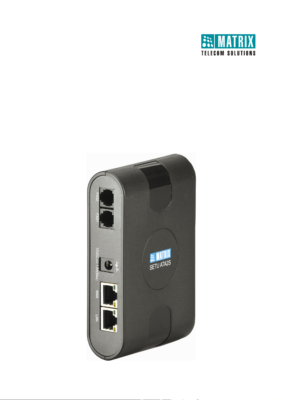
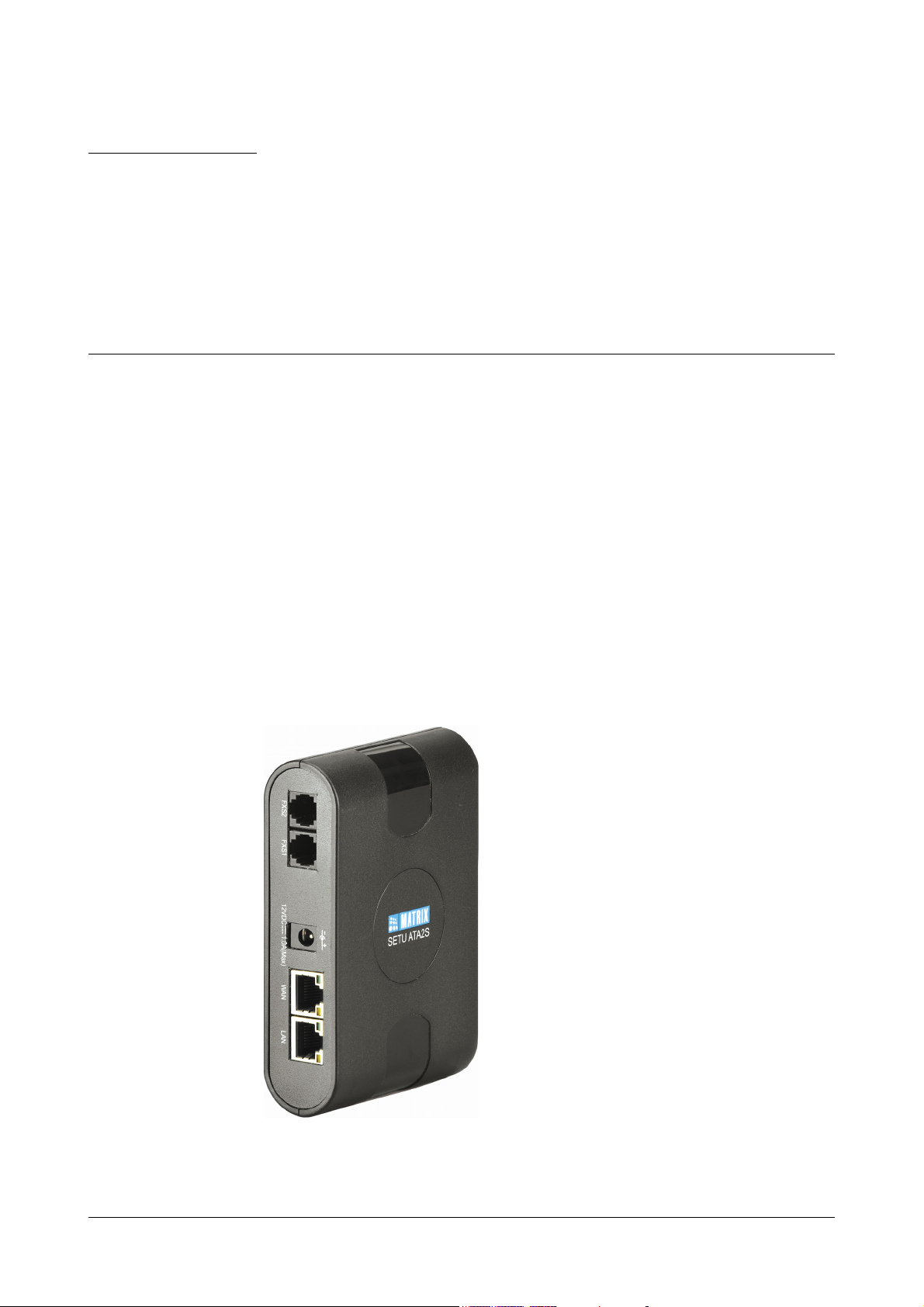
SETU ATA2S is an VoIP-FXS Adapter used as a VoIP to PSTN gateway. It allows you to make and receive voice
calls over IP Network using a conventional telephone instrument. ATA2S has two voice ports, viz. FXS and SIP.
ATA2S uses SIP (Session Initiation Protocol) protocol to make voice calls over the IP network. ATA2S converts the
voice traffic into IP packets for transmission over the internet. When you dial a telephone number, ATA2S converts
it into an IP call using the Session Initiation Protocol (SIP) and initiates a call, thereby making VoIP calls as easy as
normal telephone call.
SETU ATA2S also offers the facility of simultaneous calls and Internet browsing.SETU ATA2S can be used in
residences, small and home offices, offices of medium and large enterprises.
SETU ATA2S supports 3 SIP trunks, allowing you to subscribe with three different Internet Telephony Service
Providers or to use the SIP trunks for Peer-to-Peer Calls.
For the ease of configuration, SETU ATA2S has a an embedded, HTTP Web server with an graphic user interface,
which you can access by connecting a computer to SETU ATA2S.
Matrix SETU ATA2S System Manual 5
Page 12
Ports and Connectors
Port Name Connector Description
Power DC Jack Power Adapter, to connect 12VDC, 1.00A power adapter.
LAN RJ45 To connect a standalone computer or a LAN Switch.
WAN RJ45 To connect to the IP network over a DSL Modem or Router or a LAN Swtich
FXS1 RJ11 To connect a standard telephone instrument or a PBX.
FXS2 RJ11 To connect a standard telephone instrument or a PBX.
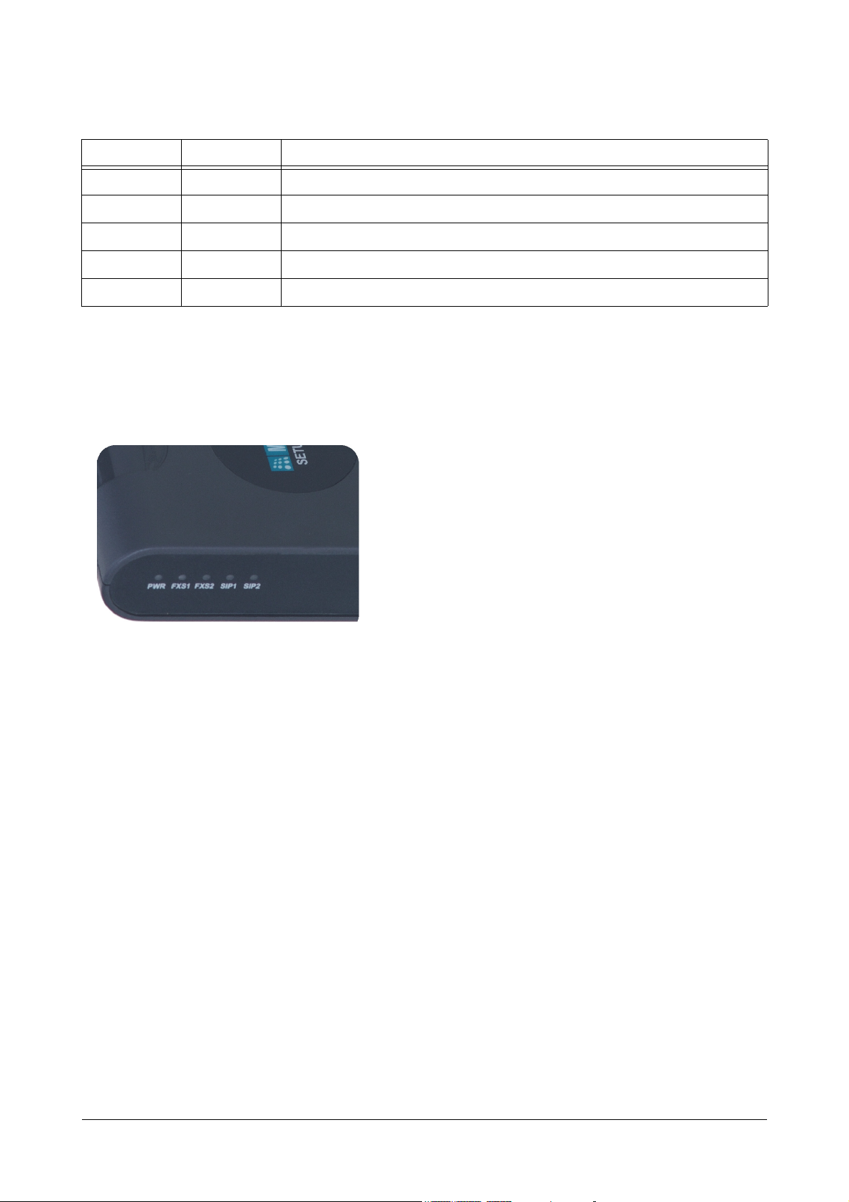
LEDs
SETU ATA2S has LEDs for each of the FXS port, the SIP Trunks (SIP1, SIP2) and POWER, to indicate the status
of the ports, and various events occurring on the ports, including errors.
6 Matrix SETU ATA2S System Manual
Page 13
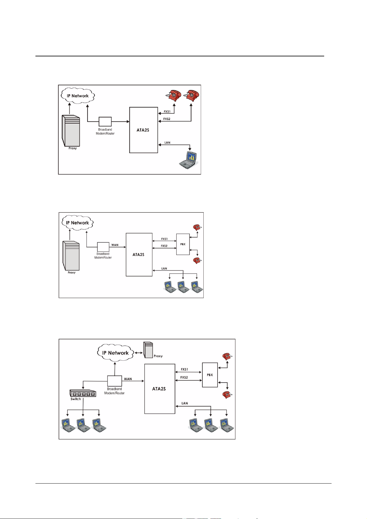
Applications of SETU ATA2S
1. Residential Application: Home users use ATA2S to make low cost calls to their relatives staying abroad.
2. SOHO Application: Small Office owners use ATA2S to make low-cost calls to their overseas customers,
employees, suppliers, etc.
3. Business Application: Corporate Offices use ATA2S to make low-cost calls to their overseas customers,
employees, suppliers, etc.
Matrix SETU ATA2S System Manual 7
Page 14
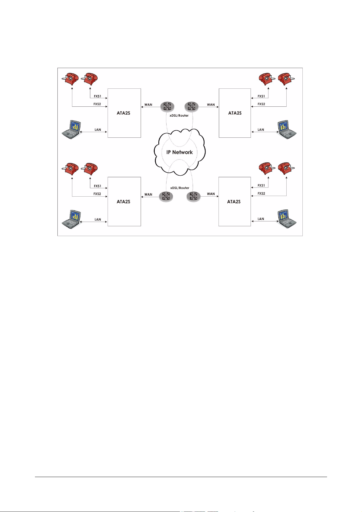
4. Peer to Peer Call Application: Corporate Offices also use ATA2S to communicate between various
branch offices free of cost.
8 Matrix SETU ATA2S System Manual
Page 15
CHAPTER 3
Getting Started
Preparing for Installation
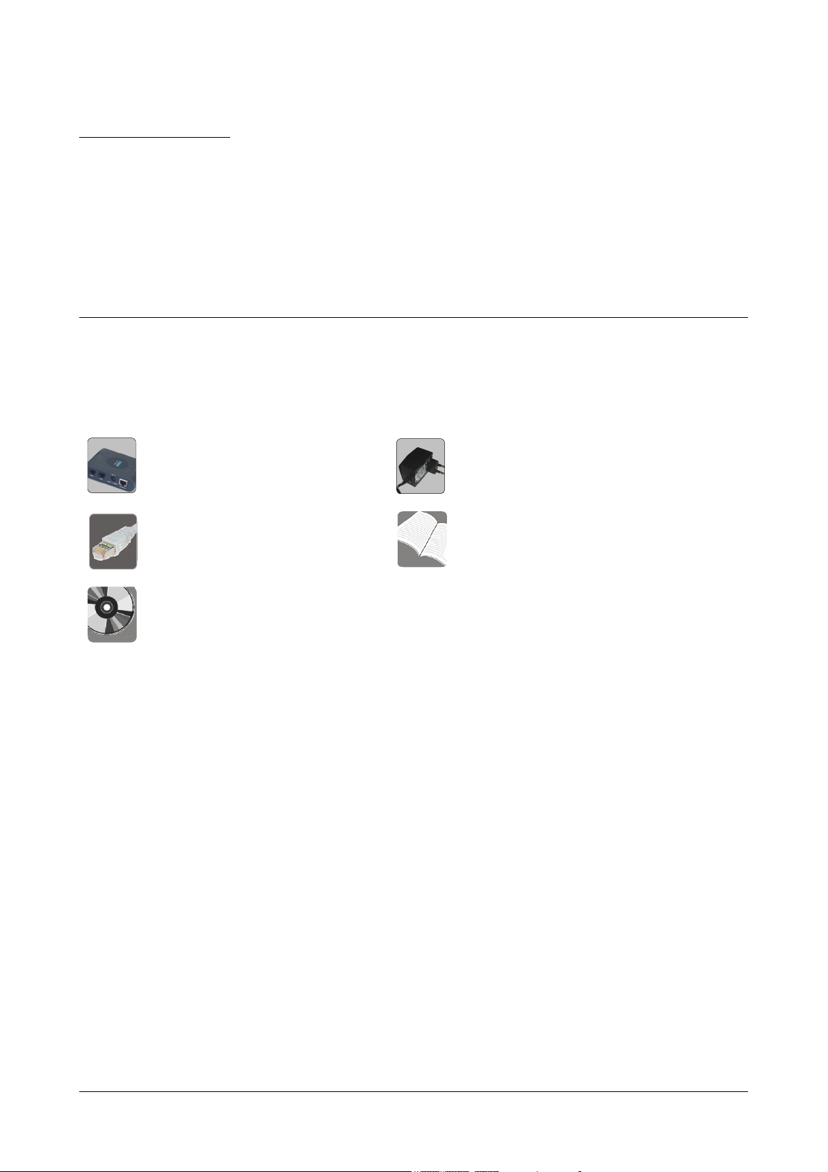
Package Contents
•SETU ATA2S
• Ethernet Cable (RJ45) • Quick Start and User Card
• CD containing System Manual,
Quick Start and User Card
1. Unpack SETU ATA2S.
2. Verify the package contents. Contact your vendor/Service Provider/system administrator, if any of the
above listed items is missing or damaged.
• Power Adapter 12V, 1Amp
(Country Specific)
• Two Screw 30/7
• Two Screw Grips
• Warranty Card Set
Protecting SETU ATA2S and Yourself
You are recommended to take the measures listed in the following protect yourself and SETU ATA2S.
Installation Precautions
Do not install the system in a place where
• it may be exposed to direct sunlight, excessive cold or humidity.
• it may be exposed to dust, water, oil, corrosive fumes.
• it may fall, causing damage to the product.
• shocks or vibrations are frequent or strong.
• there is a water source or body, like a wash basin/kitchen sink, bath-tub, a swimming pool, sprinkler, etc.
Make sure there is enough open space for ventilation at the site of installation.
Matrix SETU ATA2S System Manual 9
Page 16

Safety Instructions
Take every measure to reduce the risk of fire, electric shock and injury to the person handling this product.
• Read all the instructions given in this manual.
• Always switch off the product, unplug the product from the wall outlet when handling it. Removing covers
or opening the system or incorrect reassembly increases the risk of electric shock.
• Never open the system in power ON condition.
• Use the adapter provided with the product.
• Do not overload wall outlets and extension cords as this can result in the risk of fire or electric shock.
• Unplug the product from the wall outlet before cleaning. Do not use liquid cleaners. Use only dry and soft
cloth.
Always get your product serviced by a trained, qualified person. Contact your authorised dealer or Matrix support,
if:
• liquid has been spilled into the product or the product has been exposed to rain or water.
• the product has been dropped or the cabinet has been damaged.
• the product does not operate normally or exhibits a distinct change in performance.
Mounting the SETU ATA2S
To mount SETU ATA2S on the wall,
• Select a suitable place.
• Use the mounting template provided to you to drill holes of appropriate size and distance.
• Fix the screw grips in the holes you drilled.
• Fix the screws in the holes, leaving the screw heads protruding a few millimeters from the wall.
• Check the strength of the screws.
• Mount SETU ATA2S on the wall.
10 Matrix SETU ATA2S System Manual
Page 17
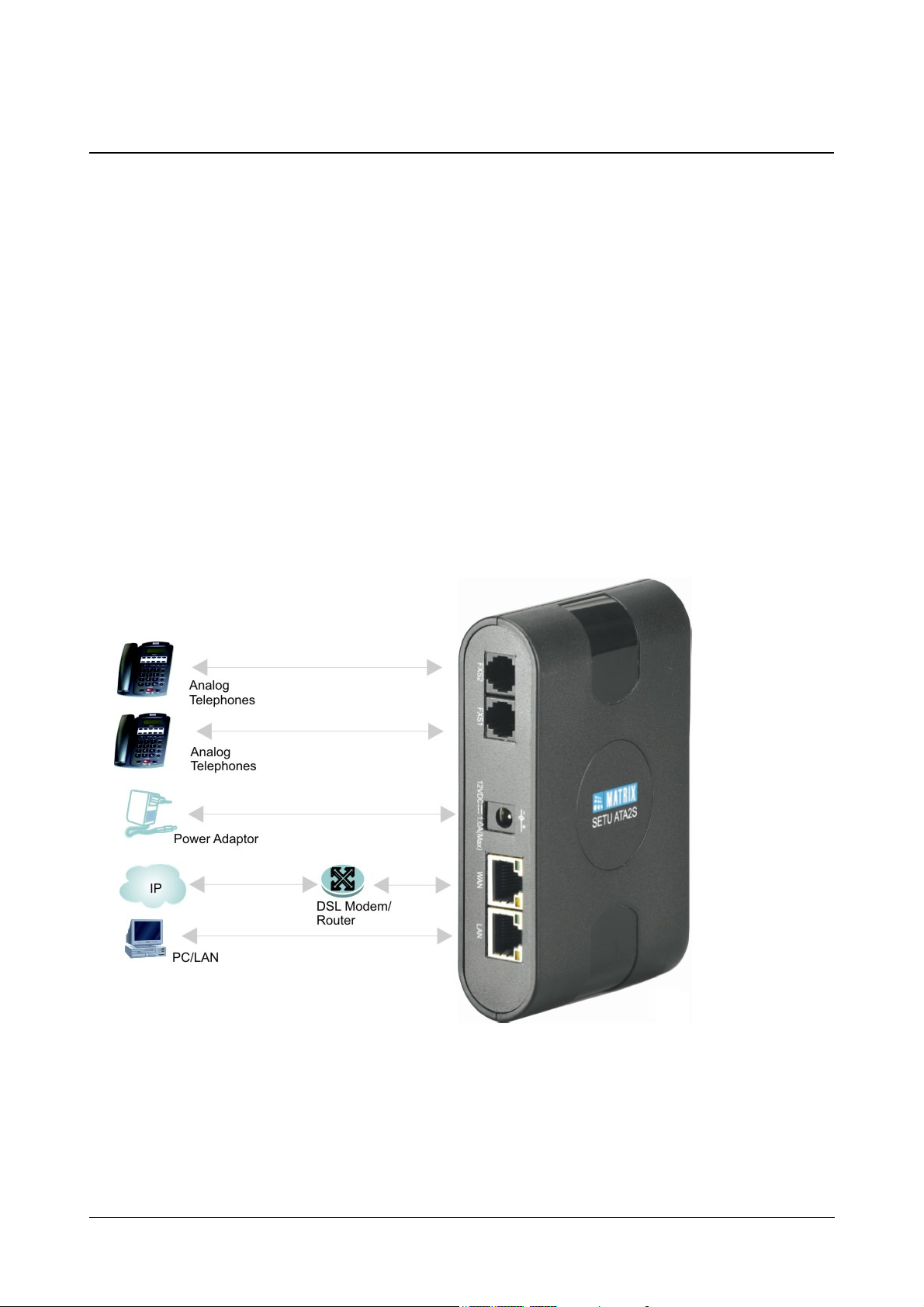
Connecting SETU ATA2S
• Connect a standalone computer/ LAN Switch to the LAN Port of SETU ATA2S using an Ethernet cable.
• Connect the WAN Port of SETU ATA2S to the IP Network—a DSL modem or Router or a LAN
Switch—using the Ethernet cable provided to you.
• Connect a telephone to both the FXS Ports of SETU ATA2S, using a standard telephone cable with an
RJ11 plug.
OR
You may also connect a PBX to both the FXS ports of SETU ATA2S.
• Connect the power adapter provided with SETU ATA2S to the power jack labeled 12VDC-1A(MAX).
• Connect the adapter plug into a power outlet.
• Switch ON power.
• Wait for the Reset Cycle to complete.
Reset Cycle
• At Power ON,
• POWER LED will glow Green, continuously.
• All LEDs—FXS1, FXS2, SIP1 and SIP2 —will blink Red thrice (250 ms On - 250 ms Off).
Matrix SETU ATA2S System Manual 11
Page 18

• On successful completion of initialization cycle, each LED will glow as per the call conditions
summarized in the table below.
LED Indication Meaning
FXS1 Continuously ON FXS port is either OFF-hook or in speech during the incoming/
outgoing call.
Blinks fast 200ms ON,
FXS port is in Error state during incoming/outgoing call.
200ms OFF
Blinks slow 500ms ON,
500ms OFF
FXS port is Ringing for incoming call or Number is being dialed for
the outgoing call (After end of dialing).
Continuously OFF FXS port is in ON-Hook.
FXS2
Continuously ON FXS port is either OFF-hook or in speech during the incoming/
outgoing call.
Blinks fast 200ms ON,
FXS port is in Error state during incoming/outgoing call.
200ms OFF
Blinks slow 500ms ON,
500ms OFF
FXS port is Ringing for incoming call or Number is being dialed for
the outgoing call (After end of dialing).
Continuously OFF FXS port is in ON-Hook.
SIP1 Continuously ON SIP1 is enabled and is registered with the SIP server or 'Active'
status of SIP trunk.
Blinks fast 200ms ON,
200ms OFF
Blinks slow 500ms ON,
500ms OFF
SIP1 is enabled but not registered with the SIP server (when SIP
trunk is configured as proxy).
SIP1 is enabled but not registered with the SIP server (when SIP
trunk is configured as Peer-to-Peer).
Continuously OFF SIP1 is disabled.
SIP2 Continuously ON SIP2 is enabled and is registered with the SIP server or 'Active'
status of SIP trunk.
Blinks fast 200ms ON,
200ms OFF
Blinks slow 500ms ON,
500ms OFF
SIP2 is enabled but not registered with the SIP server (when SIP
trunk is configured as proxy).
SIP2 is enabled but not registered with the SIP server (when SIP is
configured for Peer-to-Peer calling).
Continuously OFF SIP2 is disabled.
You can also view the status of the ports on the Status page of the web-based graphical user interface of SETU
ATA2S. See the topic “System Status”.
12 Matrix SETU ATA2S System Manual
Page 19

Configuring SETU ATA2S
SETU ATA2S provides access to system configuration at two levels: Admin and User. A distinct set of features and
facilities can be configured at each of these levels.
SETU ATA2S can be configured using its Web-based graphic user interface (GUI) and from the phone connected
to its FXS port. While the entire system configuration can be done using the GUI, you can configure only certain
parameters from the phone.
Admin Mode
Admin is defined as the person who installs, configures and maintains the SETU ATA2S. In the Admin mode, you
have full access to system configuration, all configurable parameters, features and facilities, and system
maintenance:
• Basic Settings
• Advanced Settings
• Supplementary Services
Access to Admin mode is protected by a password. The default Admin Password is 1234. The password may be
changed.
User Mode
In the User mode, you can configure specific features and facilities of SETU ATA2S, as listed below:
• Supplementary Features
• Speed Dialing
• Network parameters
• User Password
• Syslog (debug)
• Factory Defaults
•PCAP
Access to the User mode is also protected by a password, referred to as the User Password. The default User
Password is 1234. The password may be changed.
Configuration using Web-based GUI: Jeeves
SETU ATA2S has a graphic user interface (GUI), Jeeves, an easy-to-use proprietary software of Matrix for system
configuration. Jeeves is an embedded, HTTP web server which you can access from the computer you connected
to the LAN Port or the WAN port of SETU ATA2S.
Jeeves allows system configuration in the Admin mode and User mode.
To access Jeeves, follow these steps:
• Connect a standalone computer to the LAN port of SETU ATA2S. The LAN Port of SETU ATA2S and that
of the computer must be in the same Subnet.
The default IP Address of the LAN port of SETU ATA2S is: 192.168.002.1
The default Subnet Mask of the LAN port of SETU ATA2S is: 255.255.255.0
If required, change the IP Address and the Subnet of the computer.
Matrix SETU ATA2S System Manual 13
Page 20
You may also connect the LAN port of SETU ATA2S to a computer on LAN. If you connect the LAN port of
SETU ATA2S to a LAN Switch, make sure that the IP Address of LAN port of SETU does not conflict with
the IP Address of any device on the LAN, and SETU ATA2S is in the same Subnet as the LAN computer.
You may change the IP Address and Subnet Mask of the LAN Port of SETU ATA2S by dialing the relevant
System Commands from the phone connected to the FXS port of SETU ATA2S. See the topic “Configuring
using a Phone”.
When installing the system for the first time, you are advised to connect SETU ATA2S to a standalone
computer only.
• Make sure a web-browser, either Internet Explorer 7 or Mozilla Firefox, is installed on the computer.
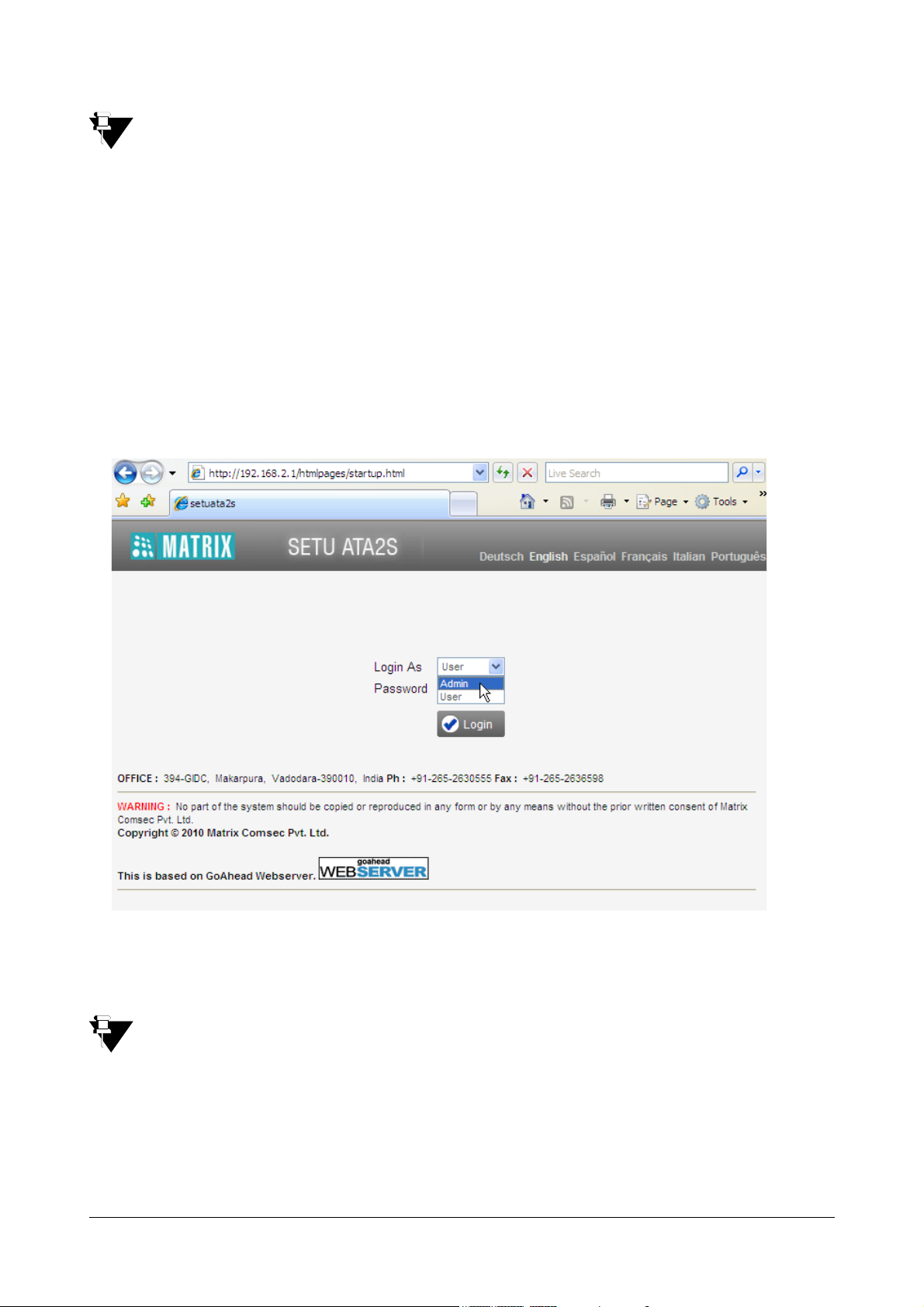
• Open the browser on the computer.
• Type 192.168.002.1, the default IP address of the LAN port of SETU ATA2S, in the address bar of the
browser and press Enter key/click Go.
If you have connected SETU ATA2S to the LAN and have changed the IP Address of the LAN port of
SETU ATA2S, enter the current IP Address in the address bar of the browser.
The Login page of Jeeves opens.
You can also use the WAN Port of SETU ATA2S to access the embedded web server in the same manner.
The default IP Address of the WAN Port of SETU ATA2S is: 192.168.001.151
The default Subnet Mask of the WAN Port of SETU ATA2S is: 255.255.255.0
You are offered two Login modes: Admin and User.
14 Matrix SETU ATA2S System Manual
Page 21
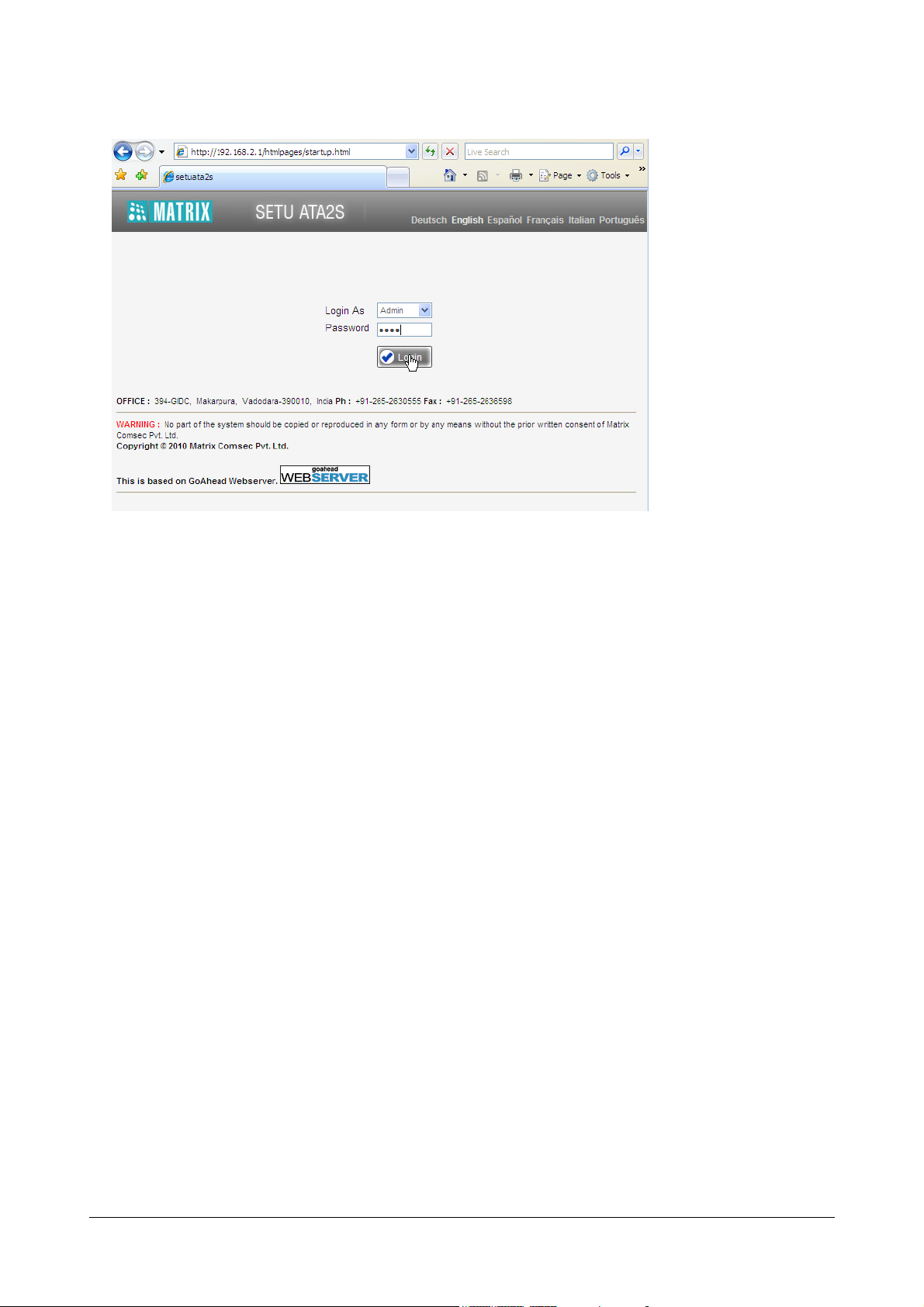
To log in as Admin,
• In the Login as box, select Admin.
• In the Password field, enter 1234, the default Admin Password.
• Click the Login button.
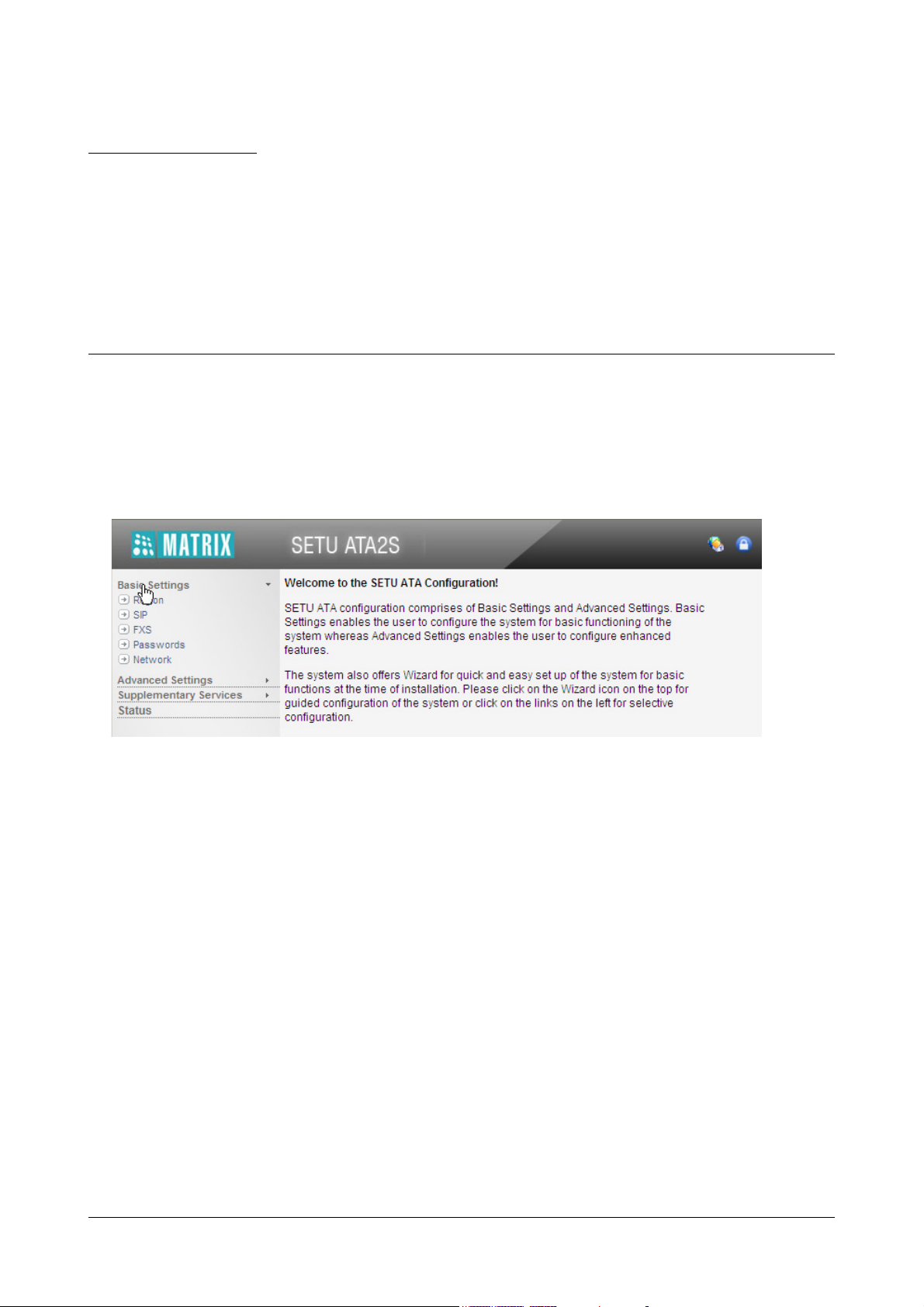
• On successful login, the Admin mode page will open.
• The left pane shows the links Basic Settings, Advanced Settings, Supplementary Services, and
Status.
Basic Settings are sufficient to get your SETU ATA2S into operation.
• Click the links to expand.
Matrix SETU ATA2S System Manual 15
Page 22
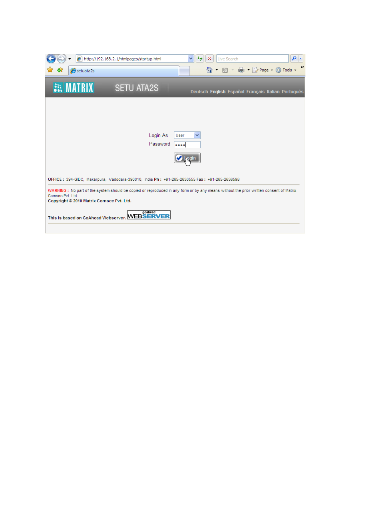
To log in as User,
• In the Login as combo box, select User.
• In the Password field, enter 1234, the default User Password.
• Click the Login button.
• On successful login, the User mode page will open.
• The left pane displays the User Settings and Status links.
• Click the User Settings link to expand. The sub-links to the functions and features that are allowed
to be configured from the User mode appear on the left pane: Supplementary Features, Speed
Dialing, Network, User Password, Syslog, and Factory Defaults.
• Click the Status link to view the status of the system and the ports.
Configuring using a Phone
You can enter the Admin mode and the User mode using the phone connected to the FXS Port of SETU ATA2S,
and change feature settings, and certain network parameters like the IP Address and Subnet Mask of the LAN and
the WAN port of SETU ATA2S, select the Connection Type (IP Addressing) by dialing “System Commands” from
the phone connected to the FXS port of SETU ATA2S.
You can also dial System Commands to view the current IP Addresses of the WAN and LAN Ports (if your phone
has a display).
16 Matrix SETU ATA2S System Manual
Page 23

Follow the instructions given below to configure the system from the phone.
Admin Mode
• Lift the receiver of the phone.
•Dial #19 to enter the Admin mode.
• Dial the Admin Password (default: 1234).
You will get programming tone.
• Dial the System Command for the feature/facility you want to configure.
For example:
To change IP Address of the LAN Port to 192.168.1.120, dial 12192168001120#*
• When you dial a valid command, SETU ATA2S plays a confirmation tone for 3 seconds, and plays the
programming tone.
•Dial 0 to exit configuration mode.
When network parameters are changed, SETU ATA2S will restart, without dial tone/confirmation tone.
You can also view the Network parameters (IP Address, Subnet Mask, Connection Type, etc.) on the phone’s
display. See ‘“System Status”.
For a complete list of commands, refer “System Commands” in the Appendix.
User Mode
• Lift the receiver of the phone.
•Dial #18 to enter the User mode.
• Dial the User Password (default: 1234).
• You will get programming tone.
• Dial the command for the feature/facility you want to configure.
For example,
The command for configuring the destination number for Call Forward-Unconditional is: 51-Destination
Number-#*
To configure 2001 as the destination number for Call Forward-Unconditional, dial 512001#*.
•Dial 0 to exit programming mode.
For a complete list of commands, refer “System Commands” in the Appendix.
Matrix SETU ATA2S System Manual 17
Page 24

18 Matrix SETU ATA2S System Manual
Page 25
CHAPTER 4
The Basic Settings enable you to configure SETU ATA2S for basic functions. As Basic Settings cover much of your
configuration requirements, you will be able to operate and use the system efficiently, when you configure Basic
Settings.
• Click Basic Settings link.
The links to the different basic parameters appear on the left pane.
Basic Settings
There are two ways to configure Basic Settings:
• Using the Wizard. The Wizard will guide you step-by-step through the configuration.
OR
• Selectively configuring the Basic Settings parameters, by clicking the links on the left pane.
To use the Wizard,
Matrix SETU ATA2S System Manual 19
Page 26
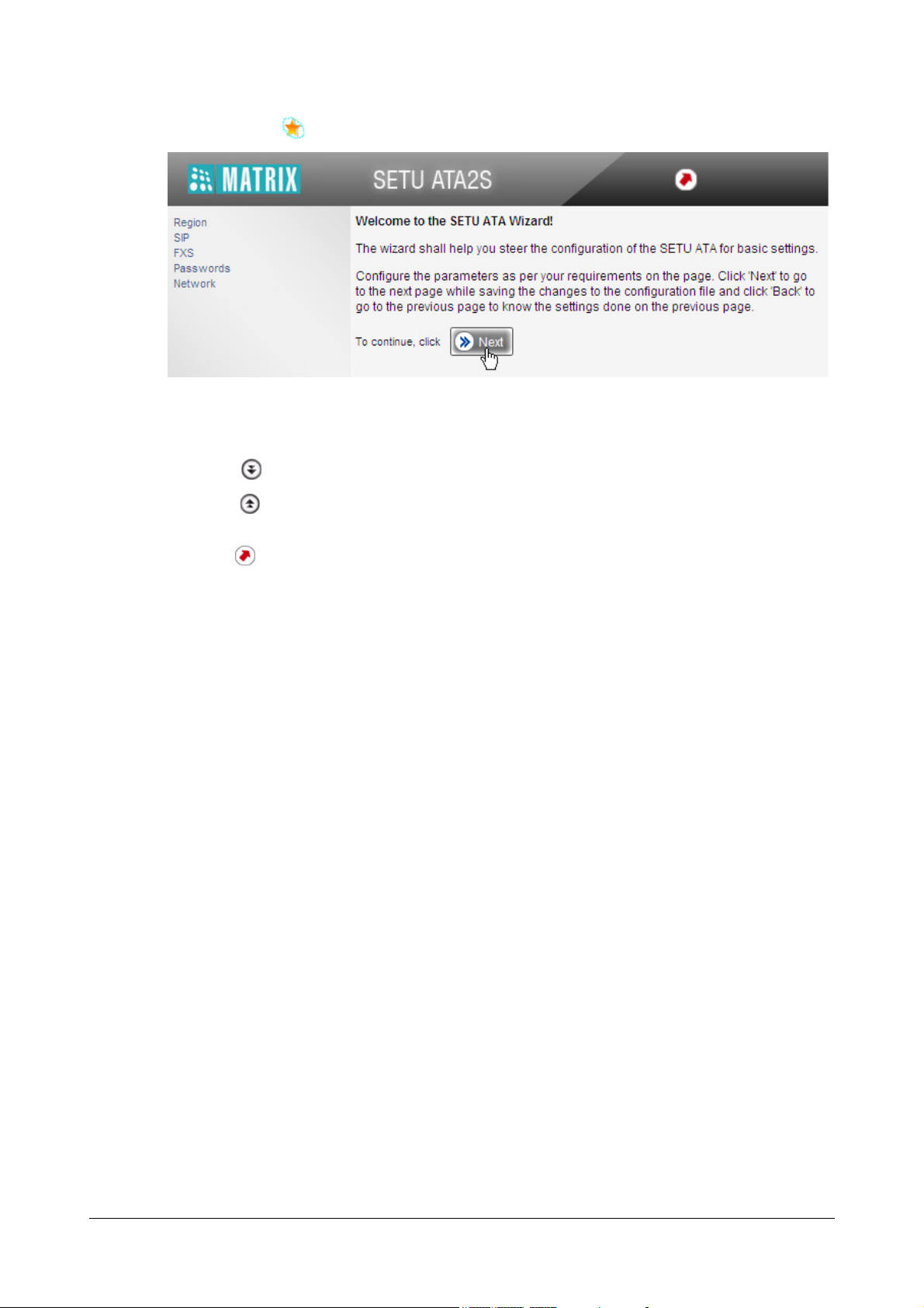
• Click the Wizard icon on the top right of your screen.
• The Next button takes you to the next page, saving the changes you made on the current page.
• The Back button returns you to the previous page.
• The More button expands parameters on the page.
•The Less button collapses parameters on the page.
• The Default button assigns factory set values to all the parameters on the page.
• The Quit button allows you to exit the Wizard at any stage, saving changes you made before
exiting.
To use selective configuration,
• Click Basic Settings link to expand.
• Click each parameter link, Region, SIP, FXS, Passwords, Network.
• The selected parameter page opens.
• The More button expands parameters on the page.
•The Less button collapses parameters on the page
• Set the desired values on the page.
• Click Submit to save your settings on the page.
You may use the Wizard or selectively configure the Basic Settings pages, whichever works best for you.
The instructions provided in this chapter, describe selective configuration of the Basic Settings pages.
1. Click Basic Settings to expand.
2. The following links appear under Basic Settings:
• Region
•SIP
•FXS
• Passwords
•Network
Each of these are explained in detail in the following.
20 Matrix SETU ATA2S System Manual
Page 27
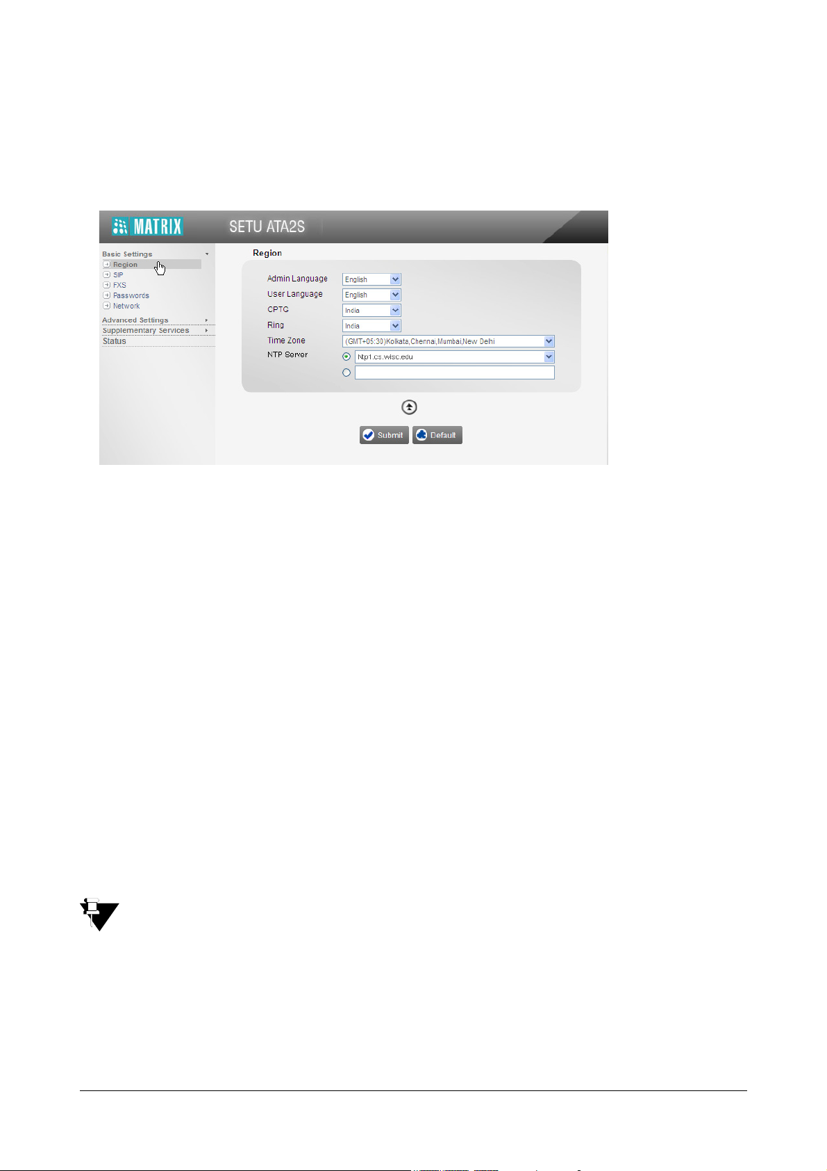
Region
1. Click Region.
2. Click More button to view all parameters on the page.
3. Select Admin Language and User Language. Default: English.
SETU ATA2S can display the Admin and User pages of the GUI, Jeeves, in the following languages:
• English
•Italian
• Spanish
• French
•German
• Portuguese
All the Admin and User Pages of the GUI will appear in the language you selected, when you login again
as Admin or User.
You can also select a Language on the Login page; however, it will be applied for the current session only.
4. Select CPTG (Call Progress Tone Generation) to match the CPTG of the country where SETU ATA2S is
installed. Default: India.
The SETU ATA2S supports country specific Call Progress Tones Generation (CPTG) to simulate the same
tones of the local PSTN to which it is connected. The CPTG supported by SETU ATA2S for different
countries are presented in the “Appendix”.
When you reset SETU ATA2S to factory defaults, CPTG you selected will not be set to default.
5. Select Ring cadence to match the ring cadence of the country where SETU ATA2S is installed. Select
your country from the drop down list. Default: India.
During an incoming call, SETU ATA2S will play the ring over the SLT as per the Ring Cadence of the
country you selected. For a complete list of Ring Cadences of different countries supported by SETU
ATA2 S , s ee “Appendix”.
Matrix SETU ATA2S System Manual 21
Page 28

When you reset SETU ATA2S to factory defaults, the Ring you selected will not be set to default.
6. To synchronize Date and Time of SETU ATA2S with that of the country where it is installed, select Time
Zone from the drop down list. Default: (GMT+05:30) Kolkata, Chennai, Mumbai, New Delhi.
7. To use a public internet time server for date and time synchronization, select an internet based time server
as NTP Server. You may select any of the three reliable public internet time servers
1
supported by SETU
ATA2 S:
• ntp1.cs.wisc.edu
• time.windows.com
• time.nist.gov
Default: Ntp1.cs.wisc.edu
If you want to use an NTP server other than these, select the radio button and enter the IP Address/
domain of the server in the empty field.
When you reset SETU ATA2S to factory defaults, Date and Time settings will not be set to default.
8. Click Submit to save your region settings.
1. You can select from three free, reliable public internet time servers run by the University of Wisconsin-Madison, Microsoft, and the
National Institute of Standards and Technology (NIST), to obtain date and time. You can also configure an NTP time server of your
preference, other than these. These public internet time servers provide time offset from the Greenwich Mean Time (GMT), and you
can select the time according to the time zone of the country you are installing the SETU ATA2S. For instance, if your ATA2S is
installed in India, you can select the time zone for India (GMT+5.30 Calcutta, Chennai, Mumbai, and New Delhi). The time for India is
offset from GMT by +5.30 hours. Similarly, if your ATA2S is installed in Hawaii, select the time zone for Hawaii, which is offset by GMT
-10:00 hours, to set the correct time and date.
22 Matrix SETU ATA2S System Manual
Page 29
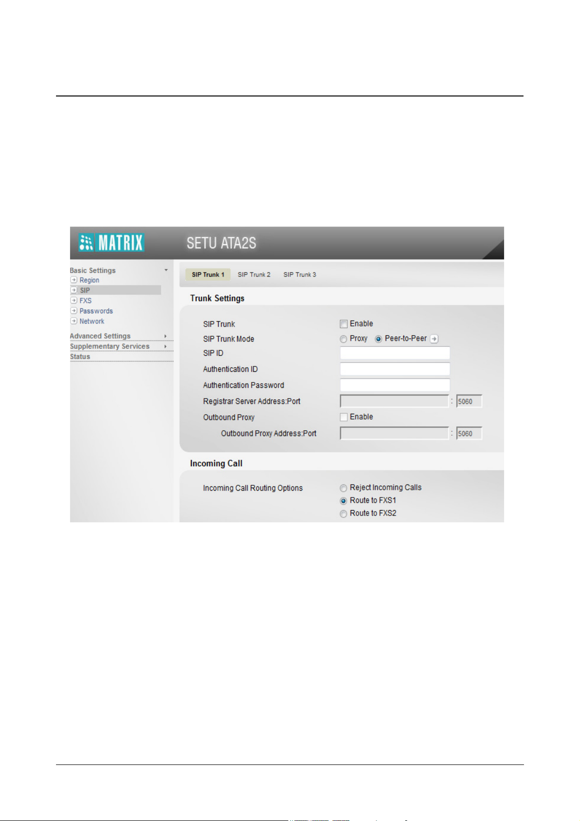
SIP Trunks
SETU ATA2S supports three SIP trunks, which may be configured as Proxy or Non-Proxy, i.e. Peer-to-Peer trunks.
You may register with three different ITSPs and use their services.
1. Click the link SIP.
The parameters of SIP Trunk 1 appear on your screen.
2. Click More button to view all parameters of SIP Trunk 1 on this page.
Matrix SETU ATA2S System Manual 23
Page 30
Trunks Settings
1. Select the check box Enable to use the SIP Trunk. Default: Disabled.
You may disable the SIP trunk, if you do not want to include it in Call Routing.
2. Select SIP Trunk Mode according to your installation. Default: Peer-to-Peer.
• Select Proxy, if you want to register this SIP trunk with an ITSP or a Registrar Server.
• Select Peer-to-Peer, if you want to use the trunk for Peer-to-Peer (non-proxy) calls.
If you select Peer-to-Peer, you must also configure the number strings in the Peer-to-Peer Table.
24 Matrix SETU ATA2S System Manual
Page 31

• Click the arrow icon to configure the Peer-to-Peer Table. A new window opens.
• You can configure as many as 500 number strings, which are stored against an Index number.
• In the Number field, enter the peer-to-peer number string—prefix or entire number—that will be
dialed. The number string must not exceed 24 characters. Default: Blank.
If the number to be dialed out is <dialednumber@destination address>, for example,
123@abc.com, you must enter 1234 in this field.
• To identify the number string you configured, enter a name in the Name field. It may be the name of
your contact or any name you wish to assign to the number string. The name may consist of 24
characters (maximum). Default: Blank.
•As Minimum Digits, define the minimum length of the number string that must be dialed for the
system to consider it as a valid number. Default: 01.
Matrix SETU ATA2S System Manual 25
Page 32

If the peer-to-peer number string you dial is shorter than the Minimum Digits you have configured,
the system will not dial out the number.
•As Maximum Digits, define the maximum length of the number string that must be dialed out for
the system to consider it the complete number string. Default: 24.
If the peer-to-peer number string you dial is longer than the Maximum Digits you have configured,
the system will strip off the additional digits and dial out the number.
• In the Destination Address field, enter the domain name or IP Address to where the dialed peer-
to-peer number string is to be sent. The Destination Address may consists of up to 40 characters.
Default: Blank.
For example, if the peer-to-peer number to be dialed out is 123@abc.com, enter abc.com as
Destination Address. If the number is 1234@ 192.168.1.197, enter 192.168.1.197 as the
Destination Address. The Destination Address can also be in the form of Address: Port number.
• the Click Submit to save entries.
• Close the window.
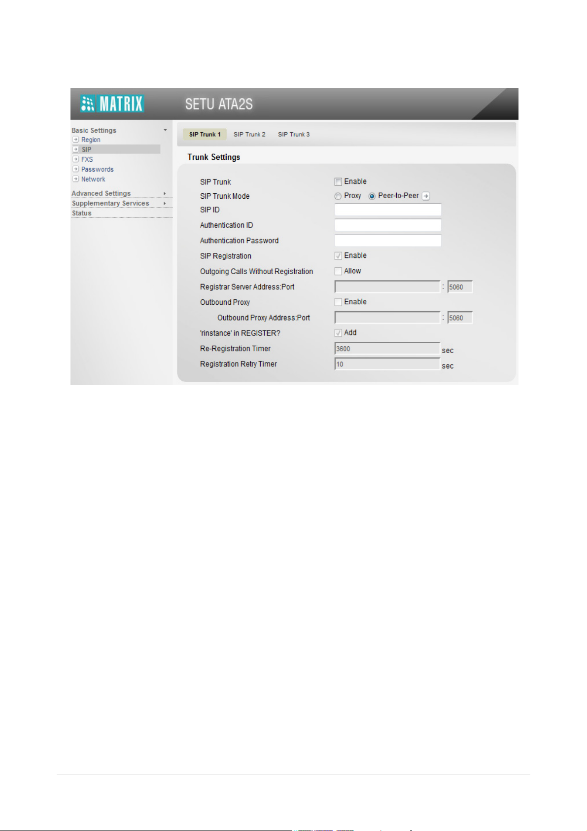
3. Enter the SIP ID. This is the ID which remote parties will use to call this SIP Trunk. Default: Blank.
The SIP ID may be a number or text consisting of a maximum of 40 characters.
If you have defined the trunk mode as Proxy, enter the SIP ID provided by your ITSP. For example, if SIP
URI provided by the ITSP is 12345@abc.com, enter 12345 in this field.
If you have defined the trunk mode as Peer-to-Peer, enter the desired SIP ID.
4. Enter Authentication ID. Default: Blank.
If you have defined the SIP trunk mode as Proxy, enter the Authentication ID (User ID) provided by your
ITSP
If you have defined the trunk mode as Peer-to-Peer, enter the ID of your preference as Authentication ID.
5. Enter Authentication Password. Default: Blank.
If you have defined the SIP trunk mode as Proxy, enter the Authentication Password provided by your
ITSP.
If you have defined the trunk mode as Peer-to-Peer, enter a password of your preference as
Authentication Password.
6. SIP Registration is applicable for Proxy SIP Trunks only. Default: Enabled.
SETU ATA2S will send the REGISTER message to Registrar proxy or Outbound proxy as applicable.
Clear the check box to disable.
7. Select the OG Calls without Registration check box to allow the users to make outgoing calls
irrespective of whether the SIP Trunk has been successfully registered with proxy or not.
26 Matrix SETU ATA2S System Manual
Page 33

By default, the system does not allow outgoing calls to be made if the status of the SIP trunk is 'not
registered'.
8. If you have defined the SIP trunk mode as Proxy, in the Registrar Server Address: Port field, enter the
Registrar Server Address and the Registrar Server’s listening port for SIP messages.
The registrar server address may be an IP address or a domain. Default: Blank.
The valid port range is: 1024-65534. Default: 5060.
9. If your service provider uses an outbound proxy for handling voice calls, enable Outbound Proxy check
box.
• In the Outbound Proxy Server Address: Port field, enter the IP address or domain name of the
Outbound Proxy Server and the number of the Outbound Proxy Server’s Listening Port for SIP.
The Server Address may consist of maximum 40 characters. Default: Blank.
The valid range for the port is 1024-65534. Default: 05060.
10. To add ‘rinstance’ in the REGISTER Message, keep this feature enabled. Default: Enabled.
‘rinstance’ is any random value which can be used by the SETU ATA2S to fetch its own contact binding,
i.e. to know the Registration Expiry Timer assigned by the server.
When you enable ‘rinstance’ in Register, SETU ATA2S will generate any random value of 'rinstance' and
include in the REGISTER message. The system will use the registration expiry timer of that contact
binding.
11. Set the Re-registration Timer. This is the time period after which the SETU ATA2S will send registration
request to maintain registration binding with the Registrar server.
The valid range of this timer is 00001- 65535. Default: 3600 seconds.
12. Define the Registration Retry Timer. When a registration attempt fails, SETU ATA2S will resend
registration request to the Registrar Server after the expiry of the Re-registration Timer. The valid range of
this timer is from 00001- 65535. Default: 10 seconds.
13. Click Submit.
Matrix SETU ATA2S System Manual 27
Page 34

Incoming Call
1. Select an appropriate Incoming Call Routing option for the SIP Trunk. You may select: Default: Route To
FXS1.
• Reject Incoming Calls: The system will reject all calls received on the SIP Trunk. Select this option, if
you want to block calls on this SIP trunk.
• Route To FXS1: The system will place all calls received on the SIP Trunk on the FXS1 port. The phone
connected to the port will start ringing for the duration of the Ring Timer (default: 45 seconds). If the call
is not answered within this timer, it will be rejected.
Select this option, if SETU ATA2S is being used as a standalone device.
• Route To FXS2: The system will place all calls received on the SIP Trunk on the FXS2 port. The phone
connected to the port will start ringing for the duration of the Ring Timer (default: 45 seconds). If the call
is not answered within this timer, it will be rejected.
Select this option, if SETU ATA2S is being used as a standalone device.
• Route to Both: The system will place all calls received on the SIP Trunk on both the FXS ports
simultaneously. Both the phones connected to ports will start ringing for the duration of the Ring Timer
(default: 45 seconds). If the call is not answered within this timer, it will be rejected.
When the call is answered by any FXS port, the call will connect to the caller and other FXS port shall
stop ringing.
Select this option, if SETU ATA2S is being used as a standalone device.
Answer the call, collect number and route to FXS1: Select this option, if SETU ATA2S is connected
to a PBX and you want callers to reach extensions of the PBX by simply dialing the extension number.
The system will first answer the call on the SIP trunk, and play dial tone to the caller. When the caller
dials the number, it will collect the digits and route the call from its FXS1 port to the extension of the
PBX.
• Answer the call, collect number and route to FXS2: Select this option, if SETU ATA2S is connected
to a PBX and you want callers to reach extensions of the PBX by simply dialing the extension number.
The system will first answer the call on the SIP trunk, and play dial tone to the caller. When the caller
28 Matrix SETU ATA2S System Manual
Page 35

dials the number, it will collect the digits and route the call from its FXS2 port to the extension of the
PBX.
2. SETU ATA2S supports display of Calling Line Identity (CLI) received in the SIP request message on the
FXS port. To display CLI Number on FXS Port, you may select:
• Calling Number
• Called Number
Default: Calling Number.
3. Define the type of response the system should send on the receipt of an incoming call on the SIP trunk.
For the On Connecting Media, Send parameter, you may select:
• 183 Session Progress
• 200 OK
Default: 183 Session Progress
4. If you want to allow incoming calls on the SIP Trunk only after callers have authenticated themselves with
their User ID and Password, enable Digest Authentication. Default: Disabled.
If you enable Digest Authentication feature on the SIP trunk, you must configure the Digest Authentication
Table. To do this,
• Click the arrow icon.
Matrix SETU ATA2S System Manual 29
Page 36

• The Digest Authentication Table page opens in a new window.
• Enter the User ID to be authenticated along with its corresponding Password against each Index in
• If you have finished entering the User IDs and their corresponding User Passwords in this Table,
• Close the window.
Vocoders
the Table.
The User ID may be a maximum of 40 characters. The User Password may be a maximum of 16
characters.
click Submit.
To know more about this feature, see “Digest Authentication”.
1. Select Vocod ers in the order of preference from the multiple selection box.
30 Matrix SETU ATA2S System Manual
Page 37

Vocoders are the various voice codecs used to compress the data in RTP packets for optimum use of
bandwidth and for ensuring voice quality. You can set 4 Vocoder options in the order of preference.
The Vocoders supported by SETU ATA2S in the order of preference, i.e. 1st to 4th, listed in the Used
Codecs box are:
• G.711 A - Law
•G.711 Law
• G.729
• G.723
• To remove a Vocoder from this list, select the Vocoder and the back arrow <
• The Vocoder will be moved to the Unused Codecs box.
• Select the required Vocoders from the right list box with your cursor.
• Use the Up and Down arrows near the Used Codecs box to change the order of Vocoder preference.
2. If you have G.723 as a Preferred Vocoder, select G.723 Bit Rate as: 5.3 Kbps or 6.3 Kbps. Default:
6.3kpbs.
When G.723 is negotiated, the selected Bit Rate will be applied only when sending the RTP packets.
When receiving RTP packets from the remote end, both Bit Rates of G.723 will be accepted.
Advanced
1. Select the default SIP Transport for outgoing SIP messages from the following options:
• UDP: Outgoing messages are transported using UDP.
• TCP: Outgoing messages are transported using TCP.
Matrix SETU ATA2S System Manual 31
Page 38

• TCP (Fallback to UDP): TCP is used for outgoing messages. However, if the TCP connection fails, the
system will attempt to send the message again over UDP.
Default: UDP
To use TCP or TCP (Fallback to UDP), to must enable SIP over TCP in the “System Parameters” page.
2. Select the Automatic Number Translation check box, if you want to apply this feature on the SIP trunk.
Default: Disabled.
Automatic Number Translation (ANT) of SETU ATA2S modifies the number strings—entire numbers or
part thereof—you dial into number strings understood by the IP network.
The ANT feature is useful when the network requires adding or stripping off of parts of the dialed number
strings. For example, the PSTN requires you to dial the prefix 00 for calling international numbers,
whereas the ITSP you have subscribed this SIP trunk restricts the dialing of the prefix 00 for international
numbers. If you happen to dial this prefix, your call will be rejected by the ITSP.
ANT is also used when SETU ATA2S is deployed for networking between PBXs at multiple sites, and
“Multi-Stage Dialing” is required.
To use ANT, select the check box and configure the Automatic Number Translation Table. To do this,
• Make a list of numbers that need to be modified before being dialed out from this SIP trunk. Make a list
of the corresponding modified numbers that the system should substitute the dialed numbers with.
• Click the arrow icon.
32 Matrix SETU ATA2S System Manual
Page 39

• The Automatic Number Translation table opens in a new window.
In this table, you can store as many as 24 Dialed Numbers and their corresponding Substitute
Numbers, at Index Numbers 01 to 24.
In the Dialed Number column, enter the numbers that need to be modified when dialed out from this
SIP trunk.
• In the Substitute Number column, enter the numbers which the system should dial out in place of the
dialed numbers.
Make sure you enter a Dialed Number and its corresponding Substitute Number at the same Index
number in the table. For example, if you entered 001 as Dialed Number at Index 01, you must enter its
corresponding Substitute Number 1 also at Index 01.
• Click Submit to save your entries.
• Close the window.
3. By default, the CLI of the SIP Trunk is sent to the called party when outgoing calls are made using the SIP
trunk. If you do not want to send CLI, enable the CLIR check box. Default: Disabled.
4. If you want the system to reject incoming calls which do not have the identity of the caller (Calling Party
Information), enable the Anonymous Call Rejection check box. Default: Disabled
5. If you want the system to send RTP packets to original IP and Port from where RTP packets are received,
by ignoring the contact information received in SDP, enable the Symmetric RTP check box. Default:
Disabled
6. If you want the system to send DNS SRV query to the configured domain server, enable DNS SRV. When
disabled, the system will send DNS A query to the configured domain server. Default: Disabled.
Matrix SETU ATA2S System Manual 33
Page 40

7. When the system is installed behind a NAT Router, select specific NAT traversal mechanism to be used as
NAT Type. Default: Disabled.
• Select Router’s IP Address, if your ATA is located behind the NAT router (any type).
Make sure you disable Outbound Proxy on SIP trunk and configure the same IP Address under NAT
settings in the “System Parameters” page.
• Select STUN if your ATA is located behind the NAT router other than Symmetric.
Make sure you disable Outbound Proxy on SIP trunk and configure the STUN Server Address and port
in “System Parameters”.
8. Select the appropriate DTMF sending/receiving mechanism that is compatible with the DTMF sending/
receiving mechanism of your ITSP or remote peer. SETU ATA supports:
• Inband
• Outband
• SIP (INFO)
Default: Outband
• In the On Time field, set the time for which the DTMF digit should remain on, when the digit is dialed
out by the system. The DTMF On Time may be 100 or 150 or 200 milliseconds. Default: 100
milliseconds.
• In the Off Time field, set the time for which system should wait before dialing the successive DTMF
digits. The DTMF Off Time may be 100 or 150 or 200 milliseconds. Default: 100 milliseconds.
9. Configure the Pause Timer (sec), if you want to insert a delay before the digits of a number string are out
dialed from the SIP trunk.
The Pause Timer is typically used in “Multi-Stage Dialing”. The range of the Pause Timer is from 1 to 9
seconds. Default: 2 seconds.
10. Select an appropriate Call Hold Method that is compatible with your ITSP proxy server/remote peer.You
may select:
• RFC 2543
• RFC 3261
Default: RFC 3261
11. To send and receive the Fax over IP from and on the FAX machine connected to FXS port of the SETU
ATA2S, select the desired Fax over IP protocol:
• T.38(UDPTL): If you select this option, the device you are sending the fax to, must also support this
protocol.
• Pass Through: Select this option if you need to send fax over G.711. The device you are sending fax
to must also use G.711.
Default: T.38 (UDPTL).
If the FAX sent using T.38 is rejected, SETU ATA2S will use Pass Through as the Fall Back protocol to
send the fax.
12. If you have completed the configuration of SIP Trunk 1, click Submit to save settings.
34 Matrix SETU ATA2S System Manual
Page 41

13. To configure another SIP trunk, click the SIP Trunk Number tab.
14. Follow the same instructions as described here to configure the next SIP trunk.
Matrix SETU ATA2S System Manual 35
Page 42

FXS Ports
SETU ATA2S supports two FXS ports. Depending upon your requirement, you can either connect standard, analog
telephone instruments to the FXS ports, or interface the FXS ports with the FXO ports of a PBX.
To configure the FXS port parameters,
1. Click FXS. The parameters of FXS1 appear on your screen.
2. Click More button to view all the parameters on this page.
General
1. By default Call Routing is enabled on the FXS port.
You may disable the FXS Port and if you do not want to include it in Call Routing.
36 Matrix SETU ATA2S System Manual
Page 43

2. You can assign a Name to the FXS port, which will be displayed to the called party (if the instrument of the
called party supports display name functionality).
The name you assign may consist of a maximum of 24 characters. Default: Blank
3. You can assign a Number to the FXS port. In case of Peer to Peer calls this number will be displayed to
the called party.
The length of the number string may have a maximum of 24 characters. Default: Blank.
Outgoing Calls
1. Select an appropriate Outgoing Call Routing option on the FXS port. Default: Route all calls from SIP1.
• Select Don't allow outgoing calls, if you do not want to route calls through the FXS port.
• Select Route all calls from SIP1, if you want all outgoing calls from the FXS port to be routed through
SIP Trunk 1.
• Select Route all calls from SIP2, if you want all outgoing calls from the FXS port to be routed through
SIP Trunk 2.
• Select Route all calls from SIP3, if you want all outgoing calls from the FXS port to be routed through
SIP Trunk 3.
• Select Route all calls as per Dialed Number Table, if you want specific numbers to be routed though
specific SIP Trunks only. If you select this option, you must configure the Dialed Number Table. To do
this,
• Click the arrow icon. The Dialed Number Table opens in a new window.
Matrix SETU ATA2S System Manual 37
Page 44

• In this table, entries are stored at Index numbers from 002 to 100.
• For each index number,
• Enter the desired Number (max. 24 characters) you want to store in the table.
The first Index number 001, is reserved for No Match Found. Start your entries from Index 002.
• For the number you entered, define the Minimum Digits, which the system should wait to
receive before considering it as a valid number. Default:01
• For the number you entered, define the Maximum Digits, which the system should wait to
receive before considering it as End of Dialing. Default: 24
• For the number you entered, select as Destination Route the SIP Trunk the system should use
to call the dialed number.
By default, the Destination Route is not selected for No Match Found at Index001, you may
select it as per your requirement.
SIP1 is selected for all other entries, but you can select a different SIP Trunk as per your
reference if desired
• Click Submit and close the window. To know more see “Dialed Number Table”.
38 Matrix SETU ATA2S System Manual
Page 45

Class of Service
1. Select the features of SETU ATA2S that you want to allow to the phones in Class of Service
SETU ATA2S offers the following set of features in Class of Service:
• “Call Hold”.
• “Call Waiting”.
• “Call Transfer”.
• “Conference”.
• “Hotline”
•“Call Forward”.
• “Call Toggle”.
• “Do Not Disturb (DND)”.
By default all the features are enabled.
You may disable the feature you do not want to allow to the phone.
2
(CoS).
2. Class of Service (CoS) defines the set features of SETU ATA2S that the phone connected to the FXS port is to be allowed access to.
Matrix SETU ATA2S System Manual 39
Page 46

Advanced
1. Select the appropriate Answer Signaling Type on the FXS port:
Answer Signalling is required when SETU ATA2S is connected a PCO/Billing machine on its FXS port.
When a call is made through SETU ATA2S and the called party answers the call, call maturity signal must
be generated on the FXS port of SETU ATA2S so that the PCO/Billing device connected to its FXS port
can start billing. In the absence of maturity information on the FXS port, the call will not be considered as
matured, resulting in inaccurate billing.
• Select None, if no answer signaling is to be generated on the FXS port.
• Select Polarity Reversal, if answer signaling is to be generated in the form of Polarity Reversal on the
FXS port.
Default: Polarity Reversal.
2. Select the appropriate Disconnect Signaling Type on the FXS port.
If a PCO machine is connected to the FXS port of the SETU ATA2S, whenever the Called Party (remote
party) disconnects, the FXS port of SETU ATA2S needs to be informed of this event in the form of a signal,
so that the PCO machine can consider the call as complete and stop billing. In the absence of such a
signal, the call will be considered as completed only when the Caller goes on hook, resulting in inaccurate
billing.
• Select None, if no signaling is to be generated on FXS for call disconnection.
• Select Polarity Reversal, if call disconnection is to be signaled in the form of Polarity Reversal.
• Select Open Loop Disconnect, if call disconnection is to be signaled in the form of Open Loop
Disconnect signal.
40 Matrix SETU ATA2S System Manual
Page 47

If you select this option, you must configure the Open Loop Disconnect Timer.
Default: Polarity Reversal.
• Open Loop Disconnect Timer: If you selected Open Loop Disconnect, you may set the value of
this timer, if required. Default: 500 milliseconds.
3. Select the Subscriber Type for SETU ATA2S. Default: Gateway.
When SETU ATA2S interfaced with a service provider server—ITSP, the Matrix ETERNITY IP-PBX, or any
other PBX—that supports supplementary services that require dialing of Flash, like Call Hold, Call
Transfer, Call Waiting, etc., you must select the Subscriber Type for SETU ATA according to the extent of
feature access you want to use from the phone connected to system.
• Select Network, if you want to use the supplementary services supported by the PBX. When you set
SETU ATA2S in the Network mode, you can access the service provider features by dialing flash. You
will not be able to access the local features of SETU ATA2S.
• Select Gateway, if you want to use the supplementary features of SETU ATA2S primarily. In the
Gateway mode, you will also be able to access the supplementary services of the service provider
which required the dialing of Flash. See “Supplementary Services of Service Provider”.
4. Select the appropriate CLI Type according to the CLI Type supported by the telephone instrument
connected to the FXS port.
SETU ATA2S supports 3 signaling protocols for CLI on the FXS port:
•DTMF
• FSK-BellCore
• FSK-ITU V.23
Default: FSK-ITU V.23
5. If you want to increase or decrease the time for which the phone connected to the FXS port should ring,
you may set the Ring Timer to the desired value. The range of this time is 01 to 99 seconds. Default: 45
seconds.
6. Configure the Flash Timer, as per your requirement. The Flash timer signifies the time period for which the
loop current breaks. SETU ATA2S uses this event to activate various features such as Call Hold, Call
Transfer, etc. Default: 600 msec.
7. To improve quality of speech, enable Echo Cancellation
3
. Default: Enabled.
Also define the Tail Length depending on the length of the echo. Valid Range: 8 msec to 32 msec.
Default: 32 msec.
8. Select the appropriate AC Impedance according to the AC Impedance supported by the device connected
to the FXS port of SETU ATA2S. The device may be a phone or a PBX. You may select from the following
impedance options:
• 600
• 900
• 270 + (750 || 150 nF)
3. Echo Cancellation is a technique that allows isolation and filtering of unwanted signals caused by echoes during speech.
Matrix SETU ATA2S System Manual 41
Page 48

• 220 + (820 || 115 nF)
• 370 + (620 || 310 nF)
• 320 + (1050 || 230 nF)
• 350 + (1000 || 210 nF)
• 200 + (680 || 100 nF)
Default = 600
9. If required, you may adjust the Speaking Volume (Transmit) on the FXS port to increase or decrease the
volume of your voice being transmitted to the remote party. Select the appropriate Speaking Volume from
the drop-down list. Default: 0 db.
10. You may also adjust the Listening Volume (Receive) on FXS port to increase or decrease the volume of
the remote party's voice being transmitted to you. Select the required Listening Volume level from the
drop-down list. Default: 0 db.
11. If you have completed the configuration of FXS1, click Submit to save settings.
12. To configure the other FXS port, click the FXS Number tab.
13. Follow the same instructions as described here to configure the next FXS port.
42 Matrix SETU ATA2S System Manual
Page 49

Passwords
The system can be programmed by the Administrator or the User, by logging into Jeeves as Admin or User with
their respective Passwords.
The default Admin and the default User Password are the same, 1234.
Since the Admin Login gives the you access to configure all the parameters of SETU ATA2S, while the User login
has access to only user specific parameters, you may change the default password and use different Passwords
for Admin and User Login.
The password must not exceed 4 digits. Only the digits 0 to 9 are allowed.
Changing Admin Password
You can change the Admin Password only from Jeeves.
1. Log in as Admin with your Password.
2. Click the link Basic Settings on the left pane to expand.
3. Click Passwords.
4. In the Admin Password,
5. Enter the current password in the Old Password field.
6. Enter the new password in the New Password field.
7. Type the new password again for confirmation in the field Re-Enter to Confirm.
8. Click Submit to save.
Matrix SETU ATA2S System Manual 43
Page 50

When you change the Admin Password, you will be logged out of Jeeves.
Restoring Default Admin Password?
In case you forget the Admin password, you must set the password to the default value. To do this,
1. Lift the handset of your phone.
2. Dial #***
You will get dial tone after successful execution.
3. Replace handset.
The Admin password will be set to the default value, if the option ‘Default Admin Password when User
defaults the ATA? is enabled in the System Parameters. To avoid this, make sure you disable this option
in the “System Parameters”.
Changing User Password
You can change the User Password only from Jeeves.
To change User Passwords from Admin Mode:
1. Log in as Admin.
2. Click the link Basic Settings on the left pane to expand.
3. Click Passwords.
44 Matrix SETU ATA2S System Manual
Page 51

4. In User Password,
5. Enter the new password in the New Password field.
6. Type the new password again for confirmation in the Re-Enter to Confirm field.
7. Click Submit to save.
To change User Passwords from User Mode:
1. Log in as User.
2. Click the link User Settings on the left pane to expand.
3. Click User Password,
4. Enter the current password in the Old Password field.
5. Enter the new password in the New Password field.
6. Type the new password again for confirmation in the field Re-Enter to Confirm.
7. Click Submit to save.
Restoring Default User Password
The User Password is automatically set to the default value whenever you reinstate factory defaults in the system.
If you want to avoid having to set the entire system configuration to default settings, you may dial the related
system command from your phone.
To restore default User Password,
1. Lift the handset of your phone.
2. Dial #***
You will get dial tone after successful execution.
3. Replace handset.
Matrix SETU ATA2S System Manual 45
Page 52

Dialing this command string will also reset the Admin Password to factory default, if the option ‘Default
Admin Password when User defaults the ATA? is enabled in the System Parameters. To avoid this,
make sure you disable this option before you default the User Password.
46 Matrix SETU ATA2S System Manual
Page 53

Network Parameters
1. Click Network.
2. Click More button to view all Network parameters on this page.
Routing Mode
• Select Routing Mode, according to your installation scenario as NAT or Bridge. Default: NAT.
• Select NAT as Routing Mode, if the LAN and WAN port of SETU ATA are in different network
segments.
You will need to configure NAT as Routing Mode, when the SETU ATA2S is at the edge of the network
and multiple hosts are connected behind ATA, and you want to share a common internet connection
between all hosts.
Matrix SETU ATA2S System Manual 47
Page 54

LAN
• Select Bridge as Routing Mode, if the LAN and WAN port of SETU ATA are in the same network
segment.
Selecting Bridge mode will disable Network Address Translation (NAT) on the WAN port.
When you set SETU ATA2S in Bridge Mode, you need not configure the LAN port IP Address and Subnet
Mask. The WAN and the LAN port of SETU ATA2S can be accessed with the IP Address of the WAN port.
The LAN port of SETU ATA2S is used for connect a standalone computer or a LAN Switch.
If you need to change the IP Address or the Subnet Mask of the LAN Port of SETU ATA2S, you may do so now.
Default IP Address of the LAN Port is: 192.168.002.1
Default Subnet Mask of the LAN Port is: 255.255.255.0
WAN
48 Matrix SETU ATA2S System Manual
Page 55

1. Select the Connection Type according to the IP addressing scheme of the network which SETU ATA2S is
connected: DHCP, PPPoE, and Static.
• Select DHCP, if the network uses a DHCP server to assign the IP address, Subnet Mask and Gateway
address to SETU ATA2S.
• Select PPPoE, if the network uses PPPoE.
Enter PPPoE User ID (max. 40 characters) and Password (max. 24 characters). You may also enter
the PPPoE Service Name (max. 24 characters), if provided.
• Select Static, if you want to assign manually assign the IP address, Subnet Mask and Gateway
address manually.
If you selected Static, enter the Static IP Address (default: 192.168.001.151) and the Subnet Mask
(default: 255.255.255.0), and the Gateway Address.
By default, the Connection Type for the WAN port is Static. IP Address: 192.168.001.151, Subnet
Mask: 255.255.255.0
DNS Server
DNS stands for Domain Name Server which is used to resolve domain name into IP address. You can select either
Static or Automatic. Default: Static.
1. Select Static if you want to configure DNS manually.
• Enter Primary DNS Address.
• Enter Secondary DNS Address, if available.
Secondary DNS Address will be considered when the request to Primary DNS server fails.
• Enter the DNS Domain Name.
2. Select Automatic DNS if you want DNS Address and Domain name to be assigned by the DHCP/PPPoE
server automatically.
This option will be applicable only if you have enabled DHCP or PPPoE as connection type.
Matrix SETU ATA2S System Manual 49
Page 56

Advanced
1. If the SETU ATA2S is connected in VLAN network, configure the VLAN/CoS.
This parameter enables the SETU ATA2S to add VLAN header to the packets generated by it. The VLAN
header consists of the VLAN ID (12-bit) and Class of Service (CoS, 3-bit) for prioritization of traffic
4
.
• Select the VLAN/CoS check box to enable VLAN ID tagging on all packets generated by the system.
Default: Disabled.
• Enter the VLAN ID that you have assigned to the VLAN in which the SETU ATA2S is connected. The
valid range for this is 0-4094. Default: 0001.
• For SIP CoS, define the CoS (priority) bits which will be added in all SIP packets. The range of CoS bits
is from 0 to 7. Default: 3
• For RTP CoS, define the CoS (priority) bits which will be added in all RTP packets. The range of CoS
bits is from 0 to 7. Default: 6.
2. SETU ATA2S will send all SIP messages using SIP QoS setting, enter the SIP DiffServe/ ToS as per your
requirement.Valid range is from 00-63, Default: 26
3. SETU ATA2S will send all the RTP packets with RTP QoS setting, enter the RTP DiffServe/ ToS as per
your requirement. Valid range is from 00-63, Default: 46
4. MAC address selection provides you two options: Unique and Clone. Default: Unique MAC Address.
If you select Unique MAC Address, the system will use the unique MAC address assigned to it as source
MAC address on all Ethernet frames.
4. The IEEE 802.1P standard allows Layer2 switches to prioritize the traffic, thus providing Quality of Service (QoS), i.e. better handling
of data that pass over a network, thereby resulting in greater reliability and quality. Quality of Service (QoS) on Layer2 is referred to as
Class of Service (CoS) which is defined by IEEE 802.1P.
50 Matrix SETU ATA2S System Manual
Page 57

Select Clone MAC Address, if you want the system to use MAC address other than unique MAC address.
If you select Clone MAC Address, enter the desired MAC address manually in the Clone MAC Address
field. MAC address is in hexadecimal format, e.g. 00:50:c2:55:b0:10.
5. SETU ATA2S has an embedded web server called Jeeves, for system configuration. You may change the
Web Server Port as per your requirement. Valid range of the port is: 80, 1024-65535. Default: 80
6. SETU ATA2S has an embedded FTP server for Software Upgrade. You may change the FTP Server Port
as per your requirement. Valid range is 21, 1024-65535.Default: 21
7. After you have set all the parameters as per your requirement, click Submit at the bottom of the page.
8. You will get a prompt, 'This will restart the system, do you want to continue?'
9. Click OK to save the settings.
The system will restart.
Matrix SETU ATA2S System Manual 51
Page 58

52 Matrix SETU ATA2S System Manual
Page 59

CHAPTER 5
Advanced Settings include the features and facilities listed below:
• System Parameters
• Dialed Number Table
• Peer-to-Peer Numbers
• Digest Authentication
• Daylight Saving Time
• Static Routing
• Factory Defaults
•Restart
• Syslog
•PCAP
• Software Upgrade
• Auto-Configuration0
Advanced Settings
System Parameters
Certain parameters of SETU ATA2S are applied system-wide and are not specific to a port. These parameters are
called System Parameters.
To configure System Parameters,
1. Log into Jeeves as Admin with your password.
2. Click the Advanced Settings link on the left pane to expand the links.
Matrix SETU ATA2S System Manual 53
Page 60

3. Click System. The System Parameters page opens.
4. You may configure the following parameters on this page, as required:
54 Matrix SETU ATA2S System Manual
Page 61

General
• System Name: You can assign a name to SETU ATA2S, as 'System Name'. This name has significance
when multiple SETU ATA2S are connected in the same LAN network.
The Name you assign may contain a maximum of 24 characters. Default: Matrix SETU ATA2S
• First Digit Wait Timer: The First Digit Wait Timer signifies the time for which the system waits for
receiving the first digit after going Off-hook from the FXS Port. On expiry of this timer, the system will give
error tone to the user. Valid range: 01 to 99 seconds. Default: 15 seconds.
• Inter Digit Wait Timer: Inter Digit Wait Timer signifies the time period for which the system should wait
between two consecutive digits when receiving the digits from the FXS Port. On expiry of this timer, the
number is considered to be complete and is dialed. Refer topic “Dialed Number Table” for information
about End of Dialing while dialing minimum or maximum numbers. Valid range: 01 to 99 seconds. Default:
5 seconds.
• Transfer Notification Timer: This is the time for which the system will wait for notification of the status of
a transferred call, i.e. whether the transfer target is busy, has answered, has disconnected, etc. Refer topic
“Call Transfer” to know more. Valid Range: 01-99 secs. Default: 60 seconds
• Play Routing Tone: By default, the system plays routing tone when the call initiated from the FXS port is
being routed through a SIP Trunk.
SETU ATA2S plays routing tone to the FXS port user when call is made through the SIP trunk.
You may clear the Play Routing Tone check box, if you do not want the system to play routing tone.
• Call Release Timer: This timer allows the system to release the matured calls made from the FXS port
and from SIP trunks after a specified time period.
Matrix SETU ATA2S System Manual 55
Page 62

The Call Release Timer is used for disconnecting calls that remain connected in certain conditions. For
example, the FXS port has disconnected the call, but no disconnect event is received from the SIP trunk.
In this case, the call remains live in the system. On the expiry of the Call Release Timer, this call will be
disconnected.
This Timer may also be used to restrict the duration of calls made from the FXS port and SIP trunks.
By default, the Call Release Timer check box is enabled and the Timer is set to 999 minutes. You may
set the Timer to the required duration from 001 to 999 minutes.
If you do not wish to apply the time you may clear the check box.
• VoIP Silence Disconnect Timer: This feature allows disconnecting the call if silence is detected during
speech, for more than the specified duration.
The SETU ATA2S supports this feature to detect the silence during VoIP calls. If this silence duration
exceeds the specified value, the call will be disconnected. It is applicable for following types of calls: FXS
to SIP and SIP to FXS.
To apply this timer, select the VoIP Silence Disconnect Timer check box and set the Timer to the
required duration from 001 to 99 minutes. Default: 99 Minutes.
• Forward Error Correction: Forward Error Correction is used for data transmission whereby ATA2S adds
redundant data to its messages, which allows the receiver to detect and correct errors without asking the
sender for additional data.
Select the Forward Error Correction check box to enable. Default: Disabled.
• Voice Activity Detection: Voice Activity Detection is a software application which allows data network,
carrying voice traffic over the internet, to detect the absence of audio and conserve bandwidth by
preventing the transmission of 'Silent Packets' over the network.
Select the Voice Activity Detection check box if you want SETU ATA2S to apply Voice Activity Detection
(also called ‘Silence Suppression'). Default: Disabled.
• Default 'Admin' password when 'User' defaults the ATA?: When SETU ATA2S is set to factory
defaults, the Admin Password not be set to default, unless this flag is enabled.
By default the option Default 'Admin' Password when 'User' defaults the ATA? is enabled, clear the
check box to disable. Default: Enabled
If you are an ITSP, you may use this flag (disable) to prevent your customers (end users) from setting the
Admin Password to default and gaining unrestricted access to system configuration.
56 Matrix SETU ATA2S System Manual
Page 63

NAT
• STUN (Simple Traversal of UDP through NAT) server facilitates traversing through most NATs, except
symmetric NATs. So, if your router has Symmetric NAT, do not configure STUN.
If your SETU ATA2S is located behind a NAT router that is other than symmetric,
• in the STUN Server Address: Port field, enter the STUN Server Address and the Listening Port of the
STUN Server.
The STUN Server Address can have a maximum of 40 characters.
The valid range of the STUN Server Port is from 1024–65535. Default: 03478.
• Clear the SIP Port fetched using STUN check box, if ATA2S is located behind the NAT router and you
have forwarded the SIP listening port of the ATA2S in the router.
Keep the SIP Port fetched using STUN check box enabled, if you have not forwarded the SIP
Listening Port in the router.
Make sure you configure the NAT Type on the SIP Trunk as STUN. See “SIP Trunks”.
• Router's Public IP Address: Routers public IP address specifies the public IP address of the NAT router
behind which system is located. Default: Blank.
You need to configure this field only if the system is located behind the NAT router and a Static IP Address
is assigned as Public IP Address of the Router.
Make sure you configure the NAT Type on the SIP Trunk as Router’s IP Address. See “SIP Trunks”.
• UDP NAT Keep Alive: When SETU ATA2S is connected behind a NAT router and SIP messages are
transported over UDP, NAT Keep Alive messages must be sent to refresh the binding in the NAT router.
Select the UDP NAT Keep Alive check box to enable. Default: Disabled.
Matrix SETU ATA2S System Manual 57
Page 64

Select the type of Keep Alive Message to be sent. You may select either REGISTER or NOTIFY. Default:
NOTIFY.
As Interval, set the time period after which the system should send Keep Alive messages. This time period
should be less than the NAT binding timer of the router. The valid range for the UDP NAT Keep Alive
Interval is 001–999 seconds. Default: 120 seconds.
• TCP NAT Keep Alive: When SETU ATA2S is connected behind a NAT router, and SIP messages are
transported over TCP, NAT Keep Alive messages must be sent to refresh the binding in the NAT router.
Select the TCP NAT Keep Alive check box, if you want the system to send Keep Alive messages
periodically to refresh the binding in the NAT router. Default: Disabled.
As Interval, set the time period after which the system should send Keep Alive messages. This time period
should be less than the NAT binding timer of the router. The valid range for the TCP NAT Keep Alive
Interval is 0001–9999 seconds. Default: 120 seconds.
SIP
• 100rel/PRACK: This parameter is to be configured if you want to support reliable transmission of (SIP)
provisional responses over UDP.
Select the 100rel/PRACK Enable check box, if you want the SETU ATA2S to use 100rel SIP extension for
reliable transmission of SIP provisional responses and to use PRACK (Provisional Acknowledgement).
Default: Disabled.
• SIP Over TCP: SETU ATA2S supports transporting of SIP messages over User Datagram Protocol (UDP)
as well as Transfer Control Protocol (TCP) connection. Despite the advantages that SIP over TCP offers, it
is more common to use UDP to transport SIP messages.
By default, SIP over TCP is enabled. If you want to receive SIP messages over TCP keep this option
enabled.
58 Matrix SETU ATA2S System Manual
Page 65

You must also enable ‘TCP' or 'TCP (Fallback to UDP)' on the “SIP Trunks”.
• SIP UDP Port: This is the port on which the SETU ATA2S listens for SIP messages transported over UDP.
This port is also used as the source port for sending SIP messages to the remote peer. The valid range for
this port is 1024–65534. Default: 05060.
• SIP TCP Port: This is the port on which the SETU ATA2S listens for SIP messages transported over TCP.
This port is also used as the source port for sending SIP messages to the remote peer. The valid range for
this port is 1025–65526. Default: 05060.
• RTP Listening Port: This is the port on which the SETU ATA2S listens for RTP Packets. This port is also
used as the source port for sending RTP packets to the remote peer. The valid range for this port is
1024–65526. Default: 08000.
• SIP INVITE Timer: This is the time in seconds for which SETU ATA2S waits for a response from the called
party after sending INVITE message. This timer starts after sending INVITE message to the called party
and stops on receipt of the provisional response or the final response or when the user disconnects the
call. On expiry of the timer, the SETU ATA2S terminates the call process and gives an error tone to the
user. The range of the SIP INVITE TIMER is 010–180 seconds. Default: 30 seconds.
• SIP Provisional Timer: This is the time in seconds for which SETU ATA2S waits for final response after
receiving the provisional response from the called party. This timer starts on the receipt of the provisional
response from the called party and stops on receipt of the final response from the called party or when the
user disconnects the call. On expiry of the timer, the SETU ATA2S terminates the call process and gives
error tone to the user. The range of SIP Provisional Timer is 010–180 seconds. Default: 60 seconds.
• General Request Timer: This is the time in seconds for which the SETU ATA2S waits for response of a
transaction request. This timer starts on initiating a transaction and stops on the receipt of a response for
the request. On expiry of the timer, the SETU ATA2S clears the transaction. This timer is used for
Registration request, etc. The range of the General Request Timer is 10–60 seconds. Default: 20 seconds.
5. Click Submit to save the settings.
Matrix SETU ATA2S System Manual 59
Page 66

Dialed Number Table
The Dialed Number Table is a list of numbers or part numbers (you must configure), with a preferred SIP trunk for
each number. When the user dials a number, SETU ATA2S checks the Dialed Number Table for a match using the
best fit logic. If a match is found, it uses the SIP Trunk selected for the number in the table to make the outgoing
call.
As the Dialed Number Table is used for routing particular dialed numbers through particular SIP Trunks, it can be
used for routing outgoing calls to certain numbers from the most cost effective SIP Trunks.
You can use Dialed Number Table based routing when you have multiple SIP Trunks, and the service provider is
offering different and or more competitive tariffs for calls to certain numbers.
For example:
ITSP A (configured on SIP1) offers low tariffs for calls to the US, Canada and Europe.
ITSP B (configured on SIP2) offers lower tariffs for countries in the Middle-East.
ITSP C (configured on SIP3) offers better tariffs for calls to South and East Asian countries.
You can configure the Dialed Number Table and define the outgoing call route as follows:
• Calls to numbers in the US, Canada, Europe through SIP1
• Calls to numbers in the Middle-East routed through SIP2
• Calls to Asian countries through SIP3.
In the Dialed Number table, upto 99 numbers can be stored.
Each number is stored at an Index in the table. For each number that you enter in the table, you must define:
• the minimum number of digits that the system should wait to receive to consider it a valid number to be
dialed out.
• the maximum number of digits which the system should wait to receive to consider it as “End of Dialing”
and dial out the number.
• the SIP Trunk which the system should use to dial out the number.
To take the example of cost effective call routing further, you may configure the numbers (the entire string or part)
to the different countries, define the minimum and maximum digits and select the appropriate SIP trunk for each
number.
With the Dialed Number Table configured according to your requirement, when you dial a number from your
5
phone
,
• SETU ATA2S will match the dialed number with the entries of the Dialed Number Table.
• If a match is found, it will check the Minimum Digits programmed for this entry to consider it a valid number.
If the length of the number string you dialed matches with the Minimum Digits programmed for this entry,
and “End of Dialing” is detected
with the Maximum Digits you configured for this entry. The system will dial out the number using the SIP
Trunk you selected for this entry in the table.
6
, the system will consider it as a valid number. It will not wait to match it
However, if the number of digits dialed you dialed is less than the Minimum Digits you configured, you will
get error tone.
5. Connected to the FXS port of SETU ATA2S.
6. You pressed the # key or the Inter Digit Wait Timer has expired. See “End of Dialing”.
60 Matrix SETU ATA2S System Manual
Page 67

• If the dialed number string does not match with Minimum Digits, the system will check the Maximum Digits
programmed for this entry.
• If the length of the dialed number string equals the Maximum Digits programmed for this entry, the system
will not wait for further digits to be dialed. It will consider the Maximum Digits defined as End of Dialing, and
will dial out the number using the SIP trunk you selected for this entry in the table.
• If dialed number string does not match with any entry in Dialed Number Table, the call will be routed
through the destination trunk (default: SIP1) for the first entry at Index 001, i.e. the No Match Found entry,
in the table.
Configuring Dialed Number Table
• To be able to use the Dialed Number Table, make sure you have selected the Outgoing Call Routing
option for the FXS port as Route all calls as per Dialed Number Table.
If you have not already configured the Dialed Number Table for the FXS port, you may do so now.
1. Login as Admin with your Password.
2. Click the link Advanced Settings on the left pane to expand.
3. Click Dialed Number Table.
The Dialed Number Table page will open.
Matrix SETU ATA2S System Manual 61
Page 68

4. For each Index Number,
• Enter the desired Number you want to store in the table. The number must not exceed 24 characters.
The first Index Number 001, is reserved for No Match Found. Start your entries from Index 002.
• For the number you entered, define the Minimum Digits, which the system should wait to receive
before considering it as a valid number. Default:01
• For the number you entered, define the Maximum Digits, which the system should wait to receive
before considering it as End of Dialing. Default:24
• For the number you entered, select as Destination Route the SIP Trunk the system should use to call
the dialed number.
Default: Destination Route is not selected for No Match Found at Index 001. You may select a different
SIP Trunk. SIP1 is selected for all other entries, you may change it as per your preference.
5. Click Submit save your entries.
62 Matrix SETU ATA2S System Manual
Page 69

Peer-to-Peer Numbers
IP Network
Broadband
Modem/Router
Broadband
Modem/Router
WAN
ATA2 S
FXS1
FXS1WAN
Location-A
Location-B
LAN
2001
LAN
FXS2
2001
2002
Calls made between two IP clients without the intervention of a Proxy Server are defined as Peer-to-Peer Calls
(P2P calls). P2P call can be made from FXS.
As the Peer-to-Peer call application does not require a SIP server, voice communication using this application is
done virtually free of cost. The major cost savings offered by this application makes it a very attractive mode of
inter-branch or intra-office voice communication.
Peer-to-Peer call applications can also be used by residential users for making overseas calls at no cost.
A maximum of 500 locations can be interfaced using ATA2S.
To use this feature:
• There must be a SETU ATA2S installed at each location.
• The SETU ATA2S at each location must have a Static IP Address.
Let us take the installation scenario illustrated below as an example.
190.1.1.200
190.1.1.100
ATA2 S
FXS2
3001
3002
• At both locations ATA is directly connected to the IP network.
• At each location, you must do the following configuration:
• enable a SIP trunk to be used for Peer-to-Peer calling.
• set the SIP Trunk Mode to Peer-to-Peer.
• configure the number callers must dial to reach this SIP trunk as its SIP ID.
• set the Incoming Call Routing option as Route to FXS1 or Route to FXS2 as per your
requirement.
• configure Outgoing Call Route on the FXS ports.
• configure the Peer-to-Peer table.
The Peer-to-Peer table stores upto 500 entries. Each entry consists of the parameters Number, Name,
Minimum Digits, Maximum Digits and Destination Address.
3001
• In this example, you would have to configure the Peer-to-Peer table as follows:
• At Location A, in the Number field of the Peer-to-Peer table, enter the Number you want to dial to
call the phones at Location B. In this case, 3001 and 3002.
Matrix SETU ATA2S System Manual 63
Page 70

• For the number you entered, in the Destination Address field in the table, enter the IP Address of
the WAN Port of ATA connected at Location B. In this case, 190.1.1.100
• For the numbers you entered, configure the digit length in the table. As the numbers you want to
dial, 3001, has four digits, configure Minimum Digit for these numbers as ‘4’. Also configure the
Maximum Digit as ‘4’.
The Peer-to-Peer table you configure for SETU ATA2S at Location-A would look like this:
Index Number Name Minimum Digit Maximum Digit Destination Address
001 No Match Found 01 24
002 3001 04 04 190.1.1.100
003 3002 04 04 190.1.1.100
004
As the system uses the best match logic to match number strings in the Peer-to-Peer table, you may
configure only the prefix of the number to be dialed. Instead of the complete number string, you may
configure only the prefix as follows, the system will place all calls that start with ‘3’ to the IP Address
190.1.1.100
Index Number Name Minimum Digit Maximum Digit Destination Address
001 No Match Found 01 24
002 3 04 04 190.1.1.100
003
004
• Similarly, the Peer-to-Peer table you configure at Location-B should look like this:
Index Number Name Minimum Digit Maximum Digit Destination Address
001 No Match Found 01 24
002 2001 04 04 190.1.1.200
003 2002 04 04 190.1.1.200
004
• When user of Location-A, 2001 calls 3001, the call is placed to the IP address 190.1.1.100 as the
system finds a best match entry for the dialed number at index 002 of the Peer-to-Peer table.
• On receiving a call, the SETU ATA at Location-B routes this call to the FXS1 or FXS2 depending on
the incoming call routing option configured on the SIP trunk.
• Similarly, when the user of Location B, 3001 calls 2001, the call is placed to the IP address
190.1.1.200 as the system finds a best match entry for the dialed number at index 002 of the Peerto-Peer table.
64 Matrix SETU ATA2S System Manual
Page 71

Configuring Peer-to-Peer Calling
To use Peer-to-Peer calling, do the following:
• enable the SIP trunk.
• set the SIP Trunk Mode to Peer-to-Peer.
• configure the number callers must dial to reach this SIP trunk as its SIP ID.
• set the Incoming Call Routing option on the SIP trunk as Route to FXS1 or FXS2 as per your requirement.
• configure Outgoing Call Route on the FXS ports.
• configure the Peer-to-Peer table.
If you have not configured the Peer-to-Peer table from the SIP Trunks page under Basic Settings, you may do so
now.
1. Log in as Admin.
2. Click the Advanced Settings link on the left pane to expand.
3. Click Peer-to-Peer Numbers link. The Peer-to-Peer Table opens.
In the Peer-to-Peer table, each entry is stored against an Index Number from 001 to 500. The first entry at
Index001 is reserved for No Match Found.
4. For each Index number,
• In the Number field, enter the peer-to-peer number string—prefix or entire number—that will be dialed.
The number string must not exceed 24 characters. Default: Blank.
If the number to be dialed out is <dialednumber@destination address>, for example, 1234@abc.com,
you must enter 1234 in this field.
Matrix SETU ATA2S System Manual 65
Page 72

• In the Name field, enter a name to identify the number string you configured. It may be the name of
your contact or any name you wish to assign to the number string. The name may consist of 24
characters (maximum). Default: Blank.
The name you configure here will not be used in SIP signaling.
•As Minimum Digits, define the minimum length of the number string that must be dialed for the system
to consider it as a valid number. Default: 01.
•As Maximum Digits, define the maximum length of the number string that must be dialed out for the
system to consider it the complete number string. Default: 24.
• In the Destination Address field, enter the domain name or IP Address to where the call is to be
placed. The Destination Address may consists of up 40 characters (maximum). Default: Blank.
For example, if the peer-to-peer number to be dialed out is 1234@abc.com, enter abc.com as
Destination Address. If the number is 1234@ 192.168.1.197, enter 192.168.1.197 as the Destination
Address. The Destination Address can also be in the form of Address: Port number.
5. Click Submit to save your entries.
You may log out of Jeeves.
Making Peer-to-Peer Calls
To make a Peer-to-Peer Call:
• Go Off-hook.
• Dial the IP Address of the remote party or the number of the remote party stored in the Peer-to-Peer Table.
• To dial an IP Address, press * key (star/asterisk).
For example, to call the IP Address 192.168.200.200, dial 192*168*200*200.
When you press the * key it is interpreted by the SETU ATA2S as a '.' (dot/period).
• Talk, when the remote party answers the call.
66 Matrix SETU ATA2S System Manual
Page 73

Digest Authentication
Digest Authentication is a challenge-based authentication service of SIP to authenticate the identity of the
originator of SIP request in the INVITE message. The recipient of the request can ascertain whether or not the
originator of the request is authorised to make the request. When the digest credentials of the originator—User
Name and Password—in the INVITE message are authenticated and accepted by the recipient, the originator and
the recipient are connected.
SETU ATA2S supports Digest Authentication. The Digest Authentication feature works on the basis of the Digest
Authentication Table, in which the credentials, namely the User Name and Passwords of trusted/authorised calling
party SIP devices are stored. You must configure this table.
When you enable this feature on a SIP trunk, for all incoming calls (SIP requests),
• SETU ATA2S will challenge the identity of the calling party, i.e. the SIP device initiating the request to send
its digest credentials.
• When the calling party sends its credentials, SETU ATA2S authenticates the credentials by matching it
with its Digest Authentication Table.
• If a match is found, the calling party will be authenticated and the call will be allowed on the SIP trunk.
• If no match is found, SETU ATA2S will consider it as invalid authentication information and reject the call.
You may use Digest Authentication to
• restrict access to SETU ATA2S to specific callers.
• prevent unwanted or malicious calls.
Let us understand Digest Authentication with the help of an example:
• A Company has its head office in Mumbai and branch offices in the cities of Kolkata, Chennai and New
Delhi.
• For voice communication over IP, the Company has installed SETU ATA2S in all its branches for making
Peer-to-Peer Calls. See “Peer-to-Peer Numbers”.
• The Company wants to use a SIP trunk for exclusively for inter-office calling.
• To be able to do this, the Company must do the following in all its branch offices:
• set the SIP Trunk mode of the desired SIP trunk to Peer-to-Peer mode, and configure Peer-to-Peer
Numbers
• enable Digest Authentication on this SIP Trunk.
7
.
• configure the Digest Authentication Table with the User Name and Password of the SIP devices of all
branches, from which calls are to be allowed on this SIP trunk. In this case, the User Name and
Password will be of the dedicated Peer-to-Peer SIP trunk in the branch offices. For example, In the
Digest Authentication Table you configure at the Mumbai office, you must configure the User Name
and Password for the dedicated SIP trunks at the offices in Kolkatta, Chennai and New Delhi. Similarly,
7. Static IP address is assigned to the WAN port of all Gateways and the SIP trunks are set to Peer-to-Peer mode in all the offices.
Matrix SETU ATA2S System Manual 67
Page 74

in the Digest Authentication Table you configure in the New Delhi office, you must configure the User
Name and Password for the dedicated SIP trunks at the offices in Mumbai, Kolkatta, Chennai.
• With Digest Authentication configured at all branches, whenever an incoming call is received on the
SIP trunk, the SIP trunk will challenge the identity of the caller. When the digest credentials sent by the
calling device matches with the Digest Authentication Table, the call will be allowed on the SIP trunk.
• If the digest credentials do not match, the call will be rejected.
• Thus the Company can use Digest Authentication to restrict all call except those from its branch offices
on a SIP trunk.
Configuring Digest Authentication
To use this feature, make sure you have enabled Digest Authentication on the desired SIP Trunk and configure
the Digest Authentication Table.
If you have not already configured the Digest Authentication Table on the SIP Trunk parameters page, you may do
so now.
1. Log in as Admin with your Admin Password.
2. Click the link Advanced Settings on the left pane to expand the links.
3. Click Digest Authentication.
68 Matrix SETU ATA2S System Manual
Page 75

The Digest Authentication Table page opens. You can configure upto 500 entries in this table. This Table
is common for all SIP trunks.
• Enter the user name assigned to the caller/calling device in the User ID field. SETU ATA2S will use this
User ID to match the digest credentials sent by the caller/calling devices when challenged.
Make sure the User ID you enter here and the User ID assigned at the calling end are the same. The User
ID can be up to 40 characters long. Default: Blank.
• Enter the password to authenticate the user ID in the User Password field. The password may consist of
a maximum of 24 characters. Default: Blank.
Make sure the User Password you enter here and the User Password assigned at the calling end are the
same.
• Click Submit to save the entries.
• Now, enable Digest Authentication on the desired SIP Trunk. See “SIP Trunks” for instructions.
Matrix SETU ATA2S System Manual 69
Page 76

Daylight Saving Time
Daylight Saving Time (DST) is the practice of advancing clocks so that afternoons have more daylight and
mornings have less. Typically clocks are adjusted forward one hour near the start of spring and are adjusted
backward in autumn. Many countries of the world
and year.
SETU ATA2S supports Daylight Saving Time adjustment to set the Date and Time
backward according to the DST convention followed in your country.
You can set DST by: Day and Month or Date and Month.
When SETU ATA2S is set to default, your DST settings will remain unchanged.
Configuring DST
1. Log in as Admin.
2. Click the Advanced Settings link on left pane to expand the links.
8
use it, though the start and end dates of DST vary with location
9
of SETU ATA2S forward and
3. Click Daylight Saving Time link.
4. Select the Daylight Saving Time Enable check box. Default: Disabled.
5. Enter the Time Offset. This is the time which the system will consider to forward the clock at the start of
DST and to set the clock back when DST ends. Default: 60 minutes
6. Select the desired Type of DST as:
8. In most countries in Asia and Africa, and in certain countries of South America, DST is not observed.
9. SETU ATA2S sets its Date and Time according to the Time Zone you selected, and synchronizes the time according to the NTP
Server you selected. See “Region”.
70 Matrix SETU ATA2S System Manual
Page 77

• Day-Month Wise. Select this option if the DST in your country starts and ends on a particular day of
the month. For example, if DST starts on the Second Sunday of March and ends on the First Sunday of
October.
OR
• Date-Month Wise. Select this option if the DST in your country starts and ends on a particular date of
the month. For example, if DST starts on October 12 and ends on March 15.
Default: Day-Month Wise.
7. If you selected the Day-Month Wise option, configure the Start and End time for DST.
DST Start
• Select the Ordinal day of the month when DST begins: 1st, 2nd, 3rd, 4th or 5th.
• Select the Day of the month when DST begins: Sunday, Monday, Tuesday, Wednesday, Thursday,
Friday, Saturday.
• Select the Month when DST begins: January to December.
• Set the Time when you want DST to begin. The time mode is in 24 hours format.
Default: 1st Sunday March, Time 00 hours and 00 minutes.
DST End
• Select the Ordinal day of the month when DST ends: 1st, 2nd, 3rd, 4th or 5th.
• Select the Day of the month when DST ends: Sunday, Monday, Tuesday, Wednesday, Thursday,
Friday, Saturday.
• Select the Month when DST ends: January to December.
• Set the Time when you want DST to end. The time mode is in 24 hours format.
Default: 1st Sunday September, Time 00 hours and 00 minutes.
When the DST of a particular country starts or ends on the Last Sunday or any other day, e.g. the last
Tuesday, last Friday of the month, always set the Ordinal Number as '5th'.
8. If you select Date-Month Wise option, configure the following parameters:
DST Start
• Select the Month when DST begins: January to December.
• Select the Date on which DST begins: 1 to 31.
• Set the Time when DST begins. The time mode is in 24 hours format.
DST End
• Select the Month when DST ends: January to December.
• Select the Date on which DST ends: 1 to 31.
• Set the Time when DST ends. The time mode is in 24 hours format.
9. Click Submit to save your DST settings.
Example: If you are installing SETU ATA2S in a country in the European Union, as per the European Summer
Time, the DST would start on the Last Sunday in March and end on the Last Sunday in October each year. Clocks
Matrix SETU ATA2S System Manual 71
Page 78

are advanced by one hour at 01:00 hours GMT at the start of DST and set back by one hour at 01:00 hours GMT
when DST ends.
1. Select the Daylight Saving Time Enable check box.
2. Set the Time Offset as 60 minutes.
3. Select the option Day-Month Wise as DST Typ e.
4. Configure the DST Start as follows:
• Select 5th as the Ordinal.
• Select Sunday as the Day.
• Select March as the Month.
• Set Time to 01 Hours and 00 Minutes.
5. Now, go to the option DST End, and configure as follows.
• Select 5th as the Ordinal.
• Select Sunday as the Day.
• Select October as the Month.
• Set Time to 01 Hours and 00 Minutes.
6. Click Submit to save DST settings.
72 Matrix SETU ATA2S System Manual
Page 79

Static Routing
Public
IP
192
/
/
ATA
A
ATA2S
Static Routing Table is required when you have more than one router (Gateway) in your network and you want
SETU ATA2S to send packets to multiple routers/gateways for different types of calls.
To illustrate this with an example, two Local Area Networks, Network A and Network B, are connected through
Frame Relay/ MPLS network to give access to local resources and also to make Peer-to-Peer calls.
59.162.252.82
SIP Pro xy
.168.1.0/24
A B
Frame Rel ay
ATA1S
MPLS
192.168.2 .0
TA2S
1S
24
• SETU ATA2S is connected at both sides behind a router.
• These sites are also connected to public IP network for the following reasons:
• to give internet access to local hosts.
• to access the DID service provided by ITSPs to make PSTN/ GSM calls over the IP network.
• Network A and Network B are in different subnets.
The Static Routing Table makes it possible to route different types of outgoing calls—Peer to Peer or Proxy—made
to different subnets through different Gateways.
The Static Routing Table defines the appropriate Gateway Address (or Router’s LAN Address) where the IP
packets are to be sent.
In the Static Routing Table, you must configure:
• The address of the final Destination where the packets are to be sent.
• The Subnet Mask to be applied on the final destination address.
• The Gateway Address where the IP packets are to be sent.
Matrix SETU ATA2S System Manual 73
Page 80

When SETU ATA2S sends packets, if the final destination IP Address and SETU ATA2S are not in the same
Subnet, the system will check the Static Routing Table.
If a perfect match is found, SETU ATA2S will start sending the IP packets to the corresponding Gateway Address
configured in the table.
If no match is found, SETU ATA2S will send the IP Packets to the default Gateway Address you configured in the
“Network Parameters” page.
Configuring Static Routing Table
The Static Routing Table must be configured at each location where SETU ATA2S is installed.
1. Login as Admin with your Password.
2. Click the link Advanced Settings to expand.
3. Click Static Routing.
The Static Routing Table opens.
The Static Routing Table allows you to configure up to 5 entries. Each entry is stored against an Index
number.
For each entry, you must configure the following fields:
• Destination Address: This is the address of the final destination where the call is to be made. This
can be a device IP Address or Network Address.
• Subnet Mask: This is the mask to be applied on destination address.
• Gateway Address: This is the IP address of the node where the IP packets are to be sent. Generally,
it is the IP address of the LAN interface of the Router (to which SETU ATA2S is connected).
The Gateway Address must be in the same subnet as SETU ATA2S.
• Click Submit to save your entries.
74 Matrix SETU ATA2S System Manual
Page 81

For example, the Static Routing Table of the SETU ATA2S at Location A, will be as shown below.
Index Destination Address Subnet Mask Gateway Address
1 192.168.2.0 255.255.255.0 192.168.1.1
:
5
Here, the Destination Address 192.168.2.0 specifies the network address of Location B.
The Subnet Mask is the mask to be applied on Destination address.
The Gateway Address 192.168.1.1 specifies the LAN address of the Router used to connect SETU
ATA2S at Location A with SETU ATA2S at Location B.
Now, the IP address of LAN interface of the Router which connects Location A to the Public Internet
should be configured as the ‘Default Gateway’ in the Network parameters.
With the Static Routing Table configured as shown above, packets sent by SETU ATA2S to
192.168.2.0/24 will be routed to the router which connects Location A to location B. Whereas, all
packets sent to an address other than 192.168.2.0/24 will be routed to the Default Gateway.
Matrix SETU ATA2S System Manual 75
Page 82

Restart SETU ATA2S
If you need to restart SETU ATA2S, you may do it using Jeeves, instead of switching OFF and switching ON the
system again.
When you restart the system, all active calls will be disconnected and the ports in use will be released. The system
configuration however, will not be affected.
To restart the system using Jeeves,
1. Log in as Admin.
2. Click the Advanced Settings link on the left pane to expand the links.
3. Click Restart.
4. An alert message will appear, "This will Restart System. Do you want to continue?”
5. Click OK to restart the system.
76 Matrix SETU ATA2S System Manual
Page 83

Reinstate Factory Defaults
SETU ATA2S enables you to restore factory settings to all the programmable parameters using the option Factory
Defaults.
You can reinstate Factory Defaults by logging in as Admin or User. The factory set values will be assigned to all
parameters depending on the type of login, Admin or User.
When you log in as Admin to reinstate factory defaults, all parameters will be assigned default values except the
following:
• Time Parameters (see “Region”)
• Daylight Saving Time (DST) Parameters (see “Daylight Saving Time”).
• CPTG and Ring (see “Region”).
When you log in as User to reinstate factory defaults, default values will be assigned to the parameters listed
below:
• Supplementary Features
• Speed Dialing
•Network
• User Password
• Syslog
From the User Login, the Admin Password will be set to its default value, 1234, if you have enabled the option
'Default Admin password when ‘User’ defaults the ATA? in the System Parameters. See “Advanced Settings”.
Restoring Factory Defaults
Using Jeeves
To restore Factory Defaults from Admin mode,
1. Log in as Admin.
2. Click the Advanced Settings link on the left pane to expand.
3. Click Factory Defaults.
Matrix SETU ATA2S System Manual 77
Page 84

An alert message will be displayed, "This option will assign default values to all the programmable
parameters and will Restart. Do you want to continue?"
4. Click OK.
The system will restart.
To restore Factory Defaults from User mode,
1. Log in as User.
2. Click Factory Defaults link under User Settings.
3. Click OK on the alert message: "This option will assign default values to all the programmable
parameters and will Restart. Do you want to continue?"
The system will restart.
Using Commands
1. Lift the handset of the phone.
2. To log in as Admin, dial the programming access code #19 followed by the Admin Password (default is
1234).
OR
3. To log in as User, dial the access code #18 followed by User Password (default is 1234).
4. You will get programming tone.
5. Dial 21-Reverse Admin/User Password-#*
For example: 21-4321-#* (the reverse of the default password 1234).
In case you have forgotten the password, set the User / Admin Password to default. See “Passwords” for
instructions.
78 Matrix SETU ATA2S System Manual
Page 85

Software Upgradation
SETU ATA2S provides you the facility to upgrade the system software at the click of a button. SETU ATA2S
supports an embedded FTP
configuration files, drivers etc.
To update configuration settings and firmware,
1. Log in as Admin.
2. Click the Advanced Settings link on the left pane to expand.
3. Click Software Upgrade link. The FTP login window opens.
10
server which can be used for Uploading and Downloading System files,
4. In the Password field of the FTP login window, enter the Admin Password.
5. The following folders will be displayed:
• config: contains the configuration files.
• dhcp: contains files of DHCP configuration.
10.FTP or File Transfer Protocol is a standard Internet Protocol that is used to exchange files between computers on the IP network.
Matrix SETU ATA2S System Manual 79
Page 86

• driver: contains the current driver files.
• ppp: contains files for PPPoE configuration.
• system: contains the current firmware/software.
• web: contains html files.
6. Click any of these folders to view the files that SETU ATA2S is currently using. You may either delete the
existing files or copy the existing files to another location (as backup).
7. Copy the new configuration files from their location and paste these new files in these folders.
Wait for the file transfer to complete.
8. Restart the system after uploading the files. The new configuration/driver/firmware will be applicable only
after the system restarts.
Before you upgrade software, you can save the existing application/configuration/driver/ web pages
folders and files as backup for retrieval, later. For example: If you want to retain the existing Configuration
folder for future use, you can save the folder on your computer. When required, you can copy and paste
the same folder back on the FTP server of SETU ATA2S.
80 Matrix SETU ATA2S System Manual
Page 87

Syslog (Debug)
Debugs are logs of actions and events that take place on any computer system. These logs are useful for
troubleshooting and system security.
SETU ATA2S supports Syslog
in syslog format to the remote 'Syslog Server' on IP network. You can view the system debug messages on the
remote server.
Each debug message includes the MAC Address of SETU ATA2S which is sending debug messages in 'syslog
server'.
ATA2S supports following different Debug levels:
•APPL
•CONFIG
•SYS
•SIP
•CALL
•DSP
•REG
•STACK
•NAT
• AUTO CONFIG
•SNTP
You can select any of these debug levels, and the Syslog Client will send only the debug messages for the selected
level to the remote server on the IP network. For example, if the debug log of Call is required, you can select this
option, and disable all others.
11
Client for debugging. Syslog Client enables the system to send debug messages
To be able to use this feature, you must enable 'Syslog', configure the Syslog Server Address and define the
Server Port on which Syslog will listen for debug messages.
Syslog uses the UDP as transport protocol and listens on the port 514 (the default listening port).
To debug the System from Admin mode,
1. Log in as Admin.
2. Click the Advanced Settings link on the left pane to expand.
3. Click Syslog.
11.Syslog is one of the protocols used extensively for sending debug messages, and is defined in RFC 3164.
Matrix SETU ATA2S System Manual 81
Page 88

4. Configure the following parameters:
• Syslog: Select the check box to enable. Default: Disabled.
When this flag is enabled, the system will send the debug messages to the Syslog Server IP address.
Debug report can be viewed on the Syslog Server or any other application which can capture the
Syslog messages/debug sent by the system.
• Syslog Server Address: Port: Enter the IP Address of the Syslog Server.
Enter the Listening Port of the Syslog Server from 1024-65535; 514. By default the Syslog port is '514'.
• Syslog Levels: By default, all debug levels are selected. Clear the check box to disable the debug
level you do not want. The system will send debug messages only for the level you have selected.
ATA supports following Syslog Levels:
•APPL
•CONFIG
•SYS
•SIP
•CALL
•DSP
•REG
•SNTP
•STACK
•NAT
• AUTO CONFIG
5. Click Submit to save the settings.
82 Matrix SETU ATA2S System Manual
Page 89

To debug the System from User mode,
1. Log in as User.
2. Click the Syslog link, under User Settings on the left pane.
3. To configure Syslog settings, refer the steps 4 and 5 described for the Admin mode.
Matrix SETU ATA2S System Manual 83
Page 90

PCAP
PCAP or packet capture consists of intercepting and logging the traffic passing over a digital network or a part of a
network. PCAP intercepts each packet in the data streams that flow across the network, and can decode and
analyze its contents.
PCAP can be used, among others, to monitor the network, analyze network problems, debug client/server
communications, debug network protocol implementations.
SETU ATA2S supports PCAP Trace, which you can use to detect and diagnose network related problems, for
example, when the SIP account is not getting registered, or any SIP related feature is not functioning.
Packets traveling over a network are captured and saved in the system. You can save these trace files (packets
captured by the system) on a PC and open these trace files using a graphical packet capture and protocol analysis
tool such as Wireshark or Ethereal.
A maximum of 1 MB of packets can be captured and stored in the system.
SETU ATA2S also supports Filters and Promiscuous mode for capturing packets, which you can use to specify the
types of data packets to be captured.
To use PCAP Trace from Admin mode,
1. Log in as Admin.
2. Click the Advanced Settings link on the left pane to expand.
3. Click PCAP.
84 Matrix SETU ATA2S System Manual
Page 91

4. Decide the type of packets to be captured and set the Filter accordingly. The Filter Settings parameter
should be maximum 60 characters in length. By default, this field is blank. So, all packets will be captured.
Refer to the following examples to know how to set the Filters.
Examples of Filter settings:
• To capture packets of source port 5060, set the filter as src port 5060
• To capture packets of destination port 80, set the filter as dst port 80
• To capture packets transmitted from IP address 192.168.1.176, set the filter as src host 192.168.1.176
• To capture packets received from IP address 192.168.1.176, set the filter as dst host 192.168.1.176
It is not mandatory to set Filters. When the Filter Settings field is left blank, the system will capture all
packets.
5. You may select the check box to enable Promiscuous Mode if you want. Default: Disabled.
When you enable Promiscuous Mode, the SETU ATA2S will capture all network traffic. However, this will
work only in a non-switched environment.
When Promiscuous Mode is disabled, the system will capture only traffic that is directly related to it. Only
traffic to, from or routed through the SETU ATA2S will be picked up by the PCAP Trace.
'Filter Settings' and 'Promiscuous Mode' (enabled) will not be cleared during power down.
6. Click the Start button to begin the capturing of the packets.
7. Click the Stop button to stop packet capture.
OR
Wait for the system to stop packet capturing. The system stops packet capturing once the maximum
allotted memory of 1 MB (RAM) is utilized.
Number of Packets and bytes captured as per the filter setting will be displayed as Packets Captured and
Tot a l Bytes.
The Status field displays the current activity of packet capturing.
Capturing of packets will not stop if you open any other page of Jeeves. So, you may continue using
Jeeves for any other purpose while PCAP Trace is being used.
8. When the packet capturing is stopped (by you or the system), click the Save Trace File button to save the
files on your computer or on another computer.
A dialog box open. You can select the path for saving the trace file.
The current packets captured will not be deleted after you have saved the trace file. The current packets
will be deleted when you start the PCAP capture again.
Matrix SETU ATA2S System Manual 85
Page 92

9. You may log out of Jeeves.
10. Now, you can open the trace files using Wireshark/Ethereal or any other similar software which supports
opening of trace files.
To use PCAP Trace from User mode,
1. Log in as User.
2. Click the PCAP link, under User Settings on the left pane.
3. To configure PCAP settings, refer the steps 4 to 10 described for the Admin mode.
86 Matrix SETU ATA2S System Manual
Page 93

Auto Configuration
You can use Auto-Configuration to have the system automatically download the configuration files stored at a
central location: TFTP/HTTP/HTTPS Server.
This feature is useful for ITSPs and where multiple SETU ATA2S are connected. ITSPs can store the configuration
files of each SETU ATA2S that they provide to their customers on the Auto Configuration Server (ACS). The
configuration files of each ATA are to be stored in a folder named by its MAC Address.
When a customer connects to the ITSP network, the SETU ATA2S provided to the customer will automatically
download its configuration files stored in its MAC Address folder on the ACS. The customer can thus start using the
SETU ATA2S without the intervention or assistance of a technician, making it a 'plug-and-play' device.
To use this feature, end users must obtain from the ITSP or System Administrator the following information:
1. IP address of the Auto Configuration Server.
2. Path of the Folder (containing the configuration files) on the Auto Configuration Server.
3. The protocol to be used: TFTP, HTTP, HTTPS.
When your ACS uses HTTP, HTTPS protocol for Auto-Configuration, make sure:
• The configuration files of each ATA are stored in a folder by its MAC Address.
• Store the index.html or startup.html or any other default file name used by your server in the MAC Address
folder of each ATA.
• This file should include the names of the configuration files of ATA in the same format as provided to you
on the CD-ROM supplied to you with your ATA. See the file name Auto Configuration Sample File on the
CD.
When ATA sends GET request to perform Auto-Configuration, server should return index.html or
startup.html or other file, which includes the configuration file names to be supplied to ATA. Once ATA
receives the file (index.html or startup.html or other) with configuration file names, ATA will send separate
requests for each configuration file.
Using Auto Configuration:
1. Login as Admin with your Password.
2. Click the link Advanced Settings on the left pane to expand.
3. Click Auto Configuration and configure the following parameter.
4. Auto Configuration: Select the desired method to be used to fetch configuration files. Default: Never.
• Never: Select this option if you do not want Auto-Configuration process to be done during power ON.
• At Each Power ON: Select this option if you want SETU ATA2S to perform Auto-Configuration at each
power ON.
Matrix SETU ATA2S System Manual 87
Page 94

• At Next Power ON: Select this option if you want SETU ATA2S to perform Auto-Configuration only
during the next power ON. Once Auto-Configuration is done successfully, the option gets changed to
Never.
• Resync Periodically: Select this option when SETU ATA2S does not need to auto configure during
power ON, but needs to resynchronize periodically with the ACS to check for updates in the
configuration. If you select this option, Auto-Configuration will be performed every time the Resync
Timer ends.
• At Each Power ON & Resync Periodically: Select this option when SETU ATA2S needs to auto
configure during power ON and also to resynchronize periodically with the ACS to check for updates in
the configuration.
• At Next Power ON & Resync Periodically: Select this option when SETU ATA2S needs to auto
configure only during the next power ON but resynchronize periodically with the ACS to check for
updates in the configuration. Once Auto-Configuration is done successfully at next power on, the option
gets changed to Resync Periodically option.
5. Protocol: Select the protocol used by the Auto-Configuration Server for file transfer. The system
generates file transfer request to the configuration server according to the protocol you selected. Default:
TFTP
• TFTP: Select the radio button, if you want this protocol for the process of Auto-Configuration. TFTP is
preferred when Auto Configuration is to be done in Local Area Network (LAN).
• HTTP: Select the radio button, if you want this protocol for the process of Auto-Configuration. HTTP is
preferred when Auto-Configuration is to be done in Wide Area Network (WAN).
• HTTPS: Select the radio button, if you want this protocol for the process of Auto-Configuration. HTTPS
is preferred when security is the concern during Auto-Configuration.
6. Server Address: Specify the Auto-Configuration Server Address. The Auto-Configuration Server Address
resembles the IP Address/Domain of ACS where all configuration files of SETU ATA2S are stored. The
server address can be configured using DHCP.
If the server address is to be configured manually, enter TFTP/HTTP/HTTPS server's IP address from
where ATA should download the configuration files. Default: Blank.
If you want the system to get the Server Address from the DHCP server, keep this field blank. Make sure
that you also set the 'Connection Type' on the Network page to 'DHCP'.
7. Config Folder Path: Specify the path of the folder (provided by your ITSP / System Administrator) on the
TFTP/HTTP/HTTPS server from where the configuration files are to be downloaded.
When SETU ATA2S gets auto configured, it will send the request for the configuration files to the selected
TFTP/HTTP/HTTPS server and restore the files from the folder as per this path.
Default: Blank.
8. Request Timeout: Request Timeout is used when SETU ATA2S tries to connect to the Auto-
Configuration Server for TCP/TLS binding. This timer specifies for how long SETU ATA2S should wait for
successful TCP/TLS binding.
88 Matrix SETU ATA2S System Manual
Page 95

Enter the required time in seconds. The range of Request Timeout is 01-99 seconds. Default: 60 seconds.
9. Retry Timer: This timer is used if the connection is not established with Auto-Configuration Server before
the expiry of the Request Timeout. Then, in such case, SETU ATA2S will try to reconnect automatically
after this time interval.
Enter the required time interval in seconds. The range of Retry Timer is 001-999 seconds. Default: 10
seconds.
10. Resync Timer: Resync Timer is the time after expiry of which SETU ATA2S will send the resync request
to check if there is any change in the configuration files. This timer is applicable only when Resync
Periodically or At Each Power ON & Resync Periodically or At Next Power ON & Resync
Periodically options of Auto-Configuration are selected.
Enter the required resync timer in hours. The range of Resync Timer is 001-999 hours. Default: 24 hours.
11. Click Submit to save.
Matrix SETU ATA2S System Manual 89
Page 96

90 Matrix SETU ATA2S System Manual
Page 97

CHAPTER 6
Features of SETU ATA2S
Call Hold
Call Hold enables you to put an on-going conversation on hold, and call another person or receive a call from
another person. You can retrieve the call you put on hold, after the conversation with the other party has ended.
You can also retrieve the call you put on hold in the middle of the conversation with the other party.
Call Hold is also used in other features like Making Second Call, Call Waiting, Call Transfer- Blind, Call TransferAttended, Call Toggle and 3-Party Conference.
To use this feature, make sure that the Call Hold feature is enabled in the Class of Service of the FXS
ports. See “FXS Ports”.
Using Call Hold
• You are in speech with party A.
• To put your call with A on hold, dial Flash.
• A is put on hold. You get feature tone for 7 seconds, followed by error tone.
• To retrieve the call you put on hold, dial Flash again during feature tone OR during error tone.
• You will in speech with A.
• If you go ON-Hook during the feature tone, your call with party A will be disconnected.
• If you go ON-Hook during error tone, you will get ring back. If you go OFF-Hook when your phone rings,
you will get connected with party A again.
Matrix SETU ATA2S System Manual 91
Page 98

Making A Second Call
You can make a second call, by putting the current call on hold.
To use this feature, make sure that the Call Hold feature is enabled in the Class of Service of the FXS
ports. See “FXS Ports”.
Making a Second Call
• You are in speech with party A.
•Dial Flash to put party A on Hold.
• You get feature tone.
• Dial the number of the desired party B.
• When party B answers the call, you are in speech with party B.
Making a second call feature can also be used with other features such as Call Transfer-Attended, Call
Toggle and 3-Party Conference.
92 Matrix SETU ATA2S System Manual
Page 99

Call Transfer
Using Call Transfer you can connect the person you are in speech with, with another party.
SETU ATA2S offers two types of Call Transfer:
• Call Transfer - Blind: You can transfer the call to the desired party, without informing the party of the
transfer.
• Call Transfer - Attended: You can transfer the call to the desired party after consulting the party and or
obtaining their consent for transfer.
When you transfer a call, SETU ATA2S will wait for the notification from the destination number to which you have
transferred the call, for the duration of the ‘Transfer Notification Timer’. Default: 60 seconds. It can be set to the
desired value.
You will be notified about the success or failure of the transfer attempt during this Timer. You will get a confirmation
tone, followed by dial tone, when the call transfer is successful.
To use this feature, make sure that the Call Transfer feature is enabled in the Class of Service of the
FXS ports. See “FXS Ports”.
You may change the default value of the Transfer Notification Timer to the desired duration, if required,
from the “System Parameters” page under Advanced Settings.
Using Call Transfer
Call Transfer-Blind
• You are in speech with party A.
• Party A wishes to speak to party B.
•Dial Flash-#6.
• Party A is put on hold, and you will hear dial tone.
• Dial the number of party B.
• On successful transfer, you will get confirmation tone, followed by dial tone.
• Party A will get connected with party B.
• Replace the handset of your phone.
When you transfer a call, remain off-hook, i.e. do not replace your handset, after dialing the transfer
destination’s number, until you know the result of the call transfer. One of the following results may occur:
• If the transfer is successful, you will get confirmation tone for 3 seconds, followed by error tone.
• If the transfer has failed, you will get error tone for 2 seconds and you will be connected to the
transferee (party A, in this case).
• If the transfer has timed out, i.e. the Notification Timer has expired and no notification has been
received from the transfer target (party B, in this case) you will get continuos error tone.
Call Transfer-Attended
• You are in speech with party A.
• Party A wishes to speak to party B.
•Dial Flash.
• Party A is put on hold, and you will hear dial tone.
• Dial the number of party B.
Matrix SETU ATA2S System Manual 93
Page 100

• When party B answers the call, you will be in speech with party B.
• You may now transfer the call if party B consents.
•Dial Flash-#7 to transfer the call to party B.
• On successful transfer, you will get confirmation tone, followed by dial tone.
• Party A will get connected with party B.
• Replace the handset of your phone.
To know the call transfer result, remain off-hook after dialing the transfer target’s number (party B).
• If the transfer is successful, you will get a confirmation tone for 3 seconds followed by error tone.
• If the transfer has failed, you will get error tone for two seconds and will be connected to the transfer
target (party B), if available. If the transfer target has disconnected the call, you will be connected to the
transferee.
• If the transfer has timed out, you will get continuous error tone.
94 Matrix SETU ATA2S System Manual
 Loading...