

Page 1

SETU ATA211
System Manual
Page 2

Page 3

SETU ATA211
F
X
S
F
X
O
P
C
/
L
A
N
W
A
N
SIP-FXS-FXO Gateway
System Manual
Page 4

Documentation Disclaimer
Matrix Telecom reserves the right to make changes in the design or components of the product as engineering and
manufacturing may warrant. Specifications are subject to change without notice.
This is a general documentation for all models of the product. The product may not support all the features and
facilities described in the documentation.
Information in this documentation may change from time to time. Matrix Telecom reserves the right to revise
information in this publication for any reason without prior notice. Matrix Telecom makes no warranties with respect
to this documentation and disclaims any implied warranties. While every precaution has been taken in the
preparation of this system manual, Matrix Telecom assumes no responsibility for errors or omissions. Neither is any
liability assumed for damages resulting from the use of the information contained herein.
Neither Matrix Telecom nor its affiliates shall be liable to the purchaser of this product or third parties for damages,
losses, costs or expenses incurred by the purchaser or third parties as a result of: accident, misuse or abuse of this
product or unauthorized modifications, repairs or alterations to this product or failure to strictly comply with Matrix
Telecom's operating and maintenance instructions.
Copyright
All rights reserved. No part of this system manual may be copied or reproduced in any form or by any means
without the prior written consent of Matrix Telecom.
Version 1
Release date: December 10, 2009
Page 5

Contents
Introduction..................................................................................................................................................... 1
Welcome! ............................................................................................................................................................ 1
About this System Manual .................................................................................................................................. 1
How to Read this System Manual ....................................................................................................................... 2
Knowing SETU ATA211 .................................................................................................................................. 5
The Overview ...................................................................................................................................................... 5
Programming Options ......................................................................................................................................... 8
Applications of SETU ATA211 .......................................................................................................................... 13
Getting Started.............................................................................................................................................. 15
Protecting SETU ATA211 ................................................................................................................................. 15
Installing SETU ATA211 ................................................................................................................................... 17
Checking the Status .......................................................................................................................................... 31
Using SETU ATA211...................................................................................................................................... 35
Making Calls ...................................................................................................................................................... 35
Receiving Calls ................................................................................................................................................. 37
Managing Calls ................................................................................................................................................. 38
Call Features ..................................................................................................................................................... 43
Configuring SETU ATA211 ........................................................................................................................... 57
Admin Password ............................................................................................................................................... 57
Auto Configuration ............................................................................................................................................ 59
Automatic Number Translation .......................................................................................................................... 62
Called Party Number Table ............................................................................................................................... 64
Daylight Savings Time Adjustments .................................................................................................................. 67
Debug ................................................................................................................................................................ 72
Dialed Number Table ........................................................................................................................................ 74
Digest Authentication ........................................................................................................................................ 78
FXS Port ............................................................................................................................................................ 80
FXO Port ........................................................................................................................................................... 86
LAN Port ............................................................................................................................................................ 96
PCAP Trace ...................................................................................................................................................... 97
Peer-to-Peer Call Table .................................................................................................................................... 99
PIN Authentication .......................................................................................................................................... 101
SIP Accounts ................................................................................................................................................... 104
Speed Dialing .................................................................................................................................................. 116
Static Routing Table ........................................................................................................................................ 120
Table of Contents i
Page 6

Supplementary Services ................................................................................................................................. 121
System Parameters ......................................................................................................................................... 123
Time Settings .................................................................................................................................................. 130
User Password ................................................................................................................................................ 133
WAN Port ........................................................................................................................................................ 134
Software Upgrade ....................................................................................................................................... 143
Reinstate the Default Settings................................................................................................................... 145
Appendix ..................................................................................................................................................... 147
Frequently Ask Questions (FAQs) .................................................................................................................. 147
Acronyms ........................................................................................................................................................ 150
Features at a Glance ....................................................................................................................................... 152
Product Specifications ..................................................................................................................................... 153
System Commands ......................................................................................................................................... 156
Warranty Statement ........................................................................................................................................ 157
Regulatory Information .................................................................................................................................... 159
Open Source Licensing Terms and Conditions ............................................................................................... 161
Index ............................................................................................................................................................ 169
ii Table of Contents
Page 7

CHAPTER 1
Introduction
Welcome!
Welcome to the world of Telecom Solutions. Thank You for choosing SETU ATA211 (VoIP Analog Telephone
Adaptor). This product is designed to give you the highest performance, combined with real ease of use. We hope
you will make optimum use of this intelligent, intuitive, feature-packed VoIP Phone Adaptor. Please read this
document carefully before installing SETU ATA211.
About this System Manual
SETU ATA211 System Manual contains detailed information and instructions for installing, configuring and using
the system. This System Manual also contains information on protecting and maintaining the system and steps to
be followed to default the system in case you are unable to configure it properly. We have made the best efforts to
let you know your SETU ATA211 so that it becomes a fun for you to use it.
Intended Audience
This System Manual is aimed at:
Network and System Engineers, who will install, maintain and support SETU ATA211. It is assumed that
they have some experience in installing VoIP Phone Adaptor and are familiar with VoIP technology.
End Users, the persons/organizations who will actually use SETU ATA211. They include residential users,
personnel of small and medium businesses, large enterprises, other commercial and public organizations/
institutions.
It is assumed that the End Users have some previous experience in operating VoIP Phone Adaptor. End
Users are not expected to configure the system or program its features. However, it is anticipated that some of
them may have to or want to configure the phone adaptor and program the features. Therefore, this document
provides instructions on installation and configuration of the Phone Adaptor in as lucid manner as possible.
Organization of this document
This System Manual contains following topics:
Introduction: Gives information about this system manual.
Knowing SETU ATA211: Help you to know your SETU ATA211.
Matrix SETU ATA211 V1 System Manual 1
Page 8

Getting Started: Contains information on how to install SETU ATA211.
Using SETU ATA211: Gives instructions on using your SETU ATA211.
Configuring SETU ATA211: Contains instructions for configuring the parameters of SETU ATA211.
Software upgradation: Gives you information on how to upgrade the software and configuration files of
SETU ATA211.
Reinstate the Default Settings: Helps you to default the system when you are stuck somewhere or when you
are unable to configure your system properly.
Appendices: Contain information such as Frequently Asked Questions, Acronyms, System commands etc.
How to Read this System Manual
This System Manual is prepared in such a way that you will find all the information quickly and easily. The table of
contents given at the beginning of this System Manual shows all the chapters along with the main topics covered in
that chapter. Page numbers are given opposite to every topic which helps you to refer that particular topic easily.
Also index at the back of this System Manual contains a keyword reference with page numbers which will help you
to find the particular information easily.
Conventions used in this System Manual
Notes: It indicates something that requires your special attention or to remind you of something you need
to do when you are using SETU ATA211.
• Cross-references: It is given in blue shaded text in the soft copy. You will be able to navigate easily
through the System Manual with the help of Cross-references.
• Instructions: Instructions to be followed are given in the arrow format as shown below:
Click on Network Neighborhood
Properties TCP/IP Connection Properties.
Terminology used in this System Manual
In this manual words 'ATA', 'ATA211', 'SETU ATA211', 'System' and 'gateway' are used synonymously. Similarly
'user' and 'you' have same meaning and are referred to the user of SETU ATA211. Also 'Caller' and 'Calling party'
are same and 'Callee' and 'Called party' are used synonymously.
Some of the terms used in the manual are defined below:
• Admin: A person who installs, configures and maintains SETU ATA211. Admin can also be the user.
Admin has full accessibility of the system.
• User: A person who uses SETU ATA211. User has limited access to the system
• Caller/Calling party: A person who makes calls.
• Callee/Called party: A person who receives calls.
• Remote user/Remote party/Remote end: The person with whom the user interacts.
2 Matrix SETU ATA211 V1 System Manual
Page 9

• Transferor: The user who transfers the call.
• Transferee: The remote user whose call is to be transferred (first party) to another remote user (second
party).
• Transfer Target: The remote user to whom the call is to be transferred (second party).
• LAN administrator: A person who maintains the LAN network of an organization.
Using this manual, you will be able to install, operate and make optimum use of SETU ATA211. In case you face
any technical difficulties, you are advised to contact our dealers for help. All Matrix dealers are properly trained and
ready to give you support whenever needed. In addition to this, technical consultation is also available from Matrix
engineers every business day. For technical consultation from our engineers, you are requested to dial our support
numbers.
Matrix SETU ATA211 V1 System Manual 3
Page 10

4 Matrix SETU ATA211 V1 System Manual
Page 11
CHAPTER 2
F
X
S
F
X
O
P
C
/
L
A
N
W
A
N
Knowing SETU ATA211
The Overview
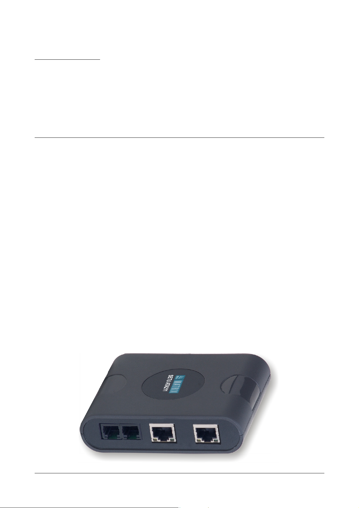
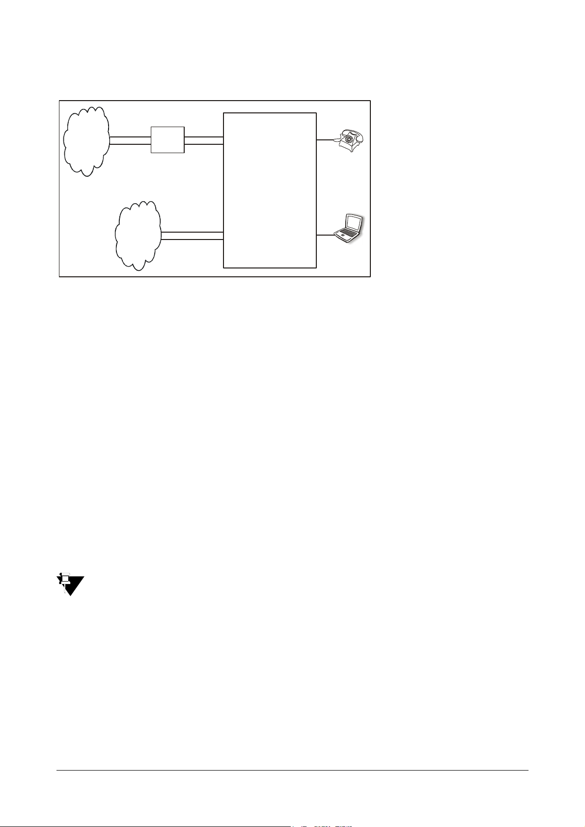
ATA211 is a VoIP Analog Telephone Adapter used as a SIP-FXS-FXO Gateway. It allows you to make and receive
voice calls over IP Network as well as PSTN network using conventional telephone instrument.
ATA211 uses SIP (Session Initiation Protocol) protocol to make voice calls over the IP network. ATA211 converts
the voice traffic into IP packets for transmission over the internet. When a telephone number is dialed by you,
ATA211 converts it into an IP call using the Session Initiation Protocol (SIP) and initiates a call, thereby making
VoIP calls as easy as normal telephone call. You have flexibility to make a call by selecting any SIP account or you
can also select FXO port to make a call.
The number dialed from FXS port can be routed to FXO port or SIP account based on the number dialed.
The Incoming call on SIP can be routed to FXS or FXO port or to a fixed destination number based on the CLI
received.
The Incoming call on the FXO port can be routed to FXS port or SIP account as programmed in Dialed Number
Table.
ATA211 can be used in Residence, SOHO, Corporate Offices, Industries, Workshops, etc. ATA211 can be used to
make voice calls to remotely located branch offices of an enterprise using Internet network.
ATA211 also offers flexibility to make VoIP calls over the Internet and browse the Internet simultaneously using
inbuilt router.
ATA211 has 1 WAN port, 1 LAN port, 1 FXS port, 1 FXO port, a Power Socket and 5 LEDs.
Matrix SETU ATA211 V1 System Manual 5
Page 12
WAN Port
The WAN port labeled as WAN is used to connect the ATA211 to Internet Network or to the LAN Network. Refer
topic “Applications of SETU ATA211” for more details.
LAN Port
The LAN port labeled as LAN is used to connect a PC to the ATA211. LAN port can also be connected to LAN
switch in certain applications. Refer topic “Applications of SETU ATA211” for more details.
FXS Port
The FXS port labeled as FXS is used to connect telephone instrument to the ATA211.
FXO Port
The FXO Port labeled as FXO is used to connect the ATA211 to the PSTN Network.
Power Socket
A Power Socket labeled as 12V DC is used to power the system using 12VDC, 1.25A power adaptor.
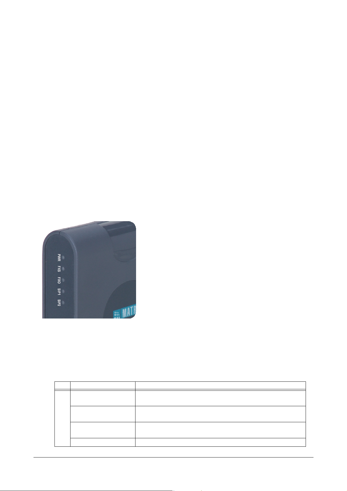
LEDs
The LEDs on the module are as shown in the figure below.
1. ATA211 has five LEDs namely FXS, FXO, SIP1, SIP2 and POWER. LEDs indicate the status of the ports,
various events occurring on the ports and also the error conditions.
2. The reset sequence: At Power ON, POWER LED will glow Green, continuously whereas all other LEDs
(FXS, FXO, SIP1 and SIP2) will glow Red for 3 times (250 ms On-time and 250 ms Off-time).
3. On successful completion of initialization cycle, each LED will glow as per the call conditions as described
below:
LED Status Meaning
FXS Continuously ON Indicates that FXS port is either OFF-hook or in speech during IC
Call/OG Call.
Blinks fast 200ms ON,
200ms OFF
Blinks slow 500ms ON,
500ms OFF
Continuously OFF Indicates that FXS port is in ON-Hook.
6 Matrix SETU ATA211 V1 System Manual
Indicates that FXS port is in Error state during IC/OG call.
Indicates that FXS port is Ringing for IC Call or Number is being
dialed for OG call (After end of dialing).
Page 13

LED Status Meaning
FXO Continuously ON Indicates that FXO port is either OFF-hook or in speech during IC
Call/OG Call.
Blinks fast 200ms ON,
Indicates that FXO port is in Error state during IC/OG call.
200ms OFF
Blinks slow 500ms ON,
500ms OFF
Indicates that FXO port is Ringing for IC Call or Number is being
dialed for OG call (After end of dialing).
Continuously OFF Indicates that FXO port is ON-hook.
SIP1 Continuously ON Indicates that SIP1 is enabled and is registered with the SIP server
or 'Active' status of SIP Account.
Blinks fast 200ms ON,
200ms OFF
Blinks slow 500ms ON,
500ms OFF
Indicates that SIP1 is enabled but not registered with the SIP server
(SIP is configured as proxy).
Indicates that SIP1 is enabled but not registered with the SIP server
(SIP is configured for P2P calling).
Continuously OFF Indicates that SIP1 is disabled.
SIP2 Continuously ON Indicates that SIP2 is enabled and is registered with the SIP server
or 'Active' status of SIP Account.
Blinks fast 200ms ON,
200ms OFF
Blinks slow 500ms ON,
500ms OFF
Indicates that SIP2 is enabled but not registered with the SIP server
(SIP is configured as proxy).
Indicates that SIP2 is enabled but not registered with the SIP server
(SIP is configured for P2P calling).
Continuously OFF Indicates that SIP2 is disabled.
SIP3 - (Refer Remarks)
Remarks:
1. The gateway supports that all the three SIP Accounts can be used for Peer to Peer calling OR can be used
for Proxy Calling. It also supports to use two SIP Accounts for Proxy calling and to use third SIP Account
for Peer to Peer calling.
2. User can know the registration status of SIP Account1 and SIP Account2 on LED. But, if user is using SIP
Account3 also for proxy calling, registration status for SIP Account3 can only be known from the 'Status
page' of Web Jeeves or issuing command from SLT. Refer appendices “System Commands” for display of
status using command.
Matrix SETU ATA211 V1 System Manual 7
Page 14

Programming Options
• SETU ATA211 gives flexibility to configure its parameters either using Conventional Phone Instrument or
computer. ATA211 supports embedded Web server (http based) so that the parameters can be configured
using GUI based special software called Web Jeeves.
• You will be able to configure only limited Parameters and features through phone. Please refer appendices
“System Commands”.
• Using computer, you can configure all the parameters of ATA211. To configure the parameters using
computer, configure the IP address and subnet mask of LAN/WAN port of ATA211 using phone and open
the Web Jeeves.
Configuring using Phone
You can configure the IP Address and Subnet Mask of LAN/WAN port and Connection Type of ATA211 using
Conventional Phone Instrument as explained below:
1. Pick up the handset of Analog Phone connected to ATA211.
2. Dial the programming access code #19 followed by the Admin Password (default is 1234). OR dial the
access code #18 followed by User Password (default is 1234). You will get programming tone.
3. To change the connection type of the WAN port, viz Static, DHCP or PPPoE, enter command:
15<Code>#*. To enable/disable 'L2 VLAN/CoS' on WAN port, enter command: 16<Code>#*. Where,
code is 0 for disable and 1 for enable.
4. Enter LAN IP address using the command: 12<LAN IP Address>#*. For example to enter IP address
192.168.1.120, enter the command 12<192168001120>#*.
5. Similarly enter Subnet mask of LAN port using command: 14-LAN Subnet Mask-#*.
6. Enter the WAN IP address using the command: 11-WAN IP Address-#* and enter WAN subnet mask
using the command: 13-WAN Subnet Mask-#*.
7. You can know the status of various network parameters on the display of your SLT. You can know the
connection type viz DHCP, PPPoE or Static, WAN IP address and subnet mask, LAN IP address and
subnet mask, Gateway address and DNS address.
8. Entering programming mode using command #18-1234 or #19-1234 and then enter the command 37-#*
to know the current connection type of ATA211. ATA211 will display the connection type on SLT display. If
the connection type is programmed as DHCP, you will get display for DHCP. Similarly you will get display
as PPPoE or Static as per type of connection.
9. Similarly, enter the command 31-#* to display the WAN IP address on SLT.
10. Enter the command 32-#* to display the LAN IP address on SLT.
11. Enter the command 33-#* to display the WAN subnet mask on SLT.
12. Enter the command 34-#* to display the LAN subnet mask on SLT.
13. Enter the command 35-#* to display the Gateway address on SLT.
8 Matrix SETU ATA211 V1 System Manual
Page 15
14. Enter the command 36-#* to display the DNS address on SLT.
FXS
LAN Port
FXO
15. Enter the command 38-SIP Account-#* to display the registration status of SIP account on SLT. For e.g.
The display will be '001' for 'Disable' status, when the SIP account is disabled.
The display will be '002' for 'Active' status, when SIP account is registered (for Proxy) or configured for
Peer-to-Peer.
The display will be '003' for 'Registering' status, when SIP account is in process of registration.
The display will be '004' for 'Failed' status, when any error condition occurs and no call can be made using
this SIP account.
16. Whenever you issue the command to display any parameter on the display of SLT, you need to go on-hook
after issuing the command. You will get ring and ATA211 will display the desired parameters for which
command is issued on SLT. You will again reach the programming mode on going off-hook.
17. When you issue valid command in programming mode, ATA211 plays confirmation tone for 3 seconds
followed by programming tone. To exit programming mode, enter '0'. You get dial tone if network
parameters are not changed or else the ATA211 will restart without dial tone/confirmation tone.
• When ATA211 gets IP from DHCP/PPPoE server, you can know these values by displaying it on FXS
port also. Refe appendices “System Commands” for other commands to display other parameters for
LAN and WAN port.
This is how LAN port and WAN port of ATA211 can be configured using Conventional Phone.
Configuring using Computer
To configure the IP Address and Subnet Mask of LAN/WAN port of ATA211 using Web Jeeves follow the steps
given below:
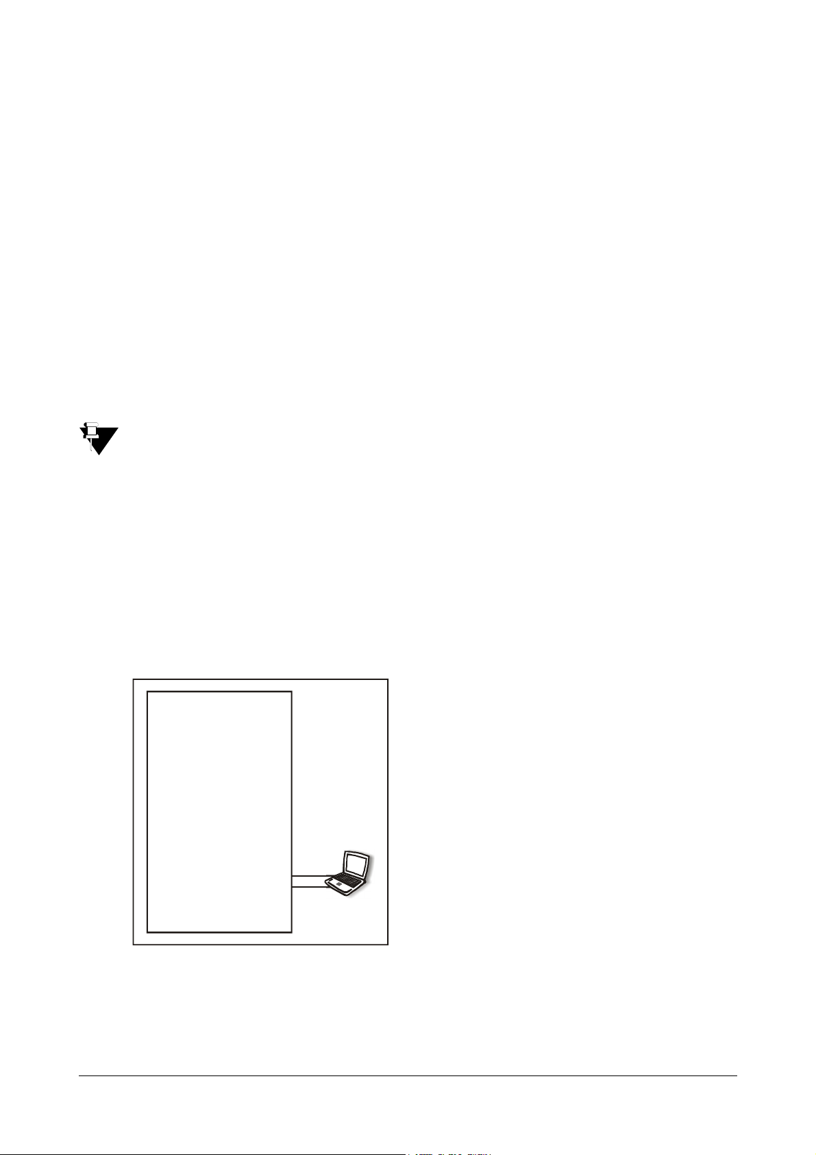
Changing the IP address of LAN/WAN port through LAN port:
1. Connect a computer to the LAN port of ATA211.
WAN Port
SETU ATA211
2. Know the IP Address and Subnet Mask of the computer by following the steps given below:
For Windows XP, Go to Control panel,
Right click on 'Local Area Connection'
Matrix SETU ATA211 V1 System Manual 9
Select Network Connections Network connections
Properties TCP/IP Connection Properties.
Page 16
If you are using Operating System other than Windows XP, contact your LAN administrator to determine
the IP address of the computer.
3. Change IP address and Subnet Mask of computer such that computer and LAN port of ATA211 are in
same subnet.
If you cannot change the IP address and subnet mask of your computer, please refer “Programming
Options” topic to change IP address and subnet mask of the LAN port of ATA211 using the phone
commands
12<LAN IP Address>#* and 14-LAN Subnet Mask-#*.
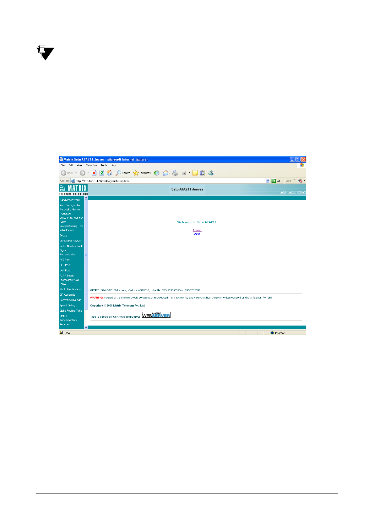
4. Open Web Jeeves of ATA211 by entering the programmed or default LAN port address in the URL field
and press 'Enter'. Default IP address of LAN port of ATA211 is 192.168.002.006 and default subnet mask
is 255.255.255.0.
5. Login into the Home page using the Admin password (default 1234).
6. Go to 'WAN port Parameter' link and change the required parameters there. If the IP Address is changed,
system will restart and you will have to login again !
7. If required, change the parameters of 'LAN port' also.
8. Please note that LAN port and WAN port of ATA211 must be in the different subnet else routing
functionality of ATA211 shall get affected.
9. Click on 'Submit'. The system shall reboot and user will be required to log in again using the new IP
Address.
10. Once the necessary changes are made it is advisable to restore the earlier settings of the computer while
removing the computer.
10 Matrix SETU ATA211 V1 System Manual
Page 17
Changing the IP address of LAN/WAN port through WAN port:
WAN Port FXS
LAN Port
FXO
1. Connect a computer to the WAN port of ATA211.
SETU ATA211
2. Know the IP Address and Subnet Mask of the computer by following the steps given below:
For Windows XP, Go to Control panel,
Right click on 'Local Area Connection'
Select Network Connections Network connections
Properties TCP/IP Connection Properties.
If you are using Operating System other than Windows XP, contact your LAN administrator to determine
the IP address of the computer.
3. Change IP address and Subnet Mask of the computer such that the WAN port of ATA211 and computer
connected to WAN port are in the same subnet.
If you cannot change the IP address and subnet mask of your computer, please refer topic “Programming
Options” to change IP address and subnet mask of WAN port of ATA211, using phone.
4. Open Web Jeeves of ATA211 by entering the default or assigned WAN port address in the URL field and
press 'Enter'. Note: The default IP address of WAN port of ATA211 is 192.168.001.171 and default subnet
mask is 255.255.255.0.
5. Login into the Home page using Admin password (default 1234).
6. Go to 'LAN port' link and make the required changes (after changes are done on this page, the system will
restart).
7. If required, change the parameters of 'WAN port' also.
8. Please note that LAN port and WAN port of ATA211 must be in the different subnet else routing
functionality of ATA211 shall get affected.
9. Click on 'Submit'. The system shall reboot and user will be required to log in again using the new IP
Address.
10. Once the necessary changes are made it is advisable to restore the earlier settings of the computer.
Please refer “Configuring SETU ATA211” for configuration of other parameters such as SIP Accounts, FXS
port etc.
Matrix SETU ATA211 V1 System Manual 11
Page 18

Admin Password and User Password
Admin is a person who installs, configures and maintains the SETU ATA211. Admin can also be the User.
User is a person who uses the SETU ATA211.
You can login into the Web Jeeves either using Admin Password or User Password.
Admin Password
Login using Admin Password will allow you to access all the parameters of ATA211. Default Admin Password is
1234.
User Password
Login using User Password will allow you to access only the limited parameters of ATA211. Default User Password
is 1234.
User and Admin both can access the pages of Web Jeeves as mentioned in topic 'Reinstate the Default Settings'
for (refer chapter “Reinstate the Default Settings”). All remaining pages are accessible only by Admin.
12 Matrix SETU ATA211 V1 System Manual
Page 19
Applications of SETU ATA211
PSTN
IP Network
Proxy
Broadband
Modem/Router
FXO
PSTN
IP Network
FXO
Broadband
Modem/Router
ATA211
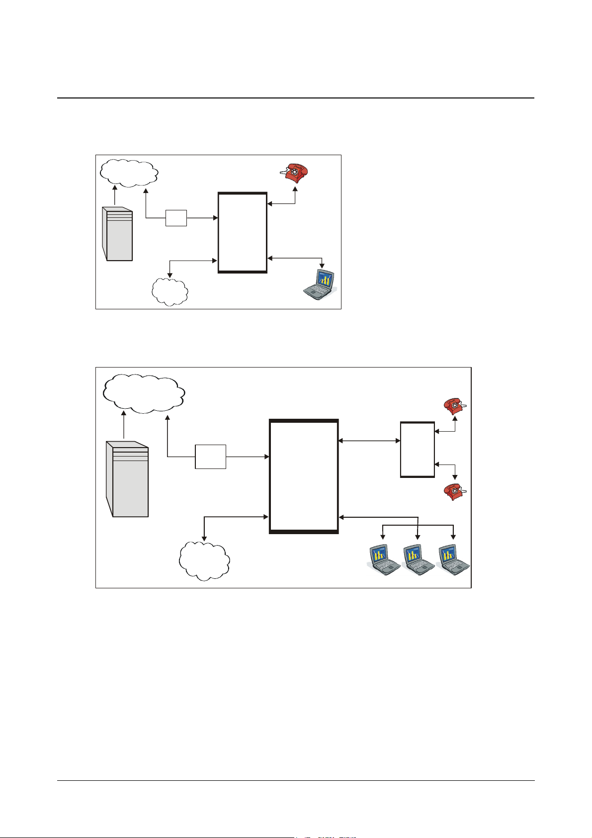
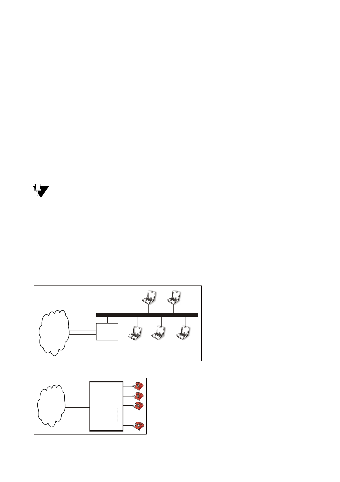
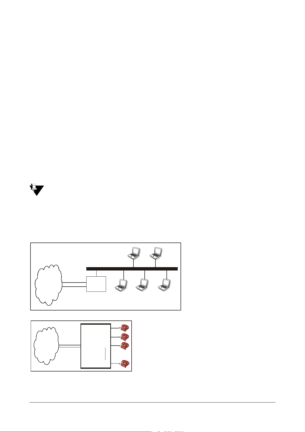
ATA211 finds its application in following scenarios:
1. Residential Application - Home users use ATA211 to make low-cost calls to their relatives staying
abroad.
FXS
ATA211
LAN
2. SOHO Application - Small Office owners use ATA211 to make low-cost calls to their overseas customers,
employees, suppliers, etc.
Proxy
WAN
FXS
PBX
LAN
Matrix SETU ATA211 V1 System Manual 13
Page 20
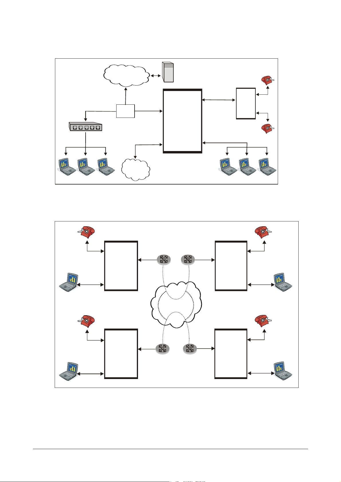
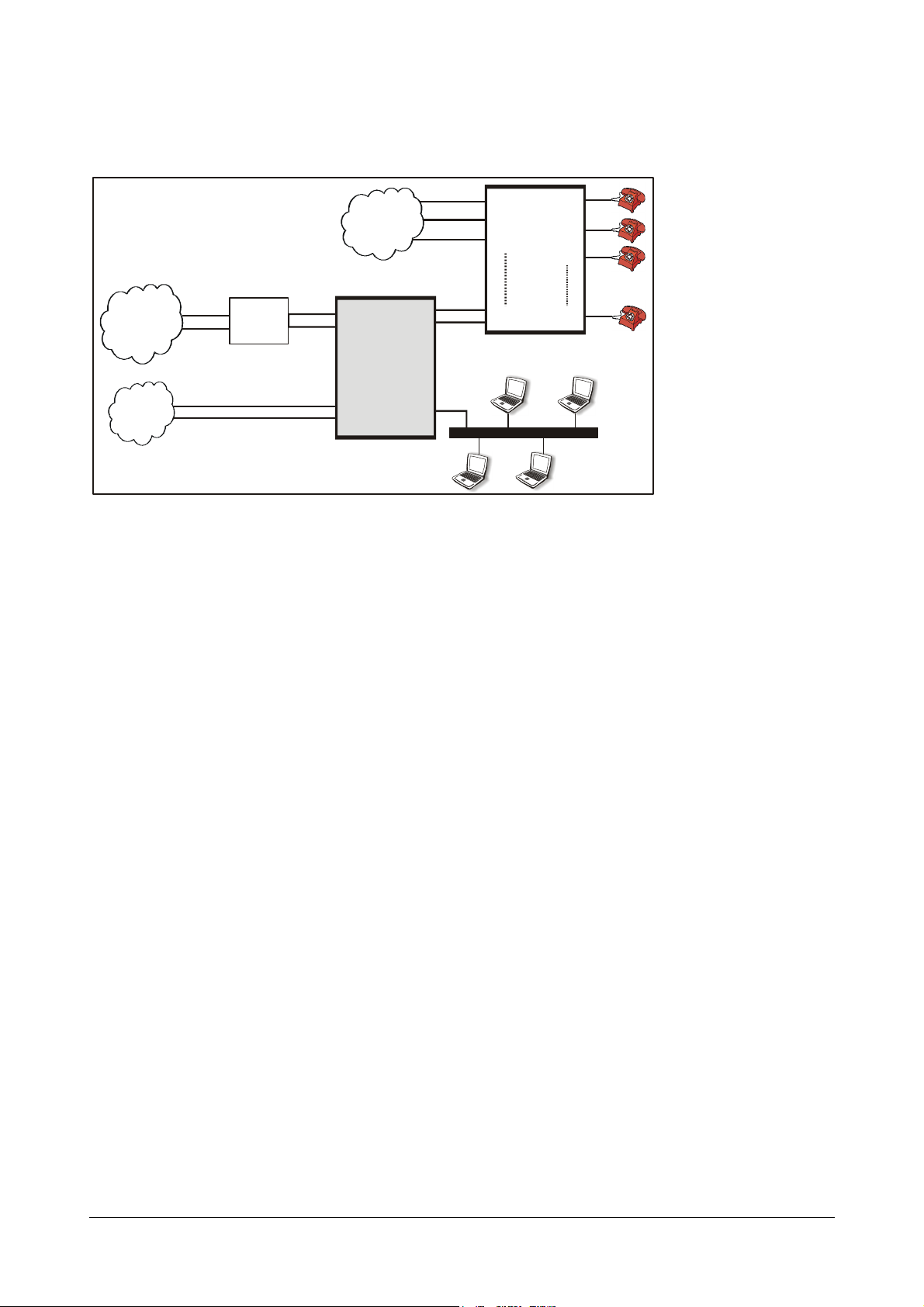
3. Business Application - Corporate Offices use ATA211 to make low-cost calls to their overseas
LAN
WAN
PSTN
IP Network
FXO
Switch
Proxy
Broadband
Modem/Router
ATA211
FXS
LAN
WAN
Broadband
Modem/Router
IP Network
FXS
LAN
WAN
ATA211
ATA211
Location D
Location C
Broadband
customers, employees, suppliers, etc.
FXS1
PBX
4. Peer-to-Peer Calls Application - Corporate Offices also use ATA211 to communicate between various
branch offices free of cost.
Modem/Router
Location A
FXS
WAN
ATA211
LAN
Location B
FXS
WAN
ATA211
LAN
Hope, now you know your SETU ATA211!
14 Matrix SETU ATA211 V1 System Manual
Page 21

CHAPTER 3
Getting Started
Protecting SETU ATA211
You should take following measures to protect your SETU ATA211.
Installation Precautions:
• Do not install the system in direct sunlight and the place where there is excessive cold or humid
atmosphere.
• Do not install the system where sulfuric gases are produced and in areas where there are thermal springs
because it may damage the equipment.
• Do not install the system at the places where shocks or vibrations are frequent or strong.
• Do not install the system at dusty places or places where it may come in direct contact with oil or water.
• The system should be installed at the place where enough open space is there for ventilation.
Safety Instructions:
You should always take basic safety precautions to reduce the risk of fire, electric shock and injury to the system as
well as the person using it. Follow the steps given below:
• Read and understand all the instructions given in the manual properly.
• Unplug the product from the wall outlet before cleaning and do not use liquid cleaners. Use only dry and
soft cloth.
• Do not use the product near water i.e. near a bath-tub, kitchen sink or near a swimming pool.
• Do not open the system in power ON condition.
• Do not place the product at the place from where it can fall and serious damage may be caused to the
product.
• Interfacing cables should not touch the exposed power line cable.
• The product should be operated with proper power voltage supply.
• Do not place the product where power cord can be misused.
• Do not overload wall outlets and extension cords as this can result in the risk of fire or electric shock.
• To reduce the risk of electric shock or damage to the system, take the product to the qualified serviceman
when some repair work or servicing is required. Removing covers or opening the system or incorrect
reassembly may cause electric shock when used subsequently.
Unplug the system from the wall outlet and contact the qualified service personnel under the following conditions:
• When the power supply cord or plug is damaged or frayed.
• If liquid has been spilled into the product.
• If the product has been exposed to rain or water.
Matrix SETU ATA211 V1 System Manual 15
Page 22

• If the product does not operate normally by following the operating instructions. Adjust only those controls
which are covered by the operating instructions because improper adjustment of other controls may result
in damage and will often require extensive work by a qualified technician to restore the product to normal
operation.
• If the product has been dropped or the cabinet has been damaged.
• If the product exhibits a distinct change in the performance.
16 Matrix SETU ATA211 V1 System Manual
Page 23
Installing SETU ATA211
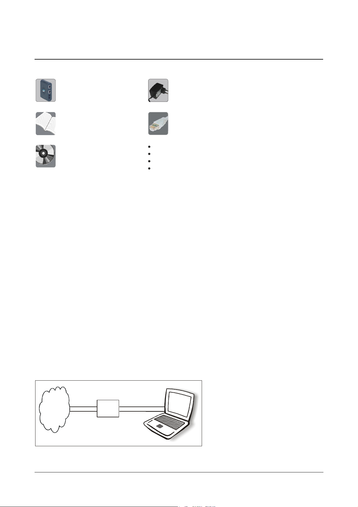
Two Screws M 7/30
SETU ATA211
(Country Specific)
CD containing System Manual,
Quick Start and User Card
Quick Start and User Card
IP
Broadband
Modem/Router
Computer
Before installing SETU ATA211, verify the package contents. The Sales Kit of SETU ATA211 contains:
Adaptor 12V, 1.25Amp
Ethernet Cable (RJ45)
Two Scr ew Grips
RJ11 Line Cord
Warranty Card Set
Make sure that all the above mentioned components are present when you open the Sales Kit of SETU ATA211. In
case any of the part is missing or damaged, contact the vendor/ITSP/system administrator from whom you have
purchased the system.
Mounting the ATA211 on wall
• Select a suitable place on the wall for mounting the ATA211.
• Drill a hole of appropriate size.
• Insert the nail grip in the hole.
• Insert the screw and tighten it leaving the screw head a few millimeters protruded of the wall.
• Check the strength of the nail.
• Hang the ATA211 on the wall.
ATA211 can be used for various applications as shown in the topic "Applications of SETU ATA211". ATA211 can be
installed in different scenarios as shown below.
Residential Application
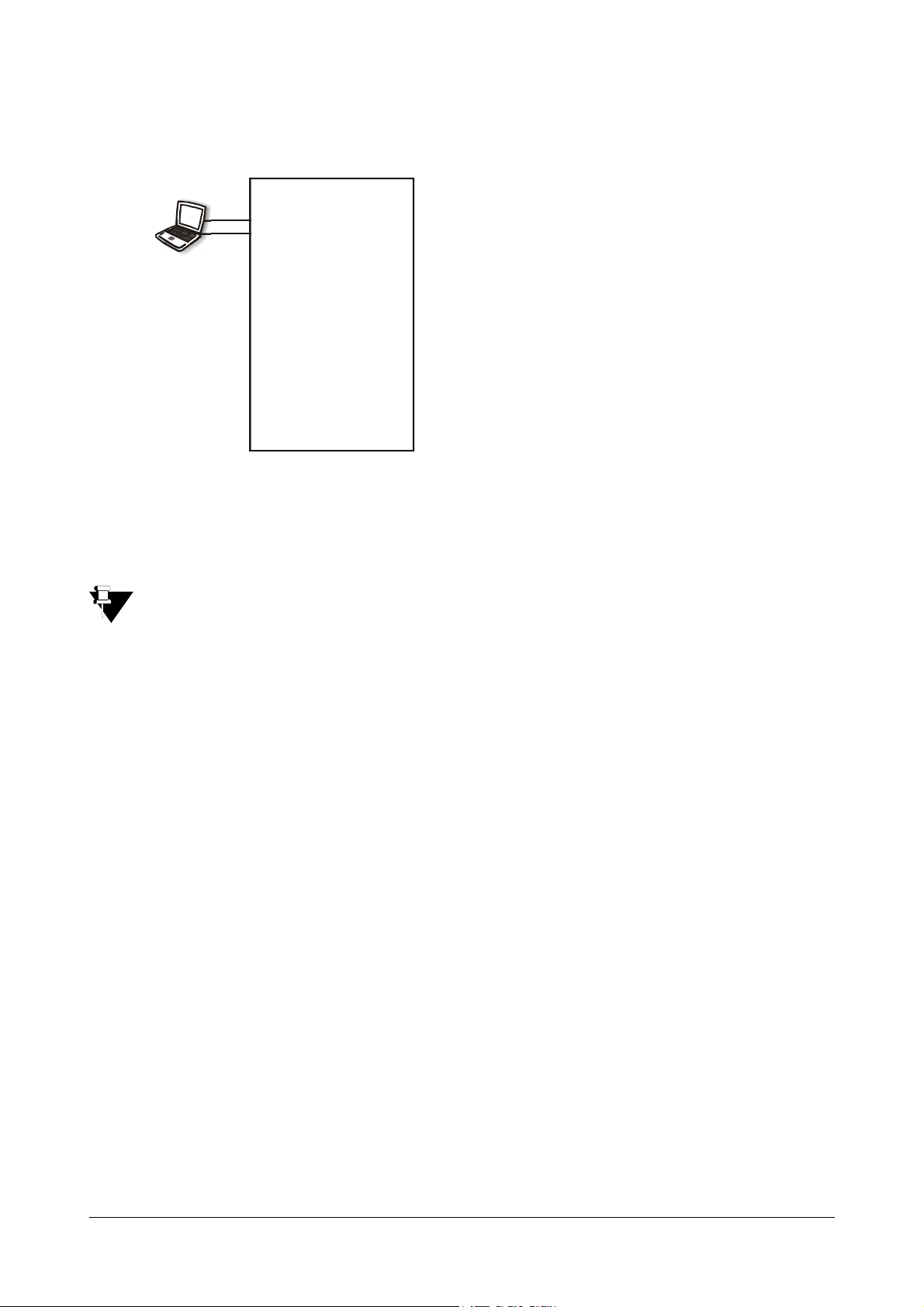
A typical home user has an Internet connection for surfing the net. He can purchase an ATA211 to make Voice calls
over the Internet.
The figure given below shows a typical connection made by the home user to surf the Internet before purchasing
ATA211.
Matrix SETU ATA211 V1 System Manual 17
Page 24
How to connect?
IP
POTS
WAN Port
FXS
LAN Port
FXO
Broadband
Modem/Router
After purchasing the ATA211, the home user should connect it as shown in the figure below:
SETU ATA211
1. Connect the WAN port of the ATA211 to the Ethernet (LAN) Port of the broadband modem/ router using a
straight Ethernet cable.
2. Connect telephone instruments to the FXS port using RJ11 cable.
3. Connect a PSTN line to the FXO port of ATA211.
4. Connect a computer to the LAN port of ATA211 using straight Ethernet cable.
5. Power the ATA211 by connecting the Power Adaptor to the Power jack.
6. At Power ON, the LEDs will glow as per the Table shown under the sub-topic LEDs in 'Knowing your SETU
ATA211'.
How to configure?
1. To access Jeeves using the computer connected to LAN port of ATA, ensure that the LAN port of ATA211
and the Computer are in the same subnet. The default IP address of the LAN port of ATA211 is
192.168.002.006 and the subnet mask is 255.255.255.0.
2. Change the IP address of the computer to 192.168.002.x where, x can be any number from 001 to 254
(except 006) and subnet mask of the computer to 255.255.255.0.
3. To know IP address of your computer (to change it if required), follow the steps below:
For Windows XP, Go to Control panel,
Connection'
Properties TCP/IP Connection Properties.
Select Network Connections Right click on 'Local Area
If you are using Operating System other than Windows XP, contact your LAN Administrator to determine
the IP address of the computer.
4. If it is not possible to change the IP address of the computer, change the IP address of the LAN port of
ATA211 using telephone instrument.
Please refer topic “Programming Options”.
5. Open Web Jeeves of ATA211 by entering the LAN IP address of the ATA211 in the URL field and press
'Enter'.
6. Login as 'Admin' into the Jeeves of ATA211 using the Admin password (default 1234). You will reach the
Home page.
18 Matrix SETU ATA211 V1 System Manual
Page 25
7. Click on 'WAN port' link and program parameters such as IP address, Subnet mask, Gateway address,
IP
Broadband
Modem/Router
PSTN
DNS address etc.ISPs generally use PPPoE or DHCP protocols to provide internet services. Enable
relevant option and configure its parameters. If your ISP provides Static IP address, then select "Enable
Static IP" option and configure the relevant parameters.
For more details, please refer topic “WAN Port” in Configuring SETU ATA211.
8. Click on the link 'SIP Accounts' and enter the values of parameters such as Registrar Settings,
Authentication, and Outbound Proxy etc. in the respective fields as provided by your ITSP.
For more details on programming SIP Account parameters, please refer topic “SIP Accounts” in
Configuring SETU ATA211.
9. Ensure that the SIP Account gets registered to the SIP server by checking the 'Status' page in Jeeves and
respective SIP LED on the product. (only for SIP1 or SIP2).
10. The set up is ready to make and receive VoIP calls. All incoming calls will land on your phone connected to
the FXS port and the calls will be made from SIP account SIP1.
• It is recommended to configure your broadband modem/router in 'Bridge Mode'. If doing so, configure
the IP address, Subnet Mask, Gateway Address and DNS address provided by your ISP in WAN port
of ATA211.
• To surf the internet using computer connected to LAN port of ATA, please program the IP address of
the LAN port of ATA211 as the 'Gateway Address' of the computer. Also, program the DNS address in
the computer as provided by the ISP.
SOHO Application
SOHO user purchases ATA211 to make calls to their customers, employees, suppliers etc staying abroad with
minimum cost. While making overseas calls they can also browse the Net simultaneously.
SOHO users generally have a typical set up in their offices as shown in the figure below:
FXS1
FXS2
PBX
FXS3
FXSn
FXO
Matrix SETU ATA211 V1 System Manual 19
Page 26
How to connect?
IP
WAN
ATA2 11
PBX
PSTN
FXO2
FXO1
FXO3
FXS1
FXS2
FXS3
FXSn
Broadband
Modem/Router
FXO
PSTN
After purchasing the ATA211, the SOHO users should connect ATA211 as shown in the figure below:
Figure 2:
FXS
FXOn
LAN
1. Connect the WAN port of the ATA211 to the Ethernet (LAN) Port of the broadband Modem/Router using a
straight Ethernet cable.
2. Connect LAN port of ATA211 to the Computers via Switch/Hub.
3. Connect FXS port of ATA211 to the FXO port of PBX using RJ11 cable.
4. Connect a PSTN line to the FXO port of ATA211.
5. Power the ATA211 by connecting the Power Adaptor to the Power jack.
6. At Power ON, the LEDs will glow as per the sub-topic LEDs in 'Knowing your SETU ATA211'.
How to Configure?
1. To access Jeeves using computer/s connected to LAN port of ATA, ensue that LAN port of ATA211 and the
2. Please note that the default IP address of the LAN port of ATA211 is 192.168.002.006 and the subnet
3. If net surfing is also to be done using the computers, please program the IP address of the LAN port of
4. Open Web Jeeves of ATA211 by entering the LAN IP address of the ATA211 in the URL field and press
computers in the LAN should be in the same subnet. Since the computers were already in a LAN network
before connecting ATA211, it would be inconvenient to change the IP address and subnet of all the
computers in the network. Hence, it would be better to change the IP address and subnet mask of the LAN
port of ATA211. This can be done using telephone instrument.
Please refer topic “Programming Options”.
mask is 255.255.255.0.
ATA211 as the 'Gateway Address' of the computer. Also, program the DNS address in the computer as
provided by the ISP.
'Enter'.
20 Matrix SETU ATA211 V1 System Manual
Page 27
5. Login as 'Admin' into the Jeeves of ATA211 using the Admin Password (default 1234). You will reach the
IP
Broadband
Modem/Router
PSTN
Home Page.
6. Click on 'WAN port' link and program parameters such as IP address, Subnet mask, Gateway address,
DNS address etc.ISPs generally use PPPoE or DHCP protocols to provide internet services. Enable
relevant option and configure its parameters. If your ISP provides Static IP address, then select "Enable
Static IP" option and configure the relevant parameters.
For more details, please refer topic “WAN Port” in Configuring SETU ATA211.
7. Click on the link 'SIP Accounts' and enter the values of parameters such as Registrar Settings,
Authentication, Outbound Proxy, etc. in the respective fields as provided by your ITSP.
For more details on programming SIP Account parameters, please refer topic “SIP Accounts” in
Configuring SETU ATA211.
8. Ensure that the SIP Account gets registered to the SIP server by checking the 'Status' page in the Jeeves
and respective SIP LED on the product (only for SIP1 and SIP2).
9. The set up is ready to make and receive VoIP calls. All incoming calls will land on your phone connected to
the FXS port and the calls will be made from SIP account SIP1.
It is recommended to configure your broadband modem/router in 'Bridge Mode'. If doing so, configure the
IP address, Subnet Mask, Gateway Address and DNS address provided by your ISP in WAN port of
ATA211.
Business Application (In corporate Office)
Corporate Offices use ATA211 to make low-cost calls to their overseas customers, employees, suppliers, etc.
In Offices, set-up before purchasing ATA211 is generally as shown in the figure below:
FXS1
FXS2
FXO
FXS3
FXSn
PBX
How to connect?
After purchasing the ATA211, Corporate users should connect ATA211 as shown in the figure below:
Matrix SETU ATA211 V1 System Manual 21
Page 28
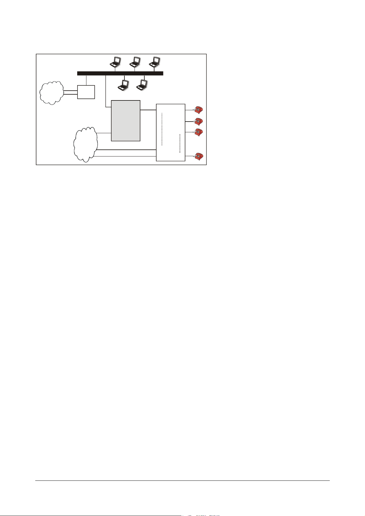
Figure 3:
IP
PSTN
ATA2 11
FXS
PBX
FXS1
FXS2
FXS3
FXSn
Broadband
Modem/Router
WAN
FXO
1. Connect WAN port of ATA211 to the LAN Switch/Network of the Enterprise.
2. Connect a PSTN line to the FXO port of ATA211.
3. Connect FXS port of ATA211 to the FXO port of PBX using RJ11 cable.
4. Power the ATA211 by connecting the Power Adaptor to the Power jack.
5. At power ON, the LEDs will glow as per the sub-topic LEDs in 'Knowing your SETU ATA211'.
LAN
FXO1
FXOn-1
FXOn
How to Configure?
1. To access Jeeves using computer connected to LAN switch, ensure that WAN port of ATA211 and the
computers in the LAN should be in the same subnet. Since the computers were already in a LAN network
before connecting ATA211, it would be inconvenient to change the IP address of all the computers in the
network. Hence, it would be better to change the IP address and subnet mask of the WAN port of ATA211.
This can be done using telephone instrument.
Please refer topic “Programming Options”.
2. Please note that the default IP address of the WAN port of ATA211 is 192.168.001.171 and the subnet
mask is 255.255.255.0.
3. Open Web Jeeves of ATA211 by entering the WAN IP address of the ATA211 in the URL field and press
Enter.
4. Login as 'Admin' into the Jeeves of ATA211 using the Admin password (default 1234). You will reach the
Home Page.
5. Click on 'WAN port' link and program parameters such as IP address, Subnet mask, Gateway address,
DNS address etc. Generally LAN administrators use DHCP or Static IP address with their network. Enable
relevant option and configure its parameters. Program the Broadband modem's or Router's LAN port IP
address as Gateway Address in the WAN port parameter page.
22 Matrix SETU ATA211 V1 System Manual
For more details, please refer topic “WAN Port” in Configuring SETU ATA211.
Page 29
6. Click on the link 'SIP Accounts' and enter the values of parameters such as Registrar Settings,
IP Network
Broadband
Modem/Router
Broadband
Modem/Router
WAN
ATA2 11
FXO1 FXS
FXO2
FXOn
FXS1
FXS2
FXS3
FXSn
PSTN
FXS
PBX
FXO
Authentication, Outbound Proxy, etc. in the respective fields as provided by your ITSP.
For more details on programming SIP Account Parameters, please refer topic “WAN Port” in Configuring
SETU ATA211.
7. Ensure that the SIP Account gets registered to the SIP server by checking the 'Status' page in the Jeeves
and respective SIP LED on the product (indication only for SIP1 or SIP2).
8. The set up is ready to make and receive VoIP calls. By default, all incoming calls will land on your phone
connected to the FXS port and the calls will be made from SIP account SIP1.
In this application LAN port of ATA211 can also be connected to a computer or to one of the port of another
LAN Network.
Peer-to-Peer Call Application
Corporate Offices can use ATA211 to communicate between their branch offices free of cost.
Residential Users can use ATA211 to communicate free of cost with their near and dear ones staying
geographically away from each other.
How to connect?
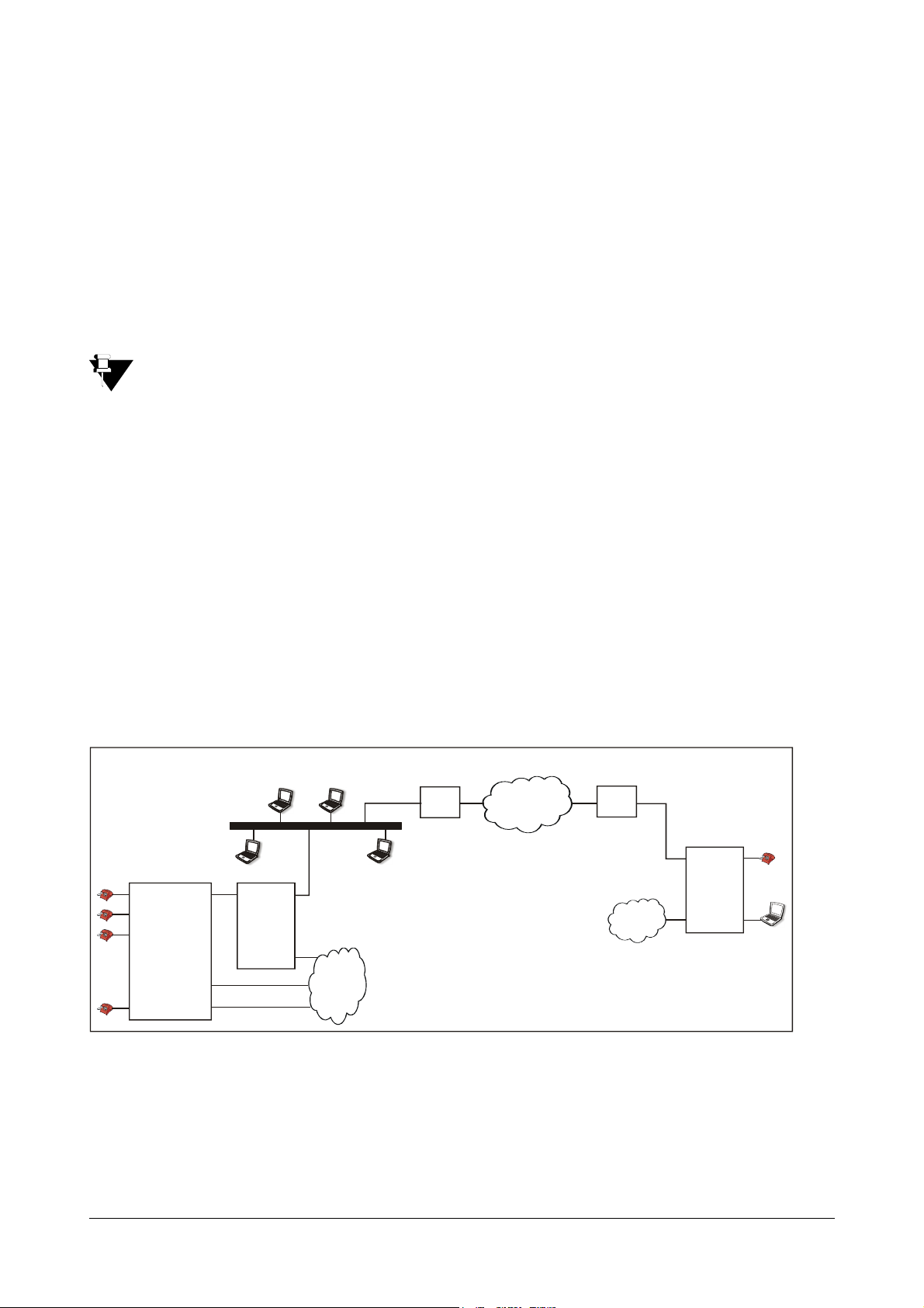
Corporate Users - Scenario1:
Suppose an organization has one branch office located overseas. The organization wants to establish a
mechanism whereby the calls between the branch office and head office become free. The organization can make
following set-up and configure the ATA211 as explained below.
Figure 4: Corporate Users-Scenario 1.
Head Office Branch Office
ATA2 11
WAN
LAN
PSTN
FXO
At Head office:
• Connect the WAN port of ATA211 to one of the ports of the LAN switch of the organization as shown in the
figure above.
• Connect the FXS port of the ATA211 to the FXO port of the PBX used by the organization.
• Connect the FXO port of ATA211 to a line from PSTN.
• Power the ATA211 by connecting the Power Adaptor to the Power jack.
Matrix SETU ATA211 V1 System Manual 23
Page 30
At Branch office:
IP Network
Broadband
Modem/Router
Broadband
Modem/Router
WAN
ATA211
FXO1 FXS
FXO2
FXOn
FXS1
FXSn
PSTN
PSTN
A
FXSWAN FXO1
FXO2
FXOn
FXS1
FXSn
Location A
PBX
199.57.74.92102.98.54.69
FXO
FXO
• Connect the WAN port of ATA211 directly to the Ethernet port of the Broadband modem/router.
• Connect the LAN port of ATA211 to the computer.
• Connect the telephone instrument to the FXS port of the ATA211.
• Connect the FXO port of ATA211 to a line from PSTN.
• Power the ATA211 by connecting the Power Adaptor to the Power jack.
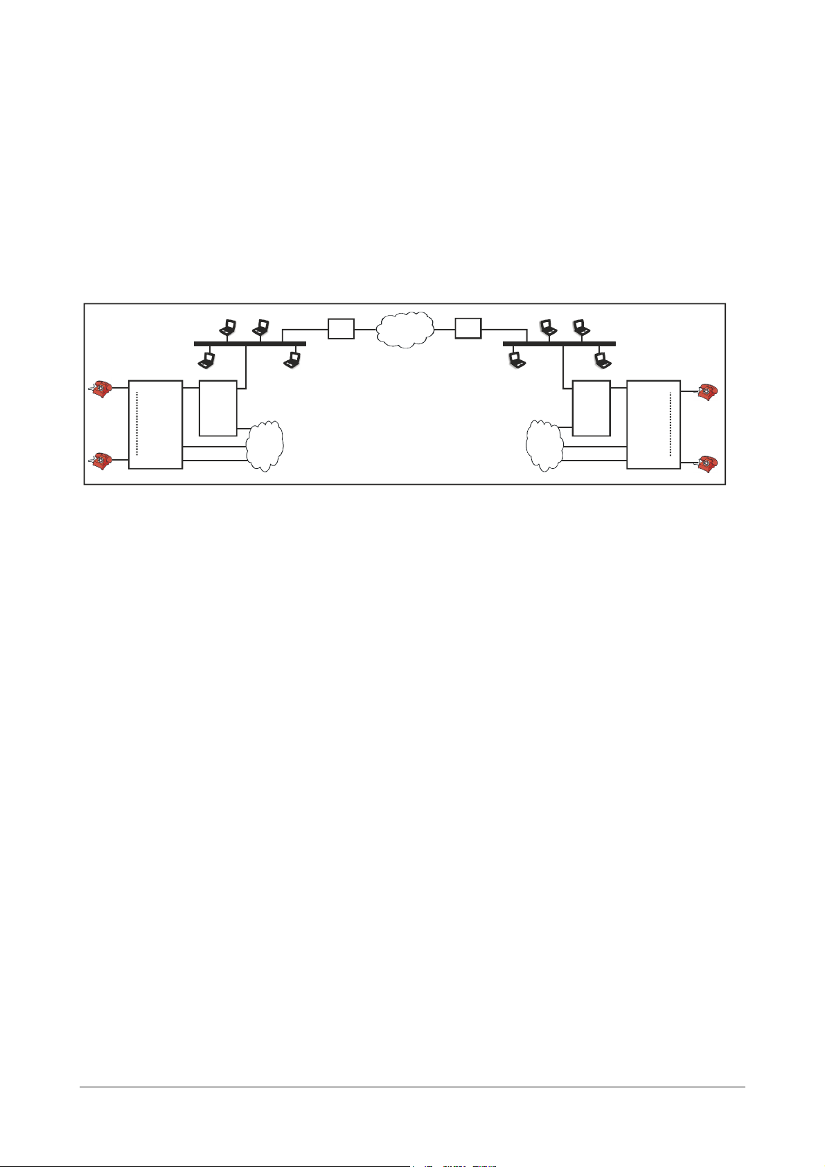
Corporate Users - Scenario2: (refer fig. 5 - when ATA211 is connected behind the
Broadband router NAT Type' other than symmetric' at both locations.)
Fig. 5: Corporate Users - Scenario 2.
Location B
TA211
192.168.1.1
192.168.1.2
At each location:
• Connect the WAN port of ATA211 to one of the ports of the LAN switch of the organization as shown in the
figure.
• Connect the FXS port of the ATA211 to the FXO port of the PBX used by the organization.
• Connect the FXO port of ATA211 to a line from PSTN.
• Power the ATA211 by connecting the Power Adaptor to the Power jack.
Corporate Users - Scenario3: (refer fig.5 - when ATA211 is connected behind the
Broadband router with NAT type 'Symmetric' at both the locations.)
At each location:
• Connect the WAN port of ATA211 to one of the ports of the LAN switch of the organization as shown in the
figure. The ATA211 is located behind the NAT.
• Connect the FXS port of the ATA211 to the FXO port of the PBX used by the organization.
• Connect the FXO port of ATA211 to a line from PSTN.
• Power the ATA211 by connecting the Power Adaptor to the Power jack.
Residential Users:
Suppose a family wants to talk frequently to their relatives staying overseas. They can use Peer-to-Peer application
of ATA211. They need to make following set-up and configure the ATA211 as explained below.
24 Matrix SETU ATA211 V1 System Manual
Page 31

Fig. 6: Residential Users:
WAN
ATA2 11
FXS
LAN
Broadband
Modem/Router
IP Network
Broadband
Modem/Router
ATA2 11
FXS
LAN
Location A Location B
PSTN PSTN
FXOFXO
WAN
At each location:
• Connect the WAN port of ATA211 directly to the Ethernet port of the Broadband modem/router.
• Connect the LAN port of ATA211 to the computer.
• Connect the telephone instrument to the FXS port of the ATA211.
• Connect the FXO port of ATA211 to a line from PSTN.
• Power the ATA211 by connecting the Power Adaptor to the Power jack.
How to configure?
Corporate Users - Scenario1:
Following steps should be done at the head office:
Configure the Broadband Router as follows:
• Forward SIP listening port (e.g., 5060) in Router to IP address of WAN port of ATA211 (for allowing
Incoming Call).
Configure the ATA211 as follows:
1. To access Jeeves using computers connected to LAN switch, ensure that the WAN port of ATA211 and the
computers in the LAN are in the same subnet. The default WAN IP address of ATAT211 is
192.168.001.171 and the subnet mask is 255.255.255.0.
2. Change the IP address and the subnet mask of the WAN port of ATA211 using telephone instrument.
Please refer topic “Programming Options”.
3. Open Web Jeeves of ATA211 by entering the WAN IP address of the ATA211 in the URL field and press
'Enter'.
4. Login as 'Admin' into the Jeeves of ATA211 using the Admin Password (default 1234). You will reach the
Home page.
5. Click on 'WAN Port' link and configure required parameters in the respective fields as mentioned below:
• Select 'Enable DHCP', if you want IP address, Subnet mask and Gateway address to be assigned by
DHCP server automatically.
• Select 'Enable Static IP', if you want to assign IP address, Subnet Mask and Gateway address
manually. Configure all the fields manually if you have selected this option.
Matrix SETU ATA211 V1 System Manual 25
Page 32

6. On the 'WAN Port' page, also keep the default parameter 'Use SIP port fetched using STUN?' as 'YES' (if
NAT type is 'other than symmetric) and program STUN server's address (the STUN server port is '3478',
by default) or program 'Use SIP port fetched using STUN? as 'NO' (if NAT type is 'Symmetric').
For more details, please refer topic “WAN Port” in Configuring SETU ATA211.
7. Click on 'SIP Accounts'. Configure the parameter 'Source Port IP Address' as 'Use IP Address fetch using
STUN'.
8. On 'SIP Account' program 'Enable SIP Account' for the SIP Account which is to be used. Program the
parameter 'SIP ID' for this SIP Account as '*'.
For more details on programming SIP Account parameters, please refer topic “SIP Accounts” in
Configuring SETU ATA211.
9. Click on 'Peer to Peer Call Table' link and program the number (say, 2001) assigned to the FXS port of the
ATA211 located at the branch office. Also program the IP address of broadband router/modem located at
the branch office. If you are comfortable dialing IP addresses directly after lifting the handset. Peer-to-Peer
table need not be programmed.
For more details, please refer topic “Peer-to-Peer Call Table” in Configuring SETU ATA211.
Following steps should be done at the branch office:
Configure the Broadband Router as follows:
• Configure the Router in Bridge mode.
Configure the ATA211:
1. Ensure that the LAN port of ATA211 and the computer connected to the LAN port are in the same subnet.
The default LAN IP address of ATAT211 is 192.168.002.006 and the subnet mask is 255.255.255.0.
2. Change the IP address of the computer to 192.168.002.x where, x can be any number from 001 to 254
(except 006). Also, change the subnet mask of the computer to 255.255.255.0.
Please refer topic “Programming Options”.
3. If it is not possible to change the IP address of the computer then change the IP address and the subnet
mask of the LAN port of ATA211 using telephone instrument.
Please refer topic “Programming Options”.
4. If net surfing is also to be done using the computer, please program the IP address of the LAN port of
ATA211 as the 'Gateway Address' of the computer. Also, program the DNS address in the computer as
provided by the ISP.
5. Open Web Jeeves of ATA211 by entering the LAN IP address of the ATA211 in the URL field and press
Enter.
6. Login as 'Admin' into the Jeeves of ATA211 using the Admin password (default 1234). You will reach the
Home page.
7. Click on 'WAN Port' link and configure required parameters in the respective fields as mentioned below:
• Select 'Enable DHCP', if you want IP address, Subnet mask and Gateway address to be assigned by
DHCP server automatically.
26 Matrix SETU ATA211 V1 System Manual
Page 33

• Select 'Enable Static IP', if you want to assign IP address, Subnet Mask and Gateway address
manually. Configure all the fields manually if you have selected this option.
For more details, please refer topic “WAN Port” in Configuring SETU ATA211.
8. Click on 'SIP Accounts' and on 'SIP Accounts' program 'Enable SIP Account' for the SIP Account which is
to be used and program the parameter 'SIP Id' for this SIP Account as '*'. Also program the parameter
'User Symmetric RTP?' as 'Yes' (for NAT type of Router at head office 'Symmetric')
For more details on programming SIP Account parameters, please refer topic “SIP Accounts” in
Configuring SETU ATA211.
9. Click on 'Peer to Peer Call Table' link and program following parameter:
a. Number field with the number (say, 3001) assigned to the FXS port of the ATA211 located at the head
office.
b. 'Destination Address' with the IP address of broadband router/modem located at the head office. if you
are comfortable dialing IP addresses directly after lifting the handset, Peer-to-Peer table need not be
programmed.
For more details, please refer topic “Peer-to-Peer Call Table” in Configuring SETU ATA211.
Corporate Users - Scenario2: (refer Fig. 5 - When ATA211 is connected behind the
Broadband router with NAT type 'Other than Symmetric' at both locations.)
Following steps should be done at both the locations:
Configure the Broadband Router at both locations as follows:
1. Forward SIP listening port (e.g., 5060 for both Routers) in Router to IP address of WAN port of ATA211
connected behind the respective router.
Configuring ATA211:
1. To access Jeeves using computers connected to WAN port of ATA, ensure that the WAN port of ATA211
and the computers in the LAN are in the same subnet. The default WAN IP address of ATA211 is
192.168.001.171 and the subnet mask is 255.255.255.0.
2. Change the IP address and the subnet mask of the WAN port of ATA211 (if required) using telephone
instrument.
Please refer topic “Programming Options”.
3. Program following parameters (for both locations):
• Open Web Jeeves of ATA211 by entering the WAN IP address of the ATA211 in the URL field and press
Enter.
• Login as 'Admin' into the Jeeves of ATA211 using the Admin password (default 1234). You will reach
the Home page.
• Click on 'WAN Port' link and enter the values of IP address, Subnet mask, Gateway and DNS address
in the respective fields.
• On the 'WAN Port' page, enable STUN by the parameter 'Use SIP port fetched using STUN?' (default
'YES'). Also program the STUN server address (By default STUN server port is '3478').
• Click on 'SIP Accounts' and program 'Enable SIP Account' for the SIP Account which is to be used.
Program the parameter 'SIP Id' for this SIP Account as '*' (for configuring it as P2P Account).
• On 'SIP Accounts' configure the parameter 'Source Port IP Address' as 'Use IP Address fetched using
STUN'.
4. Program following parameters (for Location A):
Matrix SETU ATA211 V1 System Manual 27
Page 34

• Click on 'Peer to Peer Call Table'. Program the number (say, 3001) assigned to the FXS port of the
ATA211 located at Location B.
• Program the IP Address of broadband modem/router located at the Location B.
• If the users are comfortable dialing IP addresses directly after lifting the handset, peer-to-peer table
need not be programmed.
5. Program following parameters (for Lcoation B)
• Click on 'Peer to Peer Call Table'. Program the number (say 2001) assigned to the FXS port of the
ATA211 located at Location A.
• Program the IP address of broadband modem/router located at the Location A.
• If the users are comfortable dialing IP addresses directly after lifting the handset, peer-to-peer table
need not be programmed.
Corporate Users - Scenario3: (refer Fig. 5 - When ATA211 is connected behind the
Broadband router with NAT type 'Symmetric' at both the locations.)
Following steps should be done at both the locations:
Configure the Broadband Router at both locations as follows:
1. Forward SIP listening port of client (e.g., 5060 for both Routers) in Router to IP address of WAN port of
ATA211 connected behind the respective router.
2. Forward RTP listening port in Router (to WAN IP address of ATA211 which is connected behind the
respective router).
Configuring ATA211:
1. To access Jeeves using computers to WAN port of ATA, ensure that the WAN port of ATA211 and the
computers in the LAN are in the same subnet. The default WAN IP address of ATA211 is 192.168.001.171
and the subnet mask is 255.255.255.0.
2. Change the IP address and the subnet mask of the WAN port of ATA211 (if required) using telephone
instrument.
Please refer topic “Programming Options”.
3. Program following parameters (for both locations):
• Open web Jeeves of ATA211 by entering the WAN IP address of the ATA211 in the URL field and press
Enter.
• Login as 'Admin' into the Jeeves of ATA211 using the Admin password (default 1234) you will reach the
Home page.
• Click on 'WAN Port' link and enter the values of IP address, Subnet mask, Gateway and DNS address
in the respective fields.
• On the 'WAN Port' page, also program the parameter 'Use SIP port fetched using STUN?' as 'No' (by
default it is 'YES').
• Click on 'SIP Accounts' and program 'Enable SIP Account' for the SIP Account which is to be used.
Program he parameter 'SIP Id' for this SIP Account as '*' (for configuring it as P2P Account).
• On 'SIP Account s', configure the parameter 'Use Symmetric RTP? as 'Yes' for the SIP Account to be
used.
4. Program following parameters (for Location A):
• Click on 'Peer to Peer Call Table'. Program the number (say, 3001) assigned to the FXS port of the
ATA211 located at Location B.
• If the users are comfortable dialing IP addresses directly after lifting the handset, peer-to-peer table
need not be programmed.
28 Matrix SETU ATA211 V1 System Manual
Page 35

5. Program following parameters (for Location B)
• Click on 'Peer to Peer Call Table'. Program the number (say, 2001) assigned to the FXS port of the
ATA211 located at Location A.
• If the user are comfortable dialing IP Addresses directly after lifting the handset, Peer-to-Peer table
need to be programmed.
Residential Users: (Refer fig. 6)
Following steps should be done at both the locations:
Configure the Broadband Routers at both the locations as follows:
Configure the Routers in Bridge mode.
Configuring ATA211:
1. Open Web Jeeves of ATA211 by entering the LAN IP address of the ATA211 in the URL field and press
'Enter'.
2. Login as 'Admin' into the Jeeves of ATA211 using the Admin password (default 1234).You will reach the
Home Page.
3. Click on 'WAN Port' link and configure required parameters in the respective fields as mentioned below:
• Select 'Enable DHCP', if you want IP address, Subnet mask, and Gateway address to be assigned by
DHCP server automatically.
• Select 'Enable PPPoE', if your ISP provides internet services using PPPoE. Configure Username,
Password and Service Name provided by your ISP, if you have selected this option.
• Select 'Enable Static IP', if you want to assign IP address, Subnet Mask and Gateway address
manually. Configure all the fields manually if you have selected this option.
For more details, please refer topic “WAN Port”.
4. On 'SIP Accounts' program 'Enable SIP Account' for the SIP Account, which is to be used. Program the
parameter 'SIP Id' for this SIP Account as '*' (for configuring it as P2P Account).
5. Program following parameters in ATA211 (for Location A):
• Click on 'Peer to Peer Call Table'. Program the number (say, 3001) assigned to the FXS port of the
ATA211 located at Location B, as Destination SIP-ID Number.
• Program the IP address of broadband modem/ router located at the Location B.
• If the users are comfortable dialing IP addresses directly after lifting the handset, Peer-to-Peer table
need not be programmed.
6. Program following parameters in ATA211 (for Location B):
• Click on 'Peer to Peer Call Table'. Program the number (say, 2001) assigned to the FXS port of the
ATA211 located at Location A, as Destination SIP-ID Number.
• Program the IP address of broadband modem/router located at the Location A.
• If the users are comfortable dialing IP addresses directly after lifting the handset, Peer-to-Peer table
need not be programmed.
If you are stuck somewhere while configuring you SETU ATA211, you may default the system as
mentioned in the topic '"Reinstate the Default Settings" and start configuration process again.
Matrix SETU ATA211 V1 System Manual 29
Page 36

Configuring ATA211 for Gateway functionality (Call Routing)
FXO to SIP routing:
• You can call to FXO port of ATA211 and dial the number. ATA will route this call using the SIP account
which is configured in ATA.
• To achieve this, ATA needs to be configured for the parameter 'Incoming call route' in the Web page 'FXO
Port'.
• Refer chapter “FXO Port” for the desired configuration.
FXO to desired port routing (dialed number based):
• You can also call to FXO port of ATA211 and dial the specific number. ATA will route the call to desired
destination route, based on the number dialed.
• To achieve this, ATA needs to be configured for the parameter 'Incoming call route' in the Web page 'Dialed
number Table'.
• Refer chapter “FXO Port” and “Dialed Number Table”.
FXO to fixed destination routing:
• You can call to FXO port of ATA211 and dial the number. ATA will route the call to the fixed destination
number, every time.
• To achieve this, ATA needs to be configured for the parameter 'Fixed Destination Number' in the Web page
'FXO Port'.
• Refer chapter “FXO Port”.
SIP to FXS or FXO routing:
• You can make call on the SIP account of ATA211and dial the number. ATA will route the call to destination
route; FXS or FXO depending upon the 'Number' for which the incoming call is received.
• To achieve this, ATA needs to be configured for desired Numbers and corresponding destination route in
the Web page Called Party Number Table.
• Refer chapter “Called Party Number Table”.
SIP to Fixed Destination Number:
• You can make call on the SIP account of ATA211and dial the number. ATA will route the Fixed Destination
Number.
• To achieve this, ATA needs to be configured for the option 'Route to fixed destination number through FXO'
and the desired number for the parameter 'Fixed Destination Number' in the web page 'SIP Accounts'.
• Refer chapter “SIP Accounts”.
Routing to FXO port using Auto PSTN Fall Back:
• If your SIP account does not get registered due to some reason, ATA can route the call through alternate
route of 'FXO Port'.
• To achieve this, ATA needs to be configured for 'Auto PSTN Fall Back' feature.
• Refer chapter “FXO Port”.
30 Matrix SETU ATA211 V1 System Manual
Page 37

Checking the Status
SETU ATA211 facilitates you to check whether you have installed it properly or not by displaying the status of all the
important parameters such as LAN Port, WAN Port, SIP Accounts and Auto Configuration on the Status page in the
Web Jeeves and also by indicating port status through LEDs. Refer sub-topic “LEDs” in Knowing SETU ATA211 to
check port status through LEDs.
You can also check Registration status of SIP Accounts on LCD display of the Phone connected to FXS
port by using the command. Refer appendices “System Commands”.
You can check the status of any of these parameters through Jeeves as mentioned below: Open the Web Jeeves of
SETU ATA211 and click on 'Status' link. (both Admin and User can access this Web page). The Web page will be as
shown below:
Matrix SETU ATA211 V1 System Manual 31
Page 38

Following is a brief description of the parameters displayed on the 'Status' page:
Parameter Description
System Name Displays the Name of System, configured in the 'System Parameter' page.
Version/Revision Displays the version & revision of the software, as VxRy. Where 'x' is the
version number and 'y' is the revision number of the current software.
Kernal Date Displays the date, when the current Kernel in the system was compiled. It will
be displayed in DD-MMM-YYYY format.( Refer Note1 below Table) e.g.
14-OCT-2009
32 Matrix SETU ATA211 V1 System Manual
Page 39

Parameter Description
LAN Port
IP Address Displays the IP address of LAN port currently used.
Subnet Mask Displays the subnet mask currently used.
MAC Address Displays the unique MAC address of LAN port.
WAN Port
IP Address Displays the IP address of WAN port currently used.
Subnet Mask Displays the subnet mask currently used.
Gateway Address Displays the gateway address currently used.
DNS Address Displays the domain name server address currently used.
DNS Domain Name Displays the DNS domain name currently used.
NTP Address Displays the NTP Server's Address currently used.
MAC Address Displays the MAC address of WAN port currently used either unique or cloned.
NAT Type Displays the type of NAT Type received in STUN response.
Router's Public IP Address. Displays the programmed router's public address.
IP Address fetched using STUN. Displays the IP address fetched using STUN.
SIP port fetched using STUN Displays the port fetched using STUN.
SIP Account1
Registration Status Displays the status for registration for the SIP Account, as Disable or
Registering or Active. (Refer Note2 below Table)
Registration Time Displays the registration time provided by server during registration.
Registration Retry Count Displays the number of attempts after failure, ATA sent registration request.
Reg. Last Failed Reason Display the messages about the reasons for registration last failed.
SIP Account2 Same as for SIP Account1.
SIP Account3 Same as for SIP Account1.
Auto Configuration
Status Displays the status after auto configuration is applied during power ON. e.g.,
"TFTP Server not found" "Auto Configured Successfully".
Statistics Displays the no. of files downloaded/configured as X/Y.
Note1:
The Kernal Date helps SE to know whether the Kernal is required to be compiled for new version, to support any
new feature (e.g. VLAN) in ATA211, so that he can ask the user to send the ATA211 to Factory, in case it is required
to be compiled.
Note2:
The status for registration as 'Active' will be displayed for following cases:
• When Proxy SIP Account is enabled, registered and 'Send REGISTER?' flag is set to 'Yes'
or
• When Proxy SIP Account is enabled, not registered and 'Send REGISTER?' flag is set to 'No'
or
• When P2P Account is enabled (irrespective of 'Send REGISTER?' flag).
Refer chapter “SIP Accounts” for more details of parameter 'Send REGISTER?'.
Now your SETU ATA211 is ready for use!
Matrix SETU ATA211 V1 System Manual 33
Page 40

34 Matrix SETU ATA211 V1 System Manual
Page 41

CHAPTER 4
Using SETU ATA211
Making Calls
SETU ATA211 is ready for making calls as soon as the initial configuration is done.
You can make the call by different ways using FXS port as mentioned below:
Making calls by dialing a number from FXS
Go OFF-Hook Dial the number Talk
Making calls using ATA211 is as easy as making a normal telephone call provided the entire necessary
configuration is done.
The calls made from FXS are routed as per 'Outgoing Call Route' selected viz. if. 'Outgoing Call Route' is selected
as SIP1, calls made from FXS are routed using SIP1. However, the desired SIP account, selected for 'Outgoing
Call Route' should be enabled (FXO port need not be enabled as it enabled, by default).
• The default settings can be changed by making necessary changes in "FXS Port" link in the Web
Jeeves. For more details, refer topic “FXS Port” in Configuring SETU ATA211.
• For dialing number from FXO/SIP and configure routing, refer chapters “SIP Accounts” or “FXO Port” in
configuring SETU ATA211.
Making calls by selecting the trunk
For dialing number from FXO:
Go OFF-Hook
For dialing number from SIP1:
Go OFF-Hook
For dialing number from SIP2:
Go OFF-Hook
For dialing number from SIP3:
Go OFF-Hook
Dial #83 Dial the number Talk
Dial #84 Dial the number Talk
Dial #85 Dial the number Talk
Dial #86 Dial the number Talk
Matrix SETU ATA211 V1 System Manual 35
Page 42

Using this feature you can make OG calls using specific trunk. You can select the required trunk (FXO/SIP1/SIP2/
SIP3) by dialing corresponding Access Code and then making call by dialing the number, irrespective of the port set
for 'Outgoing Call Route'.
Making Calls using Speed Dialing
Go OFF-Hook Dial #9-Index number Talk
You can dial the number by dialing access code i.e. #9 from FXS, followed by the Index number for that number
where it is configured in the speed dial table.
For more details on configuration of speed dialing, please refer sub-topic “Speed Dialing” in 'Configuring SETU
ATA211'.
Making Peer to Peer Calls
Go OFF-Hook Dial number stored in P2P table Talk
Peer to Peer calls are the calls made between two SIP clients without the intervention of a proxy server.
To make Peer to Peer call, you should configure peer to peer table in the Web Jeeves of ATA211. Also, you need to
enable the desired 'SIP Account', in web page 'SIP accounts', which is to be used as P2P trunk (or keep the
registrar server address for the SIP account, as blank).
Peer to Peer application is used by various branch offices of a corporate office and also by the residential user to
communicate with their relatives staying geographically away.
For more details, please refer “Peer-to-Peer Call Application” in 'Installing SETU ATA211' and "Peer to Peer Calls"
in 'Call Features'.
Direct IP Calling: You can make a call from FXS port by dialing 190*1*1*100 for making call to 190.1.1.100. (dot '.'
Should be dialed by using '*').
To avoid delay of Inter Digit Wait timer before the ATA dials the number, you can dial '#' at the end of
dialing digits for the number string while making calls.
36 Matrix SETU ATA211 V1 System Manual
Page 43

Receiving Calls
SETU ATA211 starts receiving calls as soon as it is switched ON after initial configuration.
Ring
Go OFF-Hook Talk
Once you have configured your ATA211 properly then receiving calls through ATA is as easy as receiving a normal
telephone call.
If you have configured all the SIP Accounts then the calls made to SIP1 or SIP2 or SIP3 or FXO will be placed on
FXS as per the default settings. You can also configure ATA211, to route the calls,made to SIP, to be placed on the
FXO port.
FXO or SIP: When you receive call on FXO or SIP, the number will be further routed to the port as per
settings of routing type. By default, call will be routed to FXS port and you will get 'ring' on the phone
connected to the FXS port. For changing routing type, refer chapters “SIP Accounts” or “FXO Port” in
Configuring SETU ATA211.
Matrix SETU ATA211 V1 System Manual 37
Page 44

Managing Calls
ATA211 gives you the facility of managing the calls by providing various Supplementary call services such as:
• Call Hold
• Call Transfer- Blind
• Call Transfer- Attended
• Call Toggle
• 3-Party Conference
• Making Second Call
• Call Waiting
• Making new call
• Disconnect the call
Call Hold
Call Hold feature allows you to hold the remote party. Maximum two calls can be put on Hold. Ensure that feature is
enabled in Class of Service. Refer “Class of Service” in chapter FXS Port.
How it works?
A is in speech with B
Hold a call
A dials Flash A gets feature tone. B goes on hold.
Retrieve Held Call
A dials Flash again within feature tone timer (7 seconds)
OR, A can dial 'Flash' within error state.
A goes on-hook A gets Ring
A goes off-hook A in speech with B
A in speech with B
You can hold the call only from FXS Port viz. only the calls made/received from/on FXS port can be held. You can
hold all type of calls made/received from/on FXS port viz. calls made to PSTN/SIP.
Call Hold feature will also be used with other features like Making Second Call, Call Waiting, Call Transfer- Blind,
Call Transfer-Attended, Call Toggle and 3-Party Conference.
Making Second Call
This feature helps you to make a second call by keeping the first call on 'Hold'. Ensure that 'Call Hold' feature is
enabled in Class of Service. Refer “Class of Service” in chapter FXS Port.
How it works?
A is in speech with B
A dials Flash B goes on hold. A gets feature tone.
A dials number of C A in speech with C
If you have made the first call on IP, it is possible to make following type of second call:
• PSTN Call
•IP Call
If you have made the first call on PSTN, it is possible to make only following type of second call:
•IP Call
38 Matrix SETU ATA211 V1 System Manual
Page 45

You can make maximum of two simultaneous calls.
Making second call feature is also used with other features such as Call Transfer-Attended, Call Toggle
and 3-Party Conference.
Call Transfer
Call Transfer helps the transferor to connect the transferee to the transfer target.
ATA211 will wait for the notification from the remote peer till expiry of 'Transfer Notification Timer'. The 'Transferor'
will be notified about Transfer Failure/ Error or Transfer Successful or Transfer Timeout (Default timer is 60
seconds). Transferor will get confirmation tone if call transfer is successful.
Call Transfer-Blind
Call transfer without consulting the party to whom call is to be transferred is called Blind Transfer. Ensure that
feature is enabled in Class of Service. Refer “Class of Service” in chapter FXS Port.
How it works?
A is in speech with B
A dials Flash-#6 B goes on hold. A gets dial tone.
A dials number of C B in speech with C
You can perform following types of transfer activity:
• You can transfer the PSTN call to the transfer target on IP.
• You can transfer the IP call to the transfer target on PSTN.
• You can transfer the IP call to the transfer target on IP.
Blind Transfer feature is applicable only from FXS port.
To know the call transfer results, 'A' should remain off-hook after dialing C's number.
• 'A' gets confirmation tone for 3 seconds followed by Dial tone if transfer is successful. 'A' gets error tone
followed by disconnecting the call, if call transfer is not successful.
Call Transfer-Attended
Call Transfer after consulting the party to whom the call is to be transferred is called Attended Transfer. Ensure that
feature is enabled in Class of Service. Refer “Class of Service” in chapter FXS Port.
How it works?
A is in speech with B
A dials Flash B goes on hold. A gets feature tone.
A dials number of C A in speech with C
A dials Flash-#7 B in speech with C
You can perform following types of transfer activity:
• You can transfer the PSTN call to the transfer target on IP.
• You can transfer the IP call to the transfer target on PSTN
• You can transfer the IP call to the transfer target on IP
Matrix SETU ATA211 V1 System Manual 39
Page 46

To know the call transfer results, 'A' should remain off-hook after dialing C's number.
• 'A' gets confirmation tone for 3 seconds followed by Dial tone if transfer is successful. 'A' gets error tone
followed by disconnecting the call, if call transfer is not successful.
Attended Transfer feature is applicable only from FXS Port.
Call Toggle
Call Toggle feature allows you to toggle between an active call and a held call without getting disconnected. Ensure
that feature is enabled in Class of Service. Refer “Class of Service” in chapter FXS Port.
How it works?
A in speech with B
A dials Flash B goes on hold. A gets feature tone
A dials number of C A in speech with C
A dials Flash-#4 A in speech with B. C goes on hold
A dials Flash-#4 again A in speech with C. B goes on hold
You can perform toggle activity for following types of calls:
• To toggle between two IP calls.
• To toggle between IP and PSTN call.
Call Toggle feature is applicable only for FXS Port.
3-Party Conference
3-Party Conference enables you to have conference between three parties. During conference all the three parties
can talk to each other. Ensure that feature is enabled in Class of Service. Refer “Class of Service” in chapter FXS
Port.
How it works?
A in speech with B
A dials Flash B goes on hold. A gets feature tone
A dials number of C A in speech with C
A dials Flash-#2 A in speech with B and C
A dials Flash-#4 A in speech with B. C goes on hold (3-PTY Conference converted to Call Toggle)
You can use Conference feature between two OG Calls or between two IC Calls or between One OG Call & One IC
Call.
Conference can be made between following types of users:
• If remote user1 is on PSTN and remote user2 is on IP OR
• If remote user1 is on IP and remote user2 is on PSTN OR
• If remote user1 is on IP and remote user2 is on IP
When you go on-hook during active Conference, the Conference will be terminated and both the calls will be
disconnected.
Conference feature is applicable only for FXS Port viz. Only FXS Port user can conduct Conference.
3-Party Conference can be converted to Call Toggle by dialing Call Toggle access code. User will be
connected to one of the parties and the other party goes on hold. While initiating the conference, the
ATA211 supports only G.711 (Mu-law) Vocoder.
40 Matrix SETU ATA211 V1 System Manual
Page 47

Call Waiting
This feature notifies you of another incoming call, when you are busy on a call. You will get beeps during speech
when you have waiting call. Ensure that feature is enabled in Class of Service. Refer “Class of Service” in chapter
'FXS Port'. For frequency and cadence of the Call Waiting Tone, refer CPTG in chapter “System Parameters”.
You have three options, when you are busy with the current call:
• You can reject the waiting call.
• You can hold the current call and attend the waiting call.
• You can disconnect the current call and attend the waiting call.
• If the feature is disabled, you will not get waiting beeps for the waiting call and the call gets rejected.
How it works?
A is in speech with B
C calls A A gets beeps while talking to B
Reject waiting call
A dials Flash-#3 Beeps stop. The call with C is rejected. A in speech with B
Hold current call and attend waiting call
A dials Flash-#4 B goes on Hold. A in speech with C
Disconnect current call and attend waiting call
A dials Flash-#5 B gets disconnected. A in speech with C
• You can attend/reject the call on IP when first call is on PSTN.
• You can attend/reject the call on IP when first call is on IP.
• You can attend/ignore the call on PSTN when fist call is on IP.
This feature is applicable only for FXS Port.
Using Web Jeeves
Open the Web Jeeves and click on 'Supplementary Services' link. (Both Admin and User can access this Web
page) The Web page will be shown below:
Call Waiting: Check the box to set/cancel the feature. By default, it is 'set'.
Matrix SETU ATA211 V1 System Manual 41
Page 48

Using Commands
• Enter programming mode by dialing #19-Admin Password or #18-User Password and then issue
following commands from the programming mode:
• To set/cancel Call Waiting, issue command 72-Code-#*, where Code=1 to set call waiting and code=0 to
cancel call waiting. By default it is ‘Set’.
Making new call
This feature enables you to make a call while you are in speech. When you dial the Access Code during an active
call, the ATA will release the current call and user will get the feature tone or dial tone. Now you can dial digits for
making new call.
Thus using this feature Access Code, it will be possible to disconnect the current call and restart dial tone only for
the calls made from FXS to FXO/SIP and FXO to FXS/SIP. The FXO port should not be busy while used for making
second call.
How it works?
A in speech with B
A dials #81 Current Call released. A gets dial tone/feature tone
A dials number of C A in speech with C
You can use access code for Making New Call, only on FXO and FXS port.
Refer topic “FXO Port” for more details.
Disconnect the call
Normally the call gets disconnected by the disconnect signal detection as supported by PSTN exchange or by the
specific message (Bye), received on SIP when remote user disconnects the call. But sometimes these signals are
failed and it is required to disconnect the call by another method. Using this feature, you can issue the specific
Access Code to release the current call.
How it works?
A in speech with B
A dials #82 Current Call released. A gets error tone
You can use access code for Disconnecting the Call, only on FXO and FXS ports. If the access code is used on
FXS or FXO port for the calls made from FXS/FXO to FXO or from FXS/FXO to SIP, the call will be released and
user will get error tone.
42 Matrix SETU ATA211 V1 System Manual
Page 49

Call Features
ATA211 supports various call features such as:
• Call Forward
• Caller ID
• DND
• Making call using Auto PSTN Fall Back
• Peer to Peer Calls
• Multi Stage Dialing through SIP and FXO
• Multiple Gateway Application
Call Forward
This feature enables you to forward calls to desired number when you are busy or not available at your place. You
can forward all incoming calls on SIP or FXO trunk only if the call is placed on your FXS port (routing type is
configured to route the call to FXS).
The ATA211 supports three call forward options:
• Call Forward-Unconditional
Use 'Call Forward-Unconditional' when you want to forward all incoming calls on SIP account or FXO.
• Call Forward-When Busy
Use 'Call Forward-Busy' when you want to forward the incoming calls on SIP account or FXO, when your
station is busy with other call or off-hook.
• Call Forward-When No Reply
Use 'Call Forward - When No Reply' when you want to forward the incoming calls on SIP account or FXO
after specified time. The call will be forwarded to the programmed destination, on expiry of the timer called
'Call Forward Timer'.
You can set different destination numbers for CF-Busy, CF-No Reply and CF-Unconditional. This feature
can be enabled/disabled through Web Jeeves as well as by issuing commands from FXS port.
Using Web Jeeves
Open the Web Jeeves and click on 'Supplementary Services' link.
Matrix SETU ATA211 V1 System Manual 43
Page 50

(Both Admin and User can access this Webpage). The Web page will be as shown below:
• To enable 'Call Forward' through Web Jeeves, select required Call forward option and enter the number or
IP address on which you want to forward the calls in the field for 'Destination Number'. By default all
options are disabled.
• The number can be of maximum 40 characters including ASCII characters. By default, it is blank.
• Also set the time after which call is to be forwarded to another number in "Call Forward Timer". The range
of Call Forward timer is 01 to 99. By default, it is 45 seconds. This timer is applicable only when Call
Forward- No Reply is selected. Refer chapter “Supplementary Services” in Configuring SETU ATA211.
Using Commands
Enter programming mode by dialing #19-Admin Password (default password 1234) or #18-User Password
(default password 1234) and then issue following commands from the Programming mode:
• To program Call Forward-Unconditional number, issue command 51-Destination number-#*.
• To set/cancel Call Forward-Unconditional, issue command 52-Code-#*, where Code=1 to set the feature
and Code=0 to cancel the feature.
• To program Call Forward-When Busy number, issue command 53-Destination number-#*.
• To set/cancel Call Forward-When Busy, issue command 54-Code-#*, where Code=1 to set the feature and
Code=0 to cancel the feature.
• To program Call Forward-When No Reply, issue command 55-Destination number-#*.
• To set/cancel Call Forward-When No Reply, issue command 56-Code-#*, where Code=1 to set the feature
and Code=0 to cancel the feature.
• To set Call Forward Ring Timer, issue command 57-Timer-#*, where Timer is time in seconds from 01-99.
Caller ID
Caller ID helps you to hide your identity from the called party by setting the value of Send Caller ID to NO. When
this feature is set to NO then the outgoing calls will be sent as Anonymous calls. By default, it is set as 'Yes' for all
SIP Accounts.
Please note that this feature is applicable only for SIP Calls.
44 Matrix SETU ATA211 V1 System Manual
Page 51

Caller ID feature can be enabled/disabled for the SIP Account, through Web Jeeves as well as by issuing
commands from FXS port.
Using Web Jeeves
Open the Web Jeeves and click on 'SIP Accounts' link. (Only Admin can access this Webpage). The Web page will
be as shown below:
To enable 'Caller ID' feature through Jeeves, set Send Caller ID = YES for the SIP Account.
Using Commands
Enter programming mode by dialing #19-Admin Password (default password 1234) and then issue following
commands from the Programming mode:
• To send/block Caller ID for SIP1,SIP2,SIP3 issue command 66-SIP Account-Code-#*, Where, SIP
Account is '1' for SIP Account1, '2' for SIP Account2 and '3' for SIP Account3. Code 1 is to Block and Code
0 is to Send the Caller ID.
DND (Do Not Disturb)
DND feature is useful when you do not want to receive any incoming calls. When DND feature is set on FXS port,
all IC calls on FXS port will be rejected by ATA211, but OG calls can be made as usual.
DND feature can be enabled/disabled through Web Jeeves as well as by issuing commands from FXS port. Ensure
that this feature is allowed from Class of Service in 'FXS Port' web page.
Matrix SETU ATA211 V1 System Manual 45
Page 52

Using Web Jeeves
Open the Web Jeeves and click 'Supplementary Services' link. (Both Admin and User can access this Webpage).
The Web page will be as shown below:
On above page, select 'Set/cancel' to enable/disable DND. Default is disable.
Using Commands
Enter programming mode by dialing #19-Admin Password (default password 1234) or #18-User Password
(default password 1234) and then issue following commands from the Programming mode:
• To set DND, issue command 61-Code-#*, where Code = 1 to set the feature and Code = 0 to cancel the
feature.
Making call using Auto PSTN Fall Back
During routing the PSTN/GSM number through SIP Account, it may happen that the Ethernet link is down or the
SIP account used is not registered. Hence the call will not be routed through SIP and you will get 'error tone'. To
avoid this, you can use the feature 'Auto PSTN Fallback' by which the call will be automatically routed from the
alternate port (FXO port).
Thus it is possible to route the SIP call to FXO port during following faulty conditions:
• SIP Account is enabled but not registered.
• SIP Account is configured for P2P calling but Ethernet link is down.
• SIP Account is registered but Ethernet link is down.
You will get an alert (beep) and then the call is routed from FXO port.
While routing the call to the FXO port, if FXO port is found busy, the system will wait for 45sec (FXO port
busy wait timer, which is programmable) for the port to become free. If FXO port becomes free within
45sec, the number will be out dialed on FXO port. Else the user will get error tone.
This feature is applicable for FXS port only.
46 Matrix SETU ATA211 V1 System Manual
Page 53

How to program?
Open the Web Jeeves and click on 'FXS Port' link. (Only Admin can access this Webpage). The Webpage will be
as shown below:
• Auto PSTN Fallback: Select Yes to enable the feature or No to disable the feature. Default is disable.
Special Features
ATA211 supports following special features:
• Peer to Peer Calls
• Multi Stage Dialing through SIP and FXO
• Multiple Gateway Application
Peer to Peer Calls
Calls made between two IP clients without the intervention of a Proxy Server are defined as Peer-to-Peer Calls
(P2P calls). P2P call can be made from FXS and FXO port.
Generally, Peer-to-Peer application is used for making intra-offices calls. Maximum of 500 offices can be interfaced
using ATA211. Each office should possess ATA211 with a static IP address. The FXS port of ATA can be connected
to the FXO port of the PBX at each branch office as shown in the figure. The Peer-to-Peer table should be
programmed at each location with the number which is to be dialed and destination IP address of the gateway at
other locations, to be called.
Matrix SETU ATA211 V1 System Manual 47
Page 54

Broadband Modem,
Mode m, etc.
Broadband Modem,
Modem , etc.
WAN
ATA 211
FXO1 FXSFXS1
FXS2
FXS3
FXSn
FXS1WAN FXO 1 FXS1
FXS2
FXS3
FXSn
PBX PBX
3001
4001
Broadband Modem,
Modem, etc.
Broadband Modem,
Modem, etc.
WAN
ATA 211
FXO1 FXSFXS1
FXS2
FXS3
FXSn
FXSWAN FXO1 FXS1
FXS2
FXS3
FXSn
PBX PBX
2001
5001
LAN
LAN
LAN
Location C
Location D
Location A
Location B
192.1.3.5 191.1.1.1
Cable Modem, DSL
Cable Modem, DSL
ATA211
IP Network
191.1.3.200 190.1.1.100
Cable Modem, DSL
Cable Modem, DSL
ATA211
LAN
How to program?
Open the Web Jeeves and click on the link 'Peer-to-Peer Call Table'. (Only Admin can access this Webpage). The
Webpage will be as shown below:
48 Matrix SETU ATA211 V1 System Manual
Page 55

• This screen shows a Peer-to-Peer table. By programming this table, the user gets away of dialing long and
uncomfortable IP address. This table serves as abbreviated dialing of IP numbers.
• Total 500 entries can be programmed in the Peer-to-Peer table. This implies 500 locations can be
connected.
• Each entry has following parameters viz. Name, Number and Destination Address. Refer chapter “Peer-to-
Peer Call Table” in Configuring SETU ATA211 for details about these parameters.
• With reference to the figure shown, following programming should be done in the Peer-to-Peer table of
ATA211 at Location-A.
Index Number Destination Address
001 300 190.1.1.100
002 400 191.1.3.200
003 500 192.1.3.5
• When the user 2001 dials 3001, a call is placed at IP address 190.1.1.100 since dialed number gets best
matched with the entry programmed at index 001. On receiving a call, the ATA211 at Location-B routes this
call to FXS port numbered as 3001.
• Making P2P call: For making 'Peer-to-Peer' call at all the locations, the SIP account (SIP1/SIP2/SIP3)
should be configured as P2P trunk. This can be done by entering SIP Id provided by ISP or configuring as
'*' for that trunk in the Web page 'SIP Accounts ' (by default '*' is programmed). You should also enable the
desired SIP Account.
• Receiving P2P call: To receive IC call on P2P trunk, at least one SIP account should be programmed with
'*' or SIP Id .The IC call will be routed to destination route FXS or FXO. Refer chapter “SIP Accounts” for
call routing options.
Refer topic “Making Calls” in this chapter 'Using SETU ATA211' for more information about making P2P
call.
Multi Stage Dialing through SIP and FXO
There are some applications where user needs to dial a fixed number string before dialing the actual number.
The ATA can be configured to take care for dialing the fixed number string every time when the actual number is
dialed through SIP account or FXO.
Matrix SETU ATA211 V1 System Manual 49
Page 56

For e.g. consider the following scenario: (In this figure, ATA is referred as ATA211)
FXS2
FXS1
PBX1
FXS3
FXS4
101
102
103
104
FXO3
FXO4
FXO2
FXO1
FXS1
PSTN
PSTN
FXS1
FXO3
FXO4
FXO2
FXO1
FXS2
FXS1
FXS3
FXS4
101
102
103
104
PBX2
101
102
103
104
FXS2
FXS1
PBX3
FXS3
FXS4
101
102
103
104
FXO3
FXO4
FXO2
FXO1
FXS1
IP PBX
IP
IP
21
ATA1
22
ATA2
24
ATA4
23
ATA3
IP
ATA1 - 21
ATA2 - 22
ATA3 - 23
ATA4 - 24
IP
FXO1
FXO2
FXO3
FXO4
PBX4
FXS1
FXS2
FXS3
FXS4
PSTN
FXS1
PSTN
• Customer has multiple offices across the globe which he wants to connect over IP network for voice
calling. But existing voice infrastructure which includes PCM/TDM PBX does not support VoIP connectivity.
To integrate VoIP functionality in existing voice infrastructure, customer installs ATA211 as shown in the
figure with existing PCM/TDM PBX.
• Customer has installed IPPBX on public IP network to which all ATA211 are registered. This is to take care
of NAT traversal and for easy maintenance.
• Now the voice communication over IP between the offices takes place as follows:
• If PBX1 extension 101 wants to connect to extension 102 of PBX2, caller first dials 22 (22 is the SIP-ID
assigned to ATA2 where caller wants to reach) with some trunk access code. The PBX1 routes this call
to its FXO port which is connected to the FXS port of ATA1.
• ATA1 then routes this call to IPPBX which is again routed by IPPBX to ATA2.
• ATA2 places the incoming call to its FXS port as per incoming call logic.
• When PBX2 receives the incoming call, Auto-Attendant or DID answers the call on its FXO port and
play dial message/dial tone. Caller then dials the desired called party number viz. 102. PBX places the
call to its extension viz. 102.
• To achieve the above calling methods between office sites, caller needs to dial the number in two stages
each time to reach the extension of other office. In first stage, caller first dials the SIP-ID of ATA which is
followed by the number of extension to be called in second stage.
• However, in the real scenarios, caller only wants to dial the complete number viz. SIP-ID of ATA and called
extension in one stage instead in two stages.
50 Matrix SETU ATA211 V1 System Manual
Page 57

• To avoid dialing the number in two stages by caller, the feature 'Multi Stage Dialing' is supported by ATA211
where caller only dials the complete number in one stage and ATA211 converts the dialing method in two
stages.
• When this feature is used, ATA211 (at calling end) will accept the complete number from caller and only
dial the number of remote SIP device which is also ATA211 (at called side). When call gets mature, ATA211
(at caller side) then sends the remaining number in DTMF to the called device.
• While ATA211 is sending the DTMF (actual destination number which is the extension of called PBX),
caller will hear the routing tone or silence depending on the 'Play Routing Tone' flag programmed in
'System Parameters' page.
• Customer should program following parameters for this feature: (refer 'How to program?' topic to know
which web page should be configured for these parameters)
• Program Dialed Number List and Substitute Number List
• Enable Automatic Number Translation (ANT) on desired SIP Account
• DTMF ON Time
• DTMF OFF Time
• Play Routing Tone flag
• Pause Timer
How to Program?
This feature can be configured by programming the web pages as explained below:
Open Web Jeeves of ATA211.
• Click on 'Automatic number Translation' link and program Dialed Number List and Substitute Number
List (Refer chapter “Automatic Number Translation” to program Dialed Number List and Substitute Number
List). The ATA211 will consider character '~' as Wait for Answer and character '^' as Pause when they are
programmed in the Substitute number List and will provide suitable delay.
Matrix SETU ATA211 V1 System Manual 51
Page 58

• Click on 'SIP Accounts' link and 'FXO Port' link to enable Automatic Number Translation (ANT). (Refer
chapter “SIP Accounts” and “FXO Port” to enable Automatic Number Translation (ANT)).
• Program Pause Timer (if required) (Refer chapter “SIP Accounts” to program Pause Timer for SIP and
refer chapter “FXO Port” to program Pause Timer for FXO)
• Program DTMF ON Time and DTMF OFF Time (only if required, most of the times you do not need to
change the default setting) (Refer chapter “SIP Accounts” to program DTMF ON Time and DTMF OFF
Time for SIP and refer chapter “FXO Port” to program DTMF ON Time and DTMF OFF Time for FXO)
52 Matrix SETU ATA211 V1 System Manual
Page 59

• Click on 'System Parameter' link and program 'Play Routing Tone?' flag as per your requirement.
• 'Play Routing Tone' flag will be applicable only when call is made from FXS to FXO port during MultiStage Dialing. (Refer chapter “System Parameters”to enable/disable playing routing tone)
• Routing Tone will be played only on FXS port when 'Play Routing Tone' flag is enabled. When caller is
calling using the SIP account, routing tone shall not be played (user will get silent) on SIP.
In the above scenario, if extensions of PBX1 want to reach the extensions of PBX2 by dialing 22 + Extension
Number (of PBX2), program the Dialed Number List-01 and Substitute Number List-02 (at calling side ATA
viz.ATA1) and as follows: (Refer web page for ANT)
Number List INDEX1 .. INDEX24
01 22
02 22~
03
:
08
• Ensure that 'Automatic Number Translation (ANT)' is enabled on SIP Account from where you want to
route the call.
• Keep 'DTMF ON and OFF Time' and 'Play Routing Tone?' parameters to default values if you don't have
any specific requirement.
• Now when any extension user of PBX1 dials '22 + Extension Number (of PBX2)' say 22101 (to reach the
extension 101 of PBX2),
• ATA1 will first dial out the ATA2 number viz. 22 and wait for answer. Caller will only hear routing tone.
DID/Auto-Attendant must be enabled on the FXO port of PBX at called side viz. PBX2.
• Once the call has been matured, ATA1 will send the remaining number viz. 101 in RFC 2833 (Outband)
to called device viz. ATA2.
• These DTMF digits are then detected by PBX2 on its FXO port and will place the call to extension 101.
• In the above scenario, if you want some delay after call gets mature and before ATA211 sends the
remaining DTMF digits, program '22~^' in Substitute Number List instead '22~' only.
• Similar programming is required to be done in each ATA211 connected at other sites.
Matrix SETU ATA211 V1 System Manual 53
Page 60

Multiple Gateway Application
Public
IP
A B
192.168.1 .0/24
ATA211
A
'Static routing table' helps you routing the call between point to point sites (connected through 'MPLS', Frame Relay
etc.) and to public internet at the same time. Refer chapter “Static Routing Table” for more details.
59.162.252.82
SIP Proxy
192.168.2.0/24
Frame Relay/MPLS
TA2 11
Generally, Static routing does not need to configure when ATA211 is connected behind the NAT router. LAN
interface of NAT router acts as default gateway for ATA211 and all calls initiated from ATA211 get routed from LAN
port of NAT router. But, if you have connected multiple offices through MPLS, Frame Relay etc and want to make/
receive Peer to Peer calls between various offices and Proxy calls to public internet at the same time, you need to
configure the Static Routing Table in ATA211.
As in the above figure, two offices are connected through MPLS or Frame Relay. User wants to make Peer to Peer
calls between two offices through Frame Relay/ MPLS network. At the same time, user also wants to make proxy
calls through public internet. Refer 'How to program?' topic below to know about the programming of such
configuration.
How to program?
Open the Web Jeeves and click on the link 'Static Routing Table'. (Only Admin can access this Webpage). The
Webpage will be as shown below:
• Total 5 entries can be programmed in Static Routing Table.
• Each entry has three parameters viz. Destination Address, Subnet Mask and Gateway Address.
54 Matrix SETU ATA211 V1 System Manual
Page 61

• Destination Address is the address of final destination where the call is to be made. This can be IP address
of called SIP device or network address where called SIP device resides.
• Subnet Mask is the mask to be applied on destination address.
• Gateway Address is the IP address of LAN interface of your router from where you want to route the call
for specific destination. This address must be in the same subnet where calling ATA211 resides.
By programming this table, ATA211 can route the calls on the basis of destination address. Calls for specified
network can be routed to specific gateway.
• With reference to the above figure, following programming should be done in the Static Routing Table of
ATA211 at location A.
Index Destination Address Subnet Mask Gateway Address
1 192.168.2.0 255.255.255.0 192.168.1.1
2
3
4
5
• Only one entry in Static Routing Table needs to be configured when only one gateway is required to be
called.
• Destination Address viz. 192.168.2.0 specifies the network address of location B.
• Subnet Mask specifies the mask to be applied on destination address.
• Gateway Address viz. 192.168.1.1 specifies the LAN address of router which is used to connect the ATA at
location A with ATA at location B.
• IP address of LAN interface of router which connect location A to public internet should be configured as
Default Gateway as in normal scenario. Refer chapter “WAN Port” for more details.
• Doing above programming, all calls made by ATA211 to 192.168.2.0/ 24 will be routed to router which
connects location A to location B. Whereas, all calls made by ATA211 to address other then 192.168.2.0/
24 will be routed to default gateway.
• Similar programming is required in ATA211 at location B to enable calling from location B to location A.
Hope, you know how to use SETU ATA211 now!
Matrix SETU ATA211 V1 System Manual 55
Page 62

56 Matrix SETU ATA211 V1 System Manual
Page 63

CHAPTER 5
In this chapter, you will learn the configuration of various parameters of ATA211.
Configuring SETU ATA211
Admin Password
Admin is a person who installs, configures and maintains the SETU ATA211. Logging into Jeeves using Admin
Password will allow you to access all the parameters of ATA211. Thus, the system allows you to change or modify
or default the Admin Password.
How to program?
Open the Web Jeeves and click on 'Admin Password' link. (Only Admin can access this Webpage). The Webpage
will be as shown below:
Change the Admin Password using Jeeves:
You can change Admin Password by following the steps given below:
• In 'Old Password' field enter the current password; enter new password in 'New Password' field and retype
new password in 'Retype To Confirm' field.
• Password can be of maximum 4 digits. Only digits 0-9 are allowed.
Whenever Admin changes the Admin Password from Jeeves, the Admin will be logout from the Jeeves as
a confirmation that in ATA211, the password has been changed.
Now, if you forget the password, you will be required to default the password. This can be done by
following:
• Default the Admin Password using Access Code.
Matrix SETU ATA211 V1 System Manual 57
Page 64

• Default the Admin Password using Jeeves.
Default the Admin Password using Access Code:
It is possible to default Admin password using access code. It can be done by following the steps given below:
• Dial the access code '#***'.
• You will get dial tone after successful execution of this Access Code.
• This will default the User Password to factory set value.
• Please note that this will default the Admin Password only if, the option 'Default Admin password when
User defaults the ATA?' is set to 'Yes' on Webpage 'System Parameter'. If the option for 'Default Admin
password when User defaults the ATA?' is set 'No', issuing command '#***' will not default the Admin
password. Refer chapter '“System Parameters”.
Default the Admin Password using Jeeves:
• If Admin wants to default the Admin password, using Jeeves, he can do so by clicking on the link for
'Default the ATA211'.
• Refer chapter “Reinstate the Default Settings”.
Relevant Topics:
1. “User Password” 133
2. “Reinstate the Default Settings” 145
3. “System Parameters” 123
58 Matrix SETU ATA211 V1 System Manual
Page 65

Auto Configuration
'Auto Configuration' feature of ATA211 enables the customer to configure ATA from a central location. This feature
has been designed to support ITSPs, who can store the configuration files of each ATA211 that they provide to their
customers on a TFTP server. When the ATA211 connects to the IP network, the ATA211 will automatically
download the configuration files stored on the TFTP server. The customer can thus start using the ATA without the
intervention or assistance of a technician.
How it Works?
ATA211 makes use of TFTP server to download the configuration files. User has to enter the Server Address
provided by ITSP and specify the Configuration Folder Path provided by ITSP in the Web page for 'Auto
Configuration'.
The 'Resync' feature will enable ATA to search for new configuration files periodically without the ATA being
restarted.
How to program?
Open the Web Jeeves and click on 'Auto Configuration' link. (Only Admin can access this Webpage). The Web
page will be as shown below.
Configure following parameters on the Web page:
Three options are provided for Auto Configuration:
• At Next Power ON: Select this option when you want that the ATA should be configured automatically only
during next power ON. This option is disabled, by default.
• At Power ON: Select this option when you want that the ATA should be configured automatically each time
it gets power ON. This option is disabled, by default.
• Never: Select this option when you do not want to configure the ATA automatically. This option is enabled,
by default.
TFTP Server Address
ATA supports programming of the TFTP server address manually or using the address provided by DHCP
server. If you are using DHCP server in your LAN and DHCP server provides the TFTP server address, do not
configure the TFTP server address manually; else Auto Configuration feature will not work.
Matrix SETU ATA211 V1 System Manual 59
Page 66

During power ON, if Auto Configuration is enabled but ATA does not get TFTP server address either from
DHCP server or address not programmed manually also, then the auto-configuration process is aborted and
the current configuration files are used by the ATA.
In this field of web page, enter the TFTP server address, if not provided by DHCP server. If DHCP server
provides TFTP server address, keep it blank. Maximum 40 characters are allowed. By default it is blank.
Config. Folder Path
When ATA gets auto configured at programmed time, ATA will send the request for the configuration files to
TFTP server and searches for the files in the configured folder by the name <ATA MAC Address>, where 'ATA
MAC Address' is the MAC address assigned to the WAN port of ATA. Hence, it should be taken care that the
'folder' in which files are stored in the TFTP server, should be named as the 'MAC address' corresponding to
the ATAs which are required to get configured automatically.
In this field of web page, enter the path of the folder provided by ITSP in which the configuration files are
stored. Maximum 96 characters are allowed. By default it is blank.
'Resync ATA' timer
Using this feature, the Admin need not restart ATA, manually for configuring ATA with new configuration files.
Resync feature will enable ATA to search for new configuration files periodically, without the ATA being
restarted, at the programmed time. The configuration files stored in the TFTP server will be retrieved. If any
new configuration file is found in the files received from TFTP server, all the configuration files will be loaded
and the ATA211 is restarted.
If no new configuration file is found in the files received from TFTP server, the auto configuration process is
discarded and currently stored files will be used.
To enable the feature, check the box for parameter 'Resync ATA at' in the web page 'Auto Configuration'.
Program the desired time for parameter, 'Resync ATA at' by configuring the Time in HH: MM format. Doing so,
ATA will 'resync' everyday at the time configured. HH = 00 to 23, MM = 00-59. By default = '00:00'.
If the parameter, 'Resync ATA at' is disabled (or the time for parameter ''Resync ATA at' is programmed as
00:00) the ATA will not resync. for new configuration files.
During 'Resync' if new configuration file is found and at that time if any of the port (FXS, SIP or FXO) is
not idle then ATA will not restart for Auto configuration.
Display on web page 'Status'
The user can know whether Auto-Configuration is successfully done or not and also the reason for failure, using the
'Status' page. For example, the status page will show following message:
• "Tftp Server not found"
• "Auto Configured Successfully"
In 'Statistics' field of 'Status' page, message will be displayed regarding how many files are downloaded
successfully out of total configuration files supported by ATA as X/Y, where X is the number of files downloaded
from TFTP Server and Y is the total number of configuration files supported by ATA. Refer chapter “Checking the
Status” in chapter 'Getting Started'.
60 Matrix SETU ATA211 V1 System Manual
Page 67

Relevant Topics:
1. “WAN Port” 134
2. “Checking the Status” 31
Matrix SETU ATA211 V1 System Manual 61
Page 68

Automatic Number Translation
• Automatic Number Translation (ANT) feature translates the number dialed by the user to the number that
is understood by the PSTN/ITSP (SIP) network.
• ANT is applicable on Destination Port (FXO or SIP1 or SIP2 or SIP3) only and when the call is made from
FXO or SIP (source port).
• Two number Lists are programmed for this feature: Dialed number list and Substitute number List.
• In the Dialed number list the numbers are programmed which are to be dialed by the user and in the
Substitute number List, the numbers are programmed which will be actually dialed out by ATA while out
dialing the number.
• You can program the Number List with the Number String which is to be dialed. You can program
maximum of 24 such number strings in one Number List, called 'Dialed Number List'. As per your
requirement, you can program different Dialed Number Lists ranging from 1 to 8. Assign this list number as
'Dialed Number List' in SIP or FXO port parameters for using ANT feature.
• You can program the Number List with the Number String which the ATA will dial out when the user dials
the number programmed in the corresponding Index of the Dialed Number List. You can program
maximum of 24 such number strings in one Number List called 'Substitute Number List'. As per your
requirement, you can program different Substitute Number Lists ranging from 1 to 8. Assign this list
number as 'Substitute Number List' in SIP or FXO port parameters for using ANT feature.
• You can program the special character for Pause timer in the number string configured in 'Substitute
Number List'. Refer “Pause Timer” in chapter 'FXO Port'. This will be used for ANT application like, multistage dialing. Refer chapter “Using SETU ATA211”.
Automatic Number Translation (ANT) on FXO is applicable when routing type for the call on SIP Account is
configured as 'Collect number and route to FXO'. Refer chapter “SIP Accounts”. It is not applicable for
source port as FXS port.
To elaborate:
While making international calls over IP, it is usually required to dial the same number as dialed when making
call using PSTN. E.g. User dials the number 001 479 29785434 on PSTN to make a call to U.S. User also
dials the same number when he wants to make call over IP as per the services provided by ITSP. But few
ITSP restrict user to dial only country code. This means, the user should only dial 1 479 29785434 to make a
call to U.S.
Now, since the user is habitual with dialing a complete number, he may dial the complete number with prefix
(00) and finally, this call will be rejected by ITSP. Hence using ANT feature, the user can manipulate the
number string as required by ITSP to complete the call. For above example, program the Dialed Number List1 and Substitute Number List-2, for ANT feature as shown below:
Number List Index1 Index2 .. Index24
1 001
21
:
8
Assign these List numbers to program the ANT feature in web page 'SIP Accounts' and enable 'ANT'.
Thus, '001 479 29785434' will be replaced by '1 479 29785434' when the number is dialed out by ATA. This is
called 'Automatic Number Translation' (ANT).
62 Matrix SETU ATA211 V1 System Manual
Page 69

How to Program?
Open the Web Jeeves and click on 'Automatic Number Translation' link. (Only Admin can access this Webpage).
The Web page will be as shown below:
You can program different Number lists from 1 to 8.
Index:
You can program maximum 24 number strings in each number list at the Index01, Index02….Index24,
respectively.
In the Number List, program the number strings of 24 characters maximum at different Index. ASCII
characters are allowed.
You can prepare different number lists as per your application. E.g. Allowed number list, Denied number list,
Dialed number list and Substitute number list.
The ATA211 will consider character '~' as Wait for Answer and character '^' as Pause when they are
programmed in the Substitute number List and will provide suitable delay before dialing next digit after this.
These characters are used for multi-stage dialing application. Refer chapter “Using SETU ATA211” for more
details.
By default all the Number List are Blank.
Refer chapter “SIP Accounts” for ANT on SIP Account and chapter “FXO Port” for ANT on FXO port.
Relevant Topics:
1. “SIP Accounts” 104
2. “FXO Port” 86
3. “Using SETU ATA211” 35
Matrix SETU ATA211 V1 System Manual 63
Page 70

Called Party Number Table
When there is an incoming call received on the SIP account, this call can be routed to FXS or FXO depending upon
the 'Number' for which the incoming call is received. This feature is called 'Called Party Number Based Routing'.
For this feature, the 'Called Party Number Table' is programmed in the system, using following parameters:
• Number
• Minimum Digit
• Maximum Digit
• Destination Route
In this Table, the specific 'Numbers' are programmed, for which the Incoming calls are to be received. When
the incoming call is received for any of these numbers, the call will be routed to the destination route
corresponding to the called number programmed in the Table.
Also, the destination route is specified in the first Index, which will be used by ATA for the numbers received,
which are not matching with the numbers programmed in the Called Number Table ('No Match Entry').
During incoming call, ATA may receive long number string which may not be required while out dialing the
'Number' after call routing. Hence, after receiving the call, to dial only the desired number of digits, from
destination port, ATA supports programming of 'Maximum number of digits' and 'Minimum number of digits' in
the Table.
Following points are relevant for configuring the Table:
If ATA will not wait for 'End of dialing digit' while out dialing the number, if the received the number of digits is equal
to or more than specified Maximum number of digits. (Default 'End of Dialing Digit' is '#' for the system).
If ATA has received the number of digits, less than 'Minimum number of digits' programmed in the Table, then the
caller who has made the call to ATA, will get error tone (because number will not be routed through ATA).
You can use this feature for following configurations of your ATA:
• FXS port of ATA211 is interfaced to the FXO port of PBX
• FXO port of ATA211 is interfaced to the FXS port of PBX
For example, to call the PSTN number through the ATA, the user can make call to ATA by dialing <022
24957434@WAN IP Address>. With suitable programming of Called Number Table, only the number 022
24957434 will be routed from FXO port of the ATA. Finally this call will be routed to FXS port of the PBX
which is connected to FXO port of ATA by suitable programming of the PBX for ANT and other features.
To use this feature the routing type for SIP account should be 'Route as per called party number'. Refer
chapter “SIP Accounts”.
How it works?
• When the ATA has received the called party number on the SIP Account, if the best match found in the
'Called Party Number Table' and minimum and maximum digits criteria is also satisfied with the entry
programmed in the table, the call will be routed as per the destination route programmed.
• If the received digits of called party number string is more than or equal to the programmed 'maximum
digits', ATA will consider it as end of dialing and call will be made through corresponding destination route.
• The received number is a valid number only if number of digits received is equal to or more than the
'minimum digits' programmed for that number prefix.
64 Matrix SETU ATA211 V1 System Manual
Page 71

'No Match Found':
• The 1st. entry is reserved for the received numbers which do not best match with any number programmed
in the table. For this, the destination route can be selected from options None/FXS/FXO. The option 'None'
is programmed, if ATA should not route the call for the number which is not programmed in the table. (the
received number call will be rejected).
Following is the Example for programming of the Called Number Table:
• Suppose called number table is programmed as shown below:
Index Number Minimum Digit Maximum Digit Destination Route
01 (No match found) 01 24 FXO
02 2 7 7 FXO
03 3 7 7 FXO
04 98 10 10 FXS
05 00 12 12 FXS
In this Table:
• The incoming call with the 'called number string' which is not programmed in Called Number Table, will
be routed from 'FXO' port programmed at Index01. (No match entry).
• The numbers which are to be received with prefix '2' (e.g. PSTN numbers) are programmed in Index02,
destination route is programmed as 'FXO' and Minimum digits to consider the number as valid number
is programmed as 7. Also the maximum number of digits is programmed as 7. Hence all numbers
received with 7 or more digits, starting from '2' will be routed to 'FXO'. For e.g. if the received number is
'2630555', it will be routed from 'FXO' port. (If the number string received during incoming call is
'2630555123', then ATA will dial out the number '2630555' only, as the maximum digits programmed is
'7').
• The numbers which are to be received with prefix '3' are programmed in Index03, destination route is
programmed as 'FXO' and Minimum digits to consider the number as valid number is programmed as
7. Also the maximum number of digits is programmed as 7. Hence all numbers with 7 or more digits,
starting from '3' will be routed from FXO. For e.g. if the received number is '3065571', it will be routed
from 'FXO' port.
• The numbers which are to be received with prefix '98' (e.g. Mobile numbers) are programmed in
Index04, destination route is programmed as 'FXS' and Minimum digits to consider the number as valid
number is programmed as 10. Also the maximum number of digits to consider as end of dialing is
programmed as 10. Hence all numbers with 10 or more digits, starting from '98' will be routed from
'FXS'. For e.g. if the received number is '9898074306', it will be routed from 'FXS' port.
• The numbers which are to be received with prefix '00' (e.g. ISD numbers) are programmed in Index05,
destination route is programmed as 'FXO' and Minimum digits to consider the number as valid number
is programmed as 12. Also the maximum number of digits is programmed as 12. Hence all numbers of
12 or more digits, starting from '00' will be routed from 'FXO'. For e.g. if the received number is ISD
number with prefix '00', it will be routed from 'FXS' port.
How to program?
Open the Web Jeeves and click on 'Called Party Number Table' link. (Only Admin can access this Webpage).
Matrix SETU ATA211 V1 System Manual 65
Page 72

The Webpage will be as shown below:
You can program maximum of 10 entries in the Table at different Index from 01 to 10.
• Number: Program numbers which will be received as the 'Called Number' at the Index 02 to 10, using
max.24 characters. ASCII Characters are allowed. 1st.entry, is for the case 'No Match Found' and number
can not be programmed in this field. Default = Blank for Index02 to Index10.
• Minimum Digit: Program number for Minimum digit for the valid number to be routed by ATA.
Range = 01-24, Default = 01 for all Index.
• Maximum Digit: Program number for Maximum digits for the Number to be routed by ATA.
Range = 01-24, Default = 24 for all Index.
• Destination Route: Select the route on which ATA should place a call when the programmed prefix
number is received during Incoming call.
• For Index01: You can select the option for the route, from: None/FXS/FXO. If 'None' is programmed
all the IC calls for No match number will be rejected. Default = FXS.
• For Index02 to Index10: You can select the option for the route from: FXS/FXO. Default = FXO.
Relevant Topics:
1. “SIP Accounts” 104
2. “Dialed Number Table” 74
66 Matrix SETU ATA211 V1 System Manual
Page 73

Daylight Savings Time Adjustments
• In many countries clocks are advanced at the beginning of the Daylight Saving Time (DST) and delayed at
the end of Day Light Saving Time. ATA211 supports to maintain the clock accordingly for such changes.
• Program the parameters as per the DST rules of the Country where the ATA211 is installed. Disable
Daylight Saving Adjustment if not applicable in the country.
• DST can be set according to Day-Month Wise or Date-Month Wise.
• DST is changed on a particular day and month every year for some countries. The DST is changed on
exact date and month every year for some other countries and some countries don't follow DST.
• If "Day-Month Wise' is selected, the DST is effective on the programmed day and the month whereas, if
'Date-Month Wise' is selected, the DST is effective on the programmed date and the month.
• The configuration of DST parameters is explained with Examples, after explaining the programming of
DST.
When ATA211 gets defaulted, DST parameters will not be set to default values.
How to program?
Open the Web Jeeves and click on 'Daylight Saving Time Adjustments' link. (Only Admin can access this
Webpage). The Web page will be as shown below:
Forward Time Adjustments:
• Type: Select the type from following options:
• None: Program this option for a country where DST is not applicable.
Matrix SETU ATA211 V1 System Manual 67
Page 74

• Day-Month wise: Program this option only for a country where DST is observed as per Day-Month
wise every year.
• Date-Month wise: Program this option only for a country where DST is observed as per Date-Month
wise every year.
Default = None.
Day-Month Wise:
• Program 'day' and 'month' on which DST will be applied every year. For this, program Ordinal, Day and
Month. For this option, 'Type' should be selected as 'Day-Month wise'. Default = 1st Sunday January.
• Ordinal: Program 1st, 2nd, 3rd, 4th, or 5th. For example if DST starts on first Sunday of January every
year, then program '1st' here.
When the DST of a particular country starts or ends on the Last Sunday or any other day e.g. the last
Tuesday, last Friday of the month, always set the Ordinal Number as '5th'.
• Day: Program the day on which DST starts. Select from: Sunday, Monday, Tuesday, Wednesday,
Thursday, Friday, Saturday
• Month: Program the month on which DST starts every year. Select the month from January to December
of the year.
• Change Time From: It is the current time settings at which DST will start to change. The time is in HH:MM
(Hours-Minutes) format, where HH=00 to 23 and MM=00 to 59. Default = 00:00.
• To: It is the time to which the DST is advanced. Enter the time in HH:MM (Hours-Minutes). Default =
00:00.
Date-Month wise:
• Program 'date' and 'month' on which DST will be applied every year. Default = 01January.
• Date: Program the date on which DST starts. Select from '01' to '31' of the month. For example if first
January is the DST date, then select '01'. Default = 01.
• Month: Program the month on which DST starts every year. Select the month from January to December.
Default = January.
• Change Time From: It is the current time settings at which DST will start to change. The time is in HH:MM
(Hours-Minutes) format. Default = 00:00.
• To: It is the time to which the DST is advanced. Enter the time in HH:MM (Hours-Minutes). Default =
00:00.
Backward Time Adjustments:
• Select this option 'Backward Time Adjustments' to set the time back (i.e. end DST and begin standard
time).
• Follow the same steps described above (for 'Forward Time Adjustments) to set the day/date, month, hours
and minutes except, here you must set these parameters according to the time when DST ends.
If for some country, the Backward or Forwarded Time Adjustments is at 00:00 hours, use previous date
with "from" time = 23:59 and "to" time as required.
The following are different examples for DST details, if you were installing SETU ATA211, in the European Union,
Chile and Israel:
Example 1:
If you are installing ATA211 in a country in the European Union, as per the European Summer Time, the DST would
start on the last Sunday in March and end on the last Sunday in October each year. Clocks are advanced by one
hour at 01:00 hours GMT at the start of DST and set back by one hour at 01:00 hours GMT when DST ends.
• Go to the option 'Forward Time Adjustments' to advance the time when DST starts.
68 Matrix SETU ATA211 V1 System Manual
Page 75

• Select 'Day-Month Wise' as the 'Type' of forward time adjustment
• Select '5th' as the 'Ordinal'
• Select 'Sunday' as the 'Day'
• Select 'March' as the 'Month'
• Change Time 'from': Hour: 01, Minute: 00
• Change Time 'to'; Hour: 02, Minute: 00
• Now go to the option 'Backward Time Adjustments' to set the time back as DST ends.
• Select 'Day-Month Wise' as the 'Type' of backward time adjustment.
• Select '5th' as the 'Ordinal'
• Select 'Sunday' as the 'Day'
• Select 'October' as the 'Month'
• Change Time 'from': Hour: 02, Minute: 00
• Change Time 'to'; Hour: 01, Minute: 00
DST Adjustment in a European Union member country.
Matrix SETU ATA211 V1 System Manual 69
Page 76

Example 2: Santiago, Chile (mainland)
In Santiago, mainland Chile, the DST for 2008-2009 starts from October 12, 2008 at 00:00 hours (midnight), with
clocks turned forward by one hour. DST ends on 15 March, 2009 at 00:00 hours, with clocks turned back by one
hour.
Example 3: Tel Aviv, Israel
The DST changes on the last Friday before the 2nd of April and ends on the Sunday that falls between the Jewish
festivals Rosh Hashanah and Yom Kippur. The dates of the two festivals vary each year. In the year 2008, the last
Friday before the 2nd April is March 28, Rosh Hashanah and Yom Kippur fall on September 29 and October 8,
70 Matrix SETU ATA211 V1 System Manual
Page 77

respectively. The Sunday between these two dates is October 5. DST starts at 03:00 hours and ends at 02:00
hours.
• SETU ATA211 gives you the flexibility to set the 'Forward DST Adjustment' according to Date-Month,
while the Backward DST Adjustment according to Day-Month. Similarly, the reverse is also possible,
i.e.Forward DST may be set according to Day-Month, while the Backward DST may be set as DateMonth.
• This flexibility is particularly useful for setting DST of countries where the start of DST is defined by date
and month, e.g. March 11, but the end of DST is defined by Day and Month, e.g. the last Sunday of
October (as observed in Cuba).
Relevant Topic:
1. “Time Settings” 130
Matrix SETU ATA211 V1 System Manual 71
Page 78

Debug
The ATA211 supports a feature by which the Admin can view the system debugs on the 'Syslog server' over IP
network. The parameters 'Syslog Server Address' and 'Server port' number can be programmed in the ATA. The
'Syslog Client' in the ATA211 supports multiple debug levels: e.g. System debug, FXO debug, SIP debug, etc.
Each debug message includes the MAC Address of ATA211 which is sending debug messages in 'syslog server'.
ATA211 supports following different Debug levels:
•APPL
•CONFIG
•SYS
•SIP
•CALL
•DSP
•FXO
•REG
•STACK
•NAT
• TFTP
•SNTP
As per the level selected, debug log will be generated. For example: if debug log of the calls is required, enable
'CALL' level and disable all other debug levels.
How to program?
Open the Web Jeeves and click on 'Debug' link. (Only Admin can access this Webpage). The Web page will be as
shown below:
Enable Debug?
Select 'Yes' to enable or 'No' to disable the feature. By default it is 'Disable'.
If Debug flag is 'Disable', syslog client will not send any debug to 'syslog server address'.
If Debug flag is 'Enable', syslog client will send debug to 'syslog server address' and the 'Debug Level' which
is enabled, can be viewed on the syslog server. The Server address and port number are to be programmed if
Debug is enabled.
72 Matrix SETU ATA211 V1 System Manual
Page 79

Remote Server Address
Program the IP Address of Syslog Server, using maximum of 15 digits including 0-9 and '.' (dot).
Remote Server Port
Program the listening port of the Syslog Server from 1024-65535, 514. By default it is '514'.
Debug Levels
Select the parameter for which debug-log is required. The list of levels is as mentioned in this chapter. By
default, all are enabled.
Matrix SETU ATA211 V1 System Manual 73
Page 80

Dialed Number Table
ATA supports the routing of the call to the specific destination route, based on which 'number' you have dialed for
making OG call. This feature is called 'Dialed Number Based Routing'.
This feature is useful for Least Cost Routing (LCR), application as explained in following scenario:
• Suppose, the ATA is using SIP account ITSP 1 (SIP1) to make OG calls, which provides cheaper calling
rates for calling to US and at the same time, should use ITSP 2 (PSTN) which provides cheaper calling
rates for calling to Gulf countries. Thus this feature can be used for automatic routing of the call through a
cheaper Service Provider.
• When OG call is made, by dialing the programmed 'Number', the call can be routed from any of the
destination ports: FXS/FXO/ SIP1/SIP2/SIP3.
• If call is made from FXO, by dialing the 'Number' which is not matching with the programmed number, the
call can be routed from FXS port or any of the SIP accounts.
• If call is made from FXS, by dialing the 'Number' which is not matching with the programmed number, the
call can be routed from FXO port or any of the SIP accounts.
For this feature, a Dialed Number Table is configured in the ATA, using following parameters:
• Number
• Minimum Digit
• Maximum Digit
• Destination Route
In this Table, the specific Number to be dialed and the Destination route, corresponding to each Number are
programmed.
Also, the destination route is specified, for the numbers to be dialed from FXS port or FXO port, which are not
matching with the numbers programmed in the Dialed Number Table.
To dial only the required number of digits which will be valid for the interfacing PBX or device, ATA supports
programming of Maximum number of digits and Minimum number of digits in the Table.
Significance of Maximum number of digits and Minimum number of digits:
If the user has dialed the number of digits as equal to specified Maximum number of digits programmed in the table,
the ATA will consider it as 'End of dialing' and will dial out the number.
Default 'End of dialing digit' is '#' for the system.
If the user has dialed the number of digits, which is less than 'Minimum number of digits' programmed in the Table,
then user will get error tone.
Following points are relevant for configuring the Table:
• Maximum 100 numbers which are to be dialed can be programmed in the Dialed number table.
• Dialed number table is applicable when the call is made from: FXS/FXO.
• Each entry is programmed with Number and corresponding Minimum & Maximum digits with destination
route (FXS/FXO/SIP1/SIP2/SIP3) which will be used to make an OG call. (If source port is FXO, the
destination route can be programmed for the dialed number which is not matching the Table).
• If the number of dialed digits matches with the programmed 'maximum digits', ATA will consider it as end of
dialing and call will be made through corresponding destination route.
• The dialed number is a valid number only if dialed number of digits is equal to or more than the 'minimum
digits' programmed for that number prefix.
74 Matrix SETU ATA211 V1 System Manual
Page 81

• If the user has dialed the 'number of digits', more than 'maximum digits' (programmed for that number
string prefix in dialed number table), the excess digits will not be dialed out. (This may be use for
application like multi stage dialing).
If the user has dialed numbers not matching in the Table ('No match found'):
The destination route for the dialed numbers which do not match with the numbers programmed in the Table:
• The destination route is specified, which will be used by ATA for the numbers dialed, which are not
matching with the numbers programmed in the Dialed Number Table ('No Match Entry').
• If dialed number string does not match with entries in Dialed Number Table, and if the call was made from
FXS Port, the call routing option can be set from options: None/ SIP1/SIP2/SIP3/FXO. If 'None', is selected
caller will get error tone.
• Similarly, if dialed number string does not match with entries in Dialed Number Table, and if the call was
made from FXO Port, the call routing option can be set from options: None/FXS/SIP1/SIP2/SIP3. If 'None'
is selected, the call will be disconnected.
• The call can be routed to FXS port only if Routing Option selected is 'As per Dialed Number Table'.
• Refer chapter “FXO Port” for more details about programming of different Routing Options to Route the
Incoming Calls.
Following is the example for programming of the Dialed Number Table:
• Suppose dialed number table is programmed as shown below:
Index Number
Minimum
Digit
Maximum
Digit
Destination
Route
001 2 7 7 FXO
002 3 7 7 FXO
003 98 10 10 SIP1
004 00 12 12 SIP2
No match found for Number dialed from FXS FXO
No match found for Number dialed from FXO SIP3
In this Table:
• The prefix '2' for the numbers to be dialed from Service provider-a (e.g. PSTN numbers) are
programmed in Index001, destination route is programmed as 'FXO' and Minimum digits to consider
the number as valid number is programmed as 7. Also the maximum number of digits is programmed
as 7. Hence all numbers, starting from '2' will be routed from FXO. For e.g. if you dial '2630555', it will
be routed from FXO port.
• The prefix '3' for the numbers to be dialed from Service provider-b, are programmed in Index002,
destination route is programmed as 'FXO' and Minimum digits to consider the number as valid number
is programmed as 7. Also the maximum number of digits is programmed as 7. Hence all numbers,
starting from '3' will be routed from 'FXO'. For e.g. if you dial '3065571', it will be routed from 'FXO' port.
• The prefix '98' for the numbers to be dialed from Service provider-c (e.g. Mobile numbers) are
programmed in Index003, destination route is programmed as 'SIP1' and Minimum digits to consider
the number as valid number is programmed as 10. Also the maximum number of digits is programmed
as 10. Hence all numbers, starting from '98' will be routed from SIP1. For e.g. if you dial '9898074306',
it will be routed from SIP Account1.
• The prefix '00' for the numbers to be dialed from Service provider-d (e.g. ISD numbers) are
programmed in Index004, destination route is programmed as 'SIP2' and Minimum digits to consider
the number as valid number is programmed as 12. Also the maximum number of digits is programmed
as 12. Hence all numbers, starting from '00' will be routed from SIP2. For e.g. if you dial ISD number, it
will be routed from SIP Account2.
• If dialed number string does not match with entries in Dialed Number Table, and if the call was made
from 'FXS' Port, the call will be routed to the programmed destination route 'FXO', which is
programmed in the Table.
Matrix SETU ATA211 V1 System Manual 75
Page 82

• Similarly, if dialed number string does not match with entries in Dialed Number Table, and if the call was
made from 'FXO' Port, the call will be routed to the programmed destination route 'SIP Account3'
(SIP3), which is programmed in the Table.
How to program?
Open the Web Jeeves and click on 'Dialed Number Table' link. (Only Admin can access this Webpage). The
Webpage will be as shown below:
You can configure maximum of 100 entries in the Table at different 'Index'.
• Number: Program different numbers which will be required to be dialed. You can program the Number
using max.24 characters. ASCII are allowed.
Default = Digit '0' to '9' at Index number '001' to '010' respectively and blank for all remaining
Indices.
• Minimum Digit: Select the number for Minimum digit for the valid number to be dialed by ATA
corresponding to the 'Number' programmed above.
Range = 01-24, Default = 01 for all Index.
• Maximum Digit: Select the number for Maximum digits for the Number to be dialed. Range = 01-24,
Default = 24 for all Index.
• Destination Route: Select the port on which ATA should route a call when the programmed number prefix
is dialed. The options, for the route are FXS/FXO/SIP1/SIP2/SIP3.
Default = SIP1 for all Index.
76 Matrix SETU ATA211 V1 System Manual
Page 83

For dialed number strings which are not programmed in Table:
• 'If the dialed number does not match with either of the programmed number in the dialed number table and
the call is made from FXS port Route the call through': Configure destination route for the numbers dialed
from FXS port and no match is found in table for the dialed number. Select the destination route from:
None/SIP1/SIP2/SIP3/FXO. Default = SIP1.
• 'If the dialed number does not match with either of the programmed number in the dialed number table and
the call is made from FXO port. Route the call through': Configure destination route for the numbers dialed
from FXS port and no match is found in table for the dialed number. Select the destination route from:
None/FXS/SIP1/SIP2/SIP3. Default = SIP1.
Relevant Topics:
1. “SIP Accounts” 104
2. “Called Party Number Table” 64
3. “FXO Port” 86
Matrix SETU ATA211 V1 System Manual 77
Page 84

Digest Authentication
Sometimes it is required to receive the incoming SIP calls by the users (such as the users at 'corporate offices'),
only from the specific callers. Other callers should not be allowed to make call to these users.
To achieve this, feature 'Digest Authentication' is supported in ATA211.
This feature can also be used as security feature for ATA211 while receiving important calls though IP network.
To enable the 'Digest Authentication', select the option 'digest' for parameter; 'Authentication Type' for the SIP
account in the web page 'SIP Accounts'. Refer chapter “SIP Accounts”. Configuration of other parameters is
explained in this chapter.
The incoming calls will be allowed to specific callers only if the caller has proved his authentication.
The authentication can be proved with following credentials for the callers:
•User ID
• User Password
If the 'User ID' and 'User Password' sent by the IP device of the caller, are same as the corresponding parameters
programmed in the 'Digest Authentication Table' of your ATA211, then only the incoming call from that caller will be
processed further. Else the incoming call will be rejected.
Your ATA can receive incoming call with any invalid parameters, only for 3 times. After 3 attempts, the ATA will
reject that call.
How to configure ATA211 for 'Digest Authentication'?
• Enable the 'Digest Authentication' feature on SIP Account by configuring the page 'SIP Accounts' in your
ATA211, by selecting the option 'digest' for the parameter; 'Authentication Type'.
• In the web page 'Digest Authentication', program the parameters; 'User ID' and 'User Password' of the IP
device from which incoming call is to be allowed.
78 Matrix SETU ATA211 V1 System Manual
Page 85

How to program?
Open the Web Jeeves and click on 'Digest Authentication' link. (Only Admin can access this Webpage). The Web
page will be as shown below:
Program the parameters as explained below:
• You can program up to 100 entries in the Digest Authentication Table.
• User ID: Program 'User Id' of caller IP device which is to be allowed to make IC call on ATA211 on the SIP
Account. This can be programmed using maximum of 40 characters. The ASCII characters are allowed.
Default = Blank.
• User Password: Program the 'User Password' of caller IP device which is to be allowed to make IC call on
ATA211 on the SIP Account.
This can be programmed using maximum of 16 characters with ASCII characters. Default = Blank.
Relevant Topic:
1. “SIP Accounts” 104
Matrix SETU ATA211 V1 System Manual 79
Page 86

FXS Port
Analog Telephone instruments can be connected at FXS port of ATA211, through which calls can be made and
received. Also the FXS port will be required to be interfaced to FXO port of the PBX, for the required application.
Hence some of the parameters of the FXS port will be required to be configured as explained in this chapter.
How to program?
Open the Web Jeeves and click on 'FXS Port' link. (Only Admin can access this Webpage). The Webpage will be
as shown below:
80 Matrix SETU ATA211 V1 System Manual
Page 87

FXS port parameters are configured as follow:
FXS Port Status
• The FXS port can be enabled or disabled. Select 'disable' if port is not to be used.
• If FXS port is disabled, it can not be used to make OG calls. Also incoming calls can not be received. This
flag will be helpful when FXS port gets faulty due to some reasons. The 'Admin' can just disable this port
without changing all the settings to keep away the FXS port in the Call routing logic.
Default = Enabled.
FXS Port Name
• A name can be assigned to FXS Port of ATA211. This name will be displayed on the SLT of the called party
if the instrument of the called party supports display name functionality (and the received call is not
anonymous call). FXS Port Name can be of maximum 16 characters.
Default = Blank.
Matrix SETU ATA211 V1 System Manual 81
Page 88

FXS Port Number
• In case of peer to peer calls, this number will be displayed on the SLT of the called party if the SIP ID is
programmed as '*' and instrument of the called party is compatible to display the number.
• FXS port number is also used as the 'port' on which the incoming call on FXO can be routed.
• It can be programmed using maximum 4 characters. The digits 0-9 and '*' are allowed.
Default = Blank.
Outgoing Calls
Allow OG Calls?
Select the option from Yes/No. Select 'No' if OG call is not to be allowed from ATA. Default = Yes.
OG Call Route
Select the SIP Account number or FXO from where you want to route the outgoing call when you make the OG
calls from FXS port. Following option can be selected:
• SIP Account1: If 'SIP Account1' is selected, all outgoing calls will be made using SIP Account1.
• SIP Account2: If 'SIP Account2' is selected, all outgoing calls will be made using SIP Account2.
• SIP Account3: If 'SIP Account3' is selected, all outgoing calls will be made using SIP Account3.
• FXO: If 'FXO' is selected, all outgoing calls will be made using FXO Port.
• Dialed Number Based Routing: If this option is selected, all outgoing calls will be routed as per the entries
made in Dialed Number Based Table.
Default = SIP Account1 (SIP1).
Please refer chapter “Dialed Number Table” in Configuring SETU ATA211.
Refer chapter “Making Calls” in Using ATA211, to know how to make OG calls on the selected trunk.
Auto PSTN Fallback
• This feature allows the user to get the number dialed from the alternate route (FXO port) automatically,
when the number could not be dialed using the desired SIP account.
• Select 'Yes' if the OG call should be automatically routed from FXO port, if the call made on SIP account,
could not be routed from SIP due to some reason.
Default = 'No'. (Refer topic “Making call using Auto PSTN Fall Back” in section Call Features)
Class of Service
• You can enable/disable following features from Class Of Service (COS): Call Hold, call Waiting, Attended
Transfer, Conference, Call Forward, Call Toggle, Blind Transfer and Do Not Disturb (DND).
• The feature will not work if it is not allowed from COS. (Refer topics “Managing Calls” and “Call Features”
in chapter 'Using SETU ATA211' for more information about features and programming using phone)
Default = Enabled (all features mentioned above)
Calling Party Number Presentation (CLIP)
• 'Calling Party Number Presentation' feature enables the presentation of the number of the calling party on
the display of your phone connected to FXS port.
• ATA211 supports CLI types: None, DTMF, FSK- Bellcore and FSK-ITU (V.23). Select the type of CLI
supported by your phone instrument. Select 'None' if CLI display is not required to be displayed on the
phone.
Default = FSK-ITU (V23).
82 Matrix SETU ATA211 V1 System Manual
Page 89

Answer Signaling Type
In general, ATA kind of products is mostly connected with PCO machines in Cyber Cafe's or with FXO port of PBX.
When call is made through ATA and called party answers the call, it is required to generate maturity information on
FXS port of ATA so that the device connected to FXS port of ATA viz. PCO machine or PBX can start billing, if
required by the user. In absence of maturity information on FXS port, call will not be considered as matured and no
billing will be generated.
To achieve this feature, select the Answer Signaling Type from the options:
• None
• Polarity (Battery) Reversal
• None: This option is used when no answer signaling is to be generated on the FXS port.
• Polarity Reversal: This option is used when answer signaling is to be generated in the form of Polarity
Reversal on the FXS port. In case of polarity reversal, the Battery polarity of the FXS port will get
reversed. Select the option 'Polarity Reversal' for the applications where, FXS port is connected to FXO
port of PBX or PCO machine.
Default = Polarity Reversal.
Disconnect Signaling Type
As a general application, telecom equipment like PCO machine is connected to the FXS port of the ATA. Now
whenever the called party (remote party) disconnects or goes on-hook, it is required to inform this event (by some
signaling), to the FXS port of ATA, so that the PCO machine can consider the call as complete and stop billing. In
absence of this signal, the call is considered as complete when the caller goes on hook. But this will result in
inaccurate billing.
To solve such problems, the system supports 'Disconnect Signaling'. When a call is made from FXS to FXO/SIP or
FXO/SIP to FXS, if FXO/SIP disconnects, Disconnect Signal is generated on the FXS port.
You can select Disconnect Signaling Type from following options:
• None
• Polarity Reversal
• Open Loop Disconnect
• None: It is used when no signaling is to be generated on FXS for call disconnection.
• Polarity Reversal: It is used when the call disconnection is to be signaled in the form of Polarity
Reversal. If this option is selected, the Battery polarity of the FXS port will be reversed and user will get
Error tone, when the call is disconnected by the remote end.
• Open Loop Disconnect: It is used when call disconnection is to be signaled in the form of Open Loop
Disconnect signal. During this, the Battery voltage on FXS port will be removed for time of Open loop
disconnect timer programmed for that FXS port and will be restored again. If this option is selected,
user gets Error tone, when the call is disconnected by the remote end.
Default = Polarity Reversal.
• Open Loop Disconnect Timer: Open Loop Disconnect Timer" is applicable only if Open Loop
Disconnect option is selected for the Disconnect Signaling Type.
When open loop disconnect signal is generated, the Battery(Current) voltage on FXS port is
removed for Open loop disconnect timer programmed for the FXS port and the voltage will be
restored again after this period. But the Polarity of the FXS port battery voltage will not be changed.
You will get Error tone after disconnect signal is generated on the FXS port. Default = 500msec.
Matrix SETU ATA211 V1 System Manual 83
Page 90

PIN Authentication
This feature allows you to receive, incoming call on the FXS port only from specific callers to the ATA211.
You can enable/disable this feature on FXS port.
If it is enabled, the caller will be required to dial 'PIN' as programmed in ATA211, while calling to the ATA211.
Refer topic “PIN Authentication” for more details. Default = Disable.
Flash Timer
Flash timer signifies the time period for which the loop current breaks. ATA uses this event for various features like
Call Hold, Call Transfer, etc. Flash timer is programmable. It ranges from 100 ms to 900 ms.
Default = 600 ms.
AC Impedance
Generally, the different communication equipment connected to FXS port of ATA has different AC impedance.
ATA211 supports programmable AC impedance for interfacing with other equipment, with following values:
• 600
• 900
• 270 + (750 || 150 nF)
• 220 + (820 || 115 nF)
• 370 + (620 || 310 nF)
• 320 + (1050 || 230 nF)
• 350 + (1000 || 210 nF)
• 200 + (680 || 100 nF)
Default = 600
Volume Control
You can adjust the Speaking Volume (Transmit) on FXS port so that your voice will be clearly heard by the remote
user. You can also adjust the Listening Volume (Receive) on FXS port so that you can hear clearly the remote
user's voice.
• Speaking Volume: The ATA211 supports programmable Speaking volume from values -6dB to +6dB in
steps of 1 dB, viz. -6, -5,-4,-3,-2,-1,0,+1,+2,+3,+4,+5,+6 (dB).
Default = 0dB.
• Listening Volume: The ATA211 supports programmable Listening volume from values -6dB to +6dB in
steps of 1 dB, viz. -6, -5,-4,-3,-2,-1,0,+1,+2,+3,+4,+5,+6 (dB).
Default = 0dB.
Echo Cancellation
Echo Cancellation is a technique that allows isolation and filtering of unwanted signals caused by echoes.
Sometimes an echo is produced while talking on phone due to which it becomes difficult to hear and understand the
speech of the remote party. Echo cancellation puts a signal on the return transmission path, which is equal and
opposite of the echo signal.
• Enable Echo Cancellation?: Select this as 'Yes' to enable Echo Cancellation or 'No' to disable it. The tail
length should be selected for programming Echo Canceller if this is set as 'Yes'. By default it is 'Yes'.
• Tail Length: Program this parameter if Echo Cancellation is enabled. Select tail length depending on the
length of the echo.
84 Matrix SETU ATA211 V1 System Manual
Page 91

Valid range of tail length is 8 to 32 msec. By default, it is 32 msec.
Relevant Topics:
1. “Dialed Number Table” 74
2. “Making Calls” 35
3. “Making call using Auto PSTN Fall Back” 46
4. “Managing Calls” 38
5. “Call Features” 43
6. “PIN Authentication” 101
Matrix SETU ATA211 V1 System Manual 85
Page 92

FXO Port
The FXO port will be used as one of the ports, to configure call routing type in ATA211, using gateway functionality
for call routing amongst the ports; FXO-FXS-SIP as explained below:
• The Number can be dialed from the conventional phone, connected to FXS port for OG call from the FXO
port.
• The call on FXO can be routed to FXS port based on the Number received, if the routing option selected is
'As per Dialed Number Table' and FXS port is programmed as destination for routing the call. Refer
chapter “Dialed Number Table” for programming the Dialed Number Table.
• The call on FXO can be routed to desired SIP account.
• The call on FXO can be routed to desired SIP account, based on the Number received.
• The call on FXO can be routed to fixed destination, if the fixed destination number is programmed in
ATA211.
• The call on SIP can be routed to FXO port.
• In case you have dialed Number on SIP account, but the SIP account is not registered, the ATA211 can
route this call to FXO port, if it is configured for Auto PSTN Fall Back feature.
• The FXO port of ATA211, can be interfaced with the analog trunk from PSTN and will be useful for routing
the incoming call to FXS and SIP.
• This port can also be used to dial out numbers when Ethernet link is down and the number cannot be
routed through IP network. Refer topic “Making Calls” using Auto PSTN Fallback in chapter Using SETU
ATA211.
• This port can also be interfaced with FXS port of the PBX for some applications by configuring desired
parameters as explained in this chapter.
How to program?
Open the Web Jeeves and click on 'FXO Port' link. (Only Admin can access this Webpage). The Webpage will be
as shown below:
86 Matrix SETU ATA211 V1 System Manual
Page 93

Matrix SETU ATA211 V1 System Manual 87
Page 94

Following parameters can be programmed for the FXO port.
FXO Port Status
• The FXO port can be enabled or disabled. Select 'disable' if the port is not to be used.
• If FXO port is disabled, it can not be used to make OG calls. Also, incoming calls can not be received on
this port.
• When the FXO port gets faulty due to some reasons, 'Admin' can just disable this port without changing all
the settings to keep away the FXO port in the Call routing logic.
Default = Enable.
FXO Port Name
• The name entered here will be sent to the callee in the Display Name field in the SIP call.
• This name will be displayed on the telephone, used by the called party if the instrument supports to
display name functionality. You can program the 'name' using maximum of 16 characters.
Default = Blank.
Dial Type
• Select Pulse or Tone as the type of dialing the digits. Some PSTN in rural area still support Pulse type of
trunks. Hence in such case select the 'Pulse' type of dialing on trunk line.
Default = Tone.
Pulse Dial Ratio:
• This parameter is applicable only if 'Pulse' type dialing is selected for the FXO port.
• 'Pulse Dial Ratio' for dialing the pulse are different for different countries. Hence select the ratio as per the
country from: 40:60/50:50/33:67.
Default = 33:67.
Ring Cadence - Off Timer
• When FXO port of ATA211 receives IC call and routed on the FXS port, the FXS port will get the 'ring' for
long time, if the exchange is supporting specification of very long 'OFF time' for the 'Ring cadence'.
However, if Ring cadence -off time in ATA211, is programmed for lesser period, the 'ring' on FXS port will
be stopped earlier.
88 Matrix SETU ATA211 V1 System Manual
Page 95

• Using this 'Ring cadence -off timer', user can program enough long period for the 'Ring cadence OFF
timer' so that the incoming call with quite long off period of the ring, can also be honored. The timer range
is from 1 to 9 seconds.
Default = 4 sec.
DTMF Dial Timers
DTMF ON Time:
• This timer decides for how much time the DTMF digit will remain ON while dialing the DTMF number.
Sometimes the number is not detected by the exchange when dialed by the system. Hence the on duration
for digit may be required to be increased for proper detection.
• You can program suitable value of the timer from 70 to 200 msec in steps of 10 msec.
Default = 70 ms.
DTMF OFF Time:
• This timer decides for how much time the DTMF digit will remain OFF while dialing the DTMF number. This
is used for proper detection of the digit.
• You can program suitable value of the timer from values 100, 150 and 200 msec.
• This timer is also used for multi-stage dialing application. Refer chapter “Using SETU ATA211”.
Default = 100 ms.
Automatic Number Translation
The Automatic Number Translation feature on FXO port, allows the system, to replace the number dialed by the
user to the number that is understood by the PSTN network.
Refer chapter “Automatic Number Translation” for more details about the feature.
• Apply ANT?: Select 'Yes' for 'Apply ANT?' to enable the ANT feature for the FXO port. Select 'No' to
disable the feature for FXO port.
Default = No (Disable).
Dialed Number list: Select from 1 to 8, default = 1
Substitute number list: Select from 1 to 8, default = 1
Answer Supervision on FXO
ATA uses this signaling to inform the event to FXS port, about answering of the call by the remote party, whenever
the call is made through FXO port. This signaling is used for the application where the PCO machine connected to
the FXS port of ATA211, should start billing for the event of the matured call (when called party has gone off-hook).
In absence of this signal, the call will never be considered as matured by the ATA, when the called party goes off
hook. This will result in no billing. The ATA211 supports detection of following answer supervision signals (Answer
Supervision type):
• None
• Polarity Reversal
Default = None.
• Answer Supervision type: Select the option as supported by the CO.
• None: It is programmed when no signaling is available from the CO. If this option is selected, the call
will be considered as matured on expiry of the programmable 'Forced Maturity Timer', irrespective of
whether the call actually gets matured or not. After this, the system will start detection of Disconnect
signal or Tone programmed on FXO port.
• Forced Maturity Timer: Program this timer if 'None' is selected for Answer Supervision Type.
Program the timer value on expiry of which, the call will be considered as matured. The range is
from 00 to 99 sec. Default = 15 sec.
Matrix SETU ATA211 V1 System Manual 89
Page 96

• Polarity Reversal: If this option is programmed, ATA will consider the call as matured only if reversal of
polarity is detected on the FXO port. Forced Maturity timer is not applicable in this case. Default =
None.
Disconnect Signaling Detection
As a general application, telecom equipment like PCO machine is connected to the FXS port of the ATA. Now
whenever the called party (remote party) disconnects i.e. goes on-hook it is required to inform this event to the FXS
port, by some signaling. This will be used for the application when the PCO machine is required to consider the call
as disconnected and stop billing. In absence of this signal, the call is considered as complete only when the caller
goes on hook. But this will result in inaccurate billing.
To solve such problems, the ATA211 supports 'Disconnect Signaling Detection'.
When an outgoing call is made through FXO port or there is an incoming call on FXO and call gets matured, if the
called party disconnects the call, the disconnect signal will be generated. The FXO port of ATA211 supports
detection of following types of disconnect signal (Disconnect Signaling Type):
• None
• Polarity Reversal
• Open Loop Disconnect
Default = Polarity Reversal.
• Disconnect Signaling Type: Select suitable option for disconnect signaling as supported by CO.
• None: Select this when no signaling is available from the CO.
• Polarity Reversal: Select this when call disconnection is signaled in the form of Polarity Reversal.
When call is disconnected from remote user, the polarity of line gets reversed, the FXO port is released
(free) and caller will get error tone.
• Open Loop Disconnect: Select this when call disconnection is signaled in the form of Open Loop
Disconnect signal. ATA211 will check Open Loop Disconnect signal for the time programmed for Open
Loop Disconnect Timer. If Open Loop signal is detected for the time less than the Open loop disconnect
timer programmed, it will not be considered as valid open loop signal for releasing the port. But if Open
loop is detected continuously at least for the time programmed in the Open Loop Disconnect timer, it is
considered as a valid Disconnect supervision signal. After this signal is detected, the call will be
released and caller will get error tone. This timer can be programmed only if 'Open Loop Disconnect'
option is selected for Disconnect Signaling Detection.
• Open Loop Disconnect Timer: Program this if 'Open Loop Disconnect' option is selected for
disconnect signaling type. Program the time, for which open loop disconnect pulse detection should
be considered as 'disconnect signaling' by the ATA211. Range is 001 to 999msec.
Default = 200msec.
Disconnect Tone Detection
90 Matrix SETU ATA211 V1 System Manual
Page 97

The ATA supports detection of the Disconnect Tone and use it to release the FXO port of ATA211 when remote
IP
PSTN
WAN Port
FXS
SETU ATA211
FXO
party goes on-hook or disconnects the call. The tone detection is applicable for both IC and OG calls made on/ from
FXO port. This is explained below:
Calling Party (X)
Calling Party (Y)
As shown in above figure, the station-X is in active call with remote party 'Y'.
Now during the call, when remote party 'Y' goes ON hook, the PSTN exchange does not send any disconnect
signal as an indication of ON-hook. Hence the party 'X' does not know about this and remains OFF-Hook even if
party-Y had gone ON-Hook.
In such cases, if the PSTN sends some signaling in form of 'Disconnect tone', and if this is detected by ATA211 at
user 'X', it will be useful for the ATA as an indication that the remote party 'Y' has gone ON-Hook . This will be used
to disconnect the call.
The Disconnect tone consists of tone frequency and ON-OFF time.
The ATA211 can detect the frequency in the range of 275-665 Hz. The ON time and OFF time are programmable.
Configure following parameters for Disconnect tone detection:
• Enable Disconnect Tone Detection?: Select 'Yes' if Disconnect tone detection is to be enabled. Select
'No' if disconnect tone detection is to be disabled. Default =Yes.
• Disconnect Tone ON Time: Program this if disconnect tone is enabled. Program ON time which will be
detected for the disconnect tone. Range is 0001 to 9999 msec. Default=0750 msec.
• Disconnect Tone OFF Time: Program this if disconnect tone is enabled. Program OFF time which will be
detected for the disconnect tone. Range is 0001 to 9999 msec. Default=0750 msec.
For programming these parameters, details of Disconnect Tone's ON Time and OFF Time (Cadence) can
be known from PSTN Exchange from which trunk line is subscribed.
Calling Line Identification (CLI)
CLI Type:
• The ATA detects the calling party number which is displayed on the LCD of the telephone instrument
• To detect this CLI number, ATA211 supports programmable signaling type.
connected to the FXS port. Different type of signaling is used by different exchange for sending the calling
party number.
Matrix SETU ATA211 V1 System Manual 91
Page 98

• Select CLI type as per CLI type supported by the exchange. Select from the options: None/DTMF/FSK-ITU
(V.23)/FSK-Bellcore.
• If 'CLI type' is programmed as 'None', the CLI will not be sent to FXS port.
• Program other option as supported by the exchange.
Default = DTMF.
Pause Timer
• While making the call from FXO port, ATA211 adds some 'delay' before dialing out the number after the
FXO port goes Off-hook. This delay is programmed as 'Pause timer'. During this time no digit is dialed by
the ATA. This is used for FXO line from some exchange which takes some time to detect that FXO port is
off-hook.
• If this delay is not programmed, the exchange misses the initial digit of the number dialed from ATA211 and
the call will not be placed.
• The Pause character '^' is used for applications like multi-stage dialing. Refer chapter “Using SETU
ATA211” for more details. To out dial the digits from FXO port with desired delay, it is programmed in the
number string which is to be dialed by ATA211.
• Refer chapter “Automatic Number Translation” for details of substitute number list.
• You can program the timer from 1 to 9 second. Default = 1 sec.
FXO Port Busy Wait Timer
• This timer is used when the 'FXO port busy wait timer' is programmed for the routing type 'Collect number
and route to FXO'. Refer chapter “SIP Accounts” for configuring Routing Option. The ATA211 will wait for
this time, for the The FXO port will be 'free' (idle), after expiry of this time. During this timer the caller will
get call routing tone (feature tone).
• Program this timer for which the ATA will wait for the FXO port to be free for routing the call.
Range is from 00 to 99 sec.
Default = 45 sec.
PIN Authentication
• This feature is used to allow incoming on the FXO port, only from desired callers.
• If it is enabled, the caller will be required to dial 'PIN' as programmed in ATA211, while calling to the
ATA211. Refer chapter “PIN Authentication” for more details.
Default = Disable.
Incoming calls
• Allow Incoming Calls?: This can be selected as Yes/No.
• Select 'Yes' if IC calls are to be allowed on the FXO port. If 'No' is selected, ATA211 will block the IC calls
on FXO port.
Default = Enable.
Route the Incoming Calls
• This is a call routing feature, used to define the destination route for the incoming call to ATA211. For
example, call on FXO port can be routed to the SIP or it can be routed to FXS port.
92 Matrix SETU ATA211 V1 System Manual
Page 99

• This parameter is programmed if the parameter 'Allow Incoming calls?' in this page is selected as 'Yes'.
Different routing options for IC calls are explained below: (For all options, 'Incoming Call Route' parameter
should be programmed in this chapter).
'Route to FXS':
• This feature allows to route the incoming call on FXO port to the FXS port which is used by the user.
• Select this option if you want to route, all IC calls to FXS Port. If this option is selected, the IC calls will be
placed on FXS port for duration of Ring Timer. For this option, the parameter 'Ring timer' should be
programmed. The IC call will be rejected after the expiry of ring timer.
'Route to fixed destination number as per incoming call route selection':
• This feature allows to route the incoming call on FXO port to another programmed number through the port
configured (default is SIP1).
• If this option is selected, the user should program the desired SIP number for 'Fixed Destination number'
where he wants to receive the calls. On receipt of call on FXO, ATA will immediately place the call on the
programmed number. This is similar to feature Call Forward-Unconditional.
• If IC call on FXO port is to be routed as per Dialed Number Table and FXS is programmed as the
destination route, the ATA will place the call to FXS port. Refer chapter “Dialed Number Table” for more
details.
'Route to FXS If not answered within ring timer, route to fixed destination number as per incoming call
route selection':
• This feature allows to route the incoming call on FXO port to another number through the port configured
(default is SIP1), when the user (FXS port) is not present or can not attend the call even after the 'ring' on
the station of the user, has stopped.
• This feature is similar to 'Call Forward-No Reply'. On receipt of call on FXO, the call will be first placed on
FXS for the duration of 'ring timer and if user does not answer the call during this time, ATA will place the
call on the programmed fixed destination number.
• If call is not answered within ring timer and call is to be routed as per Dialed Number Table, ATA will place
the call to FXS if FXS is programmed as destination route in the Dialed Number Table. Refer chapter
“Dialed Number Table” for more details.
'Answer the call and route to dialed number as per incoming call route selection':
• This feature allows to route the incoming call on FXO port directly to another port which is configured
(default is SIP1) after the gateway has answered the call.
• When the caller, makes the call on FXO port, he will get the dial tone of ATA and can make a call on IP
network by following ways:
• The remote user (caller) can dial desired number. In this case, ATA will select the SIP account as per
incoming call route programmed.
• The remote user can dial the FXS number to route the call on FXS port.
• The remote user can dial the selective trunk access code to select the desired SIP Account for making
OG call. Refer chapter “Making Calls” in 'Using SETU ATA211' for details of access codes.
• The remote user can dial access code for Speed Dialing. Refer chapter “Speed Dialing” in 'Configuring
SETU ATA211' for details of access code.
• If number dialed by caller is to be routed as per Dialed Number Table and FXS is programmed as
destination route in the Dialed Number Table, ATA will place the call to FXS port. Refer chapter “Dialed
Number Table” for more details.
'Route to FXS. If not answered within ring timer, answer the call and route to dialed number as per
incoming call route selection':
• This feature allows to route the incoming call on FXO port to another port only after the gateway has
answered the call, within ring timer (caller will get dial tone of the FXO port).
Matrix SETU ATA211 V1 System Manual 93
Page 100

• If this option is selected, the call will be first placed on FXS for duration of ring timer and if it is not
answered during 'ring timer' then the remote user gets dial tone of FXO port. The remote user of ATA can
make a call on IP network by following ways:
• The remote user can dial desired number. In this case, ATA will select the SIP account as per incoming
call route, programmed.
• The remote user can dial the FXS number to route the call on FXS port.
• The remote user can dial the selective trunk access code to select the desired SIP account for making
OG call. Refer chapter “Making Calls” in 'Using SETU ATA211' for details of access codes.
• The remote user can dial access code for Speed Dialing. Refer chapter “Speed Dialing” in 'Configuring
SETU ATA211' for details of access code.
• If call is answered by system and dialed number is to be routed as per Dialed Number Table, ATA will
place the call to FXS port if FXS is programmed as destination route in the Dialed Number Table. Refer
chapter “Dialed Number Table” for more details.
Default Routing Option = ‘Route to FXS’.
When the routing option is selected other than 'Route to FXS', configure the parameter 'Incoming Call
Route Selection' in the web page 'FXO Port'. The default 'Incoming Call Route' is SIP Account1'.
Fixed Destination number
• When routing option is selected such that IC call should be routed to 'Fixed destination number',
destination number is required to be programmed.
• The call will be routed to this number as per user's choice immediately or on expiry of 'ring timer'. You can
use maximum of 40 characters. The ASCII characters are allowed.
Default = Blank.
Incoming Call Route
• This parameter should be programmed when the selected option for parameter 'Route the Incoming calls'
in this page, requires that routing should be 'As per Incoming Call Route Selection'.
• You can select the route using following options:
• SIP1 or SIP2 or SIP3 or Dialed number based routing.
• If SIP1 is selected, the call will be routed using SIP account1. Similarly SIP2 and SIP3 can be selected
for call routing.
• If the option 'Dialed number based routing' is selected, ATA will select the SIP account to route the call,
depending on the 'number' dialed. For this, the ATA will match the number to be routed in the Dialed
Number Table. If the number is matching, the SIP account corresponding to the number will be used for
call routing. Refer chapter “Dialed Number Table” in 'Configuring SETU ATA211'. Default = SIP1.
Ring Timer
• Program here the time period for which the ring will be played, for the Incoming call routed on FXS port.
Range is from 01 to 99 seconds. Default = 45 sec.
AC Impedance
Generally, different communication equipment connected to FXO port of the ATA, has different AC impedance.
ATA211 supports programmable AC impedance for interfacing with other equipment, with following values:
• 600
94 Matrix SETU ATA211 V1 System Manual
 Loading...