

Page 1

Quick Start
SETU ATA211
Page 2

Disclaimer
Matrix Comsec reserves the right to change, at any time, without prior notice, the
product design, specifications, components, as engineering and manufacturing may
warrant.
This is a general documentation for all models/configurations of the product. The
product may not support some of the features/facilities described in this document.
While every reasonable effort has been made to ensure accuracy of content in this
document, Matrix Comsec assumes no responsibility for errors or omissions that
may occur herein. No liability is assumed for damages, costs, expenses resulting
from unauthorized modifications or repairs to the product; failure to use information
or to comply with the installation, operation and maintenance instructions contained
in this document.
Copyright
All rights reserved. No part of this document may be copied or reproduced in any
form or by any means without the prior written consent of Matrix Comsec.
Version 3
Release date: February 2, 2011
Page 3
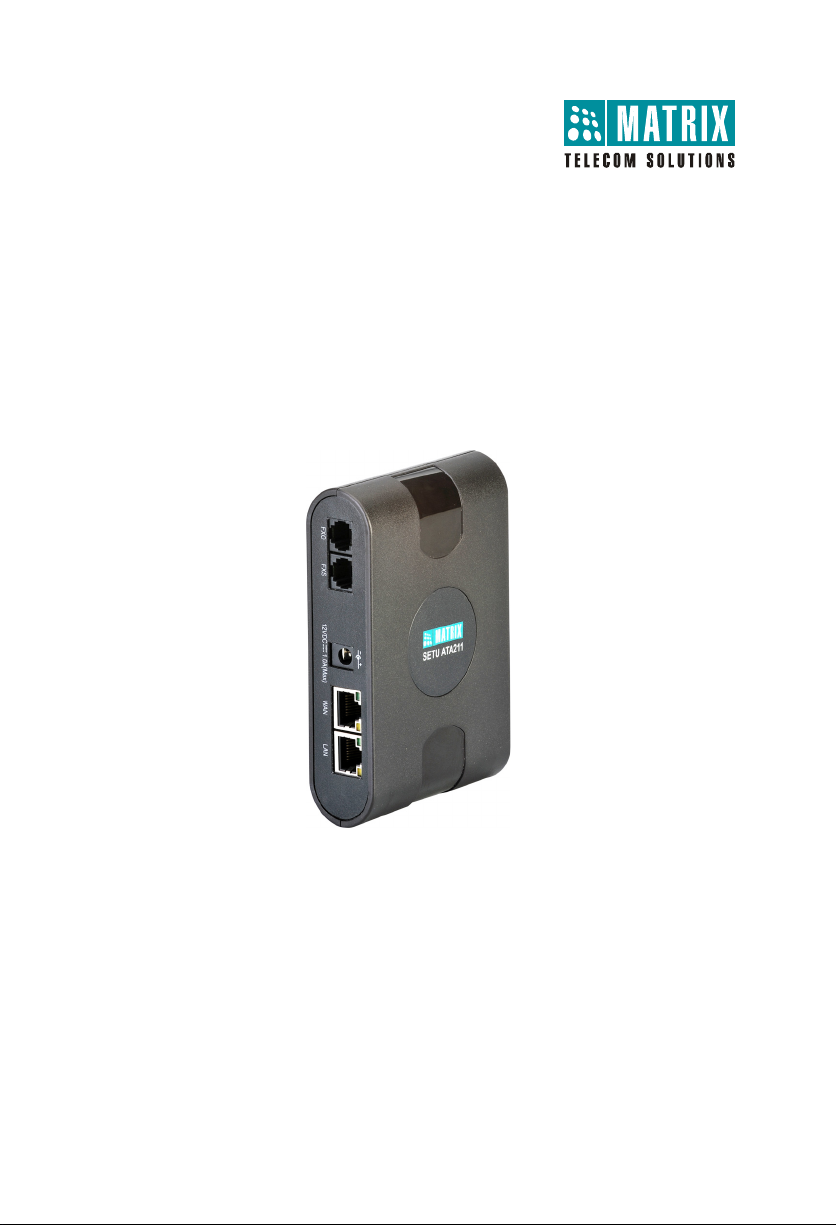
SETU ATA211
VoIP-FXS-FXO Adaptor
Quick Start
Package Contents
• SETU ATA211
• Adapter 12V, 1.25 Amp
• Ethernet Cables (RJ45 and RJ11)
• Two wall mounting screws and screw grips
• Warranty Card
• Quick Start and User Card
• CD (System Manual, Quick Start and User Card)
Page 4

Thank you for choosing SETU ATA211! Please read the instructions in this Quick
DSL Modem/
Router
PC/LAN
IP
POTS
Power
Adaptor
Start to install and configure the basic settings to make and receive VoIP and PSTN
calls.
Connecting SETU ATA211
Select an appropriate site and mount SETU ATA211.
Do not install the system at the places where shocks or vibrations are frequent or strong.
Use only the power adapter included in the SETU ATA211 package. Using an alternative nonqualified power adapter may possibly damage the unit.
• Connect a standalone PC/ LAN Switch to the LAN Port of SETU ATA211 using
the Ethernet cable.
• Connect the WAN Port of SETU ATA211 to the IP Network—A DSL modem/
router or LAN Switch—using the Ethernet cable.
4
Page 5

• Connect a telephone to the FXS Port of SETU ATA211, using a standard
telephone cable with an RJ11 plug.
• Connect the line from PSTN to the FXO Port of SETU ATA211.
• Connect the power adapter provided with SETU ATA211 to the power jack
labeled 12VDC-1A(MAX).
• Connect the adapter plug into a power outlet.
• Switch ON power.
Configuring SETU ATA211
SETU ATA211 provides an embedded web server with a graphic user Interface
(GUI), Jeeves, for configuration. You can access this embedded web server on
the PC you connected to the LAN Port.
The default IP Address of the LAN Port of SETU ATA211 is: 192.168.002.6
The default Subnet Mask of the LAN Port of SETU ATA211 is: 255.255.255.0
• Make sure your PC is in the same Subnet as the LAN Port of SETU ATA211.
Change the Subnet Mask of the PC, if necessary.
• Open a web browser (Internet Explorer Version 7 or higher or Mozilla Firefox 3.5
or higher) on the PC.
•Type 192.168.002.6, the default IP Address of the LAN Port of SETU ATA211 in
the address bar of the browser.
5
Page 6

The Login page opens.
You can also use the WAN Port of SETU ATA211 to access the embedded web server in the same
manner.
The default IP Address of the WAN Port of SETU ATA211 is: 192.168.001.171
The default Subnet Mask of the WAN Port of SETU ATA211 is: 255.255.255.0
SETU ATA211 offers two Login modes: Admin and User.
•The Admin mode allows you to configure the entire system, access all
system features and facilities.
•The User mode allows you configure, set or cancel specific features and
facilities.
To configure SETU ATA211,
6
Page 7

• In the Login As box, select Admin.
• In the Password field, enter 1234, the default Admin password.
• Click Login button.
• On successful login, the Home page will open.
The links Basic Settings, Advanced Settings, Supplementary Services and
Status, appear on the left pane.
Basic Settings are sufficient to get your SETU ATA211 into operation.
To set up and operate your system, quickly,
7
Page 8

• Click Basic Settings link.
The links to the different basic parameters appear on the left pane.
You may either use the Wizard to guide you through the configuration or
selectively configure the Basic Settings pages.
When you use selective configuration,
• Click Basic Settings link to expand.
• Click each parameter link, Region, SIP, FXO, FXS, Passwords, Network.
The selected parameter page opens.
• Set the desired values on the page.
• Click Submit to save your settings on the page.
8
Page 9

When you use the Wizard,
• Click the Wizard icon on the top right of your screen.
•The Next button takes you to the next page, saving the changes you made on
the current page.
•The Back button returns you to the previous page.
•The More button expands parameters on the page.
•The Less button collapses parameters on the page.
•The Default button assigns factory set values to all the parameters on the page
.
•The Quit button allows you to exit the Wizard at any stage, saving changes
you made before exiting.
Read the System Manual for detailed instructions.
9
Page 10

MATRIX COMSEC PVT. LTD.
Corporate Office:
394-GIDC, Makarpura, Vadodara - 390010, India.
Tel.:+91 265 2630555, Fax: +91 265 2636598
E-mail: Info@MatrixComSec.com
Factory:
39-GIDC, Waghodia - 391760, Dist. Vadodara, India.
Tel.: +91 2668 262056/57
Technical Support:
Tel.: +91 2668 263172/73, Fax: +91 2668 262631
E-mail: Support@MatrixComSec.com
www.MatrixComSec.com
Version 3, February 2011
 Loading...