

Page 1

1
E30 and E50
Service Manual
Page 2
2
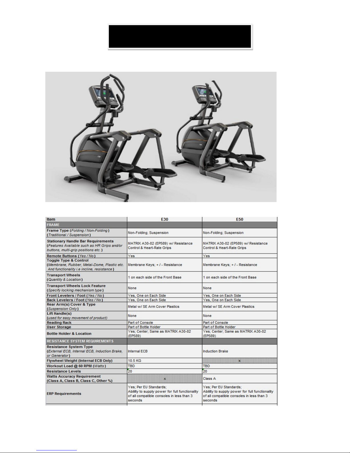
Matrix Retail E50 Matrix Retail E30
Specification
Production Browse
Page 3

3
Contents
CHAPTER 1: SERIAL NUMBER LOCATION………………………………………………………………..4
CHAPTER 2: TROUBLESHOOTING
2.1 Electrical Diagram…………………………………………………………………………………………...5
2.2 Board Connector Location …………………………………………………………………………………..6
2.3 Error Code Summary ………………………………………………………………………………………...8
2.4 Troubleshooting
2.4.1 Console Does Not Light up……………………………………………………………………………....9
2.4.2 Speed Does Not Display...……………………………………………………………………………….10
2.4.3 Heart Rate Issues………………………………………………………………………………………..11
2.4.4 Quick Key Issues ...………………….…………………………………………………………….. …..12
2.4.5 Noise Issues…………………………………………………………………………………………………………………………….13
2.4.6 No Resistance Or Incorrect Resistance……………………………………………………………….14
CHAPTER 3: PART REPLACEMENT GUIDE
3.1 Console Replacement…………………………………………………………………………………………………………………..16
3.2 Heart Rate Grip and Quick key Replacement……………………………………………………………………………....18
3.3 Cup Holder Replacement……………………………………………………………………………………………………………..19
3.4 Console Mast Replacement………………………………………………………………………………………………………….20
3.5 Handle Bar Replacement……………………………………………………………………………………………………………..21
3.6 Link Arm Replacement……… …………………………………………………………………………..22
3.7 Side Cover Replacement …………………………………………………………………………………………………………..…23
3.8 ECB Motor Board Replacement …………………………………………………………………………………………………..24
3.9 LCB board Replacement…..…………………..……………………………………………………… ..25
Page 4
4
CHAPTER 1: Serial Number Location
1.1 Serial Number Location
MATRIX E30/E50 EP FRAME
SERIAL NUMBER
Page 5
5
CHAPTER 2: Troubleshooting
2.1 ELECTRICAL DIAGRAM
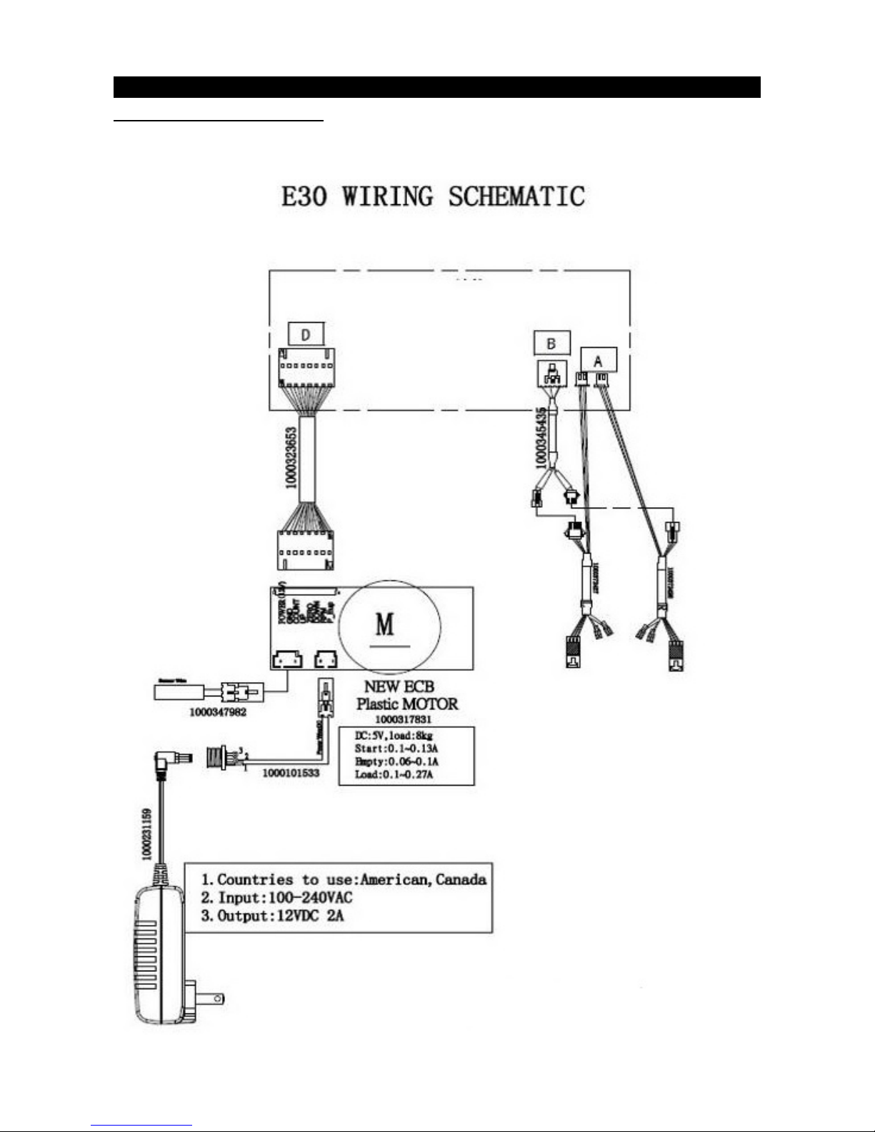
E30 Frame: (Fig.1)
Page 6
6
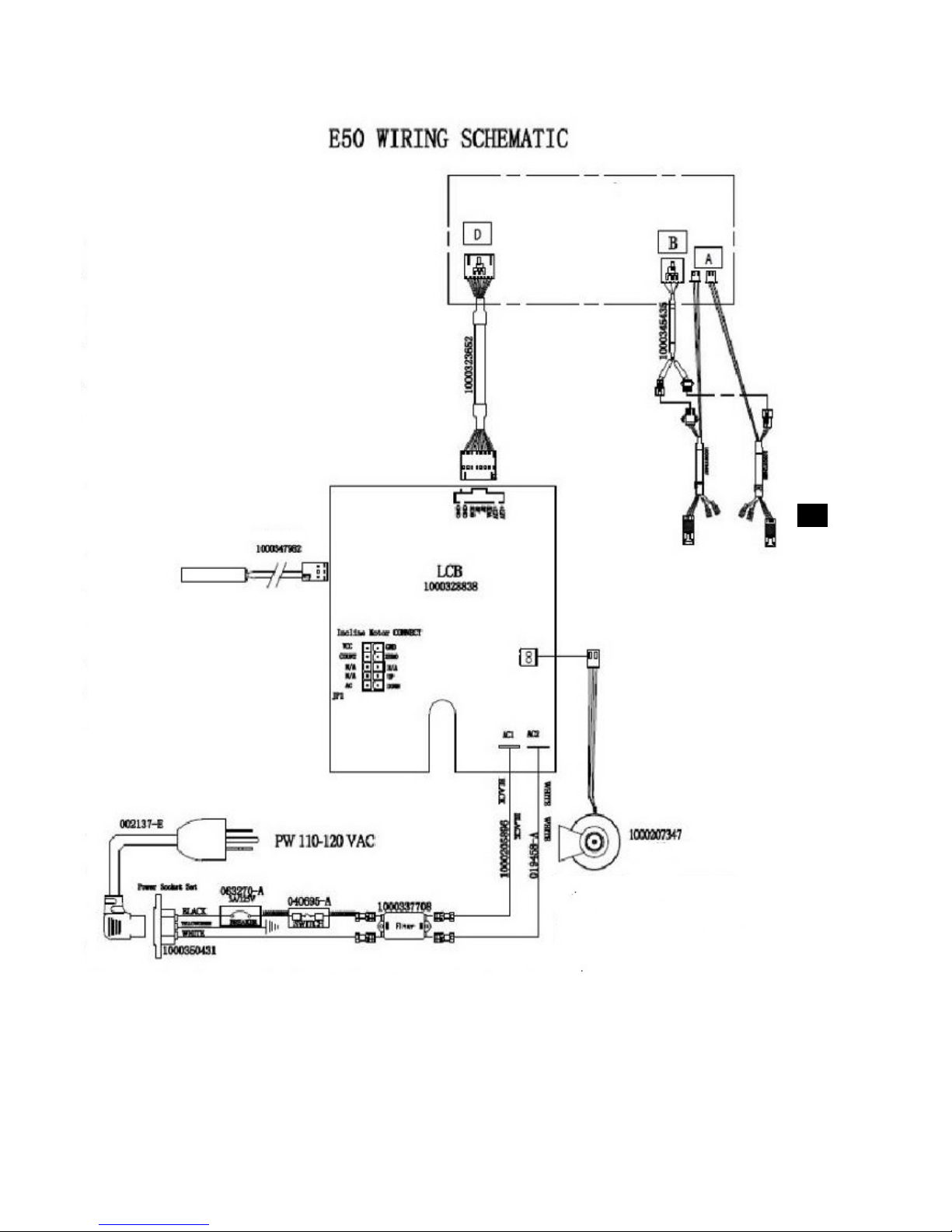
E50 Frame (Fig.2)
Page 7
7
(Fig-1)
CHAPTER 2: Troubleshooting
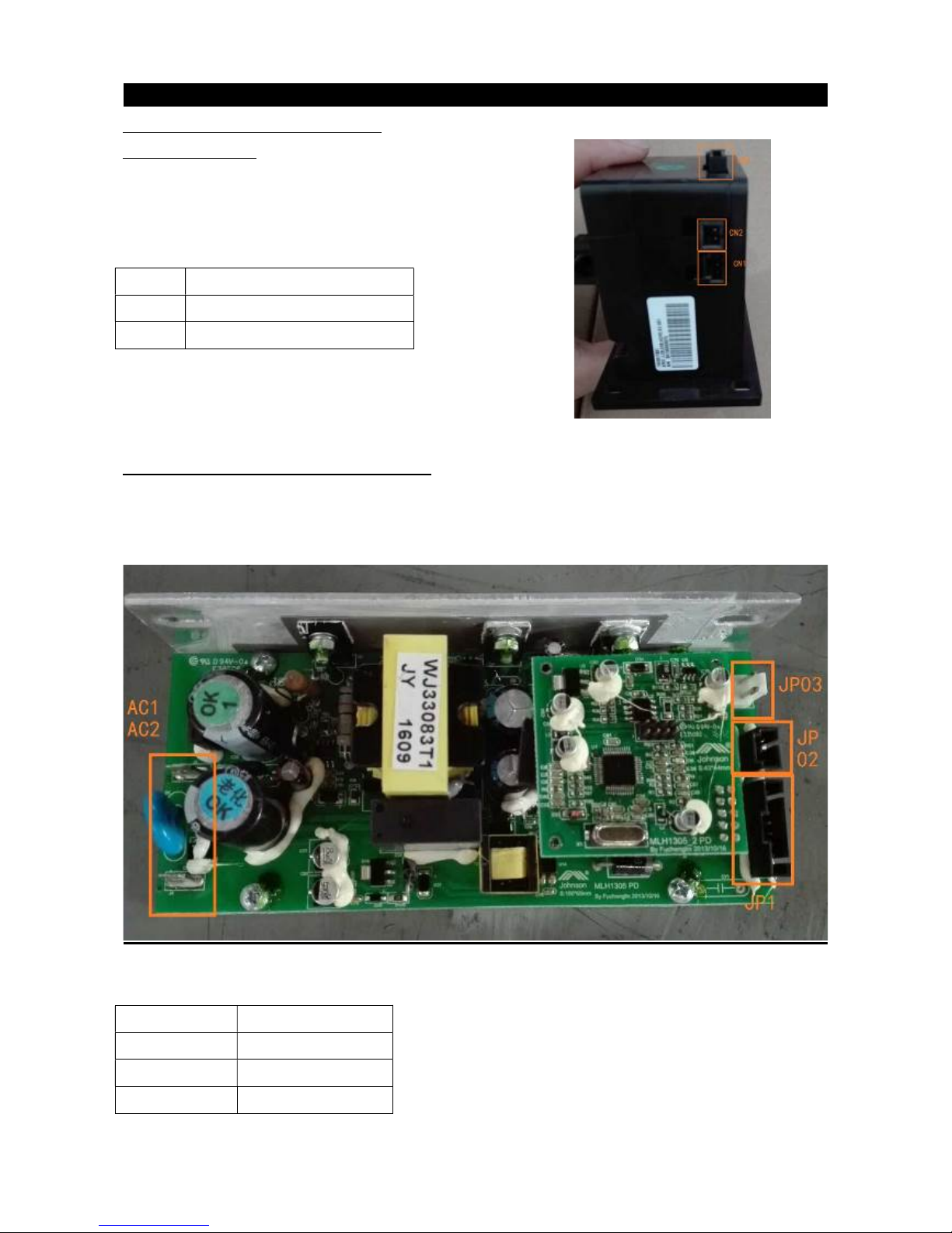
2.2. Board Connector Instruction:
2.2.1 ECB (E30):
ECB (Fig-1)
CN1 Speed sensor connection
CN2 Power adaptor connection
CN3 Console connection
2.2.2 Lower Control Board Connections
LCB (Fig-2)
Fig-2
AC1&AC2
JP1
JP02
JP03
AC power line input
LCB to console
Speed sensor
Resistance control
Page 8

8
2.3 Error Code Summaries:
Code Description Symptom Solution
1 CONSOLE DOES NOT LIGHT
UP
A .The power switch is in the on position, but
the console will not turn on.
b. The console is damaged or the console
cable is not connected properly.
c. Connection to the terminals on the lower
control board or console.
d. The lower control board is damaged and
does not output voltage.(E50)
e. The power adaptor is damage. (E30)
See section
2.4.1
2 SPEED DOES NOT DISPLAY The speed value does not display on console. 2.4.2
3 HEART RATE ISSUES A .Power contact between the user and HR
grips or HR strap.
b. The HR strap is at a low battery status.
c. The HR strap is damaged.
d. The HR grips are damaged.
e. The HR cannot display value.
2.4.3
4 QUICK KEY ISSUES a. No contact between keypad and overlay.
b. Keypad malfunction.
c. No contact between Keypad to console.
2.4.4
5 NOISE ISSUES Slapping / squeaking sound with each
footstep.
2.4.5
6 NO RESISTANCE OR
INCORRECT RESISTANCE
a. The resistance does not change.
b. The resistance is reversed or too heavy.
c. The keypad is damaged.
d. The console cable is either not connected
to the console or LCB or is damage.
e. The ECB is damaged.
2.4.6
Page 9

9
CHAPTER 2: Troubleshooting
2.4.1 TROUBLESHOOTING –CONSOLE DOES NOT LIGHT UP
SOLUTION:
1. The outlet the machine is plugged into is functional.
2. The correct power cord is being used. Only use the power cord included or provided by Customer
Tech Support.
3. The power cord is not pinched or damaged and is properly plugged into the outlet and the machine.
4. Remove the console and check if the console cable has good connected with the console.
Test console cable for 12VDC between pin1 & pin8. If power and connection is good, replace console.
5. Check to see if the console upper cable and console lower are connected well.
6. Remove the side cover and check to see if the cable is connected well.
7. For E30
7.1 Check to see if using correct adaptor: output 12VDC 2A.
7.2Remove the ECB to console cable (see Page7 figure 1). Use multi-meter to check the ECB CN3
Pin1/Pin2 (Positive) and Pin 8 (GND) if cannot see voltage +12 VDC. Install new ECB.
1 2 3 4 5 6 7 8
+12V +12V AD2 NC NC BD2
GND GND
CN3
For E50
7.3. Unplug the console cable from the LCB (see Page12 figure-2). Use multi-meter to check the
LCB JP1 Pin1 (Positive) and Pin 8 (Negative) to see if voltage is +12 VDC.
7.4 If a cannot see +12VDC, connect the LCB to Console cable. If still cannot see light on the screen,
the console is damage, install new console..
Page 10

10
CHAPTER 3: Troubleshooting
2.4.2 TROUBLESHOOTING – SPEED DOES NOT DISPLAY
SOLUTION:
For E30
1. Unplug power adaptor, remove the console, and check that all connections to the console are secure
and not damaged or pinched.
2. Remove the side cover and check to see if the sensor wire (CN01) is connected well and not damaged.
(Fig.1)
3. Check to see if one corner of the sensor is aligned with the magnet and ensure that the distance is less
than 5mm.(Fig-1)
4. Test speed sensor with multi-meter in Ohms on Pin1 & Pin2. While passing by magnet, take continuity
readings, open and close, and see if console can display speed.
5. Install new ECB Page7 (Fig-1) to see if console can display speed.
If still cannot display speed value, replace the console.
For E50
1. Unplug power cord, remove the console, and check that all connections to the console are secure and
not damaged or pinched.
2. Remove the side cover and check to see if the sensor wire (LCB JP02) is connected well.-(fig-2)
3. Check to see if one corner of the sensor is aligned with the magnet and ensure that the distance is
less than 5mm. (Fig-3)
5. Install new LCB Page7 (Fig-2) to see if console can display speed value. If still cannot display speed
value, replace the console.
Fig.1 Fig-2 Fig-3
Page 11

11
CHAPTER 3: Troubleshooting
2.4.3 TROUBLESHOOTING- HEART RATE ISSUES
SOLUTION:
a. Re-center the HR strap on user's chest, strap must have some moisture for good connection.
b. Replace the battery in the HR strap.
c. Wet the user's hand, and then reestablish contact with the HR grip.
d. Replace new HR grip if console can display proper HR rate.
With a multi-meter set for DC voltage, place one terminal on each of the HR grip plates. The HR
Grip should give a voltage reading of between 0.5 and 2.0VDC. If the voltage is not between 0.5
And 2.0VDC, remove the screws holding the HR grip together and check the connection of the
HR grip wiring.
e. Check a-d. If still the HR still does not display, install new console.
Page 12

12
CHAPTER 3: Troubleshooting
2.4.4 TROUBLESHOOTING- QUICK KEY ISSUES
SOLUTION:
Install new keypad and overlay.
Page 13

13
CHAPTER 3: Troubleshooting
2.4.5 TROUBLESHOOTING- NOISE ISSUES
SOLUTION:
1. Make sure that the console mast is tightly attached to the frame.
2. Make sure that the front stabilizer and rear stabilizer are tightly attached to the
frame.
3. Make sure that the pedal arms are tight.
4. Make sure that the handlebars are tight.
Page 14

14
CHAPTER 3: Troubleshooting
2.4.6 TROUBLESHOOTING- NO RESISTANCE OR INCORRECT RESISTANCE
SOLUTION:
1. Check if the console shows RPM value. If not, refer to solution for “SPEED DOES NOT DISPLAY”.
2. Turn on the console and check the ECB motor. In resistance level 1, the head of steel rope points
toward directs to top right side (around 45 degree). If the head of cable points toward the bottom left
side, the resistance will be reversed. Adjust the head of steel rope to the correct position.(Fig -1)
Fig-1
3.Press key up “ ↑” to increase the resistance.
A) If ECB motor cannot move but the console screen shows change, the ECB motor or console
cable may be defective. Be sure that the console cable is inserted in ECB motor. Use a
multi-meter to measure the ECB CN3. Pin3 (POS) and Pin5&6 (GND) : normally it should be DC
6V. If no output, test the console cable. Install the console cable. If output is 6VDC, the ECB
motor is defective. Replace ECB.
B) If the ECB motor can move, the resistance can be adjusted. If the resistance is still too heavy,
check the gap (Fig-1) between the orange block and the bottom. It should be within 1-2 mm. If the
gap is bigger than 1-2 mm, the resistance will be heavier than normal. Adjust the cable to the
correct gap.
4.If all above conditions are met, and the resistance is still heavy, inside magnet is defective. Replace
the inside magnet as the last step.
Page 15

15
For E50
Unplug the cable at J03 and be sure console cable is inserted in JP1 (Fig-1) .Use multi-meter set to DC
voltage to check the voltage of JP03 pin1& Pin2. If cannot measure any voltage, replace LCB. If you measure
any voltage replace console. If you can measure any voltage in JP03 but resistance still does not function,
test the ECB (Fig-2) .
Fig-1 Fig-2
Page 16

16
CHAPTER 3: Part Replacement Guide
3.1 CONSOLE REPLACEMENT
1) For XIR/XER: Remove the 5 screws holding the console back cover to the frame. (Fig-1).
2) For all consoles: remove the 4 screws holding the console to the frame (E30). (Fig-2& Fig-4).
3) Disconnect the console cable and HR connections then remove the console. (Fig-3)
Fig-1 Fig-2
Fig-3 Fig-4
3) Reinstall the wire connections to the console.
4) Carefully push the wires into the console and mast until they are clear of the console mast connection.
Attach the console to the mast using the 4 screws.
Page 17

17
CHAPTER 3: Part Replacement Guide
3.2 HEART RATE GRIP and QUICK KEY REPLACEMENT(E30&E50)
A. HEART RATE GRIP.
1) Remove the 3 screws from heart rate plastic housing. (Fig-1)
2) Open the plastic housing. (Fig-2)
3) Disconnected the wires from HR plates and quick key connector. (Fig-3)
4) Remove the bad HR plates and insert new HR plates.
5) Connected the wire to new HR plates and quick key connector.
6) Close the plastic housing to the handlebar and fasten the screws, making sure the wires are not being
pinched.
Fig-1 Fig-2
Fig-3 Fig-4
Quick key
Heart rate
Page 18

18
B .QUICK KEY
1) Remove the 3 screws from plastic housing. (Page 16, Fig-1)
2) Open the plastic housing.(Page16,Fig-2)
3) Disconnect the wires from HR plates and quick key connector. (Page16, Fig-3)
4) Remove the overlay from front plastic cover and slowly pull new keypad into the housing. (Page16, Fig-4)
5) Connect the wires to HR plates and quick key connector. (Page16, Fig-3)
6) Fasten 3 screws to the plastic housing, making sure wires are not being pinched.
Page 19

19
CHAPTER3: Part Replacement Guide
3.3 CUP HOLDER REPLACEMENT(E30&E50)
1) Confirm cup holder location. (Fig-1)
2) Remove the 3 screws from both sides. (Fig-2)
3) Remove the bad cup holder and install new cup holder.
4) Fasten the 4 screws.
Fig-1 Fig-2
Page 20

20
CHAPTER 3: Part Replacement Guide
3.4 CONSOLE MAST REPLACEMENT (E30&E50)
1) Remove console. (See Section 3.1 )
2) Remove dual action handlebars.(See section 3.5)
3) Remove the cover of console mast by pulling back on the cover. (Fig-1 and Fig-2)
Fig-1 Fig-2
4) Remove side cover screws and remove side cover.
5) Remove the 4 bolts holding the console mast, making sure to guide console cable to ensure it is not
damaged during removal.(Fig-3 and Fig-4 and Fig-5D)
Fig- 3 Fig-4 Fig-5
Page 21

21
CHAPTER 3: Part Replacement Guide
3.5 HANDLE BAR REPLACEMENT (E30&E50)
1) Remove the lower nut and bolt connecting the handlebar to lower link arm. (Fig-1 and Fig-2)
2) Remove the upper bolts connecting the handlebar to the console mast.
3) Take the arm set off. (Fig-3)
4) Reverse step to reinstall.
Fig-1 Fig-2
Fig-3
Page 22

22
CHAPTER 3: Part Replacement Guide
3.6 LINK ARM REPLACEMENT (E30/E50)
1) Open the side cover.
2) Remove the nut and bolt to remove the link arm from the handlebar -(Fig-1~ Fig-5 )
Fig-1 Fig -2
3) Remove the bolt securing the link arm to the swing arm.
4) Remove footplate if necessary.
5) Reverse order to install link arm.
Fig-3 Fig-4 Fig-5
Page 23

23
CHAPTER3: Part Replacement Guide
3.7 SIDE COVER REPLACEMENT
1) Remove the cover of console mast. (Fig-1 and Fig-2)
Fig-1 Fig-2
1) Remove the 6 screws in the side cover. (Fig-3 and Fig-4 and Fig-5)
Fig-3 Fig-4 Fig-5
2) Install new side cover and fasten screws. (Fig-6)
Fig-6
Page 24

24
CHAPTER 3: Part Replacement Guide
3.8 ECB MOTOR REPLACEMENT(E30)
1) Remove the side cover and handlebar.
2) If you are replacing a defective ECB motor, test the new ECB motor before completely removing:
Connect the wire and test by running resistance up and down. If you must replace the ECB motor,
installation is much easier if the motor is at highest resistance.
3) Remove ECB screws. (Fig-1)
4) Replace new ECB & insert connection test. (Fig-2 and Fig-3)
5) Fasten handlebar and side cover.
Fig-1 Fig-2
6 Adjust the cable to proper mounting position.
Fig-3
Page 25

25
CHAPTER 3: Part Replacement Guide
3.09 LCB MOTOR REPLACEMENT (E50)
1) Remove the side cover and handlebar (see section 3.7 and section 3.5)-(Fig-1)
2) Remove LCB screws (Fig- 2 and Fig-3)
3) Install new LCB & insert connections. (Fig 2 and Fig 4)
4) Fasten handlebar and side cover.
5) Plug in AC power line.
Fig-1 Fig-2
Fig-3 Fig -4
 Loading...