

Page 1

H7XI-01 TREADMILL
SERVICE MANUAL
Page 2

TABLE OF CONTENTS
CHAPTER 1: SERIAL NUMBER LOCATION ........................................................... 1
CHAPTER 2: IMPORTANT SAFETY INSTRUCTIONS
2.1 Read and Save These Instructions ............................................................................ 3
2.2 Electrical Requirements ............................................................................................. 4
CHAPTER 3: PREVENTATIVE MAINTENANCE
3.1 Recommended Cleaning Tips .................................................................................... 5
3.2 Check for Damaged Parts ......................................................................................... 5
3.3 Care and Maintenance Instructions ........................................................................... 6
3.4 Touch Screen Care & Cleaning .................................................................................. 7
CHAPTER 4: CONSOLE OVERLAY AND WORKOUT DESCRIPTION
4.1 Console Description ................................................................................................... 8
4.2 Workout Setup Steps .................................................................................................. 9
CHAPTER 5: MANAGER MODE
5.1 Using Manager Mode ................................................................................................ 10
5.2 Manager Mode - General ........................................................................................... 11
5.3 Manager Mode - Workout .......................................................................................... 14
5.4 Manager Mode - Setup Defaults ................................................................................ 16
5.5 Manager Mode - Asset Management ......................................................................... 18
5.6 Manager Mode - Weather .......................................................................................... 18
5.7 Manager Mode - TV ................................................................................................... 19
5.8 Manager Mode - Applications .................................................................................... 20
5.9 Manager Mode - Hardware ........................................................................................ 21
5.10 Manager Mode - Service ............................................................................................ 22
CHAPTER 6: ENGINEERING MODE
6.1 Using Engineering Mode ........................................................................................... 23
6.2 Engineering Mode - General ...................................................................................... 24
6.3 Engineering Mode - Workout ..................................................................................... 27
6.4 Engineering Mode - Setup Defaults ........................................................................... 29
6.5 Engineering Mode - Network ..................................................................................... 30
6.6 Engineering Mode - Asset Management .................................................................... 31
6.7 Engineering Mode - Weather ..................................................................................... 32
6.8 Engineering Mode - TV .............................................................................................. 32
6.9 Engineering Mode - Applications ................................................................................ 35
6.10 Engineering Mode - Hardware ................................................................................... 35
6.11 Engineering Mode - Service ....................................................................................... 36
6.12 Engineering Mode - Errors ......................................................................................... 36
CHAPTER 7: SERVICE MODE
7.1 Using Service Mode. .................................................................................................. 37
7.2 Service Mode - General ............................................................................................. 38
7.3 Service Mode - Workout ............................................................................................. 41
7.4 Service Mode - Setup Defaults .................................................................................. 43
7.5 Service Mode - Update .............................................................................................. 44
7.6 Service Mode - Network ............................................................................................. 45
7.7 Service Mode - Asset Management ........................................................................... 46
7.8 Service Mode - Weather ............................................................................................ 46
7.9 Service Mode - TV...................................................................................................... 47
7.10 Service Mode - Applications ....................................................................................... 48
7.11 Service Mode - Hardware ........................................................................................... 49
7.12 Service Mode - Virtual Active ..................................................................................... 51
7.13 Service Mode - Management ..................................................................................... 51
7.14 Service Mode - Service .............................................................................................. 52
7.15 Service Mode - Errors ................................................................................................ 52
7.16 Service Mode - Netpulse ............................................................................................ 53
7.17 Matrix fitness 7xi series feature access codes ........................................................... 54
Page 3

TABLE OF CONTENTS
CHAPTER 8: TROUBLESHOOTING
8.1 Electrical Diagram ...................................................................................................... 55
8.2 LCB LED Indicators .................................................................................................... 59
8.3 LCB Wiring Connections ............................................................................................. 60
8.4 Troubleshooting - Error 04A0 ...................................................................................... 61
8.5 Troubleshooting - Error 04B0 ...................................................................................... 62
8.6 Troubleshooting - Error 0248 ...................................................................................... 63
8.7 Troubleshooting - Error 02B4 ...................................................................................... 64
8.8 Troubleshooting - Error 02AB ..................................................................................... 65
8.9 Troubleshooting - Error 01AC ..................................................................................... 66
8.10 Troubleshooting – No Resistance Issues ................................................................... 67
8.11 Troubleshooting - Heart Rate Issues .......................................................................... 68
8.12 TV Troubleshooting - Overview ................................................................................... 69
8.13 TV Troubleshooting - Picture Fuzzy or Unclear .......................................................... 70
8.14 TV Troubleshooting - TV Will Not Turn On ................................................................. 71
8.15 TV Troubleshooting - Entertainment Keypad Issues .................................................. 72
CHAPTER 9: PART REPLACEMENT GUIDE
9.1 Console Replacement ..................................................................................................... 73
9.2 Heart Rate Handlebar Replacement ............................................................................. 74
9.3 Heart Rate Grip Replacement ....................................................................................... 75
9.4 Cup Holder Replacement ............................................................................................... 76
9.5 Console Keypad / Overlay Replacement ....................................................................... 77
9.6 Console Mast Removal ................................................................................................... 79
9.7 Seat Pad Replacement ................................................................................................... 80
9.8 Back Pad Replacement .................................................................................................. 81
9.9 Stationary Handlebar Replacement ................................................................................ 82
9.10 Pedal Replacement ........................................................................................................ 83
9.11 Rear Shrouds Replacement ........................................................................................... 84
9.12 Front Shrouds Replacement ........................................................................................... 85
9.13 Lower Control Board Replacement ............................................................................... 86
9.14 Battery Replacement ...................................................................................................... 87
9.15 Drive Belt Replacement ................................................................................................. 88
9.16 Generator Belt Replacement .......................................................................................... 89
9.17 Generator Replacement.................................................................................................. 90
9.18 Pulley Axle Set Replacement ......................................................................................... 91
9.19 Crank Axle Set Replacement .......................................................................................... 93
9.20 Rear Stabilizer Replacement .......................................................................................... 94
9.21 Front Stabilizer Replacement ......................................................................................... 95
9.22 Testing the Bike ............................................................................................................... 96
CHAPTER 10: BIKE SPECIFICATIONS AND ASSEMBLY GUIDE
10.1 H7xi-01 Bike Specifications ........................................................................................ 97
10.2 Fasteners and Assembly Tools ................................................................................... 98
10.3 Assembly Instructions ................................................................................................ 99
10.4 Adjusting the Pedal Straps and Seat .......................................................................... 105
10.5 Leveling the Bike ......................................................................................................... 106
10.6 TV Programming Instructions ..................................................................................... 107
10.7
10.8 Netpulse & AM Setting SOP ...................................................................................... 117
CHAPTER 11: SOFTWARE UPGRADE GUIDE
11.1 Software Upgrade Instructions .................................................................................... 129
Using Update Manager ............................................................................................... 113
III
Page 4
1.1 SERIAL NUMBER LOCATION
CHAPTER 1: SERIAL NUMBER LOCATION
A serial number plate is located behind the seat in the seat track. There is also a serial number tag on the middle of the main frame pointed
towards the floor.
1
Page 5

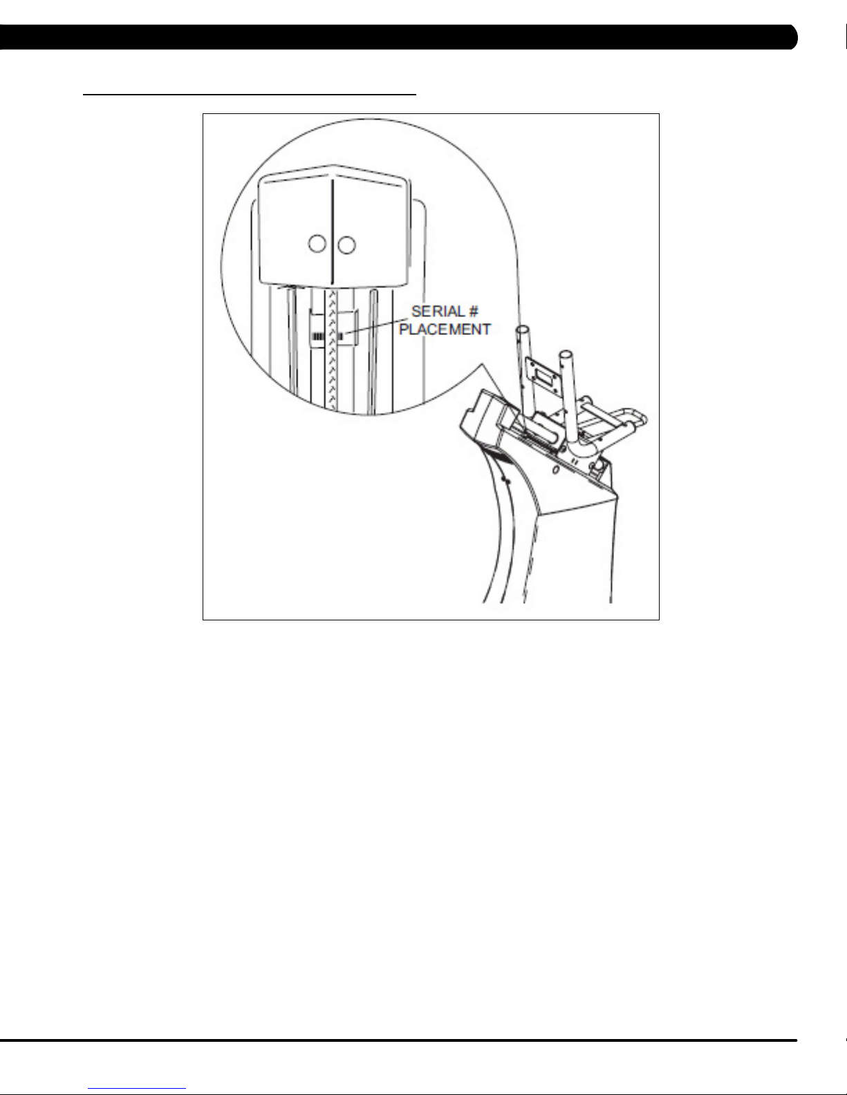
CHAPTER 1: SERIAL NUMBER LOCATION
1.1 SERIAL NUMBER LOCATION - CONTINUED
CONSOLE SERIAL NUMBER LOCATION
CONSOLE SERIAL NUMBER LOCATION
2
Page 6

CHAPTER 2: IMPORTANT SAFETY INSTRUCTIONS
2.1 READ AND SAVE THESE INSTRUCTIONS
To ensure your safety and protect the equipment, read all
instructions before operating the MATRIX H7xi Bike.
To ensure proper use of the Matrix H7xi Bike, make sure that all
users read this manual. Remind the users that before undertaking
any fitness program, they should obtain complete physical
examinations from their physicians. If, at any time while exercising,
the user experiences dizziness, pain, or shortness of breath,
nausea or feels faint, he or she must stop immediately.
* This bike is only to be used for its intended purpose described in this
manual. Do not use attachments that have not been recommended
by Matrix.
* Never drop or insert objects into any opening. Keep hands away
from moving parts. If the item cannot be reached, contact a Matrix
authorized dealer for assistance.
* Never operate the unit if it is damaged, not working properly, when
it has been dropped, or has been dropped in water.
* Keep hands and feet clear at all times from moving parts to avoid
injury.
* Do not use this product outdoors, near swimming pools or in areas
of high humidity.
* Do not operate where aerosol (spray) products are being used or
when oxygen is being administered.
* Do not use this product in bare feet. Do not wear shoes with heels,
leather soles, cleats, or spikes while exercising.
CAUTION! If you experience chest pains, nausea, dizziness,
or shortness of breath, stop exercising immediately and con
sult your physician before continuing.
CAUTION! Any changes or modifications to this equipment
could void the product warranty.
-
* Do not remove the side covers. Service should only be done by an
authorized service technician.
* Close supervision is necessary when used near children, invalids,
or disabled people.
* When the bike is in use, young children and pets should be kept at
least 3 meters / 10 feet away.
* Assemble and operate the bike on a solid, level surface.
* Never face backward while using the Matrix H7xi Bike.
* Use the stationary handlebars when mounting or dismounting the
bike.
* Do not wear clothing that might catch on any moving parts of this
bike.
3
Page 7
CHAPTER 2: IMPORTANT SAFETY INFORMATION
2.2 ELECTRICAL REQUIREMENTS
DEDICATED CIRCUIT AND ELECTRICAL INFO
A “Dedicated Circuit” means that each outlet you plug into should not have anything else running on that same circuit. The easiest way to verify
this is to locate the main circuit breaker box, and turn off the breaker(s) one at a time. Once a breaker has been turned off, the only thing that
should not have power to it are the units in question. No lamps, vending machines, fans, sound systems, or any other item should lose power
when you perform this test.
Non-looped (isolated) neutral/grounding means that each circuit must have an individual neutral/ground connection coming from it, and
terminating at an approved earth ground. You cannot “jumper” a single neutral/ground from one circuit to the next.
ELECTRICAL REQUIREMENTS
For your safety and to ensure good unit performance, the ground on this circuit must be non-looped (isolated). Please refer to NEC article 21021 and 210-23. Any alterations to the standard power cord provided could void all warranties of this product.
The 3x, 5x and 7xe bikes are designed to be self-powered and do not require an external power supply source to operate. Without an external
power supply, the console’s start-up time may be delayed. Add-on TV’s and other console accessories will increase the time needed for startup. An external power supply will ensure power is provided to the console at all times and is recommended when add-on accessories are used.
For units with an integrated TV (like the 7xe and 7xi), the TV power requirements are included in the unit. An RG6 coaxial cable with ‘F Type’
compression fittings on each end will need to be connected to the cardio unit and the video source. Additional power requirements are not
needed for the add-on digital TV (3x and 5x). For units with an add-on PCTV (3x and 5x), the TV power requirements are separate.
NOTE: ALL UNITS WITH VIRTUAL ACTIVE™ MUST BE POWERED!
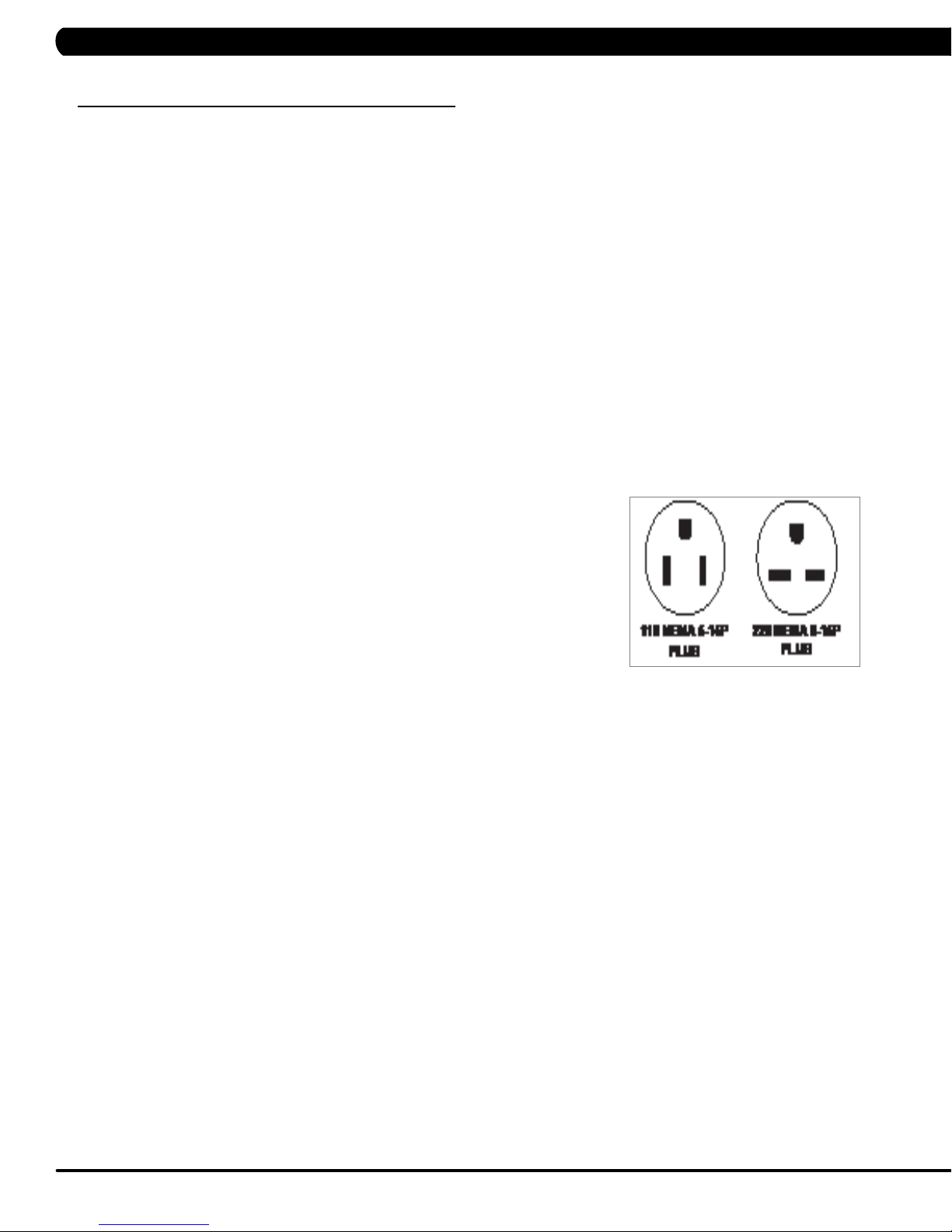
110 V UNITS
All Matrix 3x, 5x, 7xe and 7xi 110 V bikes require the use of a 100-125 V, 60 Hz and a 15 A
“Dedicated Circuit”, with a non-looped (isolated) neutral/ground for power. This outlet should be a
NEMA 5-15R and have the same configuration as the plug. No adapter should be used with this
product. These bikes can be daisy-chained together with up to 4 units per 15 A dedicated circuit.
Matrix daisy-chain cord adapters are sold separately.
220 V UNITS
All Matrix 3x, 5x, 7xe and 7xi 220 V bikes require the use of a 216-250 V, 50 Hz and a 15 A
“Dedicated Circuit”, with a non-looped (isolated) neutral/ground for power. This outlet should be a
NEMA 6-15R and have the same configuration as the plug. No adapter should be used with this
product. These bikes can be daisy-chained together with up to 4 units per 15 A dedicated circuit.
Matrix daisy-chain cord adapters are sold separately.
GROUNDING INSTRUCTIONS
The unit must be grounded. If it should malfunction or breakdown, grounding provides a path of least resistance for electric current to reduce
the risk of electric shock. The unit is equipped with a cord having an equipment-grounding conductor and a grounding plug. The plug must be
plugged into an appropriate outlet that is properly installed and grounded in accordance with all local codes and ordinances. If the user does
not follow these grounding instructions, the user could void the Matrix limited warranty.
ADDITIONAL ELECTRICAL INFO
In addition to the dedicated circuit requirement, the proper gauge wire must be used from the circuit breaker box, to each outlet that will have
the maximum number of units running off of it. If the distance from the circuit breaker box to each outlet, is 100 ft (30.5 m) or less, then 12
gauge wire should be used. For distances greater than 100 ft (30.5 m) from the circuit breaker box to the outlet, a 10 gauge wire should be
used.
North American power cord plugs shown.
Depending on your country, the plug type may vary.
ENERGY SAVING / LOW- POWER MODE
All units are configured with the ability to enter into an energy saving / low-power mode when the unit has not been in use for a specified period
of time. Additional time may be required to fully reactivate this unit once it has entered the low-power mode. This energy saving feature may be
enabled or disabled from within the ‘Manager Mode’ or ‘Engineering Mode.
4
Page 8

CHAPTER 3: PREVENTATIVE MAINTENANCE
3.1 RECOMMENDED CLEANING TIPS
In order to maximize life span, and minimize down time, all Matrix Fitness Equipment requires regularly
scheduled cleaning.
YOU WILL NEED:
- Mild dish soap and water mixture in a spray bottle (10:1 water to soap ratio).
- Lint free 100% cotton cleaning cloths or Microfiber cleaning cloths.
- Vacuum / Shop Vac with extendable hose and soft brush attachment.
- Super Lube Multi Purpose Synthetic Lubricant with Syncolon® (PTFE) Aerosol - www.super-lube.com/sythetic-aerosol-spray-ezp-46.html.
- Computer or LCD / LED screen cleaner
- Corrosion Block (available from Matrix - part # ZMS4001374).
DAILY:
1. Wipe down the unit after each use with a mild dish soap and water mixture. NOTE: Spray the soap / water mixture onto the cloth.
NEVER spray directly onto the equipment. We recommend that you do NOT allow customers to use spray bottles to clean the equipment. If
the cleaner is sprayed directly on the equipment or over spray is present, it may cause your equipment to rust and / or cause damage to con
sole overlays.
WEEKLY:
1. With a clean dry 100% lint free cloth and water / soap mixture, wipe down the entire frame so it is free of dust, dirt, and sweat.
2. With a clean dry 100% lint free cloth and water / soap mixture, wipe down the entire console area including the hand grips and hand rails.
3. Use a computer screen cleaner or LCD / LED screen cleaner on the touch portion of the console (see Section 3.4).
-
MONTHLY:
1. Vacuum under and around the Bike. If you need to move it, unplug the unit first.
2. With a clean dry 100% lint free cloth and water / soap mixture, wipe down the seat guide rods. Spray Super-Lube onto a 100% lint free
cloth and wipe down the guide rods that the seat slides up and down on (Figure A).
3. Apply Corrosion Block to the metal part of the iPod cable.
FIGURE A
3.2 CHECK FOR DAMAGED PARTS
DO NOT use any equipment that is damaged or has worn or broken parts. Use only replacement parts supplied by Matrix Fitness Systems.
MAINTAIN LABELS AND NAMEPLATES. Do not remove labels for any reason. They contain important information. If unreadable or missing,
contact Matrix Fitness Systems for a replacement. 1-866-693-4863, www.matrixfitness.com
MAINTAIN ALL EQUIPMENT Preventative maintenance is the key to smooth operating equipment. Equipment needs to be inspected at regular
intervals. Defective components must be replaced immediately. Improperly working equipment must be kept out of use until it is repaired.
Ensure that any person(s) making adjustments or performing maintenance or repair of any kind is qualified to do so. Matrix Fitness Systems will
provide service and maintenance training at our corporate facility upon request or in the field if proper arrangements are made.
5
Page 9

CHAPTER 3: PREVENTATIVE MAINTENANCE
3.3 CARE AND MAINTENANCE INSTRUCTIONS
In order to maximize life span, and minimize down time, all MATRIX equipment requires regular maintenance items performed on a scheduled
basis. This section contains detailed instructions on how to perform these items and the frequency of which they should be done. Some basic
tools and supplies will be necessary to perform these tasks which include (but may not be limited to):
* Metric Allen wrenches
* #2 Phillips head screwdriver
* Adjustable wrench
* Commercial Pedal wrench (available from Matrix - part # ZMS4001254)
* Teflon based spray lubricant such as “Super Lube”, or other Matrix approved product
* Computer or LCD / LED screen cleaner
You may periodically see an addendum to this document, as the Matrix Technical Support Team identifies items that require specific attention, the
latest version will always be available on the Matrix website, www.matrixfitness.com
DAILY MAINTENANCE ITEMS
1. Attempt to wobble the unit back and forth, level if needed (see Section 10.5).
MONTHLY MAINTENANCE ITEMS
1. Check the pedal straps for damage.
2. Clean the grooves on the foot pedals.
QUARTERLY MAINTENANCE ITEMS
1. Frequently vacuum the floor beneath the unit to prevent the accumulation of dust and dirt which can affect the smooth operation of the unit.
2. Check that the pedal and crank assembly are tight with no free play or wobble in them. Make sure to use a commercial grade pedal wrench
to get the pedals as tight as possible.
3. Check the condition of the seat upholstery. Make sure that the seat adjustment mechanism is operating correctly.
4. Clean and lubricate the seat guide rods with Super Lube.
YEARLY MAINTENANCE ITEMS
1. Remove the front shrouds and check the belts for damage, alignment, and proper tension.
6
Page 10

CHAPTER 3: PREVENTATIVE MAINTENANCE
3.4 TOUCH SCREEN CARE & CLEANING
TOUCH SCREEN CARE AND CLEANING
* The touch screen requires very little maintenance. We recommend that you periodically clean the touch screen surface with a clean dry 100%
lint free cloth and water / soap mixture or a computer or LCD / LED screen cleaner.
* It is very important to avoid using any other chemical on the touch screen.
* Always dampen the cloth and clean the screen. Do not spray the water / soap mixture on the screen itself, the drips can seep into the display
or stain the bezel.
* After cleaning, make sure the surface is dry. There should not be any left over solvent to seep into the display.
* It is very important to handle the touch screen with care. Do not use excessive force when cleaning.
* Do not use any sharp materials to clean the touch screen surfaces.
* Do not use high pressure air, water, or steam to clean the touch screen surface.
7
Page 11

CHAPTER 4: CONSOLE OVERLAY AND WORKOUT DESCRIPTION
4.1 CONSOLE DESCRIPTION
The H7xi has a fully integrated touch screen display. All information required for workouts is explained on screen. Exploration of the interface is
highly encouraged. The information explaining how to program for various workouts will give an explanation about the contents of each screen.
GO: One touch Start.
STOP: Ends workout and shows workout summary data.
COOL DOWN
Workouts 19 minutes and shorter will have a cool down length of 2 minutes. Workouts 20 minutes and longer will have a cool down length of 5
minutes.
(displayed on-screen during workout): Puts unit into Cool Down mode. Cool Down time is dependent on the length of the workout.
H7XI ENTERTAINMENT ZONE
iPOD®: Will take the user directly to the iPod screen to allow for iPod control and playlist selection.
VOLUME UP / DOWN: Adjusts the volume output through the headphone jack of the integrated console TV or iPod output.
NUMBER KEYPAD: Allows for easy TV channel selections.
CHANNEL UP / DOWN: Allows for channel selection.
DISPLAY MODE: Allows user to cycle through console display options, iPod, TV, or profile display.
LAST CHANNEL: Allows the user to cycle between the current channel and the previous channel viewed.
CC/MUTE:
Mutes sound and turns closed captioning on or off.
8
Page 12
CHAPTER 4: CONSOLE OVERLAY AND WORKOUT DESCRIPTION
4.2 WORKOUT SETUP STEPS
To set up a workout, press the touch screen over the program you would like to use and then follow the prompts to begin your workout.
GO - Press to immediately begin a workout. Workout, resistance level, and time will automatically go to default settings. Pressing GO will not
prompt user for age, weight, or level settings.
MANUAL - Manual allows the user to input more information while defining their own workout. Calorie expenditure will be more accurate when
inputting information in Manual than by pressing GO.
FAT BURN - Fat burn is a level based program that is designed to help users burn fat through various resistance level changes.
ROLLING HILLS - The Rolling Hills program is a level based program that automatically adjusts the resistance level to simulate real terrain.
INTERVALS - The Intervals program is a level based program that automatically adjusts the resistance of the machine from low to high
intensity settings at regular intervals.
RANDOM - Random is a level based workout that randomly adjusts the resistance of the machine.
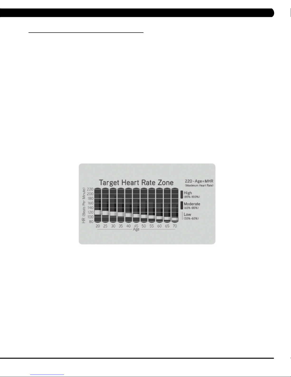
TARGET HEART RATE - The Matrix H7xi bike comes with standard digital contact heart rate sensors and are POLAR telemetry compatible.
The heart rate control workout mode allows the user to program their desired heart rate zone, and the bike will automatically adjust the level based
upon the user's heart rate. The heart rate zone is calculated using the following equation: (220-Age)8%=target heart rate zone. The user must
wear a POLAR telemetric strap or continually hold onto the contact heart rate grips for this workout.
Locate the metal sensors on the handlebars of the bike. Notice that there are two separate pieces of metal on each grip. You must be making
contact with both pieces of each grip to get an accurate heart rate reading. You can grab these sensors in any program to view your current heart
rate.
FITNESS TEST -The Cooper Fitness Test measures cardiovascular fitness and proves an estimated sub-maximal VO2 result. It is based on
power output according to ACSM standards and was developed by the Cooper Institute© (www.cooperinstitute.org). User RPMs must remain
between 60-80 RPM during the test. The test will end when the user can no longer maintain this speed. Use of a heart rate strap is optional but
provides more data.
The test starts at a low intensity level and gradually increases in intensity (difficulty) every 2 minutes. As it increases, the user must maintain
60-80 RPM to advance to the next level. The test could take upwards of 30+ minutes for very fit individuals. Once the test ends a recovery period
(cool down) will begin and the user's results are calculated and displayed. Results are based on the number of stages completed. Incline will not
be adjustable during the test.
STAGE COMPLETE:
1 Well Below Average
2 Well Below Average
3 Below Average
4 Below Average
5 Average
6 Average
7 Above Average
8 Above Average
9+ Well Above Average
CONSTANT WATTS - Constant Watts is a unique program that allows you to vary your cadence or RPM and the bike's resistance level will
adjust accordingly to your selected goal. The quicker you pedal, the less resistance for the goal selected.
9
Page 13
5.1 USING MANAGER MODE
CHAPTER 5: MANAGER MODE
1) To enter Manager Mode, press "ENTER, 1, 0, 0, 1, ENTER" on the number keypad and Manager Mode will appear on the display.
2) Manager Mode is divided into 9 tabs, located on the left side of the screen. They are General, Workout, Setup Defaults, Asset Management,
Weather, TV, Applications, Hardware and Service.
3) Choose a tab by touching the screen over the desired tab.
4) Each of the tabs has options that will appear once you have chosen that particular tab.
5) Press the "HOME" button or the EMERGENCY STOP to exit Manager Mode.
10
Page 14
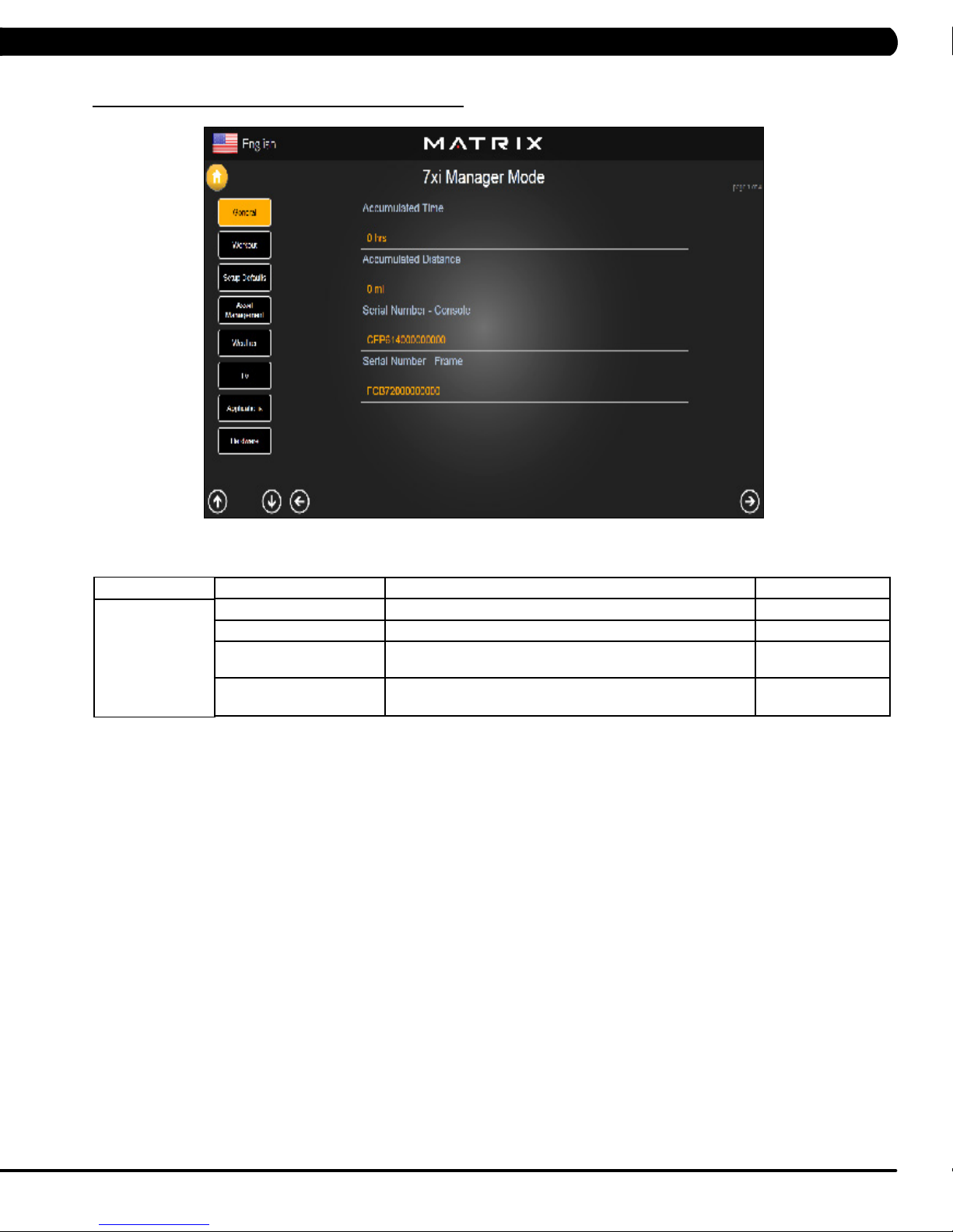
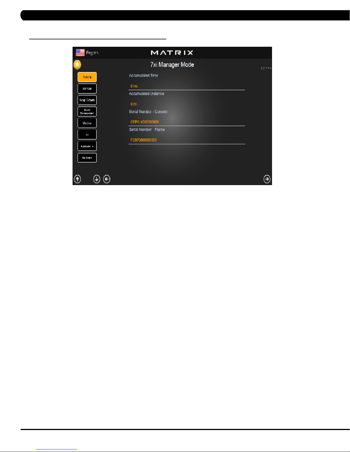
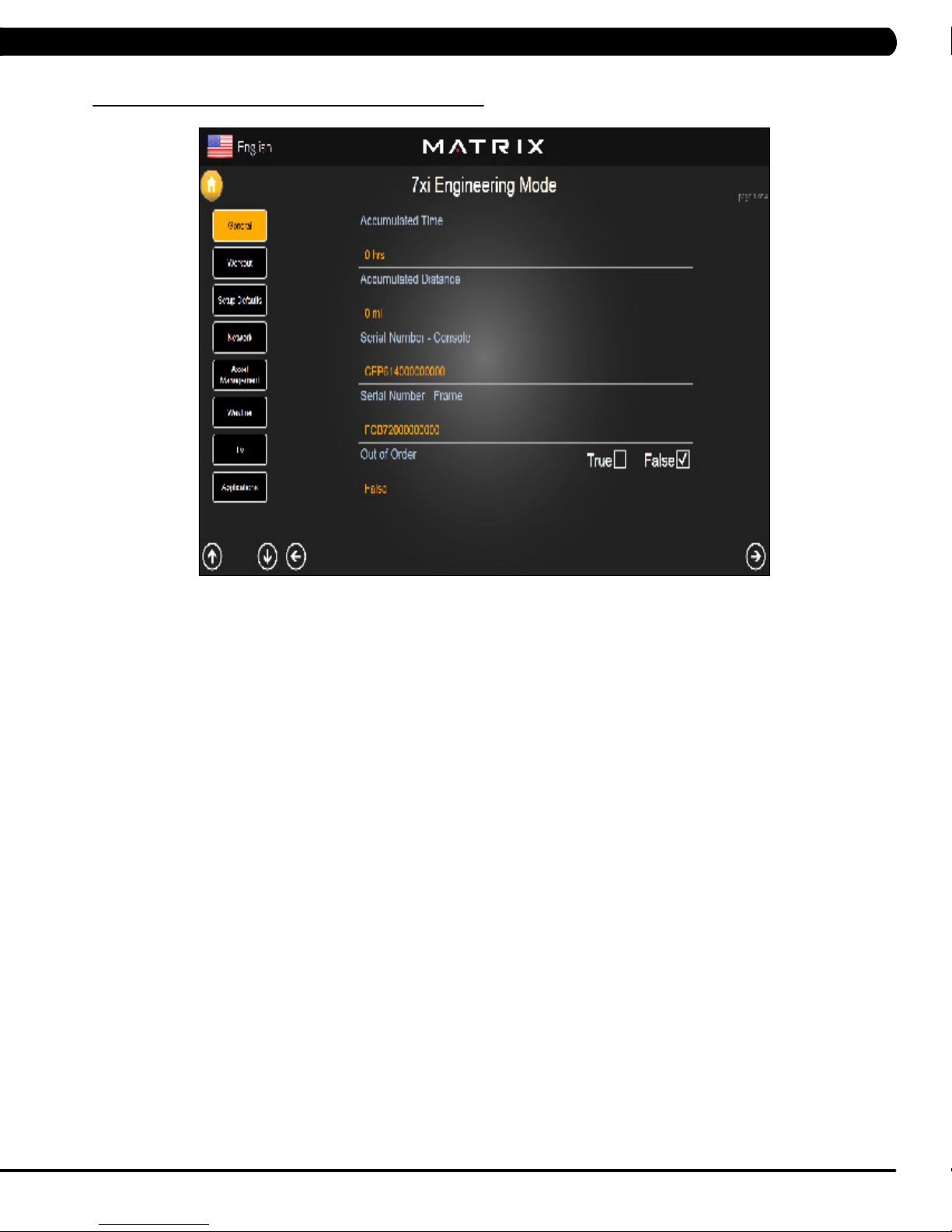
5.2 MANAGER MODE – GENERAL – TAB 1
CHAPTER 5: MANAGER MODE
MANAGER MODE
General
FUNCTION & DEFAULTS DESCRIPTIONS MODIFIED
Accumulated Time Total time on the unit since production. Cannot be modified.
Accumulated Distance Total distance on the unit since production. Cannot be modified.
Serial Number - Console This option displays the serial number of the console, not
editable (see Service Mode to change serial numbers).
Serial Number - Frame This option displays the serial number of the platform, not
editable (see Service Mode to change serial numbers).
Cannot be modified.
Cannot be modified.
11
Page 15
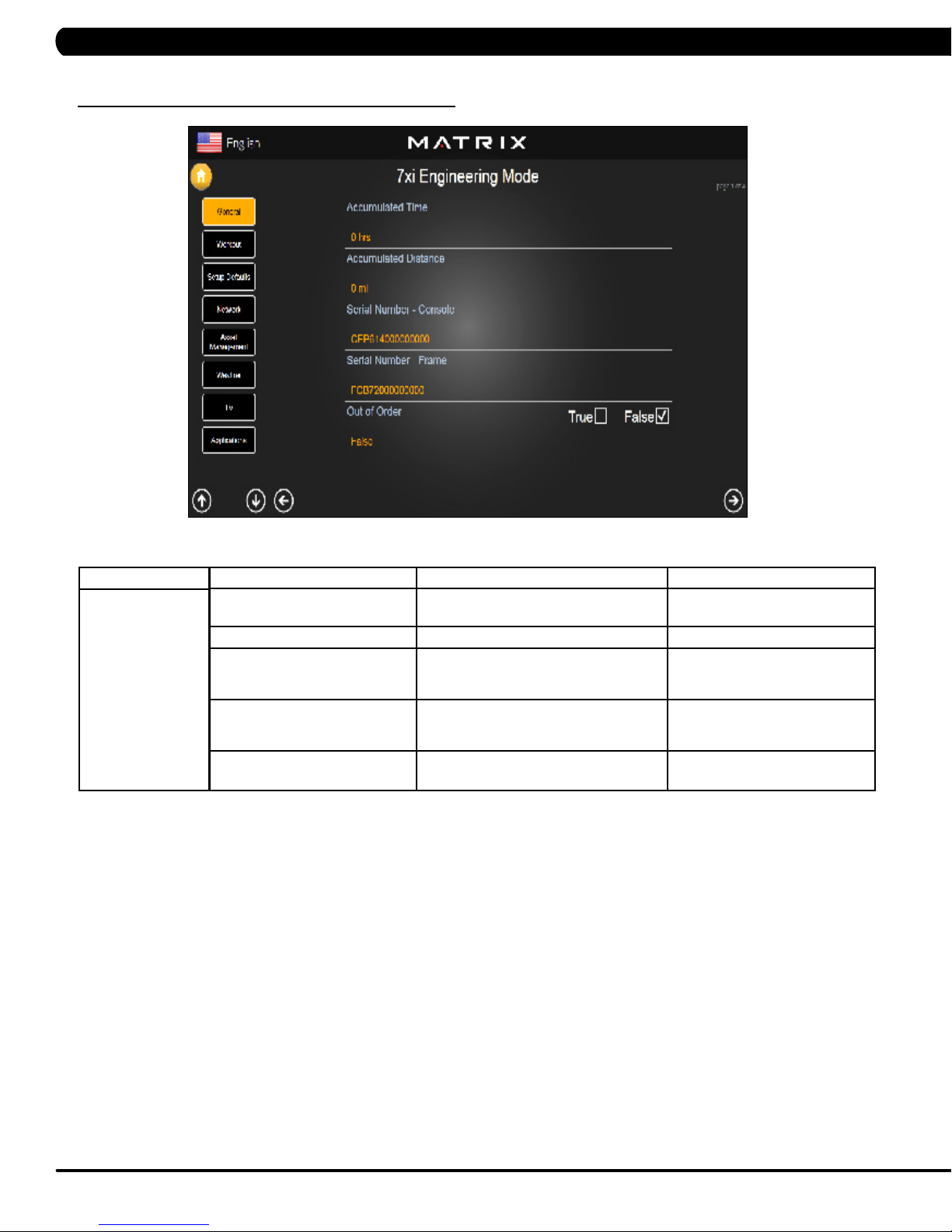
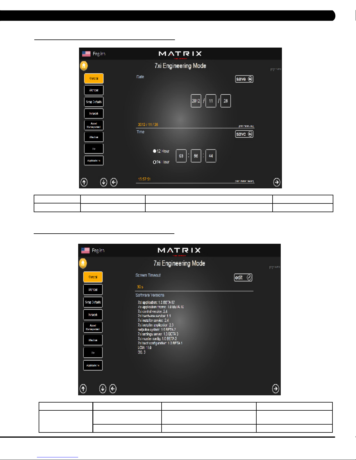
CHAPTER 6: MANAGER MODE
5.2 MANAGER MODE - GENERAL – TAB 2
MANAGER MODE
General
5.2 MANAGER MODE - GENERAL – TAB 3
FUNCTION & DEFAULTS DESCRIPTIONS MODIFIED
Date & Time This option sets the current date and time of the machine. N/A
MANAGER MODE
General
FUNCTION & DEFAULTS DESCRIPTIONS MODIFIED
Screen Timeout This option sets the machine show the
Software Versions Software versions. Cannot be modified.
12
workout time of the machine.
Maximum: 120 sec
Maximum: 15 sec
Page 16
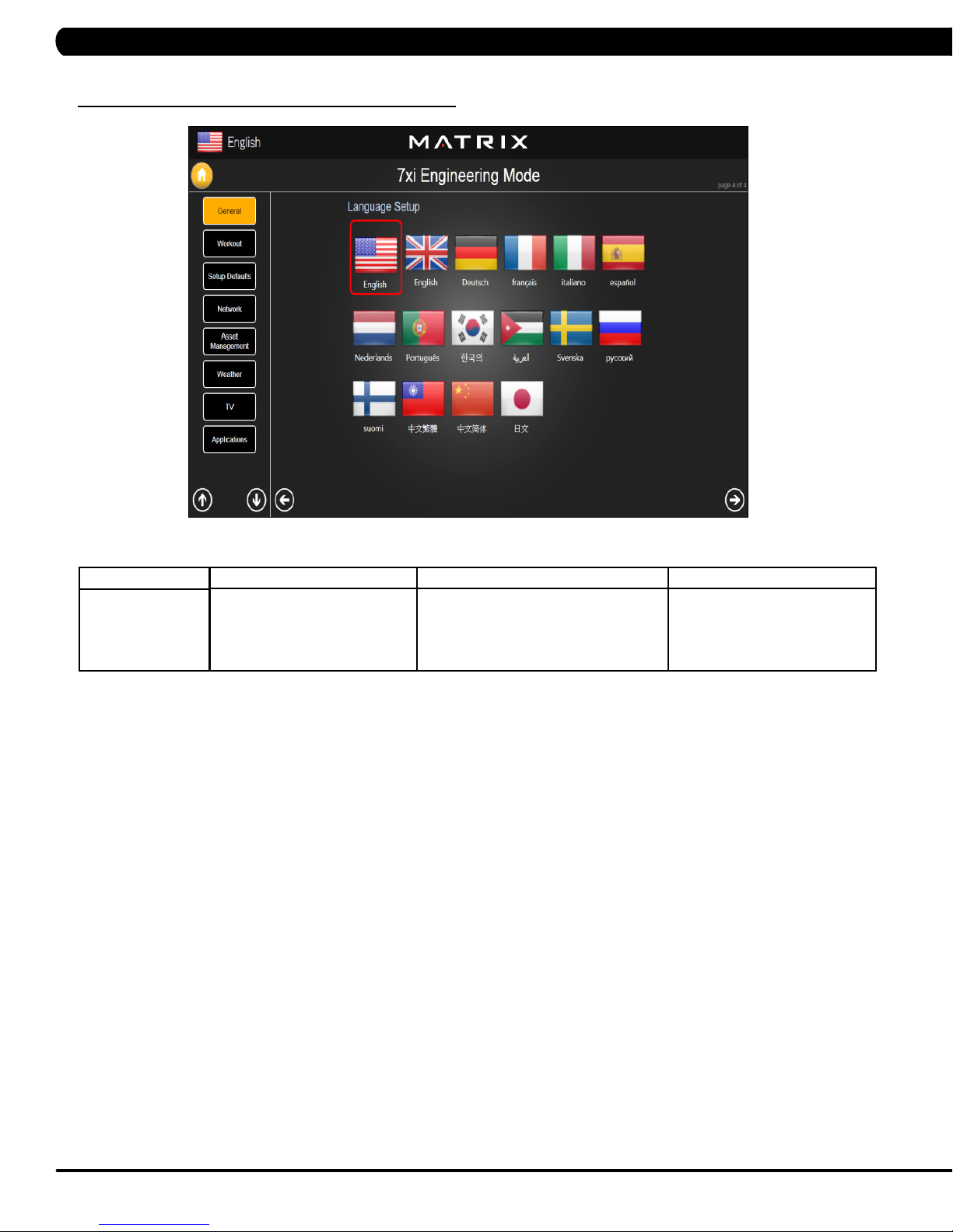
CHAPTER 5: MANAGER MODE
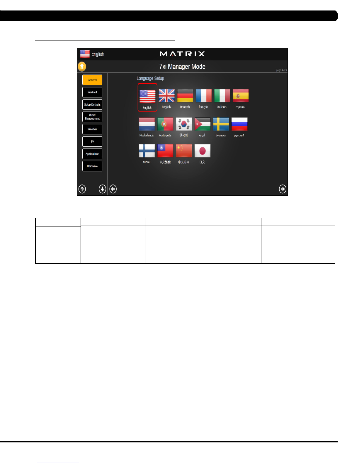
5.2 MANAGER MODE – GENERAL – TAB 4
MANAGER MODE
General
FUNCTION & DEFAULTS DESCRIPTIONS MODIFIED
Language Setup Sets the language used on the console. English (US), English (UK),
German, French, Italian,
Spanish, Dutch, Portuguese,
Korean, Israeli, Swiss, Russian,
Finnish, Taiwanese, Chinese, or
Japanese.
13
Page 17
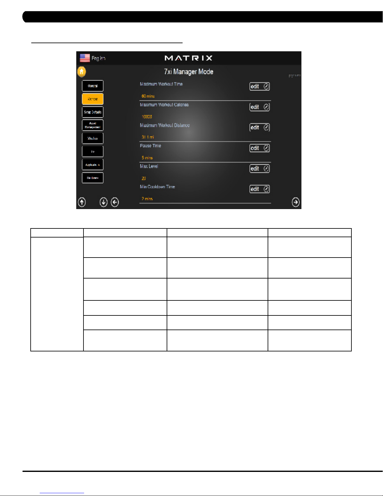
5.3 MANAGER MODE - WORKOUT – TAB 1
CHAPTER 5: MANAGER MODE
MANAGER MODE
Workout
FUNCTION & DEFAULTS DESCRIPTIONS MODIFIED
Maximum Workout Time This option allows the club to set the
maximum workout duration limits during
peak and non peak hours.
Maximum Workout Calories This option allows the club to set the
maximum workout duration limits during
peak and non peak hours.
Maximum Workout Distance This option allows the club to set the
maximum workout duration limits during
peak and non peak hours.
Pause Time This option controls the default pause time. Maximum: 10 Minutes
Max Level This option controls the default program
level.
Min Cooldown Time This option allows the club to set the
minimum cool down duration limits during
peak and non peak hours.
Maximum: 120 Minutes
Minimum: 10 Minutes
Maximum: 10000
Minimum: 50
Maximum: 31.1 mi
Minimum: 0.1 mi
Minimum: 1 Minutes
Maximum: 25
Minimum: 1
Maximum: 5 Minutes
Minimum: 1 Minutes
14
Page 18
CHAPTER 5: MANAGER MODE
5.3 MANAGER MODE - WORKOUT – TAB 2
MANAGER MODE
Workout
FUNCTION & DEFAULTS DESCRIPTIONS MODIFIED
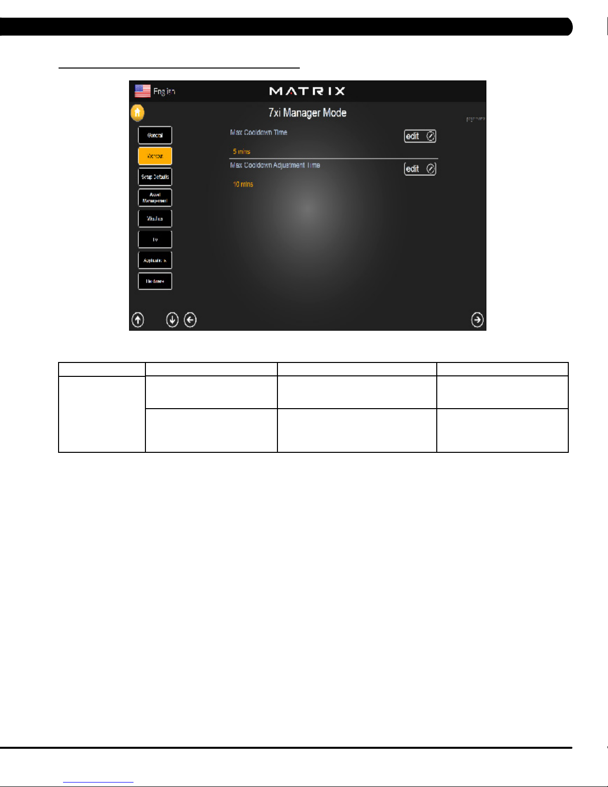
Max Cooldown Time This option allows the club to set the
maximum cool down duration limits during
peak and non peak hours.
Max Cooldown Adjustment Time This option allows the club to set the
maximum cool down adjustment time
duration limits during peak and non peak
hours.
Maximum: 10 Minutes
Minimum: 5 Minutes
Maximum: 20 Minutes
Minimum: 5 Minutes
15
Page 19
CHAPTER 5: MANAGER MODE
5.4 MANAGER MODE - SETUP DEFAULTS – TAB 1
MANAGER MODE
Setup Defaults
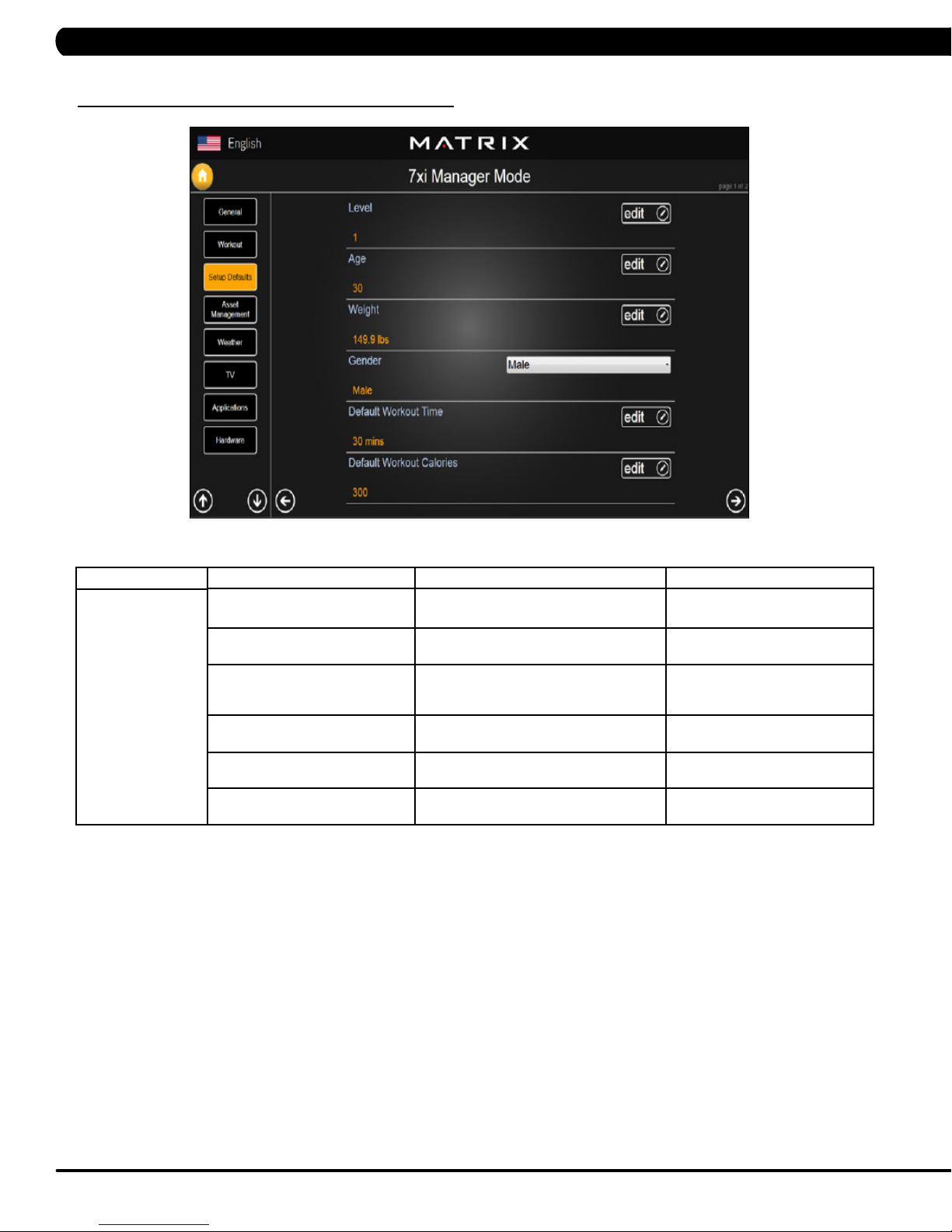
FUNCTION & DEFAULTS DESCRIPTIONS MODIFIED
Level This option controls the default program
levels.
Age This option controls the default user's age
used in the target heart rate calculations.
Weight This option controls the default weight
used in the calorie calculations. Displayed
in native units (pounds or kilograms).
Gender This option sets the user's gender as
either male or female.
Default Workout Time This option controls the default program
time.
Default Workout Calories This option controls the default program
calories.
Maximum: 20
Minimum: 1
Maximum: 99
Minimum: 10
79~401 lbs
Male or Female
Maximum: 60
Minimum: 5
Maximum: 5000
Minimum: 50
16
Page 20
CHAPTER 5: MANAGER MODE
5.4 MANAGER MODE - SETUP DEFAULTS – TAB 2
MANAGER MODE
Setup Defaults
FUNCTION & DEFAULTS DESCRIPTIONS MODIFIED
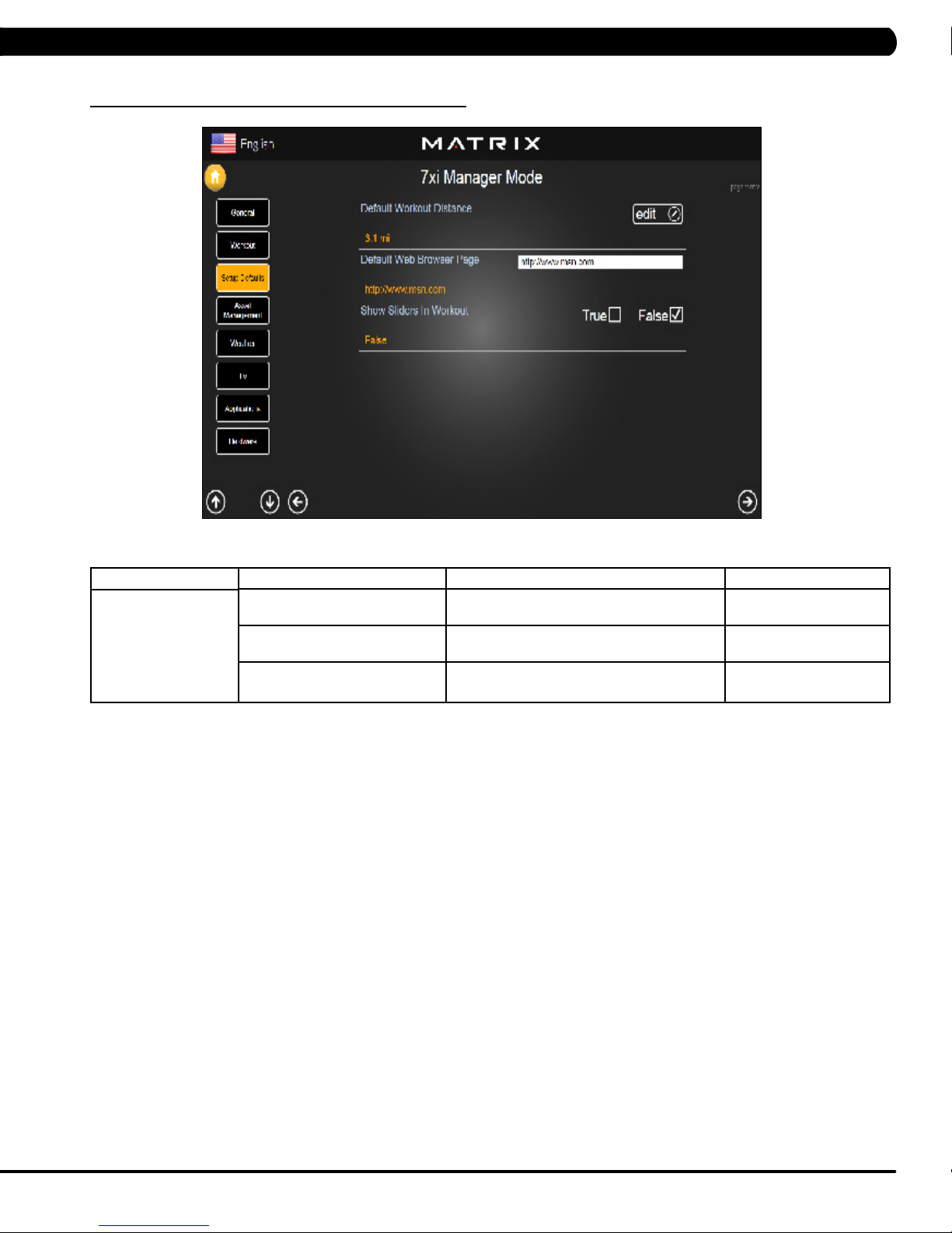
Default Workout Distance This option controls the default program
Distance.
Default Web Brower Page This option controls the default machine Web
Brower Page.
Show Sliders In Workout This option controls the default Sliders bar of
True or False.
Maximum: 12.4
Minimum: 0.1
N/A
True or False
17
Page 21
CHAPTER 5: MANAGER MODE
5.5 MANAGER MODE - ASSET MANAGEMENT
MANAGER MODE
Asset Management
5.6 MANAGER MODE - WEATHER
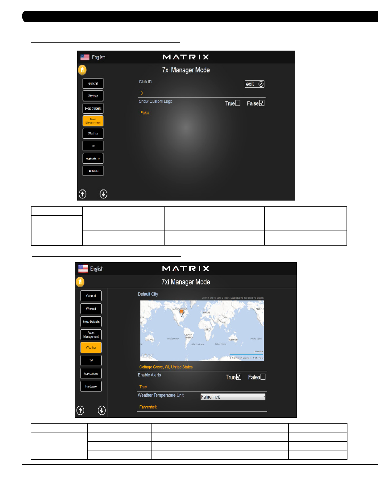
FUNCTION & DEFAULTS DESCRIPTIONS MODIFIED
Club ID This option records the club ID of the
Show Custom Logo This option allows the user to select the
fitness facility.
N/A
True or False
screen Logo from True
MANAGER MODE
Weather
FUNCTION & DEFAULTS DESCRIPTIONS MODIFIED
Default City This option controls the default City Weather. N/A
Enable Alerts This option controls the City Weather function True or False. True or False
Weather Temperature Unit This option controls how temperature is displayed. Fahrenheit or Celsius
18
Page 22
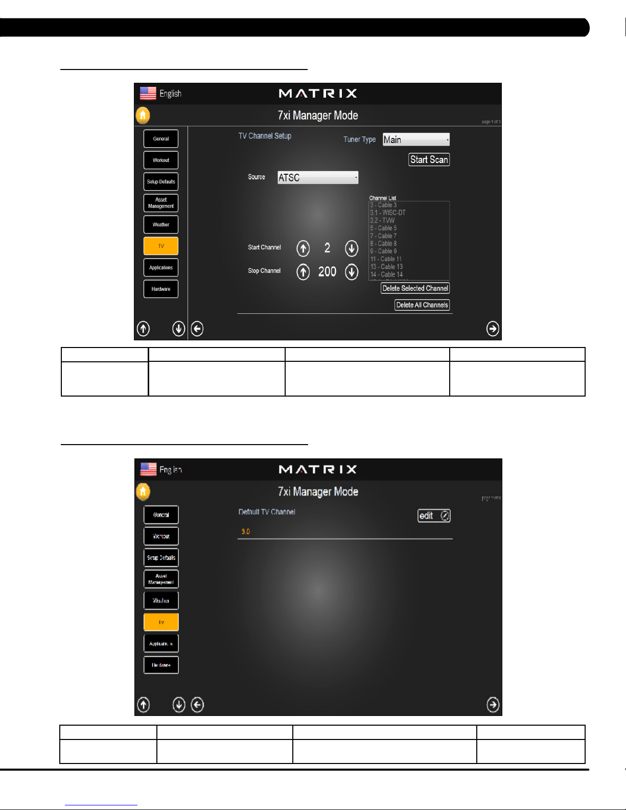
5.7 MANAGER MODE - TV – TAB 1
CHAPTER 5: MANAGER MODE
MANAGER MODE
TV
5.7 MANAGER MODE - TV – TAB 2
FUNCTION & DEFAULTS DESCRIPTIONS MODIFIED
TV Channel Setup This option is for setting the TV tuner
functions. Press the "Start Scan" to search
N/A
the TV Channel.
MANAGER MODE
TV
FUNCTION & DEFAULTS DESCRIPTIONS MODIFIED
Default TV Channel This option controls the default TV channel on
start up.
Maximum: 1000
Minimum: 2
19
Page 23
5.7 MANAGER MODE - TV – TAB 3
CHAPTER 5: MANAGER MODE
MANAGER MODE
TV
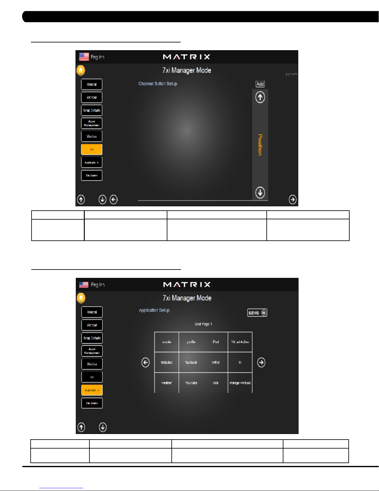
5.8 MANAGER MODE - APPLICATIONS
FUNCTION & DEFAULTS DESCRIPTIONS MODIFIED
Channel Button Setup This option is for setting the TV channel
button. Press the "Add" to edit the channel
N/A
icon, channel name and channel.
MANAGER MODE
Applications
FUNCTION & DEFAULTS DESCRIPTIONS MODIFIED
Application Setup This option is for setting the screen table
20
functions.
N/A
Page 24
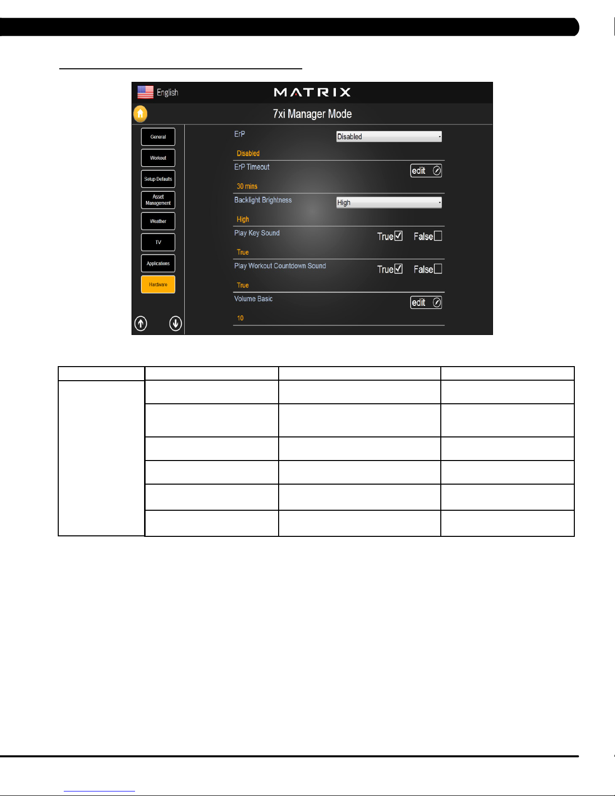
5.9 MANAGER MODE - HARDWARE
CHAPTER 5: MANAGER MODE
MANAGER MODE
Hardware
FUNCTION & DEFAULTS DESCRIPTIONS MODIFIED
ErP This option controls the ErP function is
Disabled or Enabled.
ErP Timeout Amount of time before the console will
enter ErP mode if user does not touch the
screen or press any key.
Backlight Brightness This option controls the screen backlight
Brightness
Play Key Sound This option can set the keypad tone to
sound or not sound.
Play Workout Countdown Sound This option can set the play workout
countdown to sound or not sound.
Volume Basic This option controls the default volume on
start up.
Disabled or Enabled
Maximum: 60
Minimum: 1
Low / Medium / High
True or False
True or False
Maximum: 30
Minimum: 0
21
Page 25
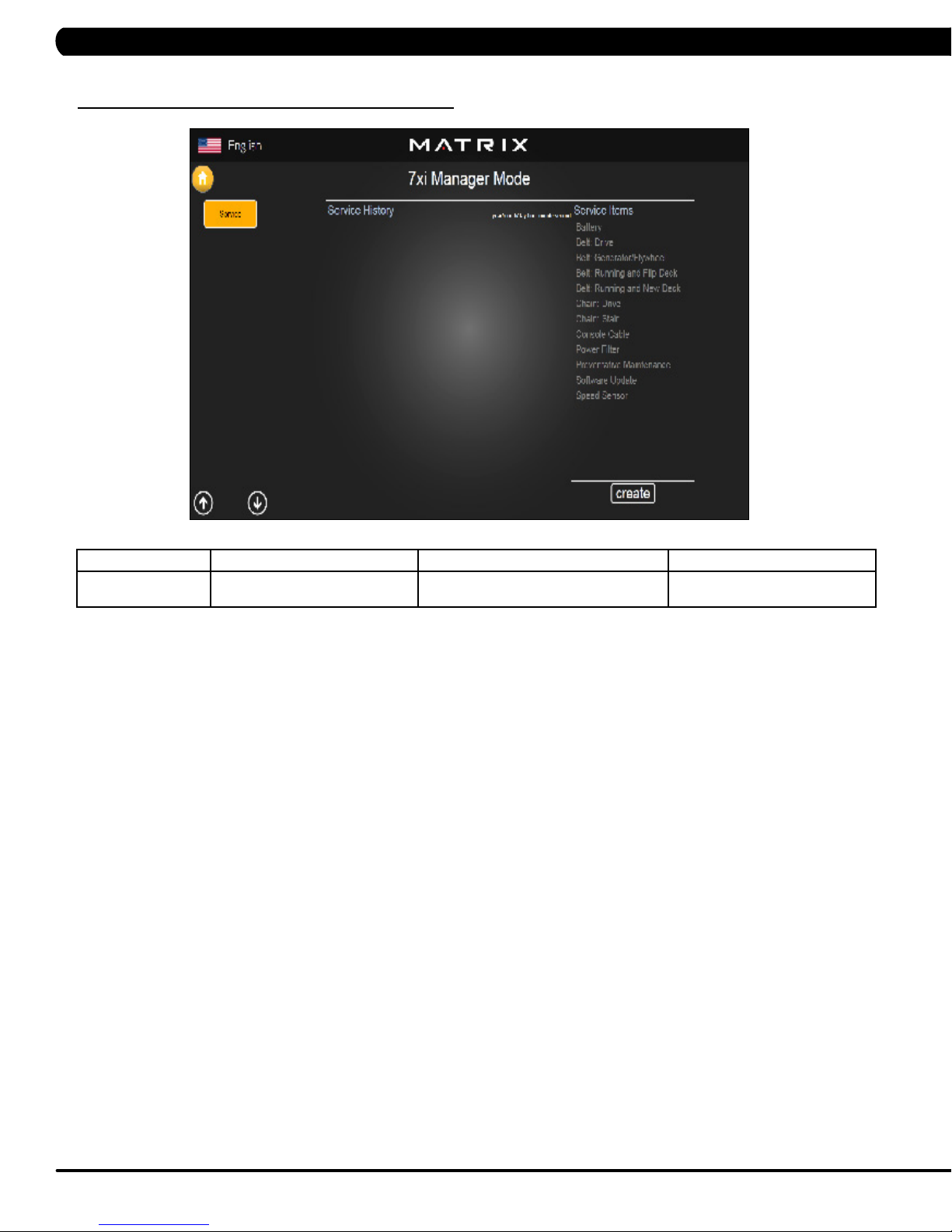
5.10 MANAGER MODE - SERVICE
CHAPTER 5: MANAGER MODE
MANAGER MODE
Service
FUNCTION & DEFAULTS DESCRIPTIONS MODIFIED
Service History This option allows the club to record key
components replacement history.
N/A
22
Page 26
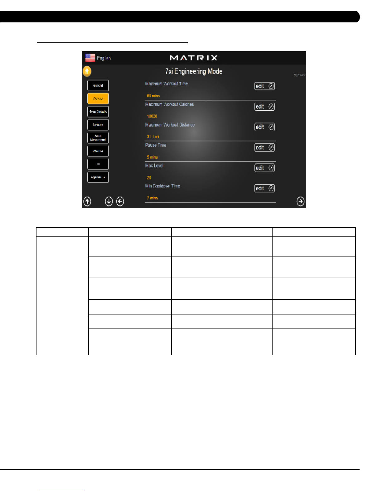
6.1 USING ENGINEERING MODE
CHAPTER 6: ENGINEERING MODE
1) To enter Engineering Mode, press "ENTER, 2, 0, 0, 1, ENTER" on the number keypad and Engineering Mode will appear on the display.
2) Engineering Mode is divided into 12 tabs, located on the left side of the screen. They are General, Workout, Setup Defaults, Network, Asset
Management, Weather, TV, Applications, Calibration, Hardware, Service, Errors.
3) Choose a tab by touching the screen over the desired tab.
4) Each of the tabs has options that will appear once you have chosen that particular tab.
5) Press the "HOME" button or the EMERGENCY STOP to exit Engineering Mode..
23
Page 27
CHAPTER 6: ENGINEERING MODE
6.2 ENGINEERING MODE - GENERAL – TAB 1
MANAGER MODE
General
FUNCTION & DEFAULTS DESCRIPTIONS MODIFIED
Accumulated Time Total time on the unit since production. Cannot be modified.
Accumulated Distance Total distance on the unit since production. Cannot be modified.
Serial Number - Console This option displays the serial number of
the console. See Service Mode to edit the
serial numbers.
Serial Number - Frame This option displays the serial number of
the Frame. See Service Mode to edit the
serial numbers.
Out of Order This option allows the club to show the unit
"out of order" if an error is present.
Cannot be modified.
Cannot be modified.
True / False
24
Page 28
CHAPTER 6: ENGINEERING MODE
6.2 ENGINEERING MODE - GENERAL – TAB 2
MANAGER MODE
General
6.2 ENGINEERING MODE - GENERAL – TAB 3
FUNCTION & DEFAULTS DESCRIPTIONS MODIFIED
Date & Time This option sets the current date and time of the machine. N/A
MANAGER MODE
General
FUNCTION & DEFAULTS DESCRIPTIONS MODIFIED
Screen Timeout This option sets the machine show the
Software Versions Software versions. Cannot be modified.
workout time of the machine.
Maximum: 120 sec
Minimum: 15 sec
25
Page 29
CHAPTER 6: ENGINEERING MODE
6.2 ENGINEERING MODE - GENERAL – TAB 4
MANAGER MODE
General
FUNCTION & DEFAULTS DESCRIPTIONS MODIFIED
Language Setup Sets the language used on the console. English (US), English (UK),
German, French, Italian, Spanish,
Dutch, Portuguese, Korean,
Israeli, Swiss, Russian, Finnish,
Taiwanese, Chinese, or Japanese.
26
Page 30
CHAPTER 6: ENGINEERING MODE
6.3 ENGINEERING MODE - WORKOUT – TAB 1
MANAGER MODE
Workout
FUNCTION & DEFAULTS DESCRIPTIONS MODIFIED
Maximum Workout Time This option allows the club to set the
maximum workout duration limits during
peak and non peak hours.
Maximum Workout Calories This option allows the club to set the
maximum workout duration limits during
peak and non peak hours.
Maximum Workout Distance This option allows the club to set the
maximum workout duration limits during
peak and non peak hours.
Pause Time This option controls the default pause time. Maximum: 10 Minutes
Max Level This option controls the default program
level.
Min Cooldown Time This option allows the club to set the
minimum cool down duration limits during
peak and non peak hours.
Maximum: 120 Minutes
Minimum: 10 Minutes
Maximum: 10000
Minimum: 50
Maximum: 31.1 mi
Minimum: 0.1 mi
Minimum: 1 Minutes
Max: 25
Maximum: 5 Minutes
Minimum: 1 Minutes
27
Page 31

CHAPTER 6: ENGINEERING MODE
6.3 ENGINEERING MODE - WORKOUT – TAB 2
MANAGER MODE
Workout
FUNCTION & DEFAULTS DESCRIPTIONS MODIFIED
Max Cooldown Time This option allows the club to set the
maximum cool down duration limits during
peak and non peak hours.
Max Cooldown Adjustment Time This option allows the club to set the
maximum cool down adjustment time
duration limits during peak and non peak
hours.
Maximum: 10 Minutes
Min: 5 Minutes
Maximum: 20 Minutes
Min: 5 Minutes
28
Page 32

CHAPTER 6: ENGINEERING MODE
6.4 ENGINEERING MODE - SETUP DEFAULTS – TAB 1
MANAGER MODE
Setup Defaults
FUNCTION & DEFAULTS DESCRIPTIONS MODIFIED
Level This option allows the club to set the
maximum workout duration limits during
peak and non peak hours.
Age This option controls the default user's age
used in the target heart rate calculations.
Weight This option controls the default weight
used in the calorie calculations. Displayed
in native units (pounds or kilograms).
Gender This option sets the user's gender as
either male or female.
Default Workout Time This option controls the default program
time.
Default Workout Calories This option controls the default program
calories.
Maximum: 20
Minimum: 1
Maximum: 99
Minimum: 10
79~401 lbs
Male or Female
Maximum: 60
Minimum: 5
Maximum: 5000
Minimum: 50
29
Page 33

CHAPTER 6: ENGINEERING MODE
6.4 ENGINEERING MODE - SETUP DEFAULTS – TAB 2
MANAGER MODE
Setup Defaults
6.5 ENGINEERING MODE - NETWORK – TAB 1
FUNCTION & DEFAULTS DESCRIPTIONS MODIFIED
Default Workout Distance This option controls the default program
Default Web Brower Page This option controls the default machine Web
Show Sliders In Workout This option controls the default Sliders bar of
Distance.
Brower Page.
True or False.
Maximum: 12.4
Minimum: 0.1
N/A
True or False
MANAGER MODE
Network
FUNCTION & DEFAULTS DESCRIPTIONS MODIFIED
Wireless or Wired Network Setup Wifi setting N/A
30
Page 34

CHAPTER 6: ENGINEERING MODE
6.5 ENGINEERING MODE - NETWORK – TAB 2
MANAGER MODE
Network
6.6 ENGINEERING MODE - ASSET MANAGEMENT
FUNCTION & DEFAULTS DESCRIPTIONS MODIFIED
Wireless Network Setup Wifi setting N/A
MANAGER MODE
Asset Management
FUNCTION & DEFAULTS DESCRIPTIONS MODIFIED
Club ID This option records the club ID of the
Show Custom Logo This option allows the user to select the
fitness facility.
N/A
True or False
screen Logo from True.
31
Page 35

6.7 ENGINEERING MODE - WEATHER
CHAPTER 6: ENGINEERING MODE
MANAGER MODE
Weather
6.8 ENGINEERING MODE - TV – TAB 1
FUNCTION & DEFAULTS DESCRIPTIONS MODIFIED
Default City This option controls the default City Weather . N/A
Enable Alerts This option controls the City Weather function True or False. True or False
Weather Temperature Unit This option controls how temperature is displayed. Fahrenheit or Celsius
MANAGER MODE
TV
FUNCTION & DEFAULTS DESCRIPTIONS MODIFIED
TV Channel Setup This option is for setting the TV tuner functions. Press the
32
"Start Scan" to search the TV Channel.
N/A
Page 36

6.8 ENGINEERING MODE - TV – TAB 2
CHAPTER 5: ENGINEERING MODE
MANAGER MODE
TV
6.8 ENGINEERING MODE - TV – TAB 3
FUNCTION & DEFAULTS DESCRIPTIONS MODIFIED
Default TV Channel This option controls the default TV channel
on start up.
Maximum: 1000
Minimum: 2
MANAGER MODE
TV
FUNCTION & DEFAULTS DESCRIPTIONS MODIFIED
Channel Button Setup This option is for setting the TV channel button.
Press the "Add" to edit the channel icon,
N/A
channel name and channel.
33
Page 37

CHAPTER 6: ENGINEERING MODE
6.9 ENGINEERING MODE - APPLICATIONS
MANAGER MODE
Applications
FUNCTION & DEFAULTS DESCRIPTIONS MODIFIED
Application Setup This option is for setting the screen table
functions.
N/A
34
Page 38

CHAPTER 6: ENGINEERING MODE
6.10 ENGINEERING MODE - HARDWARE
MANAGER MODE
Hardware
FUNCTION & DEFAULTS DESCRIPTIONS MODIFIED
ErP This option controls the ErP function is
Disabled or Enabled.
ErP Timeout Console will enter ErP mode if user does
not touch the screen or press any key pad
for couple minutes.
Backlight Brightness This option controls the screen backlight
Brightness
Play Key Sound This option can set the keypad tone to
sound or not sound.
Play Workout Countdown Sound This option can set the play workout
countdown to sound or not sound.
Volume Basic This option controls the default volume on
start up.
Disabled or Enabled
Maximum: 60
Minimum: 1
Low / Medium / High
True or False
True or False
Maximum: 30
Minimum: 0
35
Page 39

6.11 ENGINEERING MODE - SERVICE
CHAPTER 6: ENGINEERING MODE
MANAGER MODE
Service
6.12 ENGINEERING MODE - ERRORS
FUNCTION & DEFAULTS DESCRIPTIONS MODIFIED
Service History This option allows the club to record key
components replacement history.
N/A
MANAGER MODE
Errors
FUNCTION & DEFAULTS DESCRIPTIONS MODIFIED
Error Code History This option displays the error code history on
36
the treadmill.
N/A
Page 40

7.1 USING SERVICE MODE
CHAPTER 7: SERVICE MODE
1) To enter Service Mode, press "ENTER 3, 0, 0, 1, ENTER" on the number keypad and Service Mode will appear on the display.
2) Service Mode is divided into 15 tabs, located on the left side of the screen. They are General, Workout, Setup Defaults, Update, Network,
Asset Management, Weather, TV, Applications, Calibration, Hardware, Virtual Active, Management, Service, Errors.
3) Choose a tab by touching the screen over the desired tab.
4) Each of the tabs has options that will appear once you have chosen that particular tab.
5) Press the "HOME" button or the EMERGENCY STOP to exit Service Mode..
37
Page 41

7.2 SERVICE MODE - GENERAL - TAB 1
CHAPTER 7: SERVICE MODE
MANAGER MODE
General
FUNCTION & DEFAULTS DESCRIPTIONS MODIFIED
Accumulated Time Total time on the unit since production. Cannot be modified.
Accumulated Distance Total distance on the unit since production. Cannot be modified.
Serial Number - Console This option displays the serial number of
the console. See Service Mode to edit the
serial numbers.
Serial Number - Frame This option displays the serial number of
the Frame. See Service Mode to edit the
serial numbers.
Demo Mode This option allows the engineer to try and
errors for console
Out of Order This option allows the club to show the unit
"out of order" if an error is present.
Cannot be modified.
Cannot be modified.
True / False
True / False
38
Page 42

SERVICE MODE - GENERAL – TAB 2
7.2
CHAPTER 7: SERVICE MODE
MANAGER MODE
General
SERVICE MODE - GENERAL – TAB 3
7.2
FUNCTION & DEFAULTS DESCRIPTIONS MODIFIED
Date & Time This option sets the current date and time of the machine. N/A
MANAGER MODE
General
FUNCTION & DEFAULTS DESCRIPTIONS MODIFIED
Screen Timeout This option sets the machine show the
Software Versions Software versions. Cannot be modified.
workout time of the machine.
Maximum: 120 sec
Minimum: 15 sec
39
Page 43

7.2 SERVICE MODE - GENERAL - TAB 4
CHAPTER 7: SERVICE MODE
MANAGER MODE
General
FUNCTION & DEFAULTS DESCRIPTIONS MODIFIED
Language Setup Sets the language used on the console. English (US), English (UK),
German, French, Italian, Spanish,
Dutch, Portuguese, Korean,
Israeli, Swiss, Russian, Finnish,
Taiwanese, Chinese, or Japanese.
40
Page 44

7.3 SERVICE MODE - WORKOUT – TAB 1
CHAPTER 7: SERVICE MODE
MANAGER MODE
Workout
FUNCTION & DEFAULTS DESCRIPTIONS MODIFIED
Maximum Workout Time This option allows the club to set the
maximum workout duration limits during
peak and non peak hours.
Maximum Workout Calories This option allows the club to set the
maximum workout duration limits during
peak and non peak hours.
Maximum Workout Distance This option allows the club to set the
maximum workout duration limits during
peak and non peak hours.
Pause Time This option controls the default pause time. Maximum: 10 Minutes
Max Level This option controls the default program
level.
Min Cooldown Time This option allows the club to set the
minimum cool down duration limits during
peak and non peak hours.
Maximum: 120 Minutes
Minimum: 10 Minutes
Maximum: 10000
Minimum: 50
Maximum: 31.1 mi
Minimum: 0.1 mi
Minimum: 1 Minutes
Maximum: 25
Minimum: 1
Maximum: 5 Minutes
Minimum: 1 Minutes
41
Page 45

7.3 SERVICE MODE - WORKOUT – TAB 2
CHAPTER 7: SERVICE MODE
MANAGER MODE
Workout
FUNCTION & DEFAULTS DESCRIPTIONS MODIFIED
Max Cooldown Time This option allows the club to set the
maximum cool down duration limits during
peak and non peak hours.
Max Cooldown Adjustment Time This option allows the club to set the
maximum cool down adjustment time
duration limits during peak and non peak
hours.
Maximum: 10 Minutes
Minimum: 5 Minutes
Maximum: 20 Minutes
Minimum: 5 Minutes
42
Page 46

CHAPTER 7: SERVICE MODE
7.4 SERVICE MODE - SETUP DEFAULTS – TAB 1
MANAGER MODE
Setup Defaults
FUNCTION & DEFAULTS DESCRIPTIONS MODIFIED
Level This option controls the default program
levels.
Age This option controls the default user's age
used in the target heart rate calculations.
Weight This option controls the default weight
used in the calorie calculations. Displayed
in native units (pounds or kilograms).
Gender This option sets the user's gender as
either male or female.
Default Workout Time This option controls the default program
time.
Default Workout Calories This option controls the default program
calories.
Maximum: 20
Minimum: 1
Maximum: 99
Minimum: 10
79~401 lbs
Male or Female
Maximum: 60
Minimum: 5
Maximum: 5000
Minimum: 50
43
Page 47

CHAPTER 7: SERVICE MODE
7.4 SERVICE MODE - SETUP DEFAULTS – TAB 2
MANAGER MODE
Setup Defaults
7.5 SERVICE MODE - UPDATE
Default Workout Distance This option controls the default program
Default Web Brower Page This option controls the default machine Web
Show Sliders In Workout This option controls the default Sliders bar of
FUNCTION & DEFAULTS DESCRIPTIONS MODIFIED
Distance
Brower Page
True or False
Maximum: 12.4
Minimum: 0.1
N/A
True or False
MANAGER MODE
Update
FUNCTION & DEFAULTS DESCRIPTIONS MODIFIED
Check For Updates At boot Wifi setting N/A
Automatic Update Software update automatic
44
N/A
Page 48

7.6 SERVICE MODE - NETWORK – TAB 1
CHAPTER 7: SERVICE MODE
MANAGER MODE
Network
7.6 SERVICE MODE - NETWORK – TAB 2
FUNCTION & DEFAULTS DESCRIPTIONS MODIFIED
Wireless or Wired Network Setup Wifi setting N/A
MANAGER MODE
Network
FUNCTION & DEFAULTS DESCRIPTIONS MODIFIED
Wireless Network Setup Wifi setting N/A
45
Page 49

CHAPTER 7: SERVICE MODE
7.7 SERVICE MODE - ASSET MANAGEMENT
MANAGER MODE
Asset Management
7.8 SERVICE MODE - WEATHER
FUNCTION & DEFAULTS DESCRIPTIONS MODIFIED
Club ID This option records the club ID of the
Show Custom Logo This option allows the user to select the
fitness facility.
N/A
True or False
screen Logo from True
MANAGER MODE
Weather
FUNCTION & DEFAULTS DESCRIPTIONS MODIFIED
Default City This option controls the default City Weather . N/A
Enable Alerts This option controls the City Weather function True or False. True or False
Weather Temperature Unit This option controls how temperature is displayed. Fahrenheit or Celsius
46
Page 50

7.9 SERVICE MODE - TV – TAB 1
CHAPTER 7: SERVICE MODE
MANAGER MODE
TV
7.9 SERVICE MODE - TV – TAB 2
FUNCTION & DEFAULTS DESCRIPTIONS MODIFIED
TV Channel Setup This option is for setting the TV tuner functions. Press the
"Start Scan" to search the TV Channel.
N/A
MANAGER MODE
TV
FUNCTION & DEFAULTS DESCRIPTIONS MODIFIED
Default TV Channel This option controls the default TV channel
on start up.
Maximum: 1000
Minimum: 2
47
Page 51

7.9 SERVICE MODE - TV – TAB 3
CHAPTER 7: SERVICE MODE
MANAGER MODE
TV
7.10 SERVICE MODE - APPLICATIONS
FUNCTION & DEFAULTS DESCRIPTIONS MODIFIED
Channel Button Setup This option is for setting the TV channel button.
Press the "Add" to edit the channel icon,
N/A
channel name and channel.
MANAGER MODE
Applications
FUNCTION & DEFAULTS DESCRIPTIONS MODIFIED
Application Setup This option is for setting the screen table
48
functions.
N/A
Page 52

7.11 SERVICE MODE - HARDWARE – TAB 1
CHAPTER 7: SERVICE MODE
MANAGER MODE
Hardware
FUNCTION & DEFAULTS DESCRIPTIONS MODIFIED
ErP This option controls the ErP function is
Disabled or Enabled.
ErP Timeout Amount of time before the screen goes
into ERP mode if the user does not touch
a key or the screen.
Backlight Brightness This option controls the screen backlight
Brightness
LCM test Write test pattern N/A
Small LCD Reversed This option can set the small LCD to
reversed.
Play Key Sound This option can set the keypad tone to
sound or not sound.
Disabled or Enabled
Maximum: 60
Minimum: 1
Low / Medium / High
True or False
True or False
49
Page 53

7.11 SERVICE MODE - HARDWARE – TAB 2
CHAPTER 7: SERVICE MODE
MANAGER MODE
Hardware
FUNCTION & DEFAULTS DESCRIPTIONS MODIFIED
Play Workout Countdown Sound This option can set the play workout
countdown to sound or not sound.
Volume Basic This option controls the default volume on
start up.
Volume Advanced This option controls the default volume on
start up for Master, iPod, Virtual Active,
CSAFE, TV, Media Player
True or False
Maximum: 30
Minimum: 0
N/A
50
Page 54

7.12 SERVICE MODE - VIRTUAL ACTIVE
CHAPTER 7: SERVICE MODE
MANAGER MODE
Virtual Active
7.13 SERVICE MODE - MANAGEMENT
FUNCTION & DEFAULTS DESCRIPTIONS MODIFIED
Root Path This Virtual Active root path setting D:
MANAGER MODE
Management
FUNCTION & DEFAULTS DESCRIPTIONS MODIFIED
Setting Manager Setting Manager date N/A
51
Page 55

7.14 SERVICE MODE - SERVICE
CHAPTER 7: SERVICE MODE
MANAGER MODE
Service
7.15 SERVICE MODE - ERRORS
FUNCTION & DEFAULTS DESCRIPTIONS MODIFIED
Service History This option allows the club to record key
components replacement history.
N/A
MANAGER MODE
Errors
FUNCTION & DEFAULTS DESCRIPTIONS MODIFIED
Error Code History This option displays the error code history on
52
the treadmill.
N/A
Page 56

7.16 SERVICE MODE - NETPULSE
CHAPTER 7: SERVICE MODE
MANAGER MODE
Netpulse
FUNCTION & DEFAULTS DESCRIPTIONS MODIFIED
Test network and netpulse install. N/A
53
Page 57

CHAPTER 7: SERVICE MODE
7.17 MATRIX FITNESS 7XI SERIES FEATURE ACCESS CODES
This document defines the supported feature access codes for the Matrix Fitness 7xi series fitness equipment.
Instruction
All codes are entered in by:
1. Press the “Enter” key.
2. Press the series of numbers in the code.
3. Press the “Enter” key.
CODE DESCRIPTION
1001
2001
3001
3002
3004
3008
4001
4002
4004
4005
4006
732668
7944357
62728466
287767
999
Enter manager screen.
Enter engineering screen.
Enter service screen
Model selection
Update manager
Enable/disable all errors
Take a screen shot of the current screen
Show/hide the system resources window
Show/hide CSAFE log window
Set factory defaults
Export the error logs to an external USB drive
Reboot
Show help window
Marathon mode
Show/hide cursor
Record workout data to USB drive at summary screen (INTERNAL USE ONLY)
54
Page 58

8.1 ELECTRICAL DIAGRAMS
CHAPTER 8: TROUBLESHOOTING
55
Page 59

CHAPTER 8: TROUBLESHOOTING
8.1 ELECTRICAL DIAGRAMS - CONTINUED
56
Page 60

8.1 ELECTRICAL DIAGRAMS - CONTINUED
PULSE SENSOR WIRE
CHAPTER 8: TROUBLESHOOTING
POWER RESISTANCE WIRE
57
Page 61

8.1 ELECTRICAL DIAGRAMS - CONTINUED
DIGITAL COMMUNICATION WIRE
CHAPTER 8: TROUBLESHOOTING
ECB WIRE
58
Page 62

8.2 LCB LED INDICATORS
CHAPTER 8: TROUBLESHOOTING
====================== FIRMWARE DEFINITION ========================
LED6: LCB STATUS (BLINKING: OK)
LED7: RESISTANCE REGULATE STATUS (BRIGHT : NORMAL )
LED8: UCB/LCB COMMUNICATION STATUS (BLINKING : OK )
====================== HARDWARE DEFINITION =======================
LED1: AC PLUG-IN STATUS (BRIGHT : AC )
LED2: DC 5V STATUS (BRIGHT : OK)
LED3: AC PLUG-IN STATUS (BRIGHT : AC )
LED4: DC 12V STATUS (BRIGHT : OK )
LED5: RPM
LED9: UCB POWER SUPPLY STATUS (BRIGHT: POWER ON)
LED10: RESISTANCE PWM STATUS (BRIGHT: RESISTANCE ON)
59
Page 63

8.3
LCB WIRING CONNECTIONS
CHAPTER 8: TROUBLESHOOTING
60
Page 64

CHAPTER 8: TROUBLESHOOTING
8.4 TROUBLESHOOTING - ERROR 04A0
ERROR CODE 04A0
1) SYMPTOM:
04A0 – UCB communication disconnected.
2) SOLUTION:
1) Check the connection of the console cable at the UCB and LCB. Also check the console cable for damage, replace as needed.
2) If the console cable connections are good, the issue is likely with the UCB. Replace the UCB.
FIGURE A FIGURE B
61
Page 65

CHAPTER 8: TROUBLESHOOTING
8.5 TROUBLESHOOTING - ERROR 04B0
ERROR CODE 04B0
1) SYMPTOM:
04B0 – LCB communication disconnected.
2) SOLUTION:
1) Check the connection of the console cable at the UCB and LCB. Also check the console cable for damage, replace as needed.
2) If the console cable connections are good, the issue is likely with the LCB. Replace the LCB.
FIGURE A FIGURE B
62
Page 66

CHAPTER 8: TROUBLESHOOTING
8.6 TROUBLESHOOTING - ERROR 0248
ERROR CODE 0248
1) SYMPTOM:
0248 - Battery disconnection or fail. (When power is on, LCB battery voltage is less than 6 VAC).
2) SOLUTION:
1) Check the battery wire connection between the battery and LCB (Figure A).
2) Check the battery voltage (Figure B), if it is less than 6 VAC, replace the battery.
3) If the battery voltage is more than 6 VAC, replace the LCB.
FIGURE A FIGURE B
63
Page 67

CHAPTER 8: TROUBLESHOOTING
8.7 TROUBLESHOOTING - ERROR 02B4
ERROR CODE 02B4
1) SYMPTOM:
02B4 – Resistance type error.
2) SOLUTION:
1) Check if the machine has the correct resistance system (resistor or ECB) (Figures A & B).
2) Check if the console is matched with the correct frame, and that the Machine Type is set correctly in Engineering Mode.
3) Replace the LCB.
4)..Replace the UCB. .
ECB use on SC5x frame and EP84 (ECB system E5x).Resistor use on HUREA5x frame
FIGURE A FIGURE B
64
Page 68

CHAPTER 8: TROUBLESHOOTING
8.8 TROUBLESHOOTING - ERROR 02AB
ERROR CODE 02AB
1) SYMPTOM:
02AB - Machine type error.
2) SOLUTION:
1) Enter Manager Mode and verify that the Machine Type setting is correct (Figure A).
- If not correct, press ENTER, 3, 0, 0, 2, ENTER on the lower keypad and select the correct Machine Type (Figure B).
FIGURE A FIGURE B
65
Page 69

CHAPTER 8: TROUBLESHOOTING
8.9 TROUBLESHOOTING - ERROR 01AC
ERROR CODE 01AC
1) SYMPTOM:
01AC - Resistance over current
2) SOLUTION:
1) Check the resistance coming out of the resistor (Figure A).
- If the resistance value is under 8 ohms, replace the power resistance.
- If the resistance value is over 8 ohms, replace the LCB.
FIGURE A
66
Page 70

CHAPTER 8: TROUBLESHOOTING
8.10 TROUBLESHOOTING - NO RESISTANCE ISSUES
NO RESISTANCE TROUBLESHOOTING
1) SYMPTOM:
No resistance
2) SOLUTION:
1) Check the power resistor wire connection between the power resistor and the LCB (Figure A).
2) Check if there is a resistance value by measuring amperage through the generator cable (Figure A).
- If there is not a resistance value, replace the resistor.
- If there is a resistance value, replace the LCB.
FIGURE A FIGURE BFIGURE A FIGURE B
67
Page 71

CHAPTER 8: TROUBLESHOOTING
8.11 TROUBLESHOOTING - HEART RATE ISSUES
HEART RATE FUNCTION DOES NOT WORK OR IS READING INCORRECTLY
POSSIBLE CAUSES:
1) The HR grips are not hooked up correctly.
2) The HR grip wiring is damaged.
3) The console or HR board is not properly grounded.
4) The console, HR board, or wiring between are bad.
SOLUTION:
1) Perform a DC Voltage test on the HR grips.
a. With one prong of a multi meter on each of the plates on one side of the HR grip set (Figure A), a voltage reading of between .5 and 2.0
should be seen. If the reading is correct, the issue is not with the HR grips or grip wiring.
b. If the reading is not correct, remove the screws holding the halves of the HR grip together and check the connection of the wiring to the
grips (Figure B).
2) Remove the console from the unit and verify continuity of the HR grip wiring. With a multi meter set for ohms, place one prong on the HR grip
wiring coming up the console mast (Figure C), and the other on the appropriate plate (match red with red and white with white).
a. An ohm reading of less than 1 should be received. If it is higher, replace the HR grip wiring.
3) Perform a continuity check on the console (See Service Bulletin - Continuity Test on Matrix Bikes).
a. Once the console continuity is confirmed, perform a continuity check on the HR board ground wire. With a multi meter set for ohms, place
one prong on the HR board ground wire (Figure D), and the other on the console ground wire. An ohm reading of less than 1 should be received.
If it is higher, replace the HR board.
4) If all the troubleshooting listed above has been performed, and the unit still has HR issues, replace the HR board.
a. If the HR board does not resolve the issue, replace the console.
FIGURE A
FIGURE B
FIGURE C
68
FIGURE D
Page 72

CHAPTER 8: TROUBLESHOOTING
8.12 TV TROUBLESHOOTING - OVERVIEW
Sections 8.12 - 8.15 will assist with diagnosing problems with TV and entertainment related equipment sold
by Matrix FItness Equipment.
The Matrix Bike includes an integrated TV that shows in the large display window. The TV is capable of being shown as a 9" or 12" screen
(Figures A & B). The console should be equipped with an entertainment keypad similar to Figure C.
FIGURE A
FIGURE B
FIGURE C
69
Page 73

CHAPTER 8: TROUBLESHOOTING
8.13 TV TROUBLESHOOTING - PICTURE FUZZY OR UNCLEAR
1) For a fuzzy or unclear picture, see the TV programming instructions in Section 10. If the TV is still fuzzy or unclear after programming:
a) Check the coax connection at the entertainment port (Figure A).
b) Remove the 5 screws holding the console to the console mast and check the coax connection at the console (Figure B).
FIGURE A
c) Use a verified good piece of coax cable (a good coax cable will have a signal strength of 10db or greater) to plug directly into the back
of the console bypassing the entertainment port. If this resolves the issue, replace the internal coax cable.
d) If plugging the coax cable into the back of the console does not resolve the issue, remove the console back and check the console
cable connection at the tuner (Figure C).
e) Check the internal cables and fitting inside your machine at the console and below the front shroud (Figure D). Make sure you have
no kinks, cuts, or poor connectors at the end of the cable. Fittings should have a clean flush connector with no stray aluminum strands touching
the center conductor. Replace any suspect cables.
FIGURE B
FIGURE C FIGURE D
f) If no damage can be found on the cables, fittings, or connectors, and hooking the coax directly to the back of the console does not
resolve the issue, replace the TV tuner.
70
Page 74

CHAPTER 8: TROUBLESHOOTING
8.14 TV TROUBLESHOOTING - TV WILL NOT TURN ON
1) Remove the console back and check the electrical connections for the TV (Figures A & B).
FIGURE BFIGURE A
2) If internal electrical connections are good (the console turns on), and the outlet is outputting 120V, the issue is likely with the integrated TV.
Replace the console.
FIGURE C
71
Page 75

CHAPTER 8: TROUBLESHOOTING
8.15 TV TROUBLESHOOTING - ENTERTAINMENT KEYPAD ISSUES8.15 TV TROUBLESHOOTING - ENTERTAINMENT KEYPAD ISSUES
ENTERTAINMENT KEYPAD IS NOT WORKING
1) SYMPTOM:
a. The entertainment keypad (Figure A) is not responding.
2) SOLUTION:
a. Remove the console and check the connection of the entertainment keypad (Figure B).
b. If the entertainment keypad cable is pinched, kinked, or cut replace the keypad.
c. If replacing the keypad does not resolve the issue, replace the console.
FIGURE A
FIGURE B
72
Page 76

CHAPTER 9: PART REPLACEMENT GUIDE
9.1 CONSOLE REPLACEMENT
1) Remove the 5 screws holding the console to the frame (Figure A).
FIGURE A
2) Disconnect the console cable and HR connections from the defective console and remove the console (Figure B).
3) Reinstall the wire connections to the new console.
4) Carefully push the wires into the console and mast until they are clear of the console / mast connection and attach the console to the mast
using the 4 screws.
5) Test the bike for function as outlined in Section 9.22.
FIGURE B
73
Page 77

CHAPTER 9: PART REPLACEMENT GUIDE
9.2 HEART RATE HANDLEBAR REPLACEMENT
1) Remove the 2 screws holding on the handlebar cover (Figures A & B).
FIGURE A FIGURE B
2) Remove the 4 screws holding the heart rate handlebar to the console mast being careful to support the handlebar (Figure C).
3) Carefully pull the wires from the console mast until the connectors are showing, and then disconnect the 3 wires from the handlebar and
remove the defective handlebar (Figure D).
FIGURE C FIGURE D
4) Reverse Steps 1-3 to install a new handlebar.
5) Test the bike for function as outlined in Section 9.22.
74
Page 78

CHAPTER 9: PART REPLACEMENT GUIDE
9.3 HEART RATE GRIPS REPLACEMENT
1) Remove the 3 screws holding the 2 halves of the HR grip together (Figure A).
2) Split the HR grip in half (Figure B).
FIGURE A FIGURE B
3) Disconnect the level key and HR plate wiring (Figure C) and remove the HR grip.
4) Reverse Steps 1-3 to install a new HR grip. NOTE: When plugging in the HR plate wiring, the red wire should go to the top plate, the white
wire to the bottom HR plate (Figure D).
FIGURE C
5) Test the Bike for function as outlined in Section 9.22.
FIGURE D
75
Page 79

CHAPTER 9: PART REPLACEMENT GUIDE
9.4 CUP HOLDER REPLACEMENT
1) Remove the 2 screws holding the cup holder to the console mast (Figure A).
FIGURE A
2) Remove the cup holder (Figure B).
3) Reverse Steps 1-2 to install a new cup holder.
FIGURE B
76
Page 80

CHAPTER 9: PART REPLACEMENT GUIDE
9.5 CONSOLE KEYPAD / OVERLAY REPLACEMENT
NOTE: The instructions below are for console overlays / keypads replacement, but the procedure is the same regardless of where the overlay /
keypad is.
1) Remove the console as outlined in Section 9.1.
2) Remove the back cover of the console (Figure A).
3) Unplug and remove the faulty overlay (Figure B).
FIGURE A
4) Clean the console area with alcohol to remove any left over adhesive (Figure C).
5) Peel part of the protective film from the back of the overlay / keypad (Figure D).
FIGURE C FIGURE D
FIGURE B
77
Page 81

CHAPTER 9: PART REPLACEMENT GUIDE
9.5 CONSOLE KEYPAD / OVERLAY REPLACEMENT - CONTINUED
6) Push the overlay / keypad ribbon cable through the hole in the console and plug it in (Figure E).
7) Match the overlay / keypad to the cutout in the console (Figure F).
FIGURE E FIGURE F
8) Press down on the corners of the overlay / keypad to keep it in place. Then remove the protective film (Figure G).
9) Once the overlay / keypad is in the correct position, press down on it to adhere it in positions (Figure H).
FIGURE G FIGURE H
10) Use the same procedure to replace any additional faulty overlays / keypads. NOTE: Overlays / keypads cannot be re-used.
11) Test the bike for function as outlined in Section 9.22.
78
Page 82

CHAPTER 9: PART REPLACEMENT GUIDE
9.6 CONSOLE MAST REMOVAL
1) Remove the console as outlined in Section 9.1.
2) Remove the HR handlebars as outlined in Section 9.2.
3) Lift up the rubber boot at the bottom of the console mast (Figure A).
FIGURE A
4) With the boot lifted, remove the 4 screws holding the console mast to the frame (Figure B).
FIGURE B
5) Pull the wires out the bottom of the console mast and remove the mast.
6) Reverse Steps 1-5 to install a new console mast. NOTE: When installing a new console mast, be sure to pull the console wires up through
the new mast prior to installing the 4 screws into the frame.
7) Test the bike for function as outlined in Section 9.22.
79
Page 83

CHAPTER 9: PART REPLACEMENT GUIDE
9.7 SEAT PAD REPLACEMENT
1) Remove the 4 screws holding the seat pad to the seat post (Figure A).
FIGURE A
2) Lift the seat pad away from the seat post (Figure B).
3) Reverse Steps 1-2 to install a new seat pad.
FIGURE B
80
Page 84

CHAPTER 9: PART REPLACEMENT GUIDE
9.8 BACK PAD REPLACEMENT
1) Using the tips of your fingers, remove the back cover of the back pad. The back cover is held on by plastic snap clips, and if pressure is
applied, the cover will pop off (Figure A).
2) Remove the 4 bolts holding the seat pad to the seat frame (Figure B).
FIGURE A
3) Remove the back pad (Figure C).
4) Reverse Steps 1-3 to install a new back pad.
FIGURE B
FIGURE C
81
Page 85

CHAPTER 9: PART REPLACEMENT GUIDE
9.9 STATIONARY HANDLEBAR REPLACEMENT
1) Using the tips of your fingers, remove the back cover of the back pad. The back cover is held on by plastic snap clips, and if pressure is
applied, the cover will pop off (Figure A).
2) Remove the 4 bolts holding the stationary handlebar assembly to the seat frame (Figure B).
FIGURE A
3) Remove the stationary handlebar (Figure C).
4) Reverse Steps 1-3 to install a new stationary handlebar.
FIGURE B
FIGURE C
82
Page 86

CHAPTER 9: PART REPLACEMENT GUIDE
9.10 PEDAL REPLACEMENT
1) Use a 15 mm wrench commercial pedal wrench (available from Matrix - part # ZMS4001254) to remove the pedal from the crank (Figure A).
NOTE: For the right side pedal, the threads are normal. For the left side pedal, the threads are reversed (the pedal turns off counterclockwise).
FIGURE A
2) Remove the pedal (Figure B).
FIGURE B
3) Reverse Steps 1-2 to install a new pedal. NOTE: Be sure to tighten the pedal onto the crank using a commercial pedal wrench. The pedal
should be torqued as much as possible using the pedal wrench.
83
Page 87

CHAPTER 9: PART REPLACEMENT GUIDE
9.11 REAR SHROUD REPLACEMENT
1) Remove the 9 screws attaching the right side rear shroud to the frame and to the left shroud (Figure A).
2) Remove the 3 screws attaching the left side rear shroud to the frame (Figure B).
FIGURE A FIGURE B
3) Figure C shows both the rear shrouds removed.
4) Reverse Steps 1-2 to install new rear shrouds.
FIGURE C
84
Page 88

CHAPTER 9: PART REPLACEMENT GUIDE
9.12 FRONT SHROUD REPLACEMENT
1) Remove the pedals as outlined in Section 9.10.
2) Remove the 8 screws attaching the right side front shroud to the frame and to the left shroud (Figure A).
3) Remove the 5 screws attaching the left side front shroud to the frame and entertainment port (Figure B).
FIGURE A FIGURE B
4) Figure C shows both the front shrouds removed.
5) Reverse Steps 1-3 to install a new front shroud.
FIGURE C
85
Page 89

CHAPTER 9: PART REPLACEMENT GUIDE
9.13 LOWER CONTROL BOARD REPLACEMENT
1) Remove the rear shrouds as outlined in Section 9.11.
2) Disconnect the 5 wire connections to the lower board (Figure A).
3) Remove the 2 screws holding the lower board to the frame (Figure B), and remove the lower board.
FIGURE A
4) Reverse Steps 1-3 to install a new lower board. Figure C shows the electrical connections to the lower board.
8 Pin Connector
from the Console
2 Pin Connector
from the Battery
FIGURE B
FIGURE C
3 Pin Connector from
the Generator
2 Pin Connector from
the AC power source
2 Pin Connector
from the Resistor
5) Test the bike for function as outlined in Section 9.22.
86
Page 90

CHAPTER 9: PART REPLACEMENT GUIDE
9.14 BATTERY REPLACEMENT
1) Remove the left side rear shroud as outlined in Section 9.11.
2) Disconnect the 2 wires from the battery (Figure A).
FIGURE A
3) Remove the 2 wing nuts on the battery bracket (Figure B).
4) Swivel the battery bracket out of the way and remove the battery (Figure C).
5) Reverse Steps 1-4 to install a new battery.
FIGURE CFIGURE B
87
Page 91

CHAPTER 9: PART REPLACEMENT GUIDE
9.15 DRIVE BELT REPLACEMENT
1) Remove the right side front shroud as outlined in Section 9.12.
2) Detach the tension set spring from the frame (Figure A).
FIGURE A
3) Rotate the tension set counter clockwise and remove the drive belt (Figure B).
FIGURE B
4) Reverse Steps 1-3 to install a new drive belt. NOTE: Be sure to reattach the tension spring. If more tension is needed on the drive belt,
multiple holes are available for the lower spring attachment.
5) Test the bike for function as outlined in Section 9.22.
88
Page 92

CHAPTER 9: PART REPLACEMENT GUIDE
9.16 GENERATOR BELT REPLACEMENT
1) Remove the front shrouds as outlined in Section 9.12.
2) Loosen the nuts holding the generator to the frame (Figure A), and remove the nuts putting tension on the generator belt (Figure B).
FIGURE A FIGURE B
3) Once the tension has been removed, the generator belt can be walked off of the pulley (Figure C).
4) Pull the generator out of the frame towards the front of the unit, and remove the generator belt (Figure D).
FIGURE C FIGURE D
5) Reverse Steps 1-4 to install a new generator belt. NOTE: Be sure to re-tension the new generator belt to 85 lbs.
6) Test the bike for function as outlined in Section 9.22.
89
Page 93

CHAPTER 9: PART REPLACEMENT GUIDE
9.17 GENERATOR REPLACEMENT
1) Remove the front shrouds as outlined in Section 9.12.
2) Remove the nuts holding the generator to the frame (Figure A), and remove the nuts putting tension on the generator belt (Figure B).
g
FIGURE A FIGURE B
3) Once the tension has been removed, the generator belt can be walked off of the pulley (Figure C).
4) Pull the generator out of the frame towards the front of the unit, and remove the generator belt (Figure D).
FIGURE C FIGURE D
5) Reverse Steps 1-4 to install a new generator. NOTE: Be sure to re-tension the generator belt to 85 lbs.
6) Test the bike for function as outlined in Section 9.22.
90
Page 94

CHAPTER 9: PART REPLACEMENT GUIDE
9.18 PULLEY AXLE SET REPLACEMENT
1) Remove the front shrouds as outlined in Section 9.12.
2) Remove the drive belt as outlined in Section 9.15.
3) Loosen the nuts holding the generator to the frame (Figure A), and remove the nuts putting tension on the generator belt (Figure B).
FIGURE A FIGURE B
4) Once the tension has been removed, walk the generator belt off of the pulley (Figure C).
FIGURE C
91
Page 95

CHAPTER 9: PART REPLACEMENT GUIDE
9.18 PULLEY AXLE SET REPLACEMENT - CONTINUED
5) Remove the C-clip holding the bearing in place on the right side of the frame (Figure D).
6) Remove the bearing (Figure E).
FIGURE D
7) Remove the large nut holding in the pulley axle assembly with a large channel lock pliers or a pipe wrench (Figure F).
8) Once the large nut is removed, the pulley axle set can be hammered out of the frame (Figure G), it should be removed from the user's left
side.
FIGURE E
FIGURE F FIGURE G
9) Reverse Steps 1-8 to install a new pulley axle set. NOTE: Be sure to re-tension the generator belt to 85 lbs.
10) Test the bike for function as outlined in Section 9.22.
92
Page 96

CHAPTER 9: PART REPLACEMENT GUIDE
9.19 CRANK AXLE SET REPLACEMENT
1) Remove the front shrouds as outlined in Section 9.12.
2) Remove the drive belt as outlined in Section 9.15.
3) Remove the 3 screws holding the crank axle bearings in place on both sides (Figure A).
4) Bend the tabs of the nut on the left side of the frame so that this nut will turn (Figure B).
FIGURE A FIGURE B
5) Use a 32 mm wrench to remove the crank axle nuts (Figure C). NOTE: This nut is reverse threaded.
FIGURE C
6) Once the nuts are removed, the crank axle can be removed from the frame from the right side.
7) Reverse Steps 1-6 to install a new crank axle set.
8) Test the bike as outlined in Section 9.22.
93
Page 97

CHAPTER 9: PART REPLACEMENT GUIDE
9.20 REAR STABILIZER REPLACEMENT
1) Lean the bike to one side and remove the 4 screws holding the rear stabilizer to the frame (Figure A).
FIGURE A
2) Remove the rear stabilizer (Figure B).
3) Reverse Steps 1-2 to install a rear stabilizer.
FIGURE B
94
Page 98

CHAPTER 9: PART REPLACEMENT GUIDE
9.21 FRONT STABILIZER REPLACEMENT
1) Lean the bike to one side and remove the 4 screws holding the front stabilizer to the frame (Figure A).
FIGURE A
2) Remove the front stabilizer (Figure B).
3) Reverse Steps 1-2 to install a new front stabilizer.
FIGURE B
95
Page 99

CHAPTER 9: PART REPLACEMENT GUIDE
9.22 TESTING THE BIKE
ONCE THE UNIT OR REPLACEMENT PART IS FULLY INSTALLED AND ASSEMBLED AND
PROPERLY PLACED ON THE FLOOR, USE THE FOLLOWING INSTRUCTIONS TO SETUP
AND TEST THE MACHINE:
1) Enter Service Mode (ENTER, 3, 0, 0, 1, ENTER) and input the serial number of the console. Also set the Machine Type (ENTER, 3, 0, 0, 2,
ENTER) and verify that the Date and Time are correct (See Section 7.2). NOTE: If he Machine Type setting has been changed, the unit power
should be reset. Cycle the power switch.
2) Enter Service Mode (ENTER, 3, 0, 0, 1, ENTER). Then edit Clud ID on the Asset Management and Root Path on the Virtual Active
depending on whether the club has these functions.
3) Program the TV channels as outlined in Section 10.6.
4) Without hitting start or entering any program modes, sit on the bike and hold the handlebars while pedaling to simulate exercising. While
moving, listen for any odd noises or squeaks.
5) After stopping movement, press the green GO key and begin pedaling.
6) Grasp the hand grips to check for proper heart rate response.
7) Press the level up and down buttons on the console and hand grips to make sure resistance is fully functional.
8) If everything functions properly, stop pedaling and the unit will reset to normal operation within 30 seconds.
96
Page 100

CHAPTER 10: BIKE SPECIFICATIONS AND ASSEMBLY GUIDE
10.1 H7xi-01 BIKE SPECIFICATIONS
H7xi HYBRID CYCLE™
FE ATU R ES
CONTACT & TELEMETRIC HR SENSORS YES
HANDLEBAR DESIGN SEAT SIDE AND FRONT VERTICAL ERGO BEND
INTEGR ATED ARM RESTS YES
THUMB SWITCH CONTROLS YES
RESISTANCE SYSTEM
TECH NOLO GY JID BRUSHLESS GENERATOR
POWER REQUIREMENTS POWERED 100-125 V, 60 HZ OR 216-250 V, 50 HZ
MINIMUM WATTS NA
MINIMUM RPM NA
CONSOLE
DI S PL AY TYP E
DISPLAY FEEDBACK
USER DEFINED MULTI-LANGUAGE
DI S PL AY
RESISTANCE LEVELS 30
WORKOUTS
CSAFE READY - FITLINXX™ CERTIFIED YES
NETPULSE COMPATIBLE YES
ON-THE- FLY PROGRAM CHANGE YES
FIT TOUCH TECHNOLOGY™ YES
INTEGR ATED VISTA CLEAR™ DIGITAL
READY TELEVISION
VIRTUAL ACTIVE™ COMPATIBLE YES - INCLUDED
FITCONNEXION™ READY NO
WIFI YES
ETHERNET PORT YES
WEB CONNECTIVITY
FACILITY COMMUNICATOR PORTAL/
CALENDAR
ASSET MANAGEMENT COMPATIBLE YES - INCLUDED
IP O D® C OMPATI BLE YES
IPHONE® COMPATIBLE YES
USB PORT YES
MULTIMEDIA PLAYBACK
NIKE + IPOD® COMPATIBLE NO
PERSONAL FAN YES
TECH SPECS
OVERALL DIMENSIONS
L X W X H
CRANK DESIGN SINGLE PIECE
MAXIMUM USER WEIGHT 400 LBS/182 KG
WEIGHT 184 LBS/83.7 KG
16” / 40.6 CM CLASS PROJECTIVE CAPACITIVE
TOUCH SCREEN LCD (16:9)
TIME EL APSED, TIME REMAINING, TOTAL
PROGR AM TIME, CLOCK, DISTANCE
(KILOMETERS OR MILES), CALORIES, CALORIES
PER HOUR, SPEED, LEVEL, RPM, HEART R ATE,
METS, WATTS, STATIC PROFILE DISPLAY, HD
DYNAMIC PROFILE DISPLAY
YES - ENGLISH, GERMAN, FRENCH, ITALIAN,
SPANISH, DUTCH, PORTUGUESE, CHINESE,
JAPANESE, KOREAN, SWEDISH, FINNISH,
RUSSIAN, ARABIC
MANUAL, ROLLING HILLS, INTERVAL TR AINING,
RANDOM, FAT BURN, FITNESS TEST, HEART
RATE, CONSTANT WATTS, VIRTUAL ACTIVE,
GOAL-BASED WORKOUTS
YES - 16” / 40.6 CM CLASS PROJECTIVE
CAPACITIVE TOUCH SCREEN LCD (16:9)
YES - CUSTOM APP INTERFACE IN ADDITION TO
WEB BROWSER
YES - PROGR AMMED THROUGH ASSET
MANAGEMENT
YES - THROUGH USB PORT (COMPATIBLE WITH
MOST POPULAR TABLET AND SMART PHONE
SYSTEMS)
57.4" X 28.8" X 58.6 "
145.7CM X 73.2CM X 148.9CM
97
 Loading...