

Page 1
R30 U30
R50 U50
Page 2

2
3 ENGLISH
15 FRANÇA IS
27 ESPAÑOL
Page 3
3
WARNING!
There are several areas during the assembly process that special attention
must be paid. It is very important to follow the assembly instructions correctly
and to make sure all parts are rmly tightened. If the assembly instructions are
not followed correctly, the equipment could have parts that are not tightened
and will seem loose and may cause irritating noises. To prevent damage to the
equipment, the assembly instructions must be reviewed and corrective actions
should be taken.
TOOLS INCLUDED:
F Phillips Screwdriver
F R30/R50: 6 mm Hex Wrench, 5 mm Hex Wrench, 4 mm Hex Wrench
F U30/U50: 5 mm Hex Wrench, 4 mm Hex Wrench, 2.5 mm Hex Wrench, 8 mm Wrench
R30 / R50 PARTS INCLUDED:
F 1 Bike Frame
F 1 Console Mast
F 1 Handlebars
F 1 Top Cap Front Cover
F 1 Top Cap Rear Cover
F 1 Seat Frame Assembly
F 1 Seat Bottom
F 1 Water Bottle Holder
F 1 Mesh Seatback
F 1 Outside Cover (R30 only)
F 1 Inside Cover (R30 only)
F 1 Power Cord
F 1 Hardware Kit
Console sold separately
ASSEMBLY
Before proceeding, nd your equipment’s serial number located on a barcode
sticker and enter it in the space provided below.
SERIAL NUMBER
MODEL NAME
F R30
F R50
F U30
F U50
MATRIX EXERCISE BIKE
* Use the information above when calling for service.
SERIAL NUMBER LOCATION
NEED HELP?
If you have questions or if there are any missing parts, contact Customer Tech Support. Contact information
is located on the information card.
U30 / U50 PARTS INCLUDED:
F 1 Bike Frame
F 1 Seat
F 2 Console Mast
F 1 Handlebar
F 1 Handlebar Set
F 1 Bike Seat Bracket
F 1 Water Bottle Holder
F 1 Console Back Cover
F 1 Power Cord
F 1 Hardware Kit
Console sold separately
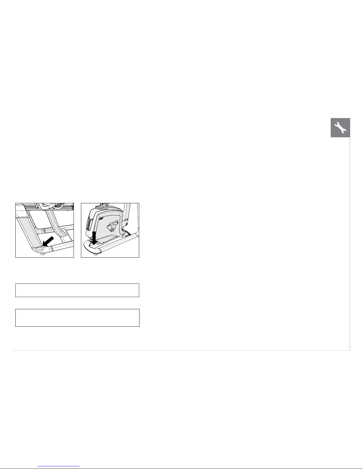
UNPACKING
Unpack the equipment where you will be
using it. Place the carton on a level at
surface. It is recommended that you place
a protective covering on your oor. Never
open box when it is on its side.
IMPORTANT NOTES
During each assembly step, ensure that ALL nuts and bolts
are in place and partially threaded.
Several parts have been pre-lubricated to aid in assembly
and usage. Please do not wipe this off. If you have diculty,
a light application of lithium grease is recommended.
ENGLISH
Page 4
4
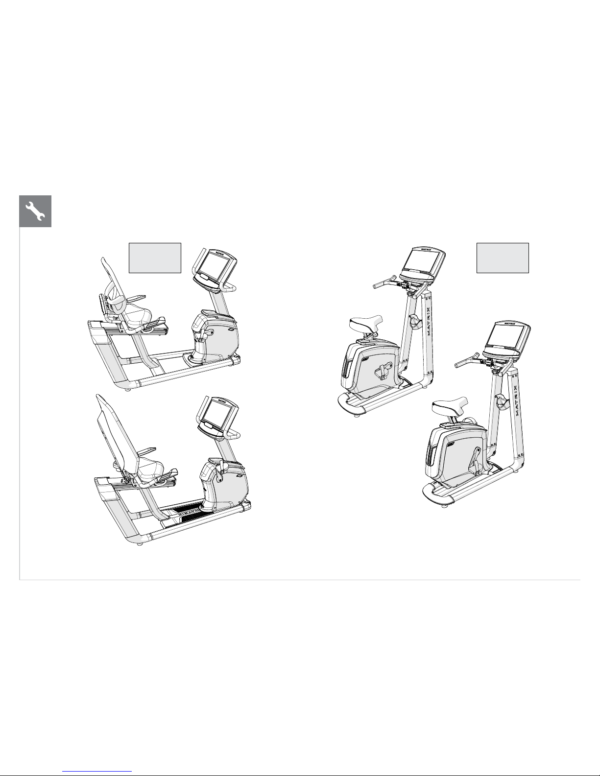
R30 /R50
PAGE 5
U30 / U50
PAGE 10
ENGLISH
Page 5
5
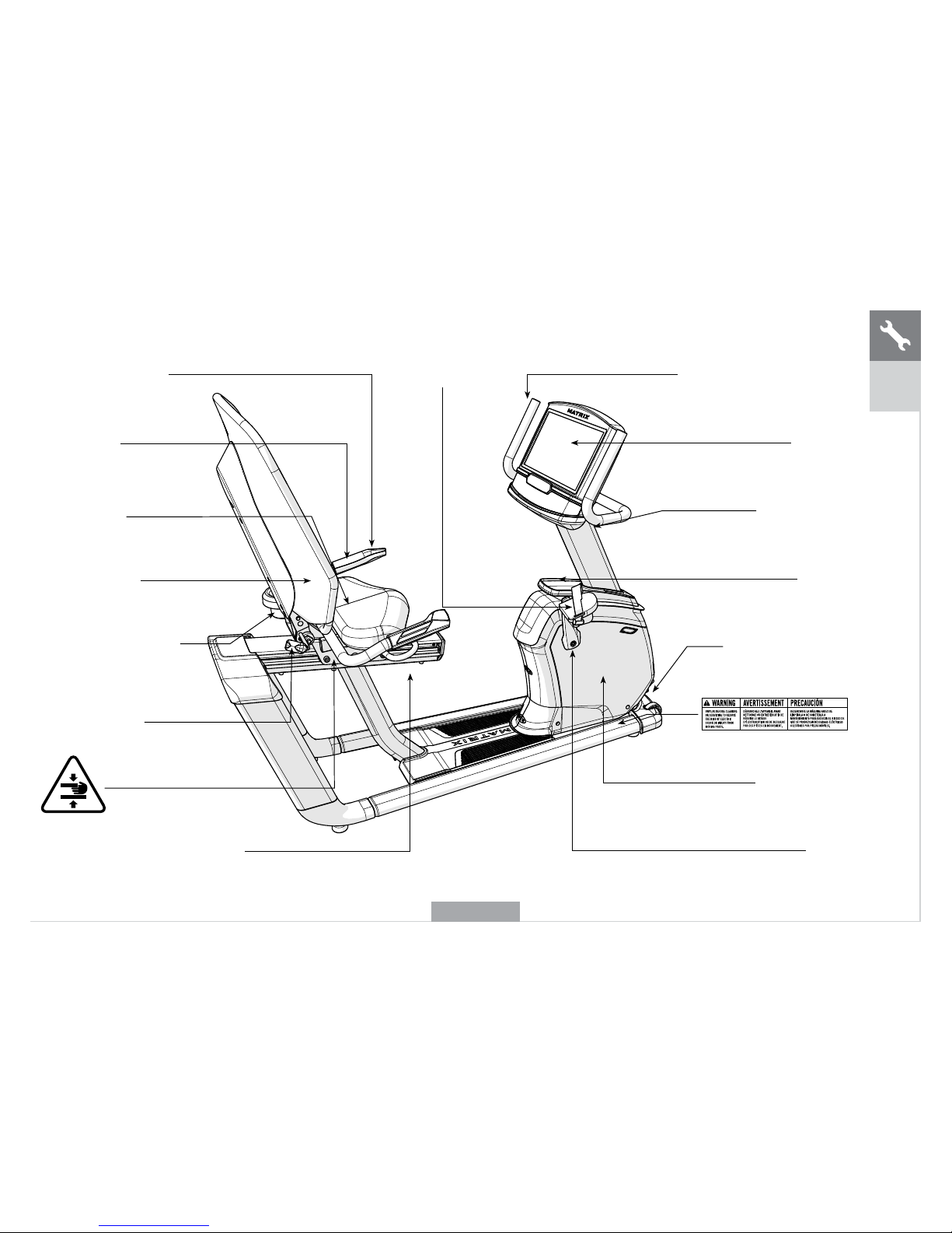
CONSOLE MAST HANDLEBARS
CONSOLE
CONSOLE MAST
TOP CAP
POWER CORD SOCKET
FRONT SHROUD
CRANK
RESISTANCE TOGGLES
PULSE GRIP
HANDLEBARS
SEAT BOTTOM
MESH SEAT BACK
WATER BOTTLE HOLDER
SEAT BACK ADJUSTMENT
LEVER (R50 ONLY)
SEAT POSITION ADJUSTMENT LEVER
R50 SHOWN
R30
R50
PEDALS
ENGLISH
Page 6
6
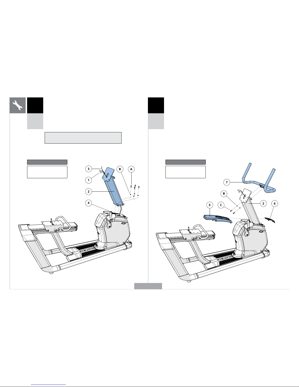
A Open HARDWARE FOR STEP 1.
B Carefully pull the CABLES (1) through the CONSOLE
MAST (2) using the LEAD WIRE (3) located inside
the CONSOLE MAST (2). Discard the lead wire.
C Attach the CONSOLE MAST (2) to MAIN FRAME
(4) using 4 BOLTS (A) and 4 SPRING WASHERS (B).
Torque settings: 23.1 Nm / 17 lb-ft.
Note: Be careful not to pinch any wires while attaching
the console mast.
213
4
A
B
1 2
Hardware For Step 1
Description Qty
A Bolt 4
B Spring Washer 4
7BC
5
6
2
Hardware For Step 2
Description Qty
C Bolt 2
B Spring Washer 2
R30
R50
R30
R50
A Open HARDWARE FOR STEP 2.
B Slide TOP CAP REAR COVER (5) over
CONSOLE MAST (2) and snap into place.
C Slide TOP CAP FRONT COVER (6) over
CONSOLE MAST (2) and snap into place
D Attach HANDLEBARS (7) to CONSOLE MAST (2)
using 2 BOLTS (C) and 2 SPRING WASHERS (B).
Torque settings: 23.1 Nm / 17 lb-ft.
R50 SHOWN
ENGLISH
Page 7
7
D
E
8
9
10
3 4
R30
R50
R30
R50
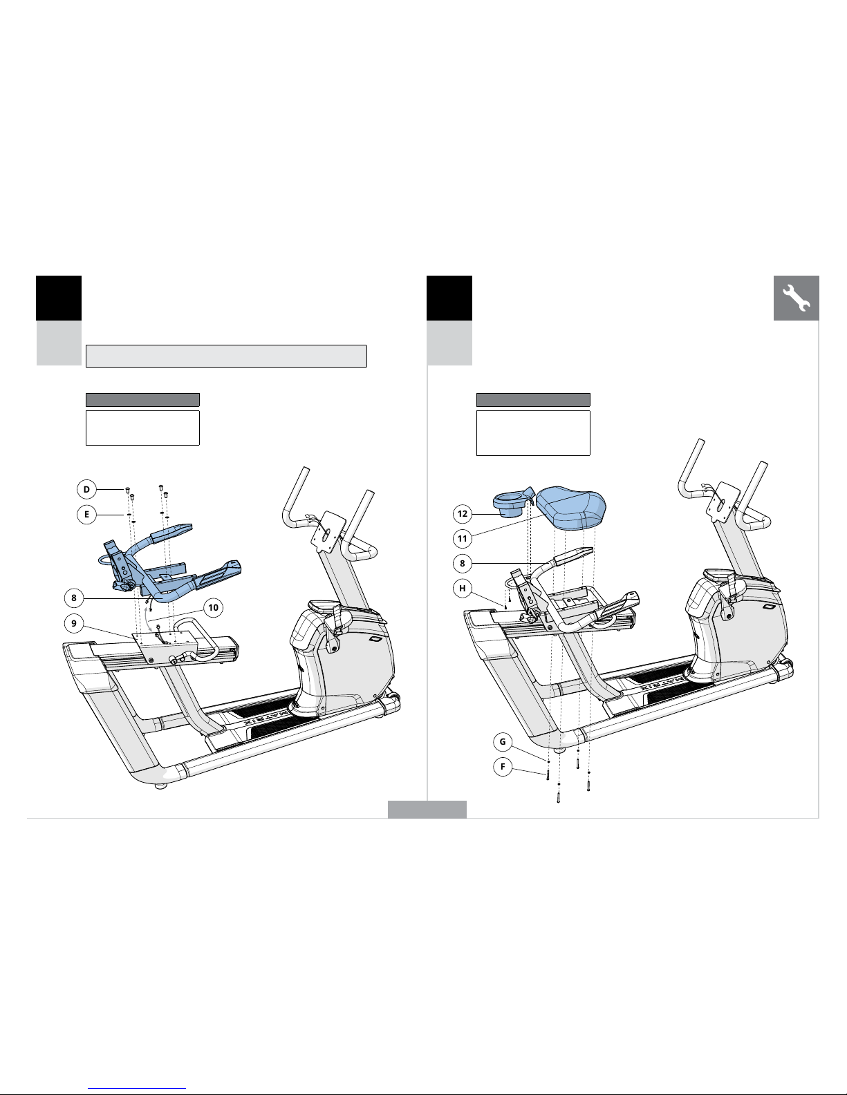
A Open HARDWARE FOR STEP 3
B Attach the SEAT FRAME ASSEMBLY (8) to the SEAT
SLIDE (9) using 4 BOLTS (D) and 4 SPRING WASHERS
(E). Torque settings: 23.1 Nm / 17 lb-ft.
C Connect the CABLES (10).
Note: Be careful not to pinch any wires while attaching the seat frame.
Hardware For Step 3
Description Qty
D Bolt 4
E Spring Washer 4
12
11
8
H
G
F
A Open HARDWARE FOR STEP 4
B Attach the SEAT BOTTOM (11) to the SEAT FRAME
ASSEMBLY (8) using 4 BOLTS (F) and 4 SPRING
WASHERS (G).
C Attach the WATER BOTTLE HOLDER (12) to the
SEAT FRAME ASSEMBLY (8) using 2 SCREWS (H).
Hardware For Step 4
Description Qty
F Bolt 4
G Spring Washer 4
H Screw 2
R50 SHOWN
ENGLISH
Page 8
8
I
8
14
14
13
8
IC15
J
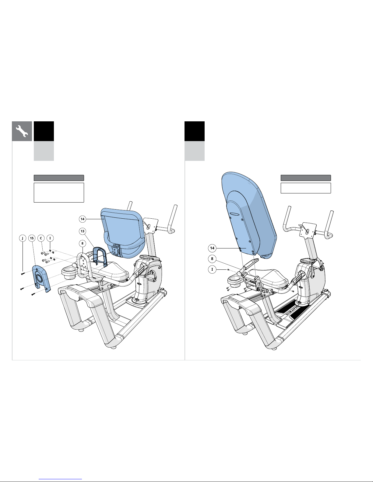
NOTE: This step is for R30 models only.
A Open HARDWARE FOR STEP 5.
B Place the INSIDE COVER (13) over the MESH SEAT BACK
(14) and mount the MESH SEAT BACK (14) to the SEAT
FRAME ASSEMBLY (8) with 4 BOLTS (C) and 4 SPRING
WASHERS (I). Torque settings: 23.1 Nm / 17 lb-ft.
C Attach the OUTSIDE COVER (15) to the SEAT FRAME (8) and
INSIDE COVER (13) with 3 SCREWS (J).
5 5
Hardware For Step 5
Description Qty
C Bolt 4
I Spring Washer 4
J Screw 3
Hardware For Step 5
Description Qty
I Bolt 6
R30 R50
NOTE: This step is for R50 models only.
A Open HARDWARE FOR STEP 5.
B Attach the MESH SEAT BACK (14) to the SEAT
FRAME ASSEMBLY (8) using 6 BOLTS (I). Torque
settings: 9.5 Nm / 7 lb-ft.
ENGLISH
Page 9
9
6 7
R30
R50
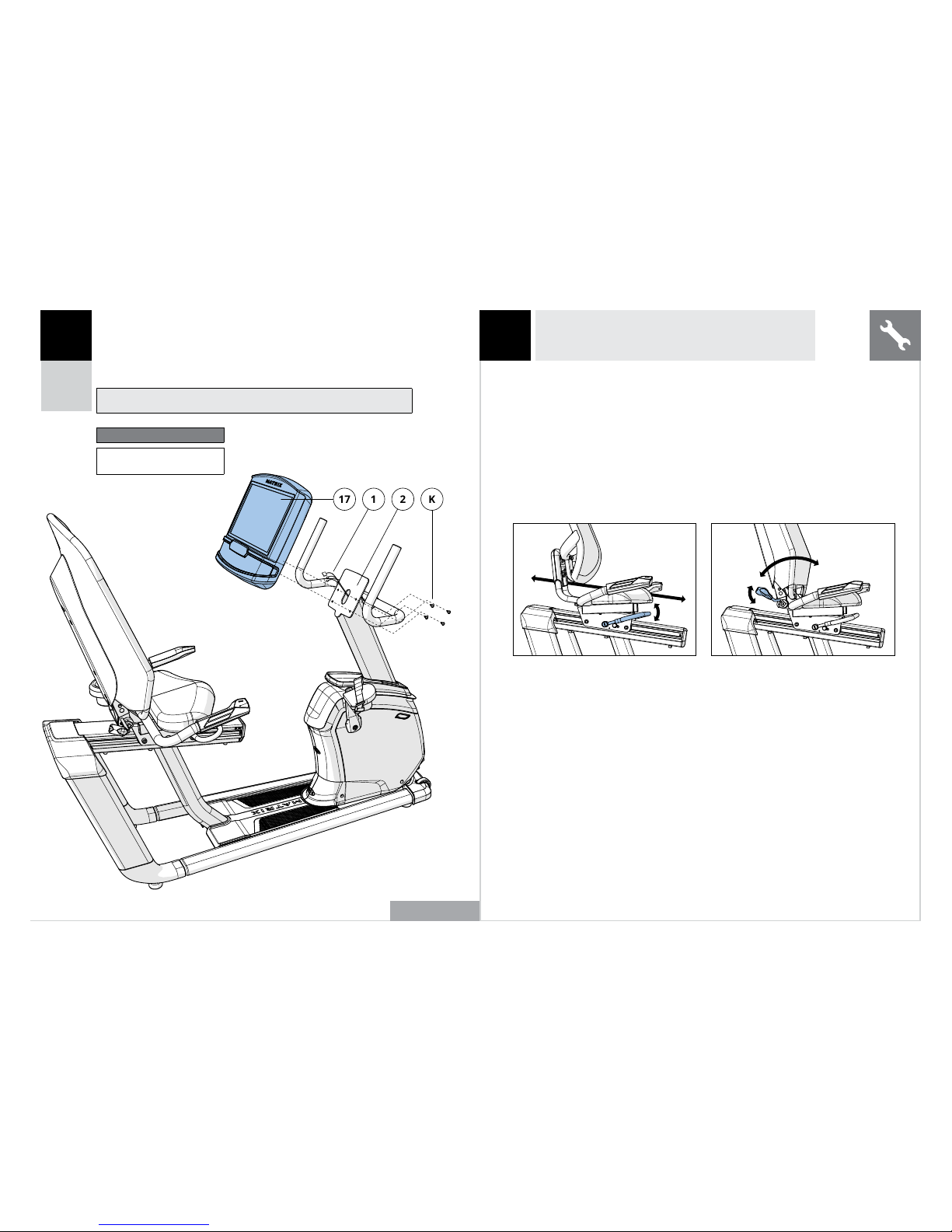
A Open HARDWARE FOR STEP 6.
B Connect the CABLES (1) to the CONSOLE (17) and carefully
tuck the excess cable into the CONSOLE MAST (2).
C Attach the CONSOLE (17) to the CONSOLE
MAST (2) using 4 BOLTS (K).
Note: Be careful not to pinch any wires while attaching the console.
R50 SHOWN
1712
K
R30 / R50 ASSEMBLY COMPLETE!
R30 R50
SEAT ADJUSTMENT
To determine proper seat position, sit on the seat and position the ball
of your foot on the center of the pedal. Your knee should bend slightly
at the furthest pedal position. You should be able to pedal without
locking your knees or shifting your weight from side to side.
NOTE: It is recommended that you do not sit on the seat while adjusting its position.
SEAT POSITION
To adjust, lift up on the adjustment
lever and hold. Then, slide the
seat to a position that puts you
in a comfortable pedaling range
(one that keeps a slight bend in
your knee while your legs are in
the extended position). Release
lever to lock the mechanism.
SEAT BACK ADJUSTMENT (R50)
To adjust the tilt angle of the
seat back, rotate the lever down
(counterclockwise) and lean back
on the mesh seat back until the
desired position is achieved. When
the position is set, rotate the lever
upward (clockwise) until it is snug.
The seat back comes equipped
with a spring return system to
return the seat back to its original
position when the adjustment
lever is released and the user is
not leaning against the seat back.
ENGLISH
Hardware For Step 6
Description Qty
K Bolt 4
Page 10

10
CONSOLE
PULSE GRIP HANDLEBARS
RESISTANCE TOGGLES
SEAT
SEAT ADJUSTMENT LEVER/KNOB
SHROUD
POWER CORD SOCKET
CONSOLE MASTS
WATER BOTTLE HOLDER
TOP CAP
CRANK
PEDALS
U50 SHOWN
U30
U50
ENGLISH
Page 11

11
7
8
4
4
5
6
B
1
2
A
3
A Open HARDWARE FOR STEP 1.
B Attach the SEAT (1) to the SEAT POST (2)
using SEAT BRACKET (3) and 2 BOLTS
(A). Torque settings: 9.5 Nm / 7 lb-ft.
Note: Tighten the bolts evenly by alternating between
front and back until completely tightened.
1 2
Hardware For Step 1
Description Qty
A Bolt 2
U30
U50
U30
U50
U50 SHOWN
A Open HARDWARE FOR STEP 2.
B Carefully pull the CABLE (4) through the RIGHT CONSOLE
MAST (6) using the LEAD WIRE (5) located inside the
CONSOLE MAST (6). Discard the lead wire.
C Attach the RIGHT CONSOLE MAST (6) to
BIKE FRAME (8) using 5 BOLTS (B).
D Attach the LEFT CONSOLE MAST (7) to BIKE FRAME (8)
using 5 BOLTS (B). Leave bolts loose until after step 3.
Note: Be careful not to pinch any wires while attaching the console mast.
Hardware For Step 2
Description Qty
B Bolt 10
ENGLISH
Page 12
12
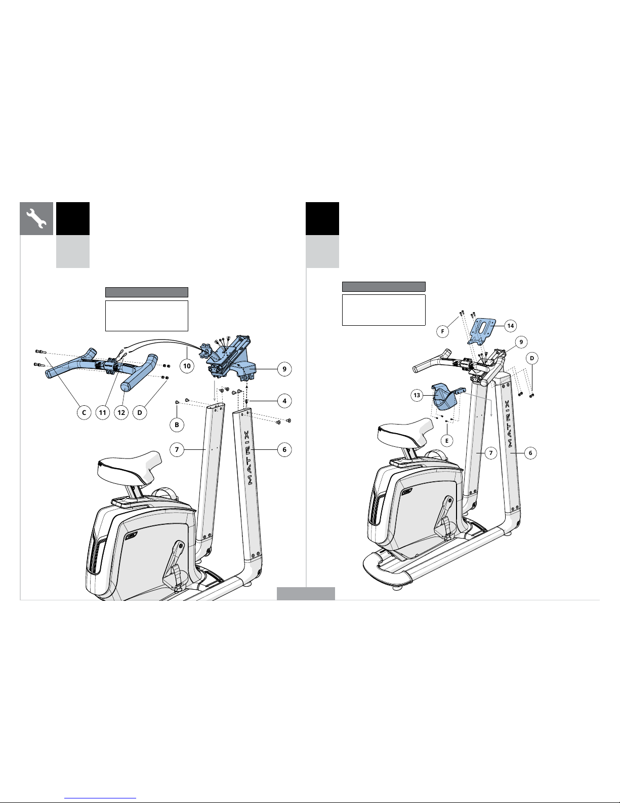
A Open HARDWARE FOR STEP 3.
B Carefully feed the CABLE (4) through the HANDLEBAR
ASSEMBLY (9) and tuck excess wire inside the console masts.
C Attach HANDLEBAR SET (9) to the CONSOLE MASTS (6 & 7)
using 8 BOLTS (B). Torque settings: 23.1 Nm / 17 lb-ft.
D Using the LEAD WIRES (10), carefully feed the WIRES (11) through
the handlebar assembly one set at a time. Discard the lead wires
and wire ties. Attach HANDLEBAR (12) to the HANDLEBAR SET (9)
using 4 BOLTS (C) and 4 NUTS (D). Torque settings: 9.5 Nm / 7 lb-ft.
7
BD1112C
4
9
6
10
3
U30
U50
Hardware For Step 3
Description Qty
B
C
D
Bolt
Bolt (pre-installed)
Nut (pre-installed)
8
4
4
13
7
E
F
6
14
9
D
4
U30
U50
A Open HARDWARE FOR STEP 4.
B Attach the WATER BOTTLE HOLDER (13) to the
CONSOLE MASTS (6 & 7) using 4 SCREWS (E).
C Attach the CONSOLE BRACKET (14)
to the HANDLEBAR SET (9) using 4
BOLTS (F) and 4 NUTS (D).
Hardware For Step 4
Description Qty
E
F
D
Screw
Bolt
Nut
4
4
4
U50 SHOWN
ENGLISH
Page 13

13
14415
G
5 6
U30
U50
A Open HARDWARE FOR STEP 5.
B Connect the CABLES (4) to the CONSOLE (15) and
carefully tuck them into the CONSOLE BRACKET (14).
C Attach the CONSOLE (15) to the CONSOLE
BRACKET (14) using 4 BOLTS (G).
15
17
F
U30
U50
A Open HARDWARE FOR STEP 6.
B Attach the CONSOLE BACK COVER (17) to
the CONSOLE (15) using 4 SCREWS (F).
Hardware For Step 6
Description Qty
F Screw 4
U50 SHOWN
ENGLISH
Hardware For Step 5
Description Qty
G Bolt 4
Page 14

14
7
U30 / U50 ASSEMBLY COMPLETE!
U30 U50
SEAT ADJUSTMENT
To determine proper seat position, sit on the seat and position the ball
of your foot on the center of the pedal. Your knee should bend slightly
at the furthest pedal position. You should be able to pedal without
locking your knees or shifting your weight from side to side.
NOTE: It is recommended that you do not sit on the seat while adjusting its position.
To adjust, loosen the adjustment
knob by turning it two half turns
counterclockwise. Pull out the
knob to unlock the post, and
adjust the post up or down to
the desired setting. Release the
knob to lock in place. Turn the
knob clockwise until tightened.
Please check to be sure seat post is
locked in place before each use.
To adjust, lift up on the adjustment
lever and hold while sliding the post
up or down to the desired setting.
Release the lever to lock in place.
Please check to be sure seat post is
locked in place before each use.
HANDLEBAR POSITION
To adjust, rotate the adjustment
lever down and slide the console
set to a position that puts the
handlebars within comfortable reach.
Lock the mechanism by lifting up
on the adjustment lever until tight.
ENGLISH
Page 15

15
AVERTISSEMENT !
Le processus de montage comporte certaines étapes au cours desquelles
il faut faire particulièrement attention. Il est indispensable de respecter
scrupuleusement les instructions de montage et de s’assurer que toutes les
pièces sont bien serrées. En cas de non-respect des instructions, certaines
parties de l’équipement pourraient être mal serrées, bouger et causer des bruits
gênants. Pour éviter d’endommager l’équipement, relisez les instructions de
montage et prenez les mesures correctives qui s’imposent.
OUTILS INCLUS :
F Tournevis cruciforme
F R30/R50 : clés Allen de 4, de 5 et de 6 mm
F U30/U50 : clés Allen de 2,5, de 4, de 5 et de 8 mm
R30/R50 – PIÈCES INCLUSES :
F 1 cadre de vélo
F 1 support de la console
F 1 poignée
F 1 embout de protection avant
F 1 embout de protection arrière
F 1 châssis de siège
F 1 assise de siège
F 1 porte-bouteille
F 1 dossier de siège en tissu
F 1 protection extérieure
(modèle R30 uniquement)
F 1 protection intérieure
(modèle R30 uniquement)
F 1 câble d’alimentation
F 1 kit de pièces de fixation
La console est vendue séparément
MONTAGE
Avant de commencer, cherchez le numéro de série qui se trouve sur une
étiquette où gure un code à barres et apposée sur votre équipement, puis
notez-le dans les cases ci-dessous.
NUMÉRO DE SÉRIE
NOM DU MODÈLE
F R30
F R50
F U30
F U50
VÉLO D’ENTRAÎNEMENT MATRIX
* Utilisez les informations ci-dessus lorsque vous appelez l’assistance.
EMPLACEMENT DU NUMÉRO DE SÉRIE
BESOIN D’AIDE ?
Pour toute question ou si une pièce est manquante, contactez l’assistance technique. Les coordonnées de
l’assistance sont situées sur la carte d’information.
U30/U50 – PIÈCES INCLUSES :
F 1 cadre de vélo
F 1 selle
F 2 supports de la console
F 1 poignée
F 1 guidon
F 1 support de selle
F 1 porte-bouteille
F 1 protection arrière pour
la console
F 1 câble d’alimentation
F 1 kit de pièces de fixation
La console est vendue séparément
DÉBALLAGE
Déballez l’équipement à l’endroit où
vous allez l’installer. Installez le carton
d’emballage sur une surface plane. Il est
conseillé de placer une toile de protection
sur le sol. N’ouvrez jamais le carton
d’emballage lorsqu’il est couché sur le côté.
REMARQUES IMPORTANTES
À chaque étape du montage, assurez-vous que TOUS les
écrous et boulons sont bien mis en place et partiellement
serrés.
Certaines pièces ont été prélubriées an de faciliter leur
montage et fonctionnement. N’essuyez pas ces pièces pour
essayer d’ôter le lubriant. En cas de diculté, appliquez
une ne couche de graisse au lithium.
FRANÇAIS
Page 16

16
R30/R50
PAGE 17
U30/U50
PAGE 22
FRANÇAIS
Page 17

17
POIGNÉES DU SUPPORT DE LA CONSOLE
CONSOLE
SUPPORT DE LA CONSOLE
EMBOUT
PRISE DE COURANT
CARÉNAGE AVANT
PÉDALIER
COMMUTATEURS DE RÉSISTANCE
POIGNÉES DU CARDIOFRÉQUENCEMÈTRE
ASSISE DE SIÈGE
DOSSIER DE SIÈGE EN TISSU
PORTE-BOUTEILLE
LEVIER DE RÉGLAGE
DU DOSSIER DE SIÈGE
(MODÈLE R50 UNIQUEMENT)
LEVIER DE RÉGLAGE DE
LA POSITION DU SIÈGE
REPRÉSENTATION D’UN MODÈLE R50
R30
R50
PÉDALES
FRANÇAIS
Page 18

18
A Ouvrez le KIT COMPRENANT LES PIÈCES DE
FIXATION POUR LA PREMIÈRE ÉTAPE.
B Sortez délicatement les CÂBLES (1) à travers le
SUPPORT DE LA CONSOLE (2) à l’aide du CÂBLE
CONDUCTEUR (3) situé à l’intérieur du SUPPORT
DE LA CONSOLE (2). Retirez le câble conducteur.
C Fixez le SUPPORT DE LA CONSOLE (2) au CADRE
PRINCIPAL (4) en utilisant 4 BOULONS (A) et
4 RONDELLES ÉLASTIQUES (B). Réglage de couple :
23,1 Nm/17 lb-ft.
Remarque : prenez garde de ne pincer aucun câble
lors de l’installation du support de la console.
213
4
A
B
1 2
Kit de pièces de xation pour l’étape 1
Description Qté
A Boulon 4
B Rondelle élastique 4
7BC
5
6
2
Kit de pièces de xation pour l’étape 2
Description Qté
C Boulon 2
B Rondelle élastique 2
R30
R50
R30
R50
A Ouvrez le KIT COMPRENANT LES PIÈCES DE
FIXATION POUR LA DEUXIÈME ÉTAPE.
B Faites glisser l’EMBOUT DE PROTECTION
ARRIÈRE (5) sur le SUPPORT DE LA
CONSOLE (2) et positionnez-le correctement.
C Faites glisser l’EMBOUT DE PROTECTION
AVANT (6) sur le SUPPORT DE LA CONSOLE (2)
et positionnez-le correctement.
D Fixez les POIGNÉES (7) sur le SUPPORT DE LA
CONSOLE (2) en utilisant 2 BOULONS (C) et
2 RONDELLES ÉLASTIQUES (B). Réglage de couple :
23,1 Nm/17 lb-ft.
REPRÉSENTATION D’UN MODÈLE R50
FRANÇAIS
Page 19

19
D
E
8
9
10
3 4
R30
R50
R30
R50
A Ouvrez le KIT COMPRENANT LES PIÈCES DE
FIXATION POUR LA TROISIÈME ÉTAPE.
B Fixez le CHÂSSIS DE SIÈGE (8) au SYSTÈME DE COULISSEMENT
DU SIÈGE (9) en utilisant 4 BOULONS (D) et 4 RONDELLES
ÉLASTIQUES (E). Réglage de couple : 23,1 Nm/17 lb-ft.
C Branchez les CÂBLES (10).
Remarque : prenez garde de ne pincer aucun câble lors de la fixation du
châssis de siège.
Kit de pièces de xation pour l’étape 3
Description Qté
D Boulon 4
E Rondelle élastique 4
12
11
8
H
G
F
A Ouvrez le KIT COMPRENANT LES PIÈCES DE
FIXATION POUR LA QUATRIÈME ÉTAPE.
B Fixez l’ASSISE DE SIÈGE (11) au CHÂSSIS
DE SIÈGE (8) en utilisant 4 BOULONS (F)
et 4 RONDELLES ÉLASTIQUES (G).
C Attachez le PORTE-BOUTEILLE (12) au CHÂSSIS DE
SIÈGE (8) en utilisant 2 VIS (H).
Kit de pièces de xation pour l’étape 4
Description Qté
F Boulon 4
G Rondelle élastique 4
H Vis 2
REPRÉSENTATION D’UN MODÈLE R50
FRANÇAIS
Page 20

20
I
8
14
14
13
8
IC15
J
REMARQUE : cette étape concerne les modèles R30 uniquement.
A Ouvrez le KIT COMPRENANT LES PIÈCES DE
FIXATION POUR LA CINQUIÈME ÉTAPE.
B Placez la PROTECTION INTÉRIEURE (13) sur le DOSSIER DE SIÈGE
EN TISSU (14) et montez le DOSSIER DE SIÈGE EN TISSU (14)
sur le CHÂSSIS DE SIÈGE (8) en utilisant 4 BOULONS (C) et
4 RONDELLES ÉLASTIQUES (I). Réglage de couple : 23,1 Nm/17 lb-ft.
C Fixez la PROTECTION EXTÉRIEURE (15) sur le CHÂSSIS DE SIÈGE (8)
et la PROTECTION INTÉRIEURE (13) en utilisant 3 VIS (J).
5 5
Kit de pièces de xation pour l’étape 5
Description Qté
C Boulon 4
I Rondelle élastique 4
J Vis 3
Kit de pièces de xation pour l’étape 5
Description Qté
I Boulon 6
R30 R50
REMARQUE : cette étape concerne
les modèles R50 uniquement.
A Ouvrez le KIT COMPRENANT LES PIÈCES DE
FIXATION POUR LA CINQUIÈME ÉTAPE.
B Attachez le DOSSIER DE SIÈGE EN TISSU (14) au
CHÂSSIS DE SIÈGE (8) en utilisant 6 BOULONS (I).
Réglage de couple : 9,5 Nm/7 lb-ft.
FRANÇAIS
Page 21

21
6 7
R30
R50
A Ouvrez le KIT COMPRENANT LES PIÈCES DE
FIXATION POUR LA SIXIÈME ÉTAGE.
B Branchez les CÂBLES (1) sur la CONSOLE (17) et rentrez avec
précaution l’excès de câble dans le SUPPORT DE LA CONSOLE (2).
C Fixez la CONSOLE (17) au SUPPORT DE LA
CONSOLE (2) en utilisant 4 BOULONS (K).
Remarque : prenez garde de ne pincer aucun câble lors de l’installation
de la console.
REPRÉSENTATION D’UN MODÈLE R50
1712
K
R30/R50 – MONTAGE TERMINÉ !
R30 R50
RÉGLAGE DU SIÈGE
Afin de déterminer la position adéquate du siège, installez-vous dessus et placez
la plante de votre pied au centre de la pédale. Votre genou doit être légèrement
plié lorsque la pédale est dans la position la plus éloignée. Vous devriez pouvoir
pédaler sans bloquer les genoux ni balancer votre corps d’un côté à l’autre.
REMARQUE : il est conseillé de ne pas s’asseoir sur le
siège pendant le réglage de sa position.
POSITION DU SIÈGE
Pour ajuster le siège, soulevez le
levier de réglage et maintenez-le
dans cette position. Faites ensuite
glisser le siège dans la position qui
vous semble la plus confortable (qui
vous permet de plier légèrement
les genoux alors que vos jambes
sont étendues). Relâchez le levier
pour verrouiller cette position.
RÉGLAGE DU DOSSIER DU
SIÈGE (MODÈLE R50)
Pour régler l’inclinaison du dossier
du siège, tournez le levier vers le
bas (dans le sens antihoraire) et
allongez-vous sur le dossier de siège
en tissu jusqu’à atteindre la position
souhaitée. Une fois la position
trouvée, tournez le levier vers le
haut (dans le sens horaire) jusqu’à
ce qu’il soit bien serré. Le dossier du
siège est équipé d’un système de
retour par ressorts lui permettant
de revenir dans sa position initiale
lorsque le levier de réglage est
relâché et que l’utilisateur n’est pas
assis contre le dossier du siège.
FRANÇAIS
Kit de pièces de xation pour l’étape 6
Description Qté
K Boulon 4
Page 22

22
CONSOLE
POIGNÉES DU CARDIO-FRÉQUENCEMÈTRE
COMMUTATEURS DE RÉSISTANCE
SELLE
LEVIER/MOLETTE DE
RÉGLAGE DE LA SELLE
CARÉNAGE
PRISE DE COURANT
SUPPORTS DE LA CONSOLE
PORTE-BOUTEILLE
EMBOUT
PÉDALIER
PÉDALES
REPRÉSENTATION D’UN MODÈLE U50
U30
U50
FRANÇAIS
Page 23

23
7
8
4
4
5
6
B
1
2
A
3
A Ouvrez le KIT COMPRENANT LES PIÈCES DE
FIXATION POUR LA PREMIÈRE ÉTAPE.
B Fixez la SELLE (1) à la TIGE DE LA SELLE (2) en utilisant le SUPPORT
DE SELLE (3) et 2 BOULONS (A). Réglage de couple : 9,5 Nm/7 lb-ft.
Remarque : serrez fermement les boulons, en alternant, jusqu’à ce
qu’ils soient bien fixés.
1 2
Kit de pièces de xation pour l’étape 1
Description Qté
A Boulon 2
U30
U50
U30
U50
REPRÉSENTATION D’UN MODÈLE U50
A Ouvrez le KIT COMPRENANT LES PIÈCES DE
FIXATION POUR LA DEUXIÈME ÉTAPE.
B Sortez délicatement le CÂBLE (4) à travers le SUPPORT DROIT DE LA
CONSOLE (6) à l’aide du CÂBLE CONDUCTEUR (5) situé à l’intérieur
du SUPPORT DE LA CONSOLE (6). Retirez le câble conducteur.
C Fixez le SUPPORT DROIT DE LA CONSOLE (6) au CADRE
DE VÉLO (8) en utilisant 5 BOULONS (B).
D Fixez le SUPPORT GAUCHE DE LA CONSOLE (7) au CADRE DE VÉLO (8) en
utilisant 5 BOULONS (B). Ne serrez pas les boulons avant la fin de l’étape 3.
Remarque : prenez garde de ne pincer aucun câble lors de l’installation du
support de la console.
Kit de pièces de xation pour l’étape 2
Description Qté
B Boulon 10
FRANÇAIS
Page 24

24
7
BD1112C
4
9
6
10
13
7
E
F
6
14
9
D
A Ouvrez le KIT COMPRENANT LES PIÈCES DE
FIXATION POUR LA TROISIÈME ÉTAPE.
B Faites passer délicatement le CÂBLE (4) par le SUPPORT DU GUIDON (9)
et rentrez l’excès de câble dans les supports de la console.
C Fixez le GUIDON (9) aux SUPPORTS DE LA CONSOLE (6 ET 7) en
utilisant 8 BOULONS (B). Réglage de couple : 23,1 Nm/17 lb-ft.
D À l’aide du CÂBLES CONDUCTEUR (10), faites délicatement passer les CÂBLES
(11) dans le support du guidon un jeu à la fois. Retirez le câble conducteur et
les liens des cables. Fixez le GUIDON (12) sur son SUPPORT (9) en utilisant
4 BOULONS (C) et 4 ÉCROUS (D). Réglage de couple : 9,5 Nm/7 lb-ft.
3 4
U30
U50
U30
U50
Kit de pièces de xation pour l’étape 3
Description Qté
B
C
D
Boulon
Boulon
Écrou
8
4
4
A Ouvrez le KIT COMPRENANT LES PIÈCES DE
FIXATION POUR LA QUATRIÈME ÉTAPE.
B Attachez le PORTE-BOUTEILLE (13) aux SUPPORTS
DE LA CONSOLE (6 ET 7) en utilisant 4 VIS (E).
C Fixez le MONTANT DE LA CONSOLE (14) au GUIDON (9)
en utilisant 4 BOULONS (F) et 4 ÉCROUS (D).
Kit de pièces de xation pour l’étape 4
Description Qté
E
F
D
Vis
Boulon
Écrou
4
4
4
REPRÉSENTATION D’UN MODÈLE U50
FRANÇAIS
Page 25

25
14415
G
15
17
F
5 6
U30
U50
A Ouvrez le KIT COMPRENANT LES PIÈCES DE
FIXATION POUR LA CINQUIÈME ÉTAPE.
B Branchez les CÂBLES (4) sur la CONSOLE (15) et rentrez-les
avec précaution dans le MONTANT DE LA CONSOLE (14).
C Fixez la CONSOLE (15) à son MONTANT (14) en utilisant 4 VIS (G).
U30
U50
A Ouvrez le KIT COMPRENANT LES PIÈCES
DE FIXATION POUR LA SIXIÈME ÉTAPE.
B Attachez la PROTECTION ARRIÈRE
POUR LA CONSOLE (17) à la
CONSOLE (15) en utilisant 4 VIS (F).
Kit de pièces de xation pour l’étape 6
Description Qté
F Vis 4
REPRÉSENTATION D’UN MODÈLE U50
FRANÇAIS
Kit de pièces de xation pour l’étape 5
Description Qté
G Vis 4
Page 26

26
7
U30/U50 – MONTAGE TERMINÉ !
U30 U50
RÉGLAGE DU SIÈGE
Afin de déterminer la position adéquate du siège, installez-vous dessus et placez
la plante de votre pied au centre de la pédale. Votre genou doit être légèrement
plié lorsque la pédale est dans la position la plus éloignée. Vous devriez pouvoir
pédaler sans bloquer les genoux ni balancer votre corps d’un côté à l’autre.
REMARQUE : il est conseillé de ne pas s’asseoir sur le
siège pendant le réglage de sa position.
Pour ajuster la position de la selle,
desserrez la molette de réglage en la
tournant de deux demi-tours dans le
sens antihoraire. Tirez sur la molette
pour déverrouiller la tige et ajustez-la
ensuite, vers le haut ou vers le bas, pour
obtenir la position souhaitée. Relâchez
la molette pour verrouiller la tige dans
cette position. Tournez la molette dans
le sens horaire jusqu’à ce qu’elle soit
bien serrée. Avant chaque utilisation,
veillez à ce que la tige de la selle soit
bien verrouillée dans sa position.
Pour ajuster la position de la selle,
soulevez le levier de réglage et
maintenez-le tout en faisant glisser la
tige vers le haut ou vers le bas, pour
obtenir la position souhaitée. Relâchez
le levier pour verrouiller la tige dans
cette position. Avant chaque utilisation,
veillez à ce que la tige de la selle soit
bien verrouillée dans sa position.
POSITION DU GUIDON
Pour ajuster la position du guidon,
faites tourner le levier de réglage
vers le bas tout en faisant glisser
la console dans une position vous
permettant d’atteindre facilement
les poignées. Pour verrouiller cette
position, soulevez le levier de réglage
jusqu’à ce qu’il soit bien serré.
FRANÇAIS
Page 27

27
ADVERTENCIA
El proceso de montaje tiene varios pasos que requieren una atención especial. Es
muy importante seguir correctamente las instrucciones de montaje y asegurarse
de que todas las partes están rmemente ajustadas. Si no se siguen correctamente
las instrucciones de montaje, es posible que haya piezas del equipo que no estén
apretadas y provoquen ruidos molestos. Para evitar daños en el equipo, debe consultar
las instrucciones de montaje y llevar a cabo las medidas correctivas que se precisen.
HERRAMIENTAS INCLUIDAS:
F Destornillador de estrella
F R30/R50: Llave hexagonal de 6 mm, llave hexagonal de 5 mm, llave hexagonal de 4 mm
F U30/U50: Llave hexagonal de 5 mm, llave hexagonal de 4 mm, llave hexagonal de 2,5 mm,
llave de 8 mm
PIEZAS INCLUÍDAS EN
LOS MODELOS R30 / R50:
F
1 bastidor de bicicleta
F
1 mástil de consola
F
1 manillar
F
1 cubierta delantera de la tapa superior
F
1 cubierta trasera de la tapa superior
F
1 conjunto de la estructura del asiento
F
1 pieza inferior del asiento
F
1 portabotella
F
1 respaldo de malla
F
1 cubierta exterior (solamente para
el modelo R30)
F
1 cubierta interior (solamente para
el modelo R30)
F
1 cable de alimentación
F
1 bolsa de accesorios
La consola se vende por separado.
MONTAJE
Antes de comenzar, busque el número de serie del equipo, que se halla ubicado
en una etiqueta de código de barras y anótelo en el espacio que se encuentra a
continuación.
NÚMERO DE SERIE
NOMBRE DEL MODELO:
F R30
F R50
F U30
F U50
BICICLETA ESTÁTICA MATRIX
* Indique la información que se menciona arriba cuando llame a la asistencia técnica.
UBICACIÓN DEL NÚMERO DE SERIE
¿NECESITA AYUDA?
Si tiene alguna duda o le falta algún componente, póngase en contacto con el servicio de asistencia técnica
al consumidor. Puede encontrar la información de contacto en la tarjeta de información.
PIEZAS INCLUÍDAS EN
LOS MODELOS U30 / U50:
F
1 bastidor de bicicleta
F
1 asiento
F
2 mástiles de consola
F
1 manillar
F
1 kit de manillar
F
1 soporte de asiento de bicicleta
F
1 portabotella
F
1 cubiertas posterior de la
consola
F
1 cable de alimentación
F
1 bolsa de accesorios
La consola se vende por separado.
DESEMBALAJE
Desembale el equipo donde lo vaya a
emplear. Coloque el paquete sobre una
supercie plana nivelada. Se recomienda
que coloque alguna protección sobre
el suelo. Nunca abra la caja si esta está
sobre un lateral.
NOTAS IMPORTANTES
Asegúrese de que TODOS los pernos y todas las tuercas
están en su sitio y parcialmente apretados en todos los
pasos del montaje.
Varios componentes se han lubricado previamente para
facilitar el montaje y la utilización. Por favor, no limpie el
lubricante. Si tiene dicultades, se recomienda aplicar una
ligera capa de grasa de litio.
ESPAÑOL
Page 28

28
R30 /R50
PÁGINA 29
U30 / U50
PÁGINA 34
ESPAÑOL
Page 29

29
EMPUÑADURAS DEL MÁSTIL
DE LA CONSOLA
CONSOLA
MÁSTIL DE LA CONSOLA
TAPA SUPERIOR
ENCHUFE DEL CABLE
DE ALIMENTACIÓN
CARCASA DELANTERA
BIELAS
CONMUTADORES DE RESISTENCIA
ASIDEROS CON PULSÓMETRO
PIEZA INFERIOR DEL ASIENTO
RESPALDO DE MALLA
PORTABOTELLA
PALANCA DE AJUSTE DEL
RESPALDO (SOLAMENTE
EN EL MODELO R50)
PALANCA DE AJUSTE DE
LA POSICIÓN DEL ASIENTO
FIGURA DEL MODELO R50
R30
R50
PEDALES
ESPAÑOL
Page 30

30
A Abra los COMPONENTES NECESARIOS PARA EL PASO 1.
B Tire con cuidado de los CABLES (1) para pasarlos a través del
MÁSTIL DE LA CONSOLA (2) sirviéndose del CABLE GUÍA (3)
situado en el interior del MÁSTIL DE LA CONSOLA (2).
Deseche el cable guía.
C Acople el MÁSTIL DE LA CONSOLA (2) al BASTIDOR DE
LA ESTRUCTURA PRINCIPAL (4) utilizando 4 PERNOS (A)
y 4 ARANDELAS DE PRESIÓN (B). Ajustes del par de apriete:
23,1 Nm / 17 lb-ft.
Nota: Tenga cuidado de no estrangular ningún cable al instalar
el mástil de la consola.
213
4
A
B
1 2
Componentes necesarios para
el paso 1
Descripción Cantidad
A Perno 4
B Arandela de presión 4
7BC
5
6
2
Componentes necesarios para
el paso 2
Descripción Cantidad
C Perno 2
B Arandela de presión 2
R30
R50
R30
R50
A Abra los COMPONENTES NECESARIOS PARA
EL PASO 2.
B Deslice la CUBIERTA TRASERA DE LA TAPA
SUPERIOR (5) encajándola sobre el MÁSTIL DE
LA CONSOLA (2) y haga que encaje en su sitio.
C Deslice la CUBIERTA DELANTERA DE LA TAPA
SUPERIOR (6) encajándola sobre el MÁSTIL DE
LA CONSOLA (2) y haga que encaje en su sitio.
D Acople las EMPUÑADURAS (7) al MÁSTIL DE
LA CONSOLA (2) utilizando 2 PERNOS (C) y
2 ARANDELAS DE PRESIÓN (B). Ajustes del
par de apriete: 23,1 Nm / 17 lb-ft.
FIGURA DEL MODELO R50
ESPAÑOL
Page 31

31
D
E
8
9
10
3 4
R30
R50
R30
R50
A Abra los COMPONENTES NECESARIOS PARA EL PASO 3.
B Acople el CONJUNTO DE LA ESTRUCTURA DEL ASIENTO (8)
al SOPORTE DESLIZANTE DEL ASIENTO (9) utilizando 4 PERNOS (D)
y 4 ARANDELAS DE PRESIÓN (E). Ajustes del par de apriete:
23,1 Nm / 17 lb-ft.
C Conecte los CABLES (10).
Nota: Tenga cuidado de no estrangular ningún cable al instalar la
estructura del asiento.
Componentes necesarios para
el paso 3
Descripción Cantidad
D Perno 4
E Arandela de presión 4
12
11
8
H
G
F
A Abra los COMPONENTES NECESARIOS PARA EL PASO 4.
B Acople la PIEZA INFERIOR DEL ASIENTO (11) al
CONJUNTO DE LA ESTRUCTURA DEL ASIENTO (8)
utilizando 4 PERNOS (F) y 4 ARANDELAS DE PRESIÓN (G).
C Acople el PORTABIDÓN (12) al CONJUNTO DE LA
ESTRUCTURA DEL ASIENTO (8) con 2 TORNILLOS (H).
Componentes necesarios para
el paso 4
Descripción Cantidad
F Perno 4
G Arandela de presión 4
H Tornillo 2
FIGURA DEL MODELO R50
ESPAÑOL
Page 32

32
I
8
14
14
13
8
IC15
J
NOTA: Este paso solamente corresponde al modelo R30.
A Abra los COMPONENTES NECESARIOS PARA EL PASO 5.
B Coloque la CUBIERTA INTERIOR (13) sobre el RESPALDO DE MALLA
(14) y monte el RESPALDO DE MALLA (14) en el CONJUNTO DE LA
ESTRUCTURA DEL ASIENTO (8) con 4 PERNOS (C) y 4 ARANDELAS
DE PRESIÓN (I). Ajustes del par de apriete: 23,1 Nm / 17 lb-ft.
C Instale la CUBIERTA EXTERIOR (15) en la ESTRUCTURA DEL
ASIENTO
(8) y la CUBIERTA INTERIOR (13) con 3 TORNILLOS (J).
5 5
Componentes necesarios para
el paso 5
Descripción Cantidad
C Perno 4
I Arandela de presión 4
J Tornillo 3
Componentes necesarios para
el paso 5
Descripción Cantidad
I Perno 6
R30 R50
NOTA: Este paso solamente corresponde al modelo R50.
A Abra los COMPONENTES NECESARIOS PARA EL PASO 5.
B Acople el RESPALDO DE MALLA (14) al CONJUNTO DE LA
ESTRUCTURA DEL ASIENTO (8) con 6 PERNOS (I). Ajustes
del par de apriete: 9,5 Nm / 7 lb-ft.
ESPAÑOL
Page 33

33
6 7
R30
R50
A Abra los COMPONENTES NECESARIOS PARA EL PASO 6.
B Conecte los CABLES (1) a la CONSOLA (17) e introduzca presionando
suavemente el exceso de cable dentro del MÁSTIL DE LA CONSOLA (2).
C Instale la CONSOLA (17) acoplándola al MÁSTIL DE LA CONSOLA (2) con
4 PERNOS (K).
Nota: Tenga cuidado de no pillar ningún cable al instalar la consola.
FIGURA DEL MODELO R50
1712
K
¡HA COMPLETADO EL MONTAJE DEL R30 / R50!
R30 R50
AJUSTE DEL ASIENTO
Para determinar cuál es la posición correcta del asiento, siéntese encima y coloque la
zona de los metatarsos de los pies (junto a los dedos) sobre el centro de los pedales.
Al llevar el pedal hasta la posición más lejana, las rodillas se deberían flexionar
ligeramente. Debería ser capaz de pedalear sin tener que bloquear las rodillas
(flexionándolas hasta el tope) ni de balancear el peso del cuerpo de un lado al otro.
NOTA: Le recomendamos que no se siente sobre el asiento mientras está ajustando
su posición.
POSICIÓN DEL ASIENTO
Para ajustar la colocación, levante
y sostenga la palanca de ajuste.
A continuación, deslice el asiento
hasta una posición desde la cual
pedalee con comodidad (una postura
donde las rodillas se flexionen
ligeramente cuando las piernas se
estiren al máximo). Suelte la palanca
para bloquear el mecanismo.
AJUSTE DEL RESPALDO
DEL ASIENTO (R50)
Para ajustar el ángulo de reclinación
del respaldo del asiento, gire la
palanca hacia abajo (en sentido
contrario al de las agujas del reloj)
y recuéstese contra el respaldo
forrado de malla hasta que alcance
la posición deseada. Cuando haya
fijado la posición, gire la palanca
hacia arriba (en el sentido de las
agujas del reloj) hasta que llegue
a una posición cómoda. El respaldo
del asiento viene equipado con un
sistema de resortes que lo devuelve a
su posición original cuando se suelta
la palanca de ajuste y el usuario no
está recostado contra el respaldo.
ESPAÑOL
Componentes necesarios para
el paso 6
Descripción Cantidad
K Perno 4
Page 34

34
CONSOLA
ASIDEROS CON PULSÓMETRO
CONMUTADORES DE RESISTENCIA
ASIENTO
PALANCA/CONTROL DE AJUSTE
DEL ASIENTO
CARCASA
ENCHUFE DEL CABLE
DE ALIMENTACIÓN
MÁSTILES DE LA CONSOLA
PORTABOTELLA
TAPA SUPERIOR
BIELAS
PEDALES
FIGURA DEL MODELO U50
U30
U50
ESPAÑOL
Page 35

35
7
8
4
4
5
6
B
1
2
A
3
A Abra los COMPONENTES NECESARIOS PARA EL PASO 1.
B Instale el ASIENTO (1) en el PILAR DEL ASIENTO (2)
utilizando el SOPORTE DEL ASIENTO (3) y 2 PERNOS (A).
Ajustes del par de apriete: 9,5 Nm / 7 lb-ft.
Nota: Apriete los pernos de manera uniforme, alternando de los
delanteros a los traseros hasta que todos estén bien ajustados.
1 2
Componentes necesarios para
el paso 1
Descripción Cantidad
A Perno 2
U30
U50
U30
U50
FIGURA DEL MODELO U50
A Abra los COMPONENTES NECESARIOS PARA EL PASO 2.
B Tire con cuidado del CABLE (4) para pasarlo a través del MÁSTIL
DERECHO DE LA CONSOLA (6) utilizando el CABLE GUÍA (5) situado
dentro del MÁSTIL DE LA CONSOLA (6). Deseche el cable guía.
C Instale el MÁSTIL DERECHO DE LA CONSOLA (6) en el BASTIDOR DE
BICICLETA (8) utilizando 5 PERNOS (B).
D Instale el MÁSTIL IZQUIERDO DE LA CONSOLA (7) en el BASTIDOR
DE BICICLETA (8) utilizando 5 PERNOS (B). Deje los pernos aflojados
hasta superar el paso 3.
Nota: Tenga cuidado de no estrangular ningún cable al instalar el mástil
de la consola.
Componentes necesarios para
el paso 2
Descripción Cantidad
B Perno 10
ESPAÑOL
Page 36

36
7
BD1112C
4
9
6
10
13
7
E
F
6
14
9
D
A Abra los COMPONENTES NECESARIOS PARA EL PASO 3.
B Introduzca con cuidado el CABLE (4) pasándolo por el CONJUNTO
DE LA ESTRUCTURA DEL MANILLAR (9) y guarde el cable sobrante
recogiéndolo dentro de los mástiles de la consola.
C Instale el KIT DE MANILLAR (9) en los MÁSTILES DE LA CONSOLA (6 Y 7)
utilizando 8 PERNOS (B). Ajustes del par de apriete: 23,1 Nm / 17 lb-ft.
D Sirviéndose del CABLES GUÍA (10), introduzca con cuidado los CABLES
(11) pasándolos a través del kit del manillar un juego a la vez. Deseche
el cable guía y las ataduras de cables. Acople el MANILLAR (12) al KIT
DE MANILLAR (9) utilizando 4 PERNOS (C) y 4 TUERCAS (D). Ajustes del
par de apriete: 9,5 Nm / 7 lb-ft.
3 4
U30
U50
U30
U50
Componentes necesarios para el paso 3
Descripción Cantidad
B
C
D
Perno
Perno
Tuerca
8
4
4
A Abra los COMPONENTES NECESARIOS PARA EL PASO 4.
B Acople el PORTABIDÓN (13) a los MÁSTILES DE LA
CONSOLA (6 Y 7) utilizando 4 TORNILLOS (E).
C Instale el SOPORTE DE LA CONSOLA (14) al KIT DE
MANILLAR (9) utilizando 4 PERNOS (F) y 4 TUERCAS (D).
Componentes necesarios para
el paso 4
Descripción Cantidad
E
F
D
Tornillo
Perno
Tuerca
4
4
4
FIGURA DEL MODELO U50
ESPAÑOL
Page 37

37
14415
G
15
17
F
5 6
U30
U50
A Abra los COMPONENTES NECESARIOS PARA EL PASO 5.
B Conecte los CABLES (4) a la CONSOLA (15) e introdúzcalos
con cuidado dentro del SOPORTE DE LA CONSOLA (14).
C Acople la CONSOLA (15) al SOPORTE DE LA
CONSOLA (14) utilizando los 4 PERNOS (G).
U30
U50
A Abra los COMPONENTES NECESARIOS PARA
EL PASO 6.
B Acople la CUBIERTA TRASERA DE LA CONSOLA (16)
a la CONSOLA (15) utilizando 4 TORNILLOS (F).
Componentes necesarios para
el paso 6
Descripción Cantidad
F Tornillo 4
FIGURA DEL MODELO U50
ESPAÑOL
Componentes necesarios para
el paso 5
Descripción Cantidad
G Perno 4
Page 38

38
7
¡HA COMPLETADO EL MONTAJE DEL U30 / U50!
U30
2
1
3
4
A
B
U50
AJUSTE DEL ASIENTO
Para determinar cuál es la posición correcta del asiento, siéntese encima y coloque la
zona de los metatarsos de los pies (junto a los dedos) sobre el centro de los pedales.
Al llevar el pedal hasta la posición más lejana, las rodillas se deberían flexionar
ligeramente. Debería ser capaz de pedalear sin tener que bloquear las rodillas
(flexionándolas hasta el tope) ni de balancear el peso del cuerpo de un lado al otro.
NOTA: Le recomendamos que no se siente sobre el asiento mientras está ajustando
su posición.
Para ajustarlo, afloje el control de
ajuste haciéndolo girar dos medias
vueltas en sentido contrario al de
las agujas del reloj. Tire del control
hacia fuera para desbloquear el pilar
y ajústelo hacia abajo o arriba, hasta
alcanzar la posición deseada. Para
volver a bloquear el control, suéltelo.
Gire el control en el sentido de las
agujas del reloj hasta que quede
apretado. Compruebe que el pilar
del asiento esté bloqueado en su
posición correcta antes de cada uso.
Para ajustarlo, levante y sostenga
elevada la palanca de ajuste mientras
desliza el pilar hacia arriba o abajo
hasta alcanzar la posición deseada.
Para volver a bloquear la palanca,
suéltela. Compruebe que el pilar
del asiento esté bloqueado en su
posición correcta antes de cada uso.
POSICIÓN DEL MANILLAR
Para ajustarlo, gire la palanca de
ajuste hacia abajo y deslice el kit
de la consola hasta una posición
donde los asideros queden a una
distancia cómoda para agarrarlos.
Para bloquear el mecanismo,
levante la palanca de ajuste
hasta que quede apretada.
ESPAÑOL
Page 39

39
Page 40

© 2016 Johnson Health Tech
Rev 1.2 ENG FRE SPE
R30 U30
R50 U50
 Loading...