

Page 1
Cycles_OM_090430.indd 1 4/30/09 10:40 AM
Page 2

Cycles_OM_090430.indd 2 4/30/09 10:40 AM
Page 3

CHAPTER 1: IMPORTANT SAFETY INSTRUCTIONS PAGES
1.1 Read and Save These Instructions .................................................................. 01
1.2 Setting up the Cycle ...................................................................................... 01
1.3 Installation Requirements .............................................................................. 01
1.4 Preventative Maintenance and Cleaning Tips ................................................... 01
CHAPTER 2: ADJUSTING THE SEAT
2.1 Recumbent Seat Height ....................................................................................... 02
2.2 Upright Seat Height ............................................................................................. 02
2.3 Hybrid Seat Height ............................................................................................... 02
CHAPTER 3: PLACEMENT OF SERIAL NUMBER ON CYCLES
3.1 Recumbent Cycle ................................................................................................ 02
3.2 Upright Cycle ...................................................................................................... 02
3.3 Hybrid Cycle .......................................................................................................... 02
CHAPTER 4: USING THE UPRIGHT, RECUMBENT OR HYBRID CYCLE™
4.1 Console Description ............................................................................................... 03
4.2 Manual Operation .................................................................................................. 03
4.3 Operating Level Based Programs ............................................................................. 03
4.4 User Defined Programs - Random ............................................................................ 03
4.5 Fit Test ................................................................................................................. 04
4.6 Heart Rate Control ................................................................................................. 05
4.7 Constant Watts ...................................................................................................... 05
CHAPTER 5: RECUMBENT CYCLE SPECIFICATIONS, PARTS AND ASSEMBLY GUILDS
5.1 R3x Recumbent Cycle Specifications ....................................................................... 06
5.2 Fasteners and Assembly Tools ................................................................................. 07
5.3 Assembly Steps ................................................................................................... 08
5.4 Optional Entertainment Accessory ........................................................................... 11
CHAPTER 6: UPRIGHT CYCLE SPECIFICATIONS, PARTS & ASSEMBLY GUIDES
6.1 U3x Upright Cycle Specifications ............................................................................ 12
6.2 Fasteners and Assembly Tools ................................................................................. 13
6.3 Assembly Steps ................................................................................................... 14
6.4 Optional Entertainment Accessory ........................................................................... 17
CHAPTER 7: HYBRID CYCLE™ SPECIFICATIONS, PARTS & ASSEMBLY GUIDES
7.1 H3x Hybrid Cycle™ Specifications ............................................................................ 18
7.2 Fasteners and Assembly Tools ................................................................................. 19
7.3 Assembly Steps ................................................................................................... 20
7.4 Optional Entertainment Accessory ........................................................................... 23
T
able of Contents
Cycles_OM_090430.indd 3 4/30/09 10:40 AM
Page 4

Cycles_OM_090430.indd 4 4/30/09 10:40 AM
Page 5

1
READ AND SAVE
THESE INTRUCTIONS
• This cycle is intended for commercial use
• To insure your safety and protect the equipment, read all instructions
before operating the MATRIX Cycle.
• Unsupervised Children must be kept away from this equipment
When using an electrical product, basic precautions should always be
followed, including the following:
• Always unplug this equipment from the electrical outlet immediately after
using and before cleaning.
Your MATRIX cycle is self-generating (requiring no external power source)
and must be pedaled to power up the console.
WARNING: To reduce the risk of burns, fire, electrical shock or
injury to persons that may be associated with using this product:
• An appliance should never be left unattended when plugged in.
Unplug the entertainment equipment from outlet when not in
use and before putting on or taking off parts.
• This product must be used for its intended purpose described
in this Owner’s Guide. Do not use other attachments that are
not recommended by the manufacturer. Attachments may
cause injury.
• To prevent electrical shock, never drop or insert any object
into any opening.
• Do not remove side covers. Service should only be done by an
authorized service technician.
• Never operate the Cycle with the air opening blocked. Keep
the air opening clean, free, of lint, hair and the like.
• Never operate the product if it has a damaged cord or plug, if
it is not working properly, if it has been damaged, or immersed
in water. Return the unit to a service center for examination and repair.
• Do not carry this unit by entertainment equipment poser cord
or use cord as handle.
• Keep any of the entertainment equipment power cords away
from heated surfaces
• Keep hands and loose clothing away from moving parts.
• Close supervision is necessary when the Cycle is used by or
near children or disabled persons.
• Do not use outdoors.
• Do not operate where aerosol (spray) products are being used
or where oxygen is being administered.
• Connect this Cycle to a properly grounded outlet only.
• To disconnect, turn all entertainment controls to the off
position, then remove plug from outlet.
CAUTION: If you experience chest pain, nausea, dizziness or
shortness of breath, STOP exercising immediately and consult a
physician before continuing.
CHAPTER 1: I
mportant Safety Instructions
1.2 SETTING UP THE CYCLE
Assembly instructions have been provided with your Cycle. For your safety,
please read and follow each of the steps in the assembly guide.
1.3 INSTALLATION REQUIREMENTS
Your Matrix Cycle is designed to be self contained and does not require a
power supply to operate.
CAUTION: Use of the wrong power supply for the entertain-
ment device may cause damage to your Cycle and/or entertainment device.
Locate a level, stable surface to position the Cycle. The Cycle has leveling feet located under the foot support and the center of the frame. If your
Cycle wobbles in the location where you intended to use it, loosen the lock
nut to the adjusting foot and adjust the feet until stable. Once level, lock
the adjusting feet by tightening the lock nut to the frame.
1.4 PREVENTATIVE MAINTENANCE AND CLEANING TIPS
Preventative maintenance and daily cleaning will prolong the life and look of
your Matrix Cycle.
Please read and follow these tips:
• Position the equipment away from direct sunlight. The intense UV light can
cause discoloration of plastics.
• Locate your equipment in an area with cool temperatures and low humidity
• Clean with a soft, 100% cotton cloth
• Clean with soap and water or other non-ammonia based all
purpose cleaners.
• Wipe seats, handles, heart rate grips and handlebars clean after each use.
• Do not pour liquids directly onto your equipment. This can cause damage
to the equipment and in some cases electrocution.
• Check pedal safety straps weekly for wear.
• Adjust leveling feet when equipment wobbles or rocks.
• Maintain a clean area around equipment free from dust and dirt.
1.1
Cycles_OM_090430.indd 1 4/30/09 10:40 AM
Page 6
2
SERIAL #
PLACEMENT
SERIAL #
PLACEMENT
SERIAL #
PLACEMENT
3.1 RECUMBENT CYCLE
3.2 UPRIGHT CYCLE
3.3 HYBRID CYCLE
™
CHAPTER 2: A
djusting the seat
CHAPTER 3: S
erial number location
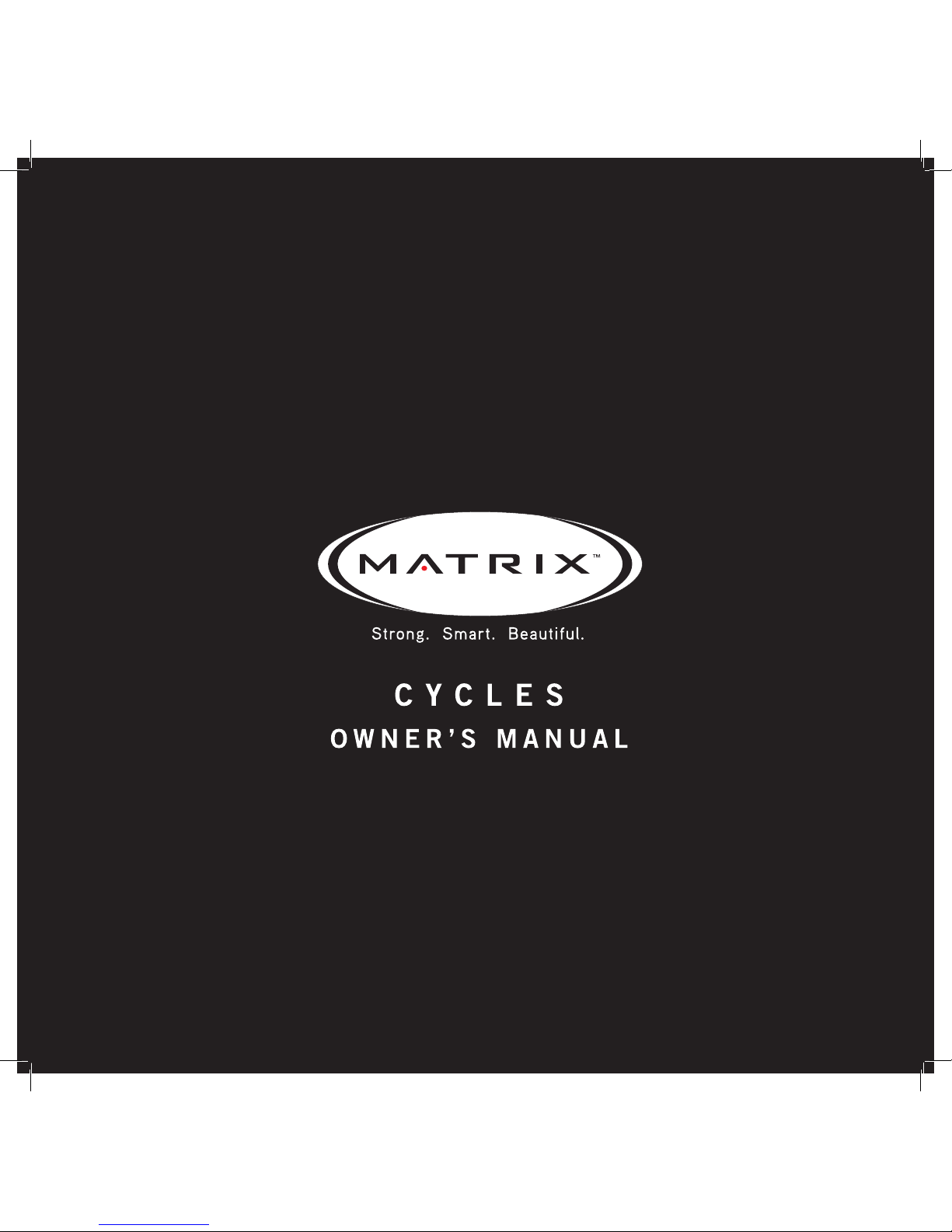
2.1 RECUMBENT SEAT HEIGHT
To adjust the seat height on the Recumbent Cycle, locate the yellow lever
under the right side of the seat before you mount the Cycle. Place your right
hand on the yellow adjustment handle under the right side of the seat. Place
feet on the ground while seated and slide forward if needed. Place feet on
pedals, gently lift lever under the right side of the seat. Using legs, slowly
push and slide the seat up or down to desired position. Release lever and
allow to lock into place.
2.2 UPRIGHT SEAT HEIGHT
To adjust the seat height on the Upright Cycle, locate the yellow pull pin
before you mount the Cycle. To raise or lower the seat, pull the yellow knob
while holding the seat with the other hand and slide up or down accordingly.
Make sure you are not seated when you pull the knob or pull the seat up.
2.3 HYBRID SEAT HEIGHT
To adjust the seat height on the Hybrid Cycle, pull the yellow lever under the
seat and lower the seat to the lowest position, stand over the seat and grab
the yellow lever. Pull the lever and lift until the seat base makes contact with
your pelvic bone.
Cycles_OM_090430.indd 2 4/30/09 10:40 AM
Page 7
3
CHAPTER 4: U
sing the recumbent, upright or hybrid cycle
™
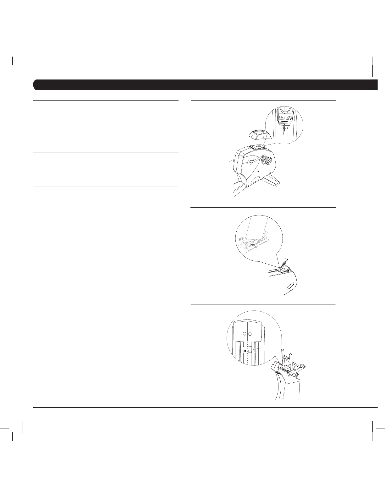
4.1 CONSOLE DESCRIPTION
PROGRAMS: Simple program selection buttons make Matrix Cycles easy to
use. Matrix Cycles feature eight programs.
START/QUICK START: One Touch Quick Start and Start any time during pref-
erence selection.
UP/DOWN: Easy information and level selection.
SELECT/SELECT SCREEN/ RESET: This multi-function button enters informa-
tion when setting up programming options, toggles information displayed and
if held down for 5 seconds, resets the Cycle to Start-up mode.
4.2 MANUAL OPERATION
QUICK START: start pedaling and press “START” to being your workout. All
energy expenditure values will be calculated using the default
weight measurement.
MANUAL MODE: Manual is a workout that allows you to manually adjust the
resistance at any time. The manual workout also contains a setup screen
which allows you to input your weight to help calculate a more accurate
caloric burn rate.
• Press “MANUAL”.
• Enter your desired “TIME” using the ARROW KEYS or NUMBER KEYPAD
and press ENTER.
• Enter your desired “LEVEL” using the ARROW KEYS or NUMBER
KEYPAD and press ENTER.
• Enter your “WEIGHT” using the ARROW KEYS or NUMBER KEYPAD and
press ENTER.
4.3 OPERATING LEVEL BASED PROGRAMS
Your Matrix Cycle offers versatile programs to keep the user motivated.
The following instructions will guide you through the simple steps to select
Intervals, Rolling, Fat Burn and Random workouts.
• Press the Workout Button of choice.
• Enter your desired “TIME” using the ARROW KEYS or NUMBER KEYPAD
and press ENTER.
• Enter your desired “LEVEL” using the ARROW KEYS or NUMBER
KEYPAD and press ENTER.
• Enter your “WEIGHT” using the ARROW KEYS or NUMBER KEYPAD and
press ENTER.
4.4 USER DEFINED PROGRAMS - RANDOM
RANDOM - there are 20 workout profiles in RANDOM mode. Profile will change
each time RANDOM key is pressed. Select a workout profile, follow user
informantion prompts or press QUICK START key to begin.
STEP 1: Select the PROGRAM button.
Press SELECT or wait 5 seconds.
Selecting START will start program.
STEP 2: Select TIME by using the UP or DOWN arrow keys.
Press SELECT or wait 5 seconds.
Selecting START will start program.
STEP 3: Select LEVEL by using the UP or DOWN arrow keys.
You can change the level at any time during workout.
Press SELECT or wait 5 seconds.
Selecting START will start program.
STEP 4: Select weight by using the UP or DOWN arrow keys.
Press START or SELECT to begin workout.
Display, Starting 3, Starting 2, Starting 1.
Cycles_OM_090430.indd 3 4/30/09 10:40 AM
Page 8

4
CHAPTER 4: U
sing the recumbent, upright or hybrid cycle
™
4.5 FIT TEST
This test measures cardiovascular fitness and proves an estimated
sub-maximal VO2 result. It is based on power output according to ACSM
standards and was developed by the Cooper Institute
(© www.cooperinstitute.org)
User RPMs must remain between 60-80 RPM during the test.
The test will end when the user can no longer maintain this speed. Use of a
heart rate strap is optional but provides more data.
The test starts at a low intensity level and gradually increases in intensity
(difficulty) every 2 minutes. As it increases, the user must maintain 6080RPM to advance to the next level. The test could take upwards of 30+
minutes for very fit individuals. Once the test ends a recovery period (cool
down) will begin and the user’s results are calculated and displayed. Results
are based on the following:
10-20% - Well Below Average
30-40% - Below Average
50% - Average
60-70% - Above Average
80-90% - Well Above Average
Percentile Values for Maximal Aerobic Power
Age
Percentile 20-29 30-39 40-49 50-59 60+
Men
90 51.4 50.4 48.2 45.3 42.5
80 48.2 46.8 44..1 41.0 38.1
70 46.8 44.6 41.8 38.5 35.3
60 44.2 42.4 39.9 36.7 33.6
50 42.5 41.0 38.1 35..2 31.8
40 41.0 38.9 36.7 33.8 39.2
30 39.5 37.4 35.1 32.3 28.7
20 37.1 35.4 33.0 30.2 26.5
10 34.5 32.5 30.9 28.0 23.1
Women
90 44.2 41.0 39.5 35.2 35.2
80 41.0 38.6 36.3 32.3 31.2
70 38.1 36.7 33.8 30.9 29.4
60 36.7 34.6 32.3 29.4 27.2
50 35.2 33.8 30.9 28.2 25.8
40 33.8 32.3 29.5 26.9 24.5
30 32.3 30.5 28.3 25.5 23.8
20 30.6 28.7 26.5 24.3 22.8
10 28.4 26.5 25.1 22.3 20.8
Cycles_OM_090430.indd 4 4/30/09 10:40 AM
Page 9
5
™
CHAPTER 4: U
sing the recumbent, upright or hybrid cycle
™
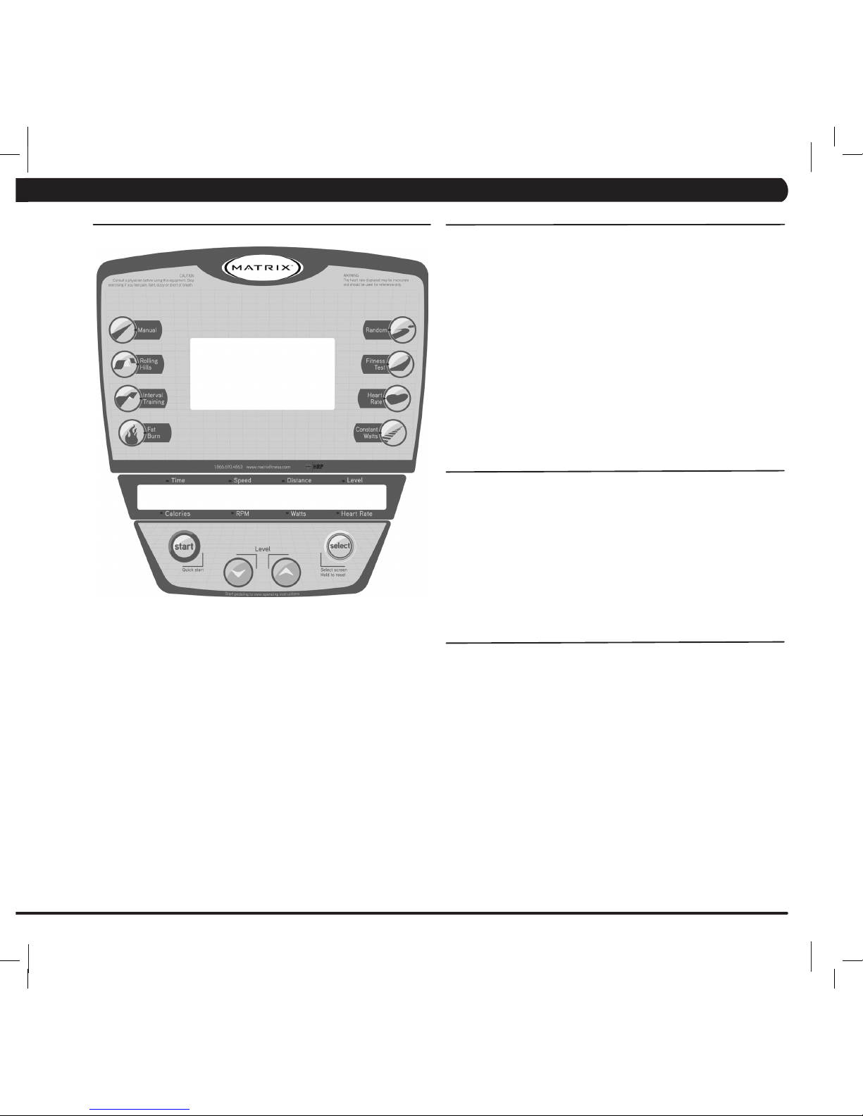
4.6 HEART RATE CONTROL
Your Matrix Cycle offers a heart rate control workout mode. The heart rate
control workout mode allows the user to program their desired heart rate
zone and the cycle will adjust the resistance automatically based on the
user’s heart rate. The heart rate zone is calculated using the following equation: (220-Age)*% = target heart rate zone. The user must wear a telemetric
heart rate monitor or continually hold onto the contact heart rate grips for
this workout.
• Press “TARGET HEART RATE”.
• Enter your “AGE” using the ARROW KEYS or NUMBER KEYPAD and
press ENTER.
• Enter your desired percentage of maximum heart rate using the ARROW
KEYS or NUMBER KEYPAD and press ENTER.
• Enter your desired “TIME” using the ARROW KEYS or NUMBER KEYPAD
and press ENTER.
• Enter your “WEIGHT” using the ARROW KEYS or NUMBER KEYPAD and
press ENTER (user weight is used to calculate the caloric expenditure
during the workout).
4.7 CONSTANT WATTS
CONSTANT WATTS workout is a unique program that allows you to vary
your cadence or RPM and the Cycle’s resistance will adjust accordingly to
your selected goal. The quicker you pedal the less resistance for the goal
selected.
• Press “CONSTANT WATTS”
• Enter your desired “WATT” using the ARROW KEYS or NUMBER KEYPAD
and press ENTER (25 – 525).
• Enter your desired “TIME” using the ARROW KEYS or NUMBER KEYPAD
and press ENTER.
• Enter your “WEIGHT” using the ARROW KEYS or NUMBER KEYPAD and
press ENTER.
Cycles_OM_090430.indd 5 4/30/09 10:40 AM
Page 10

6
SPECIFICATIONS
Product Name R3x-01
Foot Print inches = 64”
L x 29”W x 51”H
cm = 162.5 x 73.5 x 129.5
Weight 170 lbs
77 kg
Max User Weight 400 lbs = 181 kg
Frame Construction Steel
Self Contained Yes
Resistance Type Generator
Resistance Level 25
PROGRAMS
One Button Quick Start Yes
Random (20 profiles) Yes
Target Heart Rate Yes
Interval Yes
Constant Watts Yes
Rolling Yes
Fat Burn Yes
Fit Test Yes
HEART RATE
Wireless Heart Rate Yes
Contact Heat Rate Yes
ENTERTAINMENT READY
Coaxial Cable Connection Yes
AC TV Power Connection Yes
Monitor Mount Yes
CHAPTER 5: R
ecumbent Cycle Specifications
, P
arts And Assembly Steps
5.1 R3x RECUMBENT CYCLE SPECIFICATIONS
Cycles_OM_090430.indd 6 4/30/09 10:40 AM
Page 11

7
04 Z12 SPRING WASHER WHITE
02 Z13 BUTTON HEAD BOLT M5 x 10L WHITE
08 Z21 BUTTON HEAD BOLT M5 x 20L BLACK
08 Z22 FLAT WASHER BLACK
08 Z23 SPRING WASHER BLACK
04 Z31 BUTTON HEAD BOLT M8 x 15L YELLOW
01 4mm ALLEN WRENCH
01 5mm ALLEN WRENCH
01 6mm ALLEN WRENCH
01 OPEN WRENCH [ #15 # 17 325L ]
01 #2 PHILLIPS SCREW DRIVER [ 6 x 130]
QTY PART # SKETCH DESCRIPTION NOTES
04 Z32 FLAT WASHER YELLOW
04 Z33 SPRING WASHER YELLOW
02 Z34 BUTTON HEAD BOLT M8 x 25L YELLOW
03 Z41 BUTTON HEAD BOLT M8 x 15L RED
04 Z42 BUTTON HEAD BOLT M8 x 50L RED
04 Z43 ARC WASHER RED
04 Z44 SPRING WASHER RED
03 Z45 HEXAGON FLAT HEAD BOLT M8 x 15L RED
04 D55 SOCKET HEAD BOLT Included in handle assembly
02 D57 SPRING WASHER Included in handle assembly
04 N51 BUTTON HEAD MACHINE SCREW M5 x 12 Included in console
04 Z11 BUTTON HEAD MACHINE SCREW M8 x 25L WHITE
01 CENTER LEVELER
01 9V BATTERY
Included in packaging
01 SEAT ADJUSTMENT HANDLE
Included in packaging
CHAPTER 5: R
ecumbent Cycle Specifications
, P
arts And Assembly Steps
5.2 R3x RECUMBENT CYCLE REQUIRED FASTENERS & ASSEMBLY TOOLS INCLUDED
R3x • RECUMBENT CYCLE
Cycles_OM_090430.indd 7 4/30/09 10:40 AM
Page 12

8
STEP 1
Z21
Z22
Z23
Z21
Z22
Z23
REMOVE SHIPPING SPACER
STEP 2
Lightly grease
Z32
Z11
Z31
Z33
D55
D57
CENTER LEVELER
SEAT ADJUSTMENT HANDLE
CHAPTER 5: R
ecumbent Cycle Specifications
, P
arts And Assembly Steps
5.3 R3x RECUMBENT CYCLE ASSEMBLY STEPS
R3x • RECUMBENT CYCLE
Cycles_OM_090430.indd 8 4/30/09 10:40 AM
Page 13

9
STEP 4
STEP 3
Z45
Z42
Z11
Z13
Z12
Z44
Z43
Z41
Z44
CHAPTER 5: R
ecumbent Cycle Specifications
, P
arts And Assembly Steps
5.3 R3x RECUMBENT CYCLE ASSEMBLY STEPS
Cycles_OM_090430.indd 9 4/30/09 10:40 AM
Page 14

10
STEP 5
FINAL ASSEMBLY
INCLUDED
WITH CONSOLE
N51
BATTERY
9V
Z34
Water Bottle
Holder (C08)
CHAPTER 5: R
ecumbent Cycle Specifications
, P
arts And Assembly Steps
5.3 R3x RECUMBENT CYCLE ASSEMBLY STEPS
Cycles_OM_090430.indd 10 4/30/09 10:40 AM
Page 15

11
CHAPTER 5: R
ecumbent Cycle Specifications
, P
arts And Assembly Steps
5.3 R3x OPTIONAL ENTERTAINMENT ACCESSORY SHOWN
Cycles_OM_090430.indd 11 4/30/09 10:40 AM
Page 16

12
SPECIFICATIONS
Product Name U3x-01
Foot Print inches = 47”
L x 29”W x 56”H
cm = 119.4 x 73.5 x 142.2
Weight 129 lbs
59 kg
Max User Weight 400 lbs = 181 kg
Frame Construction Steel
Self Contained Yes
Resistance Type Generator
Resistance Level 25
PROGRAMS
One Button Quick Start Yes
Random (20 profiles) Yes
Target Heart Rate Yes
Interval Yes
Constant Watts Yes
Rolling Yes
Fat Burn Yes
Fit Test Yes
HEART RATE
Wireless Heart Rate Yes
Contact Heat Rate Yes
ENTERTAINMENT READY
Coaxial Cable Connection Yes
AC TV Power Connection Yes
Monitor Mount Yes
CHAPTER 6: U
pright Cycle Specifications
, P
arts And Assembly Steps
6.1 U3x UPRIGHT CYCLE ASSEMBLY STEPS
Cycles_OM_090430.indd 12 4/30/09 10:40 AM
Page 17

13
04 Z11 SOCKET HEAD CAP SCREW M8 x 25L WHITE
04 Z12 SPRING WASHER WHITE
01 4mm ALLEN WRENCH
01 5mm ALLEN WRENCH
01 6mm ALLEN WRENCH
01 OPEN WRENCH [ #15 # 17 325L ]
01 #2 PHILLIPS SCREW DRIVER [ 6 x 130]
02 Z13 BUTTON HEAD MACHINE SCREW M5 x 10L WHITE
08 Z21 SOCKET HEAD CAP SCREW M8 x 20L BLACK
08 Z22 FLAT WASHER BLACK
08 Z23 SPRING WASHER BLACK
04 Z32 SPRING WASHER YELLOW
04 Z33 FLAT WASHER YELLOW
04 Z31 BUTTON HEAD SCREW M8 x 20L YELLOW
02 Z34 SOCKET HEAD CAP SCREW M8X25L YELLOW
04 Z41 BUTTON HEAD CAP SCREW CHROME PLATED M8X20L RED
04 Z42 FLAT WASHER - CHROME PLATED RED
04 Z43 SPRING WASHER - CHROME PLATED RED
04 Z51 HEX SOCKET HEAD CAP SCREW M5 x 12L GREEN
04 Z52 SPRING WASHER - CHROME PLATED GREEN
04 N51 BUTTON HEAD MACHINE SCREW Included with console
QTY PART # SKETCH DESCRIPTION PACKAGE COLOR
01 9V BATTERY
01 C12 CONSOLE FIX PLATE
Included in packaging
CHAPTER 6: U
pright Cycle Specifications
, P
arts And Assembly Steps
6.2 U3x UPRIGHT CYCLE REQUIRED FASTENERS & ASSEMBLY TOOLS INCLUDED
U3x • UPRIGHT CYCLE
Cycles_OM_090430.indd 13 4/30/09 10:40 AM
Page 18

14
STEP 1
STEP 2
Lightly grease
Z21
Z22
Z23
Z21
Z22
Z23
Z31
Z32
Z33
Z42
Z43
Z41
REMOVE SHIPPING SPACER
CHAPTER 6: U
pright Cycle Specifications
, P
arts And Assembly Steps
U3x • UPRIGHT CYCLE
6.3 U3x UPRIGHT CYCLE ASSEMBLY STEPS
Cycles_OM_090430.indd 14 4/30/09 10:40 AM
Page 19

15
STEP 3
STEP 4
Z12
Z11
Z13
N51
Z52
Z51
INCLUDED WITH
CONSOLE
CONSOLE
FIX PLATE
BATTERY
9V
CHAPTER 6: U
pright Cycle Specifications
, P
arts And Assembly Steps
6.3 U3x UPRIGHT CYCLE ASSEMBLY STEPS
Cycles_OM_090430.indd 15 4/30/09 10:40 AM
Page 20

16
STEP 5
FINAL ASSEMBLY
Z34
Water Bottle
Holder (C08)
CHAPTER 6: U
pright Cycle Specifications
, P
arts And Assembly Steps
6.3 U3x UPRIGHT CYCLE ASSEMBLY STEPS
Cycles_OM_090430.indd 16 4/30/09 10:40 AM
Page 21

17
CHAPTER 6: U
pright Cycle Specifications
, P
arts And Assembly Steps
6.3 U3x OPTIONAL ENTERTAINMENT ACCESSORY SHOWN
Cycles_OM_090430.indd 17 4/30/09 10:40 AM
Page 22

18
CHAPTER 7: H
ybrid Cycle Specifications
, P
arts And Assembly Steps
7.1 H3x HYBRID CYCLE ASSEMBLY STEPS
H3x-01
Cycles_OM_090430.indd 18 4/30/09 10:40 AM
Page 23

19
04 Z11 SOCKET HEAD BOLT M8 x 25L WHITE
04 Z12 SPRING WASHER WHITE
02 Z13 BUTTON HEAD BOLT M5 x 10L WHITE
08 Z21 SOCKET HEAD BOLT M8 x 15L BLACK
08 Z22 FLAT WASHER BLACK
08 Z23 SPRING WASHER BLACK
04 Z31 SOCKET HEAD BOLT M8 x 20L YELLOW
04 Z32 FLAT WASHER YELLOW
04 Z33 SPRING WASHER YELLOW
02 Z34 SOCKET HEAD BOLT M8 x 25L YELLOW
08 Z41 BUTTON HEAD BOLT M8x50L RED
08 Z42 ARC WASHER RED
08 Z43 SPRING WASHER RED
04 Z51 SOCKET HEAD BOLT M8 x 15L GREEN
04 Z52 FLAT WASHER GREEN
04 Z53 SPRING WASHER GREEN
04 N51 CROSS TRUSS HEAD Included in console
01 4mm ALLEN WRENCH
01 5mm ALLEN WRENCH
01 6mm ALLEN WRENCH
01 OPEN WRENCH [ #15 # 17 325L ]
01 #2 PHILLIPS SCREW DRIVER [ 6 x 130]
QTY PART # SKETCH DESCRIPTION PACKAGE COLOR
01 9V BATTERY
Included in packaging
01 CENTER LEVELER
CHAPTER 7: H
ybrid Cycle Specifications
, P
arts And Assembly Steps
7.2 H3x HYBRID CYCLE REQUIRED TOOLS & ASSEMBLY TOOLS INCLUDED
H3x • HYBRID CYCLE
Cycles_OM_090430.indd 19 4/30/09 10:40 AM
Page 24

20
STEP 1
Lightly grease
STEP 2
Z31
Z33
Z32
Z22
Z23
Z21
Z22
Z23
Z21
Z52
Z51
Z53
Z41
Z42
Z41
Z42
CENTER LEVELER
CHAPTER 7: H
ybrid Cycle Specifications
, P
arts And Assembly Steps
H3x • HYBRID CYCLE
7.3 H3x HYBRID CYCLE ASSEMBLY STEPS
Cycles_OM_090430.indd 20 4/30/09 10:40 AM
Page 25

21
STEP 3
STEP 4
Z13
Z12
Z11
INCLUDED
WITH
CONSOLE
N51
BATTERY
9V
CHAPTER 7: H
ybrid Cycle Specifications
, P
arts And Assembly Steps
7.3 H3x HYBRID CYCLE ASSEMBLY STEPS
Cycles_OM_090430.indd 21 4/30/09 10:41 AM
Page 26

22
STEP 5
FINAL ASSEMBLY
Z34
Water Bottle
Holder (C08)
CHAPTER 7: H
ybrid Cycle Specifications
, P
arts And Assembly Steps
7.3 H3x HYBRID CYCLE ASSEMBLY STEPS
Cycles_OM_090430.indd 22 4/30/09 10:41 AM
Page 27

23
™
CHAPTER 7: H
ybrid Cycle Specifications
, P
arts And Assembly Steps
7.3 H3x OPTIONAL ENTERTAINMENT ACCESSORY SHOWN
Cycles_OM_090430.indd 23 4/30/09 10:41 AM
Page 28

Cycles_OM_090430.indd 24 4/30/09 10:41 AM
Page 29

MAT R I X F I T N E S S S Y S T E M S C O R P.
1610 LANDMARK DR I V E C O T TAGE GROVE W I 5 3 5 2 7 U S A
TOLL FREE 8 6 6.693.48 6 3
w w w. m at ri xf i tn ess . co m
FAX 6 0 8 . 8 3 9 . 8 6 8 7
PA R T # 0 0 0 0 0 9 2 5 5 4
REV. 1.3
Cycles_OM_090430.indd 25 4/30/09 10:41 AM
 Loading...