

Page 1
1
Issue date
2017-03-14
Edition 01 Doc No.
SM-TM-AF-
017
Revision
date
01 Page 22
Johnson
Approval Review Editor
Kyle Schweitzer Dora Feng
U-1X-F & R-1X-F
Service Manual
Johnson Industries (Shanghai) Co.,Ltd
Page 2
2
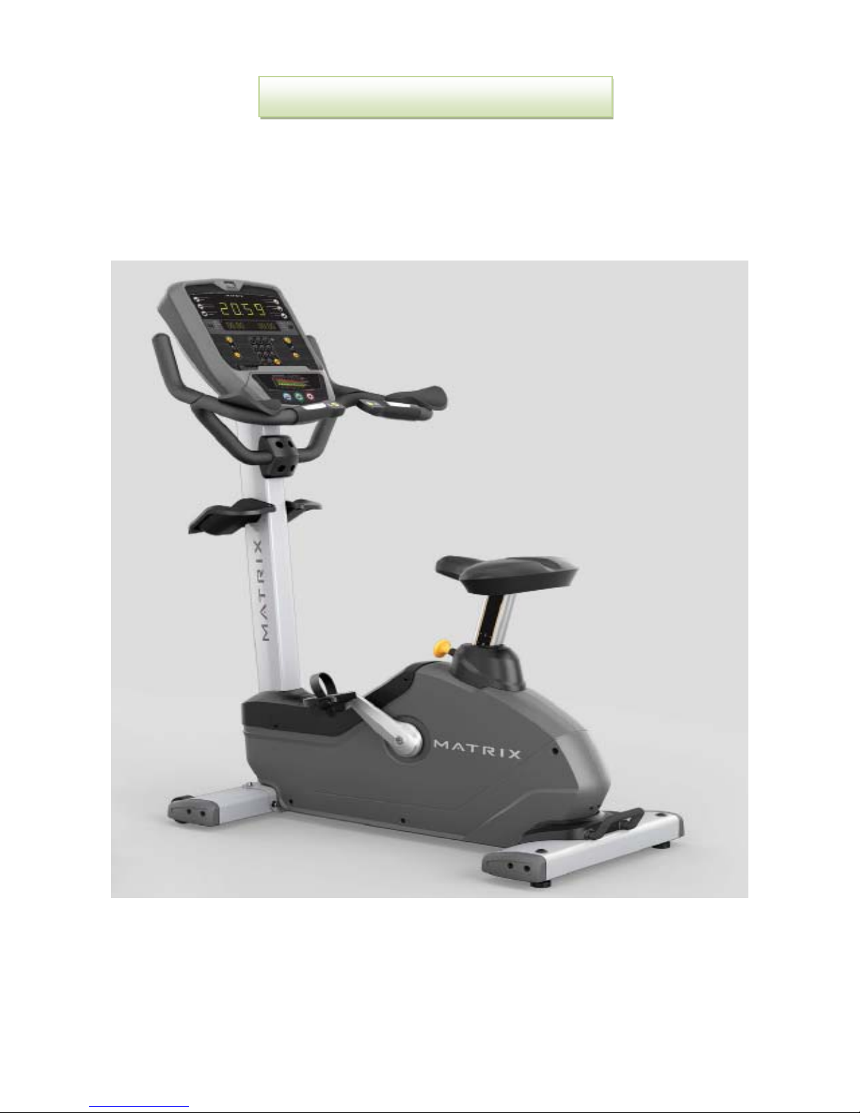
Production Browse
U-1X-F
Page 3
3
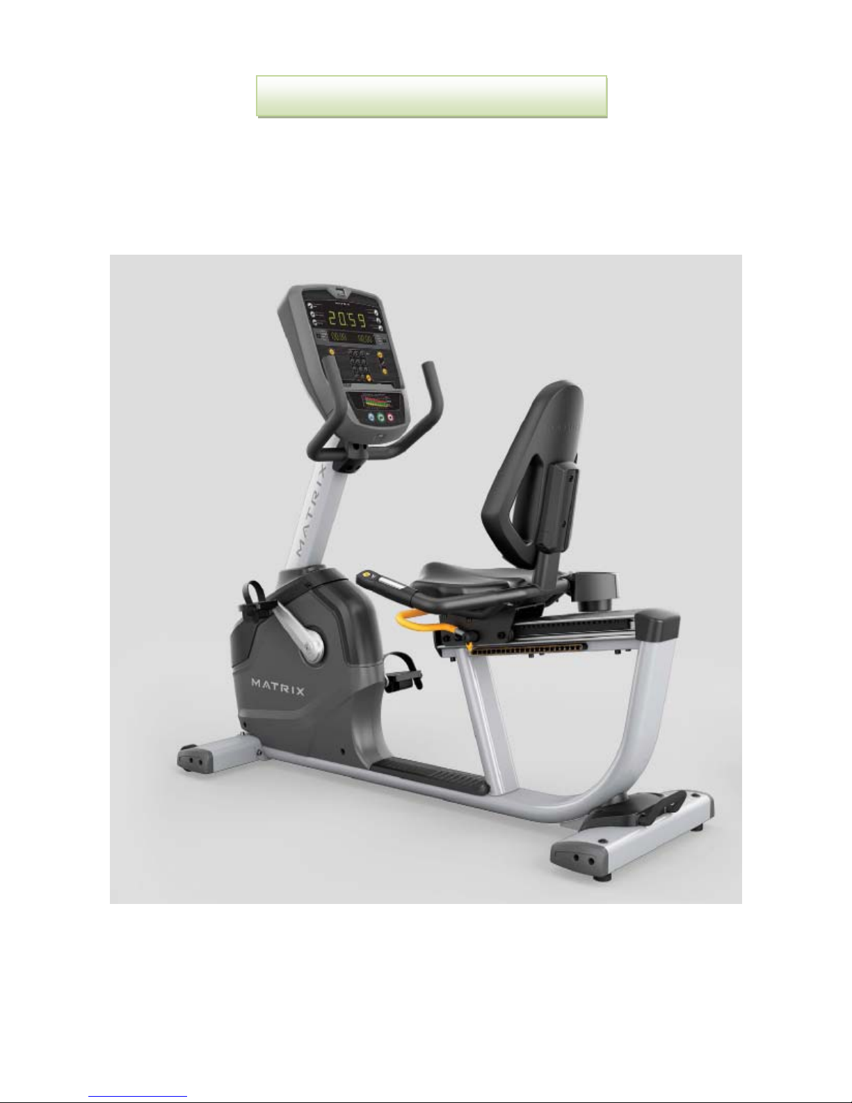
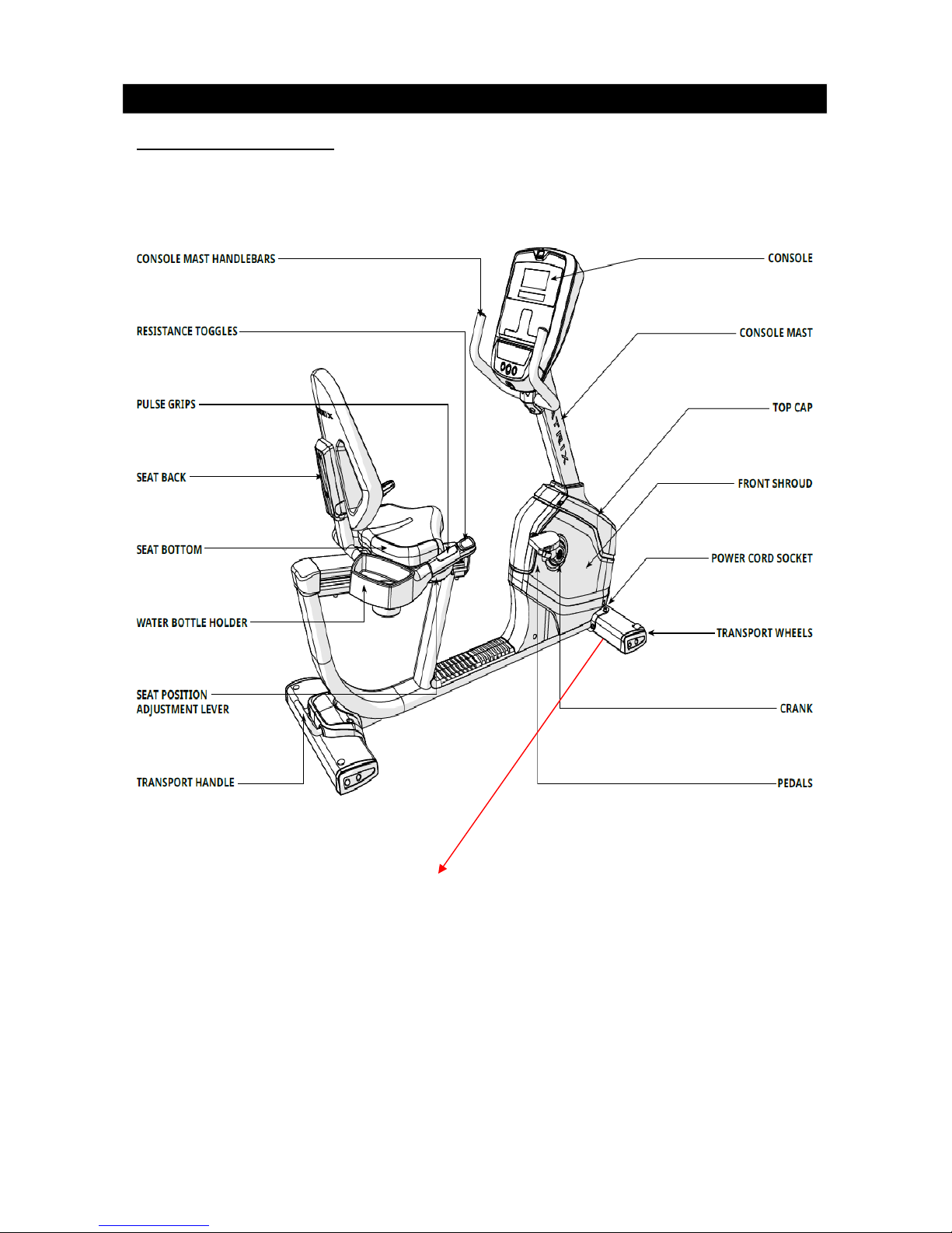
Production Browse
R-1X-F
Page 4

4
Contents
Chapter 1: Serial Number Location…………………………………………………………..5
Chapter 2: Troubleshooting
2.1 Electrical Diagram……………………………………………………………………….6
2.2 MCB Instruction………………………………………………………………………… 9
2.3 No Power to the Console……………………………………………………………...10
2.4 Heart Rate Issue/Quick Keypad ……………………………………………………..11
2.5 No Resistance or Incorrect Resistance……………………………………………...12
Chapter 3: Part Replacement
3.1 Console Replacement…………………………………………………………………13
3.2 Handlebar Replacement………………………………………………………………13
3.3 Console Mast Replacement…………………………………………………………..14
3.4 Pedal Set Replacement……………………………………………………………….15
3.5 Crank Replacement………………………… ………………………………………..15
3.6 Side Cover Replacement……………………………………………………………...16
3.7 Generator Replacement……………………………………………………………….17
3.8 MCB Replacement……………………………………………………………………..18
3.9 Seat Carriage Replacement…………………………………………………………..19
3.10 Drive B
elt Replacement……………………………………………………………....20
3.11. Drive Axle replacement………………………………………………………………21
Page 5
5
CHAPTER 1: Serial Number Location
Serial Number Location
Serial Number Location
U-1X-F
Notes: please refer to cons
ole service manual to get more information
Page 6
6
CHAPTER 1: Serial Number Location
Serial Number Location
R-1X-F
Serial Number Location
Notes: please refer to cons
ole service manual to get more information
Page 7
7
CHAPTER 2: Troubleshooting
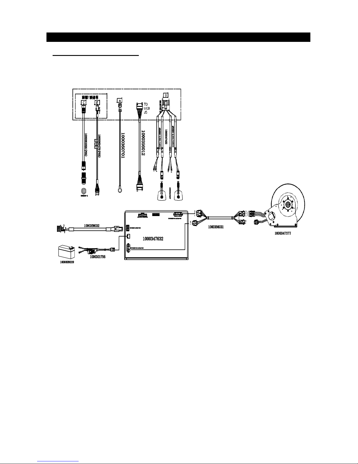
2.1 ELECTRICAL DIAGRAM
2.1.1 U-1X-F Electrical Diagram
Page 8

8
CHAPTER 2: Troubleshooting
2.1 ELECTRICAL DIAGRAM
2.1.2 R-1X-F Electrical Diagram
Page 9

9
CHAPTER 2: Troubleshooting
2.2 MCB Instruction
When the LED10 Error light turns on, it means to check the related
error code on the c
onsole. See console service manual.
Page 10

10
CHAPTER 2: Troubleshooting
2.3 No power to the console
Symptom:
No power to the console.
2) Solution:
a. The adapter for this model is 12V - 5A. Check to make sure the power adapter on the unit is cor-
rec
t. Test the power adapter in a known good outlet. Replace the adapter if it is defective.
b. Check the connection of the console cable at the console (Fig1). Unplug the console cable from
console, and use a multi-meter to check the voltage through the console cable. Pin 1 or 2 and pin 7
or 8. it should be 12VDC. If no voltage is present, the console cable is defective, replace it.
c. If the voltage through the console cable is 12VDC, the console is defective, replace it.
Fig1
Page 11

11
CHAPTER 2: Troubleshooting
2.4 Heart Rate/Quick Keypad Issue
Symptom: Heart Rate Function Does Not Work or is Reading Incorrectly
Quick Key Function Does Not Work or Works Incorrectly
Solution:
A. Heart Rate:
1.The heart rate grips are not connected properly or are defective.
With a multi-meter set for DC voltage, plac
e one terminal on each of the HR grip plates.
(Fig1) The
HR g
rip should give a voltage reading of between 0.5 and 2.0VDC
. If the voltage is not between 0.5
and 2.0VDC, remove the 3
screws holding the HR grip together and check the conne
ction of the HR
grip wiring.
2.The heart rate grip wiring is
damaged or not connected correctly.
Check continuity of the HR grip wiring.
Place one terminal of a multi-meter set for resistance on the HR grip wiring at the HR grip, and the
other terminal on the HR grip wiring at the console. An ohm reading of around 1 should be expected.
If the reading is higher than 1, replace the HR grip wiring.
3. The HR board is damaged
Remove the
console. Remove the 6 screws holding the front of the console to the rear. Check the
connection of the HR board wiring to the UCB. If all the wiring is intact and has good contact, replace
the HR board.
4.The UCB is damaged.
If the HR board, HR
grips, and HR grip wiring do not solve the issue, replace the UCB.
B. QUICK Key ISSUE
The keypad connection wires are not connected properly or are defective.
With a multi-meter set for ohms, place one terminal on quick key
slot red wire (Fig2) .the others terminal place one connection slot (fig3). It should read 0 ohms. If not . It mean wire damage. Replace
new console wire.
Fig1
Fig2
Fig3
Page 12

12
CHAPTER 2: Troubleshooting
2.5 No Resistance Or Incorrect Resistance
U-1X-F/R-1X-F
1. Check the Connection wire between the console and MCB. Unplug the connector (Page 10 Fig1), and
then plug it in again.
2. Check
theconnection wire between MCB and Induction Brake/generator. Unplug the connection wire
between the quick key pad and console. Be sure not to mix up the right and left quick key
connection wire ends. See U-1X-F (Fig1) and R-1X-F (Fig1 & Fig-2)
Fig-1
Fig-2
Page 13

13
CHAPTER 3 Part Replacement
3.1 Console Replacement
1. Remove 5 bolts on the console back;
2.
Disconnect the wires;
3.
Reverse steps to install a new.
3.2 Handlebar Replacement
1. Remove 4 bolts (I) first;
2.
Remove 2 screws (H);
3.
Reverse steps to install a new.
Notes: the same method for U-1X-F & R-1X-F handlebar replacement.
Page 14

14
CHAPTER 5 Part Replacement
3.3 Console Mast Replacement
For U-1X-F
1.
Remove 4 screws on rear cover, like st
ep 1.
2.
Remove 2 screws on the front cover, like step 2.
3.
Remove 4 bolts which fixed the console mast, like step 3.
4.
Reverse steps to install new console mast.
For R-1X-F
1.
Remove 2 screws on front cover, like st
ep 1.
2.
Remove 2 screws on the rear cover, like step 2.
3.
Remove 4 bolts which fixed the console mast, like step 3.
4.
Reverse steps to install new console mast.
U-1X-F
R-1x-F
CHAPTER 3 Part Replacement
Page 15

15
CHAPTER 5 Part Replacement
3.4 Pedal Set Replacement
(1) Using a 15mm pedal wrench, firmly hold opposite crank arm for leverage. (Figure A)
Notes: left pedal is left hand threads.
(2) Reverse step one to install pedals.
FIGURE A
3.5 Crank Replacement
(1) The crank
arm is fixed with a self extracting crank bolt. You must lubricant under extractor cap before
removing the crank bolt. If this is not done, damage can happen to the crank arm or extractor. With
an 8mm hex key, turn the crank bolt counter-clockwise to remove crank arm. The torque is 800lbs.
(Figure B)
(2) Reverse step one to replace the crank arm.
CHAPTER 3 Part Replacement
FIGURE B
Page 16

16
CHAPTER 5 Part Replacement
3.6 Side Cover Replacement
1. Remove the pedal set (section 3.4)
2. Remove c
rank set (section 3.5)
3. Remove 10 screws on both right and left covers, Figure A.( U-1X-F)
4. Remove 11 screws on both right and left covers, Figure B .(R-1X-F)
5. Reverse steps to install new one.
Figure A
Figure B
CHAPTER 3 Part Replacement
Page 17

17
CHAPTER 5 Part Replacement
3.7 Generator Replacement- (U-1X-F) & (R-1X-F)
1) Remove side cover (section 3.6)
2) Remove fixing bolts and remove generato
r
3) Install new generator
4) Reve
rse steps to replace generator.
NOTE: hexagon spanner may be needed, the torque is 10N.M.
U-1X-F
R-1X-F
Page 18

18
CHAPTER 5 Part Replacement
3.8 MCB Replacement
1) Remove side cover (section 3.6)
2) Disconnect wire
s.
3) Re
move screws which fixed MCB.
4) Reve
rse steps to replace a new.
U-1X-F
R-1X-F
Note: the circuit board could become damaged during this procedure from electro-
static discharge. We recommend wearing an ESD wrist strap.
Page 19

19
CHAPTER 3 Part Replacement
3.9 Seat Carriage Replacement-R-1X-F
1) Remove side cover (section 3.6)
2) Remove the screws.
3) Di
sconnect the heart rate wire with power wire.
4) Reve
rse steps to replace.
Page 20

20
CHAPTER 3 Part Replacement
3.10 Drive Belt Replacement
1. Remove side cover (see section 3.6)
2.Remove drive belt
3.Install new driv
e belt
4.Reverse steps to replace
5.Measure belt tension that it should be 200HZ -220HZ
U-1X-F
R-1X-F
Page 21

21
CHAPTER 3 Part Replacement
3.11 Drive axle Replacement
(FIGURE-A)
(FIGURE-B)
5. Add C buckle (FIGURE-B)
6.
Press bearing by fixture (FIGURE
-C)
7.
Roll the wheel to see if smooth (FIGURE-D)
(FIGURE-C)
(FIGURE-D)
1.Remove side cover (see section 3.6)
2.Remove drive belt
3.Ins
tall new drive axle
4.Reverse steps to replace.
 Loading...