

Page 1
Product instruction manual
Matrix Single Side Laminators
The Matrix has been designed to be user friendly,
however we strongly recommend you take a few minutes
to read through this manual to ensure correct operation.
Keep this manual safe for future reference.
Page 2
2 3
Page 3 - Introduction
Page 4 - Safety Instructions and environmental requirements
Page 5 - Control panel and display screen
Pages 6 & 7 - Operation & installation of laminating lms
Page 8 - Warranty and incorrect use
Thank you for purchasing the Matrix single sided laminator.
Matrix is a high performance single sided laminating system with a solid construction
built to last.
Please read these instructions carefully before starting to use the system to ensure you
get the best results and are competent at operation.
Should you experience any problems please contact us and we will be happy to help.
Matrix 370
Matrix 530
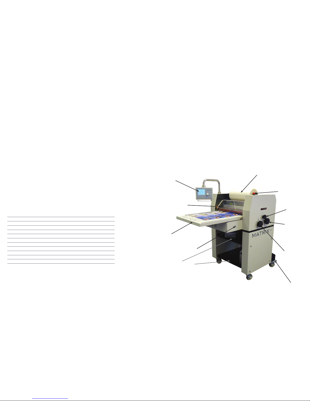
Contents Introduction
DIGITAL DISPLAY
SAFETY GUARD
FEED TRAY
FOOT SWITCH PLUG-IN
FILM STORAGE TRAYS
BRAKE LOCK
LAMINATING
ROLLER LIFT
REAR PULL
ROLLER LIFT
ANTI-CURL
SETTING
EMERGENCY STOP
FILM MANDREL
MX-370 MX-530
Max Laminating Width 340mm 500mm
Max Laminating Thickness 135gsm
Temperature Range 0-140°C
Approx. Highest Line Speed 10m/min
Maximum Sheet Width 420 550
Warm up Time 10 mins
Power consumption 2200 2400
Power Supply Required 13 Amps
Power Supply 220/240 V
Rate Input Power 900W 1000W
Dimensions 800 x 1800 x 1400mm 900 x 2050 x 1400mm
Gross Weight 190kg 220kg
Specications
Page 3

4 5
• Ambient temperature 10°C - 60°C, humidity 30% - 80%, Ideal humidity 55%
• Dust - Due to the static adherence of the lm, you should keep the environment clean, a
dust cover is provided with the machine
• Please do not keep the machines in direct sunlight
• Please do not keep the machine in or around dusty areas
• Enough space should be kept around the machine to ensure the secure and eective ap-
plication. The minimum holding areas are 2.5m x 3m
Environmental Requirements
Safety Instructions
The Control Panel
• Please ensure that the voltages of power supply you are using match with rated working
voltages before operating the machine
• The power supply should be close to the machine for convenient use
• The power supply should provide reliable protective earthing connection
• This machine must be earthed reliably so as to ensure the safety of the machine during
operation
• Only the operators of this machine should operate the electric or motion components/
controls
• Please don’t use damaged wires or sockets
• Please keep children away from touching and operating this machine
• Please do not spray water or other liquid on the machine otherwise electric shock or
machine faults could occur
• Please do not replace power cord or plugs yourself, do not put heavy objects on the
power lines as this may cause electric shocks
• During use please take care that no clothes, neckties, hair, necklaces etc are near the
machine otherwise injuries could occur
• Please don’t put burrs, sharp blades or over thick rigid materials into the two rubber cov-
ered rollers (for example, tools, rulers and knives etc.)
• Don’t cut adhesive lms directly on the surfaces of the rubber covered rollers to avoid
damage
• Please shut down this machine after laminating to avoid misuse of the machine
• At the end of the working day always gape the rollers to ensure no at spots or distor-
tions occur
• When you need to move this machine, please shut down the power switch and pull out
the plugs
• Please be aware of the location of the wheels during moving or operating this machine
to avoid foot injuries
• Always ensure the machine is positioned on a at and level oor
• Please shut o the power supply (pull out the power plug) when the machine isn’t going
to be used for long periods of time.
Display screen Function key Memory keys
Temperature
Setting
Screen
brightness
adjustment
Speed
setting
dial
Stop key
Reverse
rotation key
Crawl Key*Forward driveAnti-curl settingFine tune key for
cutting position
Paper
length
setting
*Functions with foot pedal only
Running
speed
The Display Screen
Sheet
length
Sheet
splitting
adjustment
Anti-curl setting (0-6) Actual temperature Screen brightness
Memory Set temperature
Sheet counter
Page 4

6 7
4. Set temperature, sheet length
and anti-curl setting.
5. Remove lm mandrel. 6. Using the allen key provided, loosen
screws on the core adaptor.
Set the required temperature using the
+ - temperature buttons
MATRIX set-up & Installation of Laminating Films
7. Remove one core adaptor. 8. Slide lm onto the mandrel and
centralize, replace core adaptor.
9. Place lm and mandrel back onto the
machine.
10. Ensure lm feeds from the bottom of
the roll.
11. Set the anti-curl device to the zero
position and ensure both laminating and
pull rollers are in the raised position.
12. Press rubber roller to drop gate and
slide in plain print, ensure it goes through
anti-curl device and into pull rollers.
1. Position the machine near a suitable 13
amp socket and plug into the mains.
2. Turn the power on. 3. Screen displayed, see large screen
diagram for functions on page 5.
13. Slide the second blank print around
the steel laminating roller, through the
anti-curl device and into the pull rollers.
14. Run the lm under the idler bar and
drape over the steel laminating roller.
15. Press second set-up print onto the
lm.
16. Replace the guard. 17. Ensure the micro switch is located,
otherwise the machine will not run.
18. Lower the laminating and pull rollers
and set the anti-curl to the desired
setting.
19. Set the perforation wheel, lock in
place on the edge of the lm which
should be in the paper margin (and not
on the print).
20. Turn the screw as the paper is feeding
until the perforation wheel starts to turn,
then lock into position.
21. Set the guide wheel to the opposite
side of the sheet from the perforation
wheel.
22. Finally, set the incline wheel on the
edge of the print on the same side as
the perforation wheel. Only a very small
angle is required.
1. Top paper feed roller. 2. Guide paper (end).
3. Front guard. 4. Steel laminating roller.
5. Idler bar. 6. Lamination roller lm. 7. Top pull roller.
8. Perforation wheel. 9. Top splitting roller.
10. Guide wheel. 11. Bottom roller for guide wheel.
12. Bottom splitting roller.
13. Perforation wheel support roller.
14. Bottom pull roller. 15. Anti-curl device.
16. Front bottom rubber laminating roller.
17. Paper stop. 18. Bottom paper feed roller.
19. Front operating panel. 20. Paper backing plate.
Place where the
paper core is stuck
to the lm
1st paper core
2nd paper core
Guide paper core (front end)
Page 5

Warranty & Incorrect Use
IMPORTANT INFORMATION
Your laminator should reach you in perfect condition, however please retain all original packaging once you have unpacked
your laminator in case you need to return it to us. If your laminator arrives damaged or faulty in anyway, this must be reported
to your supplier immediately. If you send your laminator back for repair under warranty at any time, then the warranty may be
void if the laminator is not packaged correctly and as a result is damaged in transit. The laminator you have purchased comes
with a 1 year warranty on defective parts. THIS DOES NOT COVER any jams, misfeeds or wrap arounds caused by operator error
and you will be liable for the repair costs (including delivery charges) if the damage is caused by operator error.
E&O.E
 Loading...